MOTOROLA SN74LS280D, SN74LS280DR2, SN74LS280M, SN74LS280MEL, SN74LS280ML1 Datasheet
...
SN74LS280
9-Bit Odd/Even Parity
Generators/Checkers
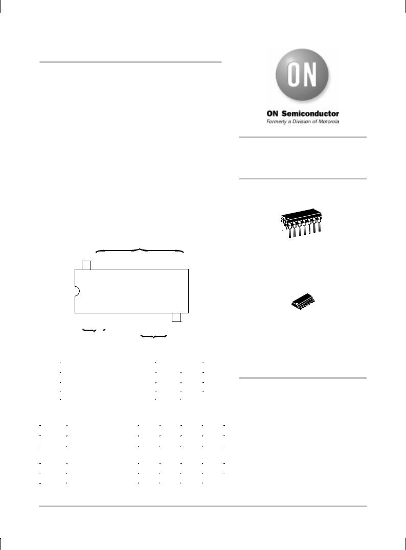
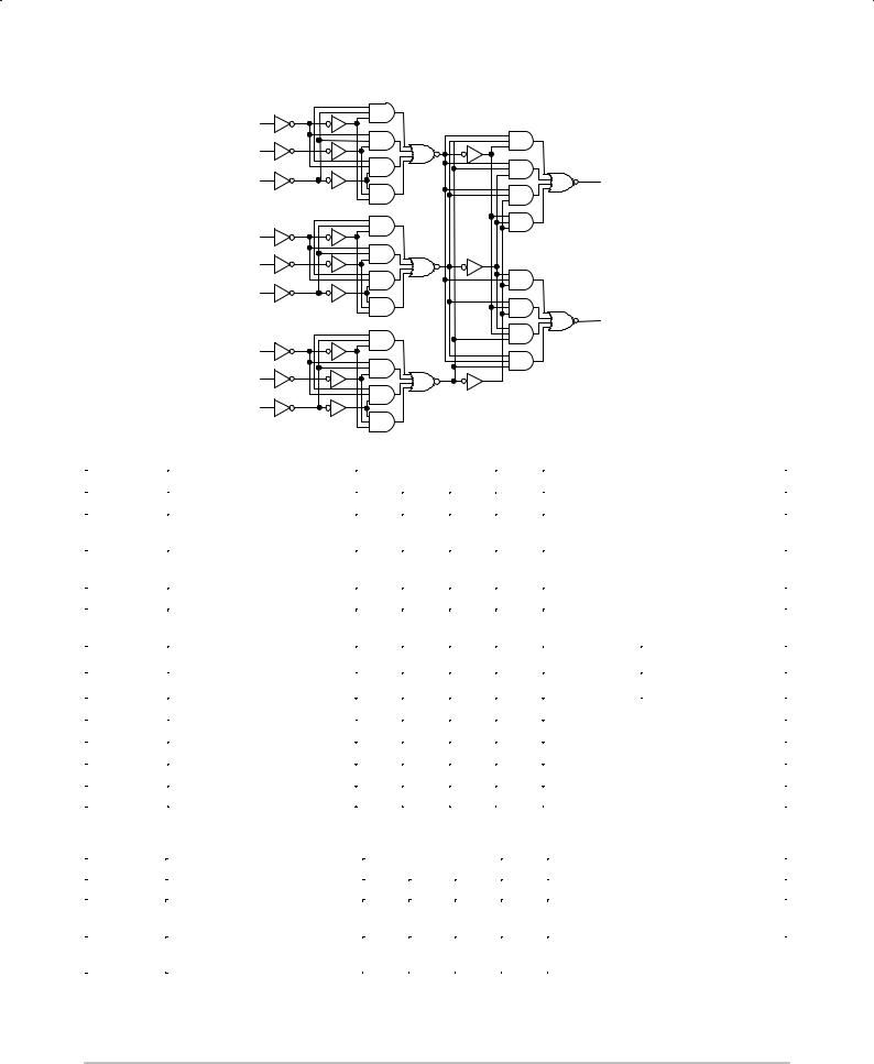
The SN74LS280 is a Universal 9-Bit Parity Generator / Checker. It features odd / even outputs to facilitate either odd or even parity. By cascading, the word length is easily expanded.
The LS280 is designed without the expander input implementation, but the corresponding function is provided by an input at Pin 4 and the absence of any connection at Pin 3. This design permits the LS280 to be substituted for the LS180 which results in improved performance. The LS280 has buffered inputs to lower the drive requirements to one LS unit load.
•Generates Either Odd or Even Parity for Nine Data Lines
•Typical Data-to-Output Delay of only 33 ns
•Cascadable for n-Bits
•Can Be Used To Upgrade Systems Using MSI Parity Circuits
•Typical Power Dissipation = 80 mW
|
|
|
|
|
|
|
|
|
|
|
|
|
|
|
|
|
|
INPUTS |
|
|
|
|
|
|
|
|
|
|
|
||||||||
|
|
|
|
|
|
|
|
|
|
|
|
|
|
|
|
|
|
|
|
|
|
||||||||||||||||
|
|
|
|
|
|
|
|
|
|
|
|
|
|
|
|
|
|
|
|
|
|
||||||||||||||||
|
|
|
VCC |
|
|
|
F |
|
E |
D |
|
|
C |
|
B |
A |
|
||||||||||||||||||||
|
|
14 |
|
|
|
13 |
|
|
12 |
|
11 |
|
|
10 |
|
|
9 |
|
|
|
|
8 |
|
|
|||||||||||||
|
|
|
|
|
|
|
|
|
|
|
|
|
|
|
|
|
|
|
|
|
|
|
|
|
|
|
|
|
|
|
|
|
|
||||
|
|
|
|
|
|
|
|
|
F |
|
E |
D |
|
|
|
C |
|
|
B |
|
|
|
|
|
|||||||||||||
|
|
|
|
|
|
|
|
|
G |
|
|
|
|
|
|
|
|
|
∑ |
|
∑ A |
|
|
|
|
|
|||||||||||
|
|
|
|
|
|
|
|
|
|
|
|
|
|
|
|
|
|
|
|
|
|
||||||||||||||||
|
|
|
|
|
|
|
|
|
H |
|
|
|
|
|
I |
EVEN |
ODD |
|
|
|
|
|
|||||||||||||||
|
|
|
|
|
|
|
|
|
|
|
|
|
|
|
|
|
|
|
|
|
|
|
|
|
|
|
|
|
|
|
|
|
|
|
|
|
|
|
|
|
1 |
|
|
|
2 |
|
|
|
3 |
|
4 |
|
|
5 |
|
|
|
6 |
|
|
|
|
7 |
|
|
||||||||||
|
|
|
G |
|
|
|
H |
|
NC |
I |
|
|
∑ |
|
|
|
∑ |
|
GND |
|
|||||||||||||||||
|
|
|
|
|
|
|
|
|
|
|
|
|
|
|
|
INPUT |
EVEN |
ODD |
|
|
|
|
|||||||||||||||
|
|
|
|
INPUTS |
|
|
|
|
|
|
|
||||||||||||||||||||||||||
|
|
|
|
|
|
|
|
|
|
|
|
|
|
|
|
|
|
|
|
|
|
|
|
|
|
|
|
|
|||||||||
|
|
|
|
|
|
|
|
|
|
|
|
|
|
|
|
|
|
|
|
|
|
|
|
|
|
|
|
||||||||||
|
|
|
|
|
|
|
|
|
|
|
OUTPUTS |
|
|
|
|
||||||||||||||||||||||
|
|
|
|
|
|
|
|
|
|
|
|
|
|
|
|
|
|
|
|
|
|
|
|
|
|||||||||||||
|
|
|
|
|
|
|
|
|
|
|
|
|
FUNCTION TABLE |
|
|
|
|
||||||||||||||||||||
|
|
|
|
|
|
|
|
|
|
|
|
|
|
|
|
|
|||||||||||||||||||||
|
|
NUMBER OF INPUTS A |
|
|
|
|
|
|
|
|
|
|
|
OUTPUTS |
|
||||||||||||||||||||||
|
|
THRU 1 THAT ARE HIGH |
|
|
|
|
|
|
|
∑ EVEN |
∑ ODD |
|
|||||||||||||||||||||||||
|
|
|
|
|
|
|
|
|
|
|
|
|
|
|
|
|
|
|
|
|
|
|
|
|
|
|
|||||||||||
|
|
|
|
|
|
0, 2, 4, 6, 8 |
|
|
|
|
|
|
|
|
|
|
|
|
|
|
|
H |
|
|
L |
|
|||||||||||
|
|
|
|
|
|
1, 3, 5, 7, 9 |
|
|
|
|
|
|
|
|
|
|
|
|
|
|
|
L |
|
|
H |
|
|||||||||||
|
|
|
|
|
|
|
|
|
|
|
|
|
|
|
|
|
|
|
|
|
|
|
|
||||||||||||||
|
H = HIGH Level, L = LOW Level |
|
|
|
|
|
|
|
|
|
|
|
|
|
|
|
|
|
|
|
|
|
|||||||||||||||
GUARANTEED OPERATING RANGES |
|
|
|
|
|
|
|
|
|
|
|
||||||||||||||||||||||||||
|
|
|
|
|
|
|
|
|
|
|
|
|
|
|
|
|
|
|
|
||||||||||||||||||
Symbol |
|
|
|
Parameter |
|
|
|
|
|
Min |
|
|
|
|
Typ |
|
|
Max |
Unit |
||||||||||||||||||
|
|
|
|
|
|
|
|
|
|
|
|||||||||||||||||||||||||||
VCC |
Supply Voltage |
|
|
|
4.75 |
|
5.0 |
|
|
5.25 |
V |
||||||||||||||||||||||||||
TA |
Operating Ambient |
|
|
|
0 |
|
|
|
25 |
|
|
70 |
°C |
||||||||||||||||||||||||
|
|
Temperature Range |
|
|
|
|
|
|
|
|
|
|
|
|
|
|
|
|
|
|
|
|
|
||||||||||||||
|
|
|
|
|
|
|
|
|
|
|
|
|
|
|
|
|
|
|
|
|
|
||||||||||||||||
IOH |
Output Current ± High |
|
|
|
|
|
|
|
|
|
|
|
|
|
|
|
|
|
|
|
± 0.4 |
mA |
|||||||||||||||
IOL |
Output Current ± Low |
|
|
|
|
|
|
|
|
|
|
|
|
|
|
|
|
|
|
|
8.0 |
mA |
|||||||||||||||
http://onsemi.com
LOW
POWER
SCHOTTKY
14 
1
PLASTIC
N SUFFIX
CASE 646
14
1
SOIC
D SUFFIX
CASE 751A
ORDERING INFORMATION
Device |
Package |
Shipping |
|
|
|
SN74LS280N |
14 Pin DIP |
2000 Units/Box |
|
|
|
SN74LS280D |
14 Pin |
2500/Tape & Reel |
|
|
|
Semiconductor Components Industries, LLC, 1999 |
1 |
Publication Order Number: |
December, 1999 ± Rev. 6 |
|
SN74LS280/D |

SN74LS280
FUNCTIONAL BLOCK DIAGRAM
A |
(8) |
|
|
B |
(9) |
|
|
C |
(10) |
(5) |
∑ |
|
|
|
EVEN |
D |
(11) |
|
|
E |
(12) |
|
|
F |
(13) |
|
|
|
|
(6) |
∑ |
|
|
|
ODD |
G |
(1) |
|
|
H |
(2) |
|
|
I |
(4) |
|
|
DC CHARACTERISTICS OVER OPERATING TEMPERATURE RANGE (unless otherwise specified)
|
|
|
Limits |
|
|
|
|
|
|
|
|
|
|
|
|
|
|
Symbol |
Parameter |
Min |
Typ |
Max |
Unit |
|
Test Conditions |
|
|
|
|
|
|
|
|
|
|
VIH |
Input HIGH Voltage |
2.0 |
|
|
V |
Guaranteed Input HIGH Voltage for |
||
|
|
All Inputs |
|
|
||||
VIL |
Input LOW Voltage |
|
|
0.8 |
V |
Guaranteed Input LOW Voltage for |
||
|
|
|
All Inputs |
|
|
|||
VIK |
Input Clamp Diode Voltage |
|
± 0.65 |
± 1.5 |
V |
VCC = MIN, IIN = ± 18 mA |
||
VOH |
Output HIGH Voltage |
2.7 |
3.5 |
|
V |
VCC = MIN, IOH = MAX, VIN = VIH |
||
|
or VIL per Truth Table |
|||||||
|
|
|
|
|
|
|||
|
|
|
0.25 |
0.4 |
V |
I = 4.0 mA |
|
VCC = VCC MIN, |
VOL |
Output LOW Voltage |
|
|
|
|
OL |
|
VIN = VIL or VIH |
|
0.35 |
0.5 |
V |
IOL = 8.0 mA |
|
|||
|
|
|
|
per Truth Table |
||||
|
|
|
|
|
|
|
|
|
IIH |
Input HIGH Current |
|
|
20 |
μA |
VCC = MAX, VIN = 2.7 V |
||
|
|
0.1 |
mA |
VCC = MAX, VIN = 7.0 V |
||||
|
|
|
|
|||||
IIL |
Input LOW Current |
|
|
± 0.4 |
mA |
VCC = MAX, VIN = 0.4 V |
||
IOS |
Short Circuit Current (Note 1) |
± 20 |
|
± 100 |
mA |
VCC = MAX |
|
|
ICC |
Power Supply Current |
|
|
27 |
mA |
VCC = MAX |
|
|
Note 1: Not more than one output should be shorted at a time, nor for more than 1 second.
AC CHARACTERISTICS (TA = 25°C, VCC = 5.0 V)
|
|
|
Limits |
|
|
|
Symbol |
Parameter |
|
|
|
Unit |
Test Conditions |
Min |
Typ |
Max |
||||
|
|
|
|
|
|
|
tPLH |
Propagation Delay, Data to Output |
|
33 |
50 |
ns |
|
tPHL |
ΣEVEN |
|
29 |
45 |
|
|
|
|
CL = 15 pF |
||||
tPLH |
Propagation Delay, Data to Output |
|
23 |
35 |
ns |
|
|
|
|||||
tPHL |
ΣODD |
|
31 |
50 |
|
|
|
|
|
http://onsemi.com
2
 Loading...