


Motorola MPX2700GP, MPX2700GS, MPX2700GSX, MPX2700D, MPX2700GVSX Datasheet
...
MOTOROLA
SEMICONDUCTOR TECHNICAL DATA
Order this document by MPX2700/D
700 |
kPa |
|
High |
Pressure, |
Temperature |
Compensated & |
Calibrated |
|
Silicon Pressure |
Sensors |
|
The MPX2700 series device is a silicon piezoresistive pressure sensor providing a highly accurate and linear voltage output Ð directly proportional to the applied pressure. The sensor is a single monolithic silicon diaphragm with the strain gauge and a thin±film resistor network integrated on±chip. The sensor is laser trimmed for precise span and offset calibration and temperature compensation.
Features
•Unique Silicon Shear Stress Strain Gauge
•±0.5% Linearity
•Easy to Use Chip Carrier Package
•Basic Element, Single and Dual Ported Devices Available
•Available in Absolute, Differential and Gauge configurations
Application Examples
•Pump/Motor Controllers
•Pneumatic Control
•Tire Pressure Gauges
•Robotics
•Medical Diagnostics
•Pressure Switching
•Hydraulics
Figure 1 shows a block diagram of the internal circuitry on the stand±alone pressure sensor chip.
|
VS |
|
|
|
|
3 |
|
|
|
|
THIN FILM |
2 |
|
|
X±ducer |
TEMPERATURE |
Vout+ |
||
COMPENSATION |
|
|||
SENSING |
|
|
||
AND |
|
|
||
ELEMENT |
4 |
Vout± |
||
CALIBRATION |
||||
|
|
|||
|
CIRCUITRY |
|
|
|
|
1 |
|
|
|
|
GND |
|
|
MPX2700
SERIES
0 to 700 kPa (0 to 100 psi)
40 mV FULL SCALE SPAN (TYPICAL)
BASIC CHIP
CARRIER ELEMENT
CASE 344±15, STYLE 1
DIFFERENTIAL
PORT OPTION
CASE 344C±01, STYLE 1
NOTE: Pin 1 is the notched pin.
PIN NUMBER
1 |
Gnd |
3 |
VS |
2 |
+Vout |
4 |
±Vout |
Figure 1. Temperature Compensated Pressure Sensor Schematic
VOLTAGE OUTPUT versus APPLIED DIFFERENTIAL PRESSURE
The differential voltage output of the X±ducer is directly proportional to the differential pressure applied.
The output voltage of the differential or gauge sensor increases with increasing pressure applied to the pressure side (P1) relative to the vacuum side (P2). Similarly, output voltage increases as increasing vacuum is applied to the vacuum side (P2) relative to the pressure side (P1). This sensor is designed for applications where P1 is always greater than, or equal to P2.
Senseon and X±ducer are trademarks of Motorola, Inc.
REV 2
Motorola Sensor Device Data |
1 |
Motorola, Inc. 1997 |
|

MPX2700 SERIES
MAXIMUM RATINGS
Rating |
|
Symbol |
|
|
|
Value |
|
Unit |
||||
|
|
|
|
|
|
|
|
|
|
|
|
|
Overpressure(8) (P2 v 1 Atmosphere) |
|
P1max |
|
|
|
2800 |
|
|
kPa |
|||
Burst Pressure(8) (P2 v 1 Atmosphere) |
|
P1 |
|
|
|
5000 |
|
|
kPa |
|||
|
|
burst |
|
|
|
|
|
|
|
|
|
|
Storage Temperature |
|
Tstg |
|
|
± 40 to +125 |
|
°C |
|||||
Operating Temperature |
|
TA |
|
|
± 40 to +125 |
|
°C |
|||||
OPERATING CHARACTERISTICS (VCC = 10 Vdc, TA = 25°C unless otherwise noted. P1 w P2; P2 v 1 Atmosphere.) |
|
|
|
|||||||||
Characteristic |
|
Symbol |
|
Min |
|
Typ |
|
Max |
|
|
Unit |
|
|
|
|
|
|
|
|
|
|
|
|
|
|
Pressure Range(1) |
|
P |
0 |
Ð |
|
700 |
|
|
kPa |
|||
|
|
OP |
|
|
|
|
|
|
|
|
|
|
Supply Voltage(2) |
|
VS |
Ð |
10 |
|
16 |
|
|
Vdc |
|||
Supply Current |
|
Io |
Ð |
6.0 |
|
Ð |
|
|
mAdc |
|||
Full Scale Span(3) |
|
V |
38.5 |
40 |
|
41.5 |
|
|
mV |
|||
|
|
FSS |
|
|
|
|
|
|
|
|
|
|
Offset(4) |
|
Voff |
±1.0 |
Ð |
|
1.0 |
|
|
mV |
|||
Sensitivity |
|
V/ P |
Ð |
0.057 |
|
Ð |
|
|
mV/kPa |
|||
|
|
|
|
|
|
|
|
|
|
|
|
|
Linearity(5) |
|
Ð |
± 0.5 |
Ð |
|
0.5 |
|
|
%VFSS |
|||
Pressure Hysteresis(5) (0 to 700 kPa) |
|
Ð |
Ð |
± 0.1 |
|
Ð |
|
|
%V |
|||
|
|
|
|
|
|
|
|
|
|
|
|
FSS |
Temperature Hysteresis(5) (± 40°C to +125°C) |
|
Ð |
Ð |
± 0.5 |
|
Ð |
|
|
%V |
|||
|
|
|
|
|
|
|
|
|
|
|
|
FSS |
Temperature Effect on Full Scale Span(5) |
|
TCV |
±1.0 |
Ð |
|
1.0 |
|
|
%V |
|||
|
|
FSS |
|
|
|
|
|
|
|
|
|
FSS |
Temperature Effect on Offset(5) |
|
TCVoff |
±1.0 |
Ð |
|
1.0 |
|
|
mV |
|||
Input Impedance |
|
Zin |
1300 |
Ð |
|
4000 |
|
|
Ω |
|||
Output Impedance |
|
Zout |
1400 |
Ð |
|
3000 |
|
|
Ω |
|||
Response Time(6) (10% to 90%) |
|
tR |
Ð |
1.0 |
|
Ð |
|
|
ms |
|||
Warm±Up(7) |
|
Ð |
Ð |
20 |
|
Ð |
|
|
ms |
|||
MECHANICAL CHARACTERISTICS |
|
|
|
|
|
|
|
|
|
|
|
|
|
|
|
|
|
|
|
|
|
|
|
|
|
Characteristic |
|
Symbol |
|
|
Min |
|
Typ |
|
Max |
|
|
Unit |
|
|
|
|
|
|
|
|
|
|
|
|
|
Weight (Basic Element Case 344±15) |
|
Ð |
|
Ð |
|
2.0 |
|
Ð |
|
|
Grams |
|
|
|
|
|
|
|
|
|
|
|
|
|
|
NOTES: |
|
|
|
|
|
|
|
|
|
|
|
|
1.1.0 kPa (kiloPascal) equals 0.145 psi.
2.Device is ratiometric within this specified excitation range. Operating the device above the specified excitation range may induce additional error due to device self±heating.
3.Full Scale Span (VFSS) is defined as the algebraic difference between the output voltage at full rated pressure and the output voltage at the minimum rated pressure.
4.Offset (Voff) is defined as the output voltage at the minimum rated pressure.
5.Accuracy (error budget) consists of the following:
• |
Linearity: |
Output deviation from a straight line relationship with pressure, using end point method, over the specified |
|
|
pressure range. |
• |
Temperature Hysteresis: |
Output deviation at any temperature within the operating temperature range, after the temperature is |
|
|
cycled to and from the minimum or maximum operating temperature points, with zero differential pressure |
|
|
applied. |
• |
Pressure Hysteresis: |
Output deviation at any pressure within the specified range, when this pressure is cycled to and from the |
|
|
minimum or maximum rated pressure, at 25°C. |
• |
TcSpan: |
Output deviation at full rated pressure over the temperature range of 0 to 85°C, relative to 25°C. |
• |
TcOffset: |
Output deviation with minimum rated pressure applied, over the temperature range of 0 to 85°C, relative |
|
|
to 25°C. |
6.Response Time is defined as the time for the incremental change in the output to go from 10% to 90% of its final value when subjected to a specified step change in pressure.
7.Warm±up is defined as the time required for the device to meet the specified output voltage after the pressure has been stabilized.
8.Basic Element only, Case 344±15.
9.P2 max : 500 kPa.
2 |
Motorola Sensor Device Data |
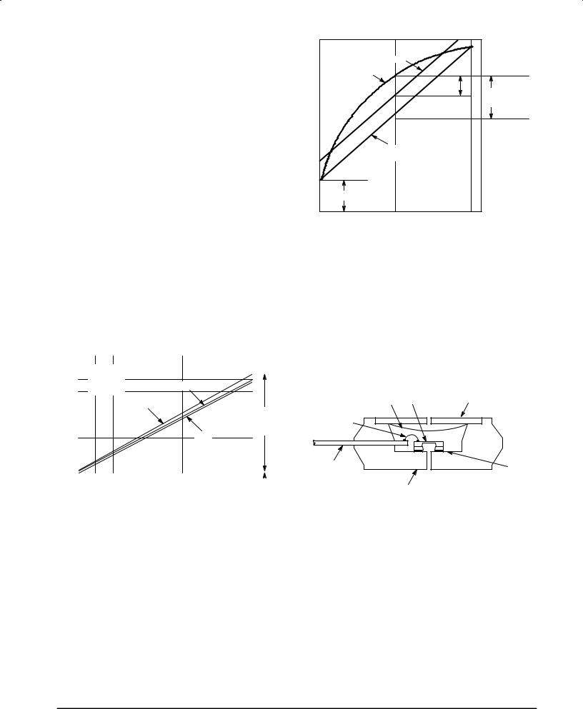
LINEARITY
Linearity refers to how well a transducer's output follows the equation: Vout = Voff + sensitivity x P over the operating pressure range. There are two basic methods for calculating nonlinearity: (1) end point straight line fit or (2) a least squares best line fit (see Figure 3). While a least squares fit gives the ªbest caseº linearity error (lower numerical value), the calculations required are burdensome.
Conversely, an end point fit will give the ªworst caseº error (often more desirable in error budget calculations) and the calculations are more straightforward for the user. Motorola's specified pressure sensor linearities are based on the end point straight line method measured at the midrange pressure.
|
|
MPX2700 |
SERIES |
|
|
LEAST SQUARES FIT |
|
|
|
OUTPUT |
EXAGGERATED |
|
|
|
PERFORMANCE |
|
|
|
|
CURVE |
LEAST |
STRAIGHT LINE |
||
|
||||
|
DEVIATION |
|||
VOLTAGE |
|
|||
|
SQUARE |
|||
|
|
|
||
|
DEVIATION |
|
|
|
|
|
|
|
|
RELATIVE |
END POINT |
|
|
|
STRAIGHT LINE FIT |
|
|
||
|
|
|
|
|
|
OFFSET |
|
|
|
0 |
50 |
|
100 |
|
PRESSURE (% FULLSCALE)
Figure 2. Linearity Specification Comparison
ON±CHIP TEMPERATURE COMPENSATION and CALIBRATION
Figure 3 shows the output characteristics of the MPX2700 series at 25°C. The output is directly proportional to the differential pressure and is essentially a straight line.
The effects of temperature on Full±Scale Span and Offset are very small and are shown under Operating Characteristics.
|
50 |
|
|
|
|
|
|
|
|
|
|
|
|
|
|
|
|
|
|
|
|
|
|
|
|
|
|
|
|
|
|
|
|
|
|
|
|
|
|
|
|
|
|
|
|
|
|
|
40 |
|
VS = 10 V |
|
|
|
|
|
|
|
|
|
|
|
|
|
|
|
|
|
|
|
|
|
|
|
|
||||
|
|
TA |
= 25°C |
|
|
TYP |
|
|
|
|
|
|
|
|
|
(mV) |
|
|
P1 > P2 |
|
|
|
|
|
|
|
|
|
|
||
30 |
|
|
|
|
|
|
|
|
|
|
|
|
|||
|
|
|
|
|
|
|
|
|
|
|
|
|
|
||
|
|
|
MAX |
|
|
|
|
|
|
|
|
|
|
||
OUTPUT |
|
|
|
|
|
|
|
|
|
|
SPAN |
||||
|
|
|
|
|
|
|
|
|
|
|
|
||||
|
20 |
|
|
|
|
|
|
|
|
|
|
RANGE |
|||
|
|
|
|
|
|
|
MIN |
|
|
|
(TYP) |
||||
|
|
|
|
|
|
|
|
|
|
|
|||||
|
10 |
|
|
|
|
|
|
|
|
|
|
|
|
|
|
|
|
|
|
|
|
|
|
|
|
|
|
|
|
|
|
|
|
|
|
|
|
|
|
|
|
|
|
|
|
|
|
|
0 |
|
|
|
|
|
|
|
|
|
|
|
|
|
|
|
|
|
|
|
|
|
|
|
|
|
|
|
|
|
|
|
|
|
|
|
|
|
|
|
|
|
|
|
|
|
|
|
± 5 |
|
PSI |
20 |
40 |
60 |
80 |
100 |
|
|
|
||||
|
|
kPa |
140 |
280 |
420 |
560 |
700 |
|
OFFSET |
||||||
|
|
|
|||||||||||||
Figure 3. Output versus Pressure Differential
SILICONE |
|
|
STAINLESS STEEL |
DIE COAT |
DIE |
|
|
|
METAL COVER |
||
|
|
P1 |
|
|
|
|
|
WIRE BOND |
|
|
|
LEAD |
|
|
RTV DIE |
|
|
BOND |
|
FRAME |
|
P2 |
|
|
|
EPOXY CASE
Figure 4. Cross±Section of Differential Pressure Sensor Die in Its Basic Package (Not to Scale)
Figure 4 shows the cross section of the Motorola MPX pressure sensor die in the chip carrier package. A silicone gel isolates the die surface and wire bonds from the environment, while allowing the pressure signal to be transmitted to the silicon diaphragm. MPX2700 series pressure sensor operating characteristics and internal reli-
ability and qualification tests are based on use of dry air as the pressure media. Media other than dry air may have adverse effects on sensor performance and long term reliability. Contact the factory for information regarding media compatibility in your application.
Motorola Sensor Device Data |
3 |
 Loading...