


MELDAS is a registered trademark of Mitsubishi Electric Corporation.
Other company and product names that appear in this manual are trademarks or registered trademarks of the respective companies.

Introduction
This manual is an instruction manual for NAVI MILL for 700/70 (hereafter NAVI MILL).
This manual explains how to operate NAVI MILL, so read this manual thoroughly before use. Be sure to study "Precautions for Safety" on the next page and use the system safely.
Details described in this manual
 CAUTION
For items described as "Restrictions" or "Usable State" in this manual, the instruction manual issued by the machine tool builder takes precedence over this manual.
Items not described in this manual must be interpreted as "not possible".
This manual is written on the assumption that all option functions are added. Confirm with the specifications issued by the machine tool builder before starting to use.
Refer to the Instruction Manual issued by each machine tool builder for details on each machine tool.
Some screens and functions may differ depending on the NC system (or its version), and some functions may not be possible. Please confirm the specifications before use.
Refer to the following documents. MITSUBISHI CNC 700/70 Series MITSUBISHI CNC 700/70 Series MITSUBISHI CNC 700/70 Series
Instruction Manual .................................... |
IB-1500042 |
Setup Manual ........................................... |
IB-1500124 |
Programming Manual (M system) ............ |
IB-1500072 |
Precautions for Safety
Always read the specifications issued by the machine tool builder, this manual, related manuals and attached documents before operation or programming to ensure correct use.
Understand the NAVI MILL, safety items and cautions before using the system.
This manual ranks the safety precautions into "DANGER", "WARNING" and "CAUTION".
DANGER |
When the user may be subject to imminent fatalities or major |
|
injuries if handling is mistaken. |
||
|
When the user may be subject to fatalities or major injuries if |
|
WARNING |
||
handling is mistaken. |
||
|
||
|
When the user may be subject to bodily injury or when property |
|
CAUTION |
||
damage may occur if handling is mistaken. |
Note that even items ranked as " CAUTION", may lead to serious consequences depending on the situation. In any case, important information that must always be observed is described.
 DANGER
Not applicable in this manual.
 WARNING
1. Items related to operation
If the operation start position is set in a block which is in the middle of the program and the program is started, the program before the set block is not executed. Please confirm that G and F modal and coordinate values are appropriate. If there are coordinate system shift commands or M, S, T and B commands before the block set as the start position, carry out the required commands using the MDI, etc. If the program is run from the set block without carrying out these operations, there is a danger of interference with the machine or of machine operation at an unexpected speed, which may result in breakage of tools or machine tool or may cause damage to the operators.
Under the constant surface speed control (during G96 modal), if the axis targeted for the constant surface speed control moves toward the spindle center, the spindle rotation speed will increase and may exceed the allowable speed of the workpiece or chuck, etc. In this case, the workpiece, etc. may jump out during machining, which may result in breakage of tools or machine tool or may cause damage to the operators.
 CAUTION
1. Items related to product and manual
For items described as "Restrictions" or "Usable State" in this manual, the instruction manual issued by the machine tool builder takes precedence over this manual.
Items not described in this manual must be interpreted as "not possible".
This manual is written on the assumption that all option functions are added. Confirm with the specifications issued by the machine tool builder before starting use.
Refer to the Instruction Manual issued by each machine tool builder for details on each machine tool.
Some screens and functions may differ depending on the NC system (or its version), and some functions may not be possible. Please confirm the specifications before use.
(Continued on next page)

 CAUTION
2. Items related to installation and assembly
Ground the signal cables to ensure stable system operation. Also ground the NC unit main frame, power distribution panel and machine to one point, so they all have the same potential.
3. Items related to preparation before use
Always set the stored stroke limit. Failure to set this could result in collision with the machine end.
Always turn the power OFF before connecting/disconnecting the I/O device cable. Failure to do so could damage the I/O device and NC unit.
4. Items related to screen operation
NAVI MILL uses the following variables in order to operate the NC program.
NC program mode |
Variables used by NAVI MILL |
User macro mode |
#150 to #179 |
MTB macro mode |
#450 to #479 |
When NC program mode is user macro mode, do not use common variables. If those variables are written over, malfunction will be resulted. If mistakenly written them over, turn the NC power OFF after securing your safety. When the power is turned ON again, the system recovers the data.
NC program mode is specified on the Preferences screen.
When either "TOOL REG No." or "HOLE CYCLE" is input in the hole drilling screen, the feedrate and spindle speed are automatically determined using the data in the tool file screen and the cutting condition file screen. In the same way, when "TOOL REG No." is input in the face cutting screen, the contour cutting screen and the pocket screen, the feedrate and spindle speed are automatically determined. Note that the feedrate and spindle speed of each process determined once will not be changed by changing the data in the tool file screen and the cutting condition file screen.
5. Items related to operation
Stay out of the moveable range of the machine during automatic operation. During rotation, keep hands, feet and face away from the spindle.
Carry out dry operation before actually machining, and confirm the machining program, tool offset and workpiece coordinate system offset.
If the operation start position is set from a block in the program and the program is started, the program before the set block is not executed. If there are coordinate system shift commands or M, S, T, and B commands before the block set as the starting position, carry out the required commands using the MDI, etc. There is a danger of interference with the machine if the operation is started from the set starting position block without carrying out these operations.
Program so the mirror image function is turned ON/OFF at the mirror image center. The mirror image center will deviate if the function is turned ON/OFF at a position other than the mirror image center.
(Continued on next page)
 CAUTION
6. Items related to faults and abnormalities
If the battery low warning is issued, save the machining programs, tool data and parameters in an input/output device, and then replace the battery. When the battery alarm is issued, the machining programs, tool data and parameters may be destroyed. Reload the data after replacing the battery.
If the axis overruns or emits an abnormal noise, immediately press the emergency stop button and stop the axis movement.
7. Items related to maintenance
Incorrect connections may damage the devices, so connect the cables to the specified connectors.
Do not apply voltages other than those indicated according to specification on the connector. Doing so may lead to destruction or damage.
Do not connect or disconnect the connection cables between each unit while the power is ON.
Do not connect or disconnect the PCBs while the power is ON.
Do not connect the cable by pulling on the cable wire.
Do not short circuit, charge, overheat, incinerate or disassemble the battery.
Dispose the spent battery according to local laws.
Dispose the spent cooling fan according to local laws.
Do not replace the control unit while the power is ON.
Do not replace the operation panel I/O unit while the power is ON.
Do not replace the control section power supply PCB while the power is ON.
Do not replace the expansion PCB while the power is ON.
Do not replace the memory cassette while the power is ON.
Do not replace the cooling fan while the power is ON.
Do not replace the battery while the power is ON.
Be careful that metal cutting chips, etc., do not come into contact with the connector contacts of the memory cassette.
Do not replace the high-speed program server unit while the power is ON.
Disposal
(Note) This symbol mark is for EU countries only.
This symbol mark is according to the directive 2006/66/EC Article 20 Information for endusers and Annex II.
Your MITSUBISHI ELECTRIC product is designed and manufactured with high quality materials and components which can be recycled and/or reused.
This symbol means that batteries and accumulators, at their end-of-life, should be disposed of separately from your household waste.
If a chemical symbol is printed beneath the symbol shown above, this chemical symbol means that the battery or accumulator contains a heavy metal at a certain concentration. This will be indicated as follows:
Hg: mercury (0,0005%), Cd: cadmium (0,002%), Pb: lead (0,004%)
In the European Union there are separate collection systems for used batteries and accumulators. Please, dispose of batteries and accumulators correctly at your local community waste collection/ recycling centre.
Please, help us to conserve the environment we live in!
|
Contents |
|
1. OUTLINE ..................................................................................................................... |
1 |
|
1.1 |
System Outline ............................................................................................................ |
1 |
1.2 |
Input Procedures ......................................................................................................... |
2 |
1.3 |
Screen Configuration................................................................................................... |
3 |
1.4 |
Starting NAVI MILL...................................................................................................... |
4 |
1.5 |
Setting up NAVI MILL .................................................................................................. |
5 |
2. FUNCTIONS OF DISPLAY AREA ............................................................................... |
7 |
|
2.1 |
LIST VIEW Area .......................................................................................................... |
8 |
2.2 OPERATION VIEW Area........................................................................................... |
10 |
|
2.3 |
Setting Area............................................................................................................... |
11 |
2.4 |
Message Area ........................................................................................................... |
11 |
2.5 |
Menu Display Area .................................................................................................... |
11 |
3. BASIC OPERATIONS................................................................................................ |
12 |
|
3.1 |
Changing Active View................................................................................................ |
12 |
3.2 |
Changing Screen....................................................................................................... |
12 |
3.3 |
Setting Data............................................................................................................... |
14 |
3.4 |
Switching Windows.................................................................................................... |
17 |
3.5 |
Switching Selection Tags .......................................................................................... |
17 |
3.6 |
Inputting Operations .................................................................................................. |
18 |
4. SCREEN SPECIFICATIONS ..................................................................................... |
19 |
|
4.1 |
Starting NAVI MILL.................................................................................................... |
19 |
4.2 |
Screen Related to the Program ................................................................................. |
20 |
|
4.2.1 Program Edit Screen .................................................................................. |
20 |
4.3 |
Screens Related to the Process Edit Functions ........................................................ |
24 |
|
4.3.1 Process List Screen.................................................................................... |
24 |
|
4.3.2 Multiple Parts Screen.................................................................................. |
26 |
|
4.3.3 Operating Process ...................................................................................... |
30 |
|
4.3.4 Process Mode Selection Screen................................................................. |
36 |
|
4.3.5 Initial Condition Setting ............................................................................... |
39 |
|
4.3.6 Hole Drilling ................................................................................................ |
43 |
|
4.3.7 Face Cutting ............................................................................................... |
55 |
|
4.3.8 Contour Cutting........................................................................................... |
59 |
|
4.3.9 Pocket......................................................................................................... |
69 |
|
4.3.10 EIA Screen................................................................................................ |
78 |
4.4 |
Screens Related to File Editing ................................................................................. |
79 |
|
4.4.1 Tool File Screen.......................................................................................... |
79 |
|
4.4.2 Cutting Condition File Screen ..................................................................... |
81 |
4.5 |
Screen Related to the Parameters ............................................................................ |
83 |
|
4.5.1 Parameter Screen....................................................................................... |
83 |
|
4.5.2 PREFERENCE Screen............................................................................... |
86 |
4.6 |
Screen Related to the Version................................................................................... |
88 |
|
4.6.1 Version Screen ........................................................................................... |
88 |
4.7 |
Program Checker Screen .......................................................................................... |
89 |
4.8 |
Guidance Function .................................................................................................... |
94 |
|
4.8.1 Tool Guidance Screen ................................................................................ |
95 |
5. PROGRAM SPECIFICATIONS.................................................................................. |
96 |
||
5.1 |
NC Program............................................................................................................... |
97 |
|
|
5.1.1 Output Method for NC Program.................................................................. |
97 |
|
|
5.1.2 Restrictions ............................................................................................... |
100 |
|
5.2 |
File Program ............................................................................................................ |
101 |
|
5.3 |
Parameter Program ................................................................................................. |
101 |
|
5.4 |
Macro Program........................................................................................................ |
101 |
|
6. TOOL FUNCTIONS ................................................................................................. |
102 |
||
6.1 Tool Change Command (M6) and T-Command ...................................................... |
102 |
||
6.2 |
Editing Tool Number and Next Tool Number........................................................... |
103 |
|
7. RESTRICTIONS FOR CNC FUNCTION SPECIFICATIONS................................... |
104 |
||
8. ALARM MESSAGE.................................................................................................. |
105 |
||
8.1 |
Error Message ......................................................................................................... |
105 |
|
8.2 |
Warning Message.................................................................................................... |
108 |
|
8.3 |
Operation Message ................................................................................................. |
109 |
|
APPENDIX 1. VARIABLES USED IN NAVI MILL ........................................................ |
110 |
||
APPENDIX 2. PROGRAMMING EXAMPLE ................................................................ |
112 |
||
Appendix 2.1 |
Machining Drawing ............................................................................... |
112 |
|
Appendix 2.2 |
Process Table ....................................................................................... |
113 |
|
Appendix 2.3 |
Condition Setting................................................................................... |
113 |
|
Appendix 2.4 |
Creating Program.................................................................................. |
114 |
|

1. OUTLINE
1.1 System Outline
1. OUTLINE
1.1 System Outline
This manual is an instruction manual for NAVI MILL for 700/70 (hereafter NAVI MILL).
The part program for the vertical machining center (three axes of X, Y and Z) is created with the NAVI MILL.
(1)The following machining processes can be edited.
•Hole drilling (Drilling, pecking, step, boring, tapping, helical boring)
•Face cutting (Circle, square)
•Contour cutting (Circle, square, free)
•Pocket machining (Circle, square, L pattern, U pattern, track)
•EIA
(2)The tool file and the cutting condition file are provided and the cutting conditions are determined automatically.
(3)The operation screen consists of the LIST VIEW area and the OPERATION VIEW area. In the LIST VIEW area, the whole part program can be always viewed. In the OPERATION VIEW area, there are the guide drawings related to the input items, and the data can be easily input by using these guide drawings.
[LIST VIEW area]
The object of the NAVI MILL is selected.
[OPERATION VIEW area] The screen is displayed
corresponding to the object selected in the LIST VIEW.
[Cutting conditions automatically determined]
Upon tool registration No. entry, the cutting conditions for each process are automatically determined based on the tool file and cutting condition file.
[Help]
[Guide drawing]
 [Menu keys]
(Note) The operation screen size is fixed to 800(width) x 600(length).
(4)Program Checker enables the tool paths of a part program to be graphically traced. With this function, errors in input data can be detected at an earlier stage.
(5)Guidance function provides an operator with error recovery information.
(6)Part program is a macro-program-based NC program. Commands can be added between processes from the edit screen of the standard MELDAS 700/70 Series.
(7)The macro program mentioned above can be customized by the machine tool builder.
-1 -
1. OUTLINE
1.2 Input Procedures
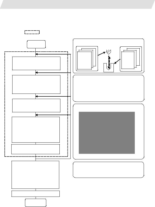
1.2 Input Procedures
The input procedure for the NAVI MILL is shown below.
The part is operated on the NAVI MILL’s screen.
Start
File edition
Tool file
Cutting condition file
Parameter setting
Parameter file
(The parameter setting is valid even if the parameter is set after editing the NC program)
NC program selection
Newly create
Read out
Process editing:
Initial conditions Process mode selection Process data input
Hole drilling / Face cutting / Contour cutting / Pocket machining / EIA, etc.
Program check (Note) Set the tool
compensation amount and workpiece coordinate system offset to perform Program Check. This function is realized by using the 700/70 Series graphic check function.
NC program operation
Supplements
Tool file |
|
Cut condition file |
(Tool registration No. 1 to 99) |
(Work registration No.1 to 8) |
|
|
99 |
8 |
Tool leng. offset |
Material |
|
1 |
|
1 |
Tool leng. offset No. |
Tool applicable |
|
Tool leng. offset |
|
Material |
No. |
: rotation rate |
|
Tool diam. ffset |
||
No. |
No. |
Tool applicable |
Tool diam. offset |
: |
|
|
rotation rate |
|
Spindle rotation |
: |
|
No. |
|
|
direction |
|
|
Spindle rotation |
|
|
direction |
|
|
: |
|
|
Parameter setting
•M0 output • M6 output • M19 output •Next tool preparation, etc.
•Common parameters for hole drilling process (Z clearance, tap selection)
•Common parameters for face cutting process (XYZ clearance, Z approach G code)
•Common parameters for contour cutting / pocket machining process
Process editing
The NC program, tool file, cutting condition file and parameter file transferred to the CNC can be edited on Magicpro-NAVI MILL for 60S.
END
- 2 -

1. OUTLINE
1.3 Screen Configuration
1.3 Screen Configuration
The screen configuration for the MILL NAVI is shown below.
|
Program |
|
|
|
Program |
edit |
|
|
|
|
screen |
|
|
|
|
Process list |
Multiple |
|
|
|
parts |
|
||
|
screen |
|
||
|
screen |
|
||
|
|
|
||
|
Initial |
Hole |
Machining |
|
|
condition |
drilling |
pattem |
|
|
setting screen |
screen |
screen |
|
|
|
Face |
|
|
|
Process |
cutting |
Cutting |
|
|
screen |
|||
Process |
mode select |
condition |
||
Contour |
||||
|
screen |
screen |
||
|
|
cutting |
|
|
|
(For a new process, |
screen |
|
|
|
|
|
||
|
select the process |
|
||
|
form the process |
screen |
|
|
|
mode.) |
|
|
|
|
|
EIA |
|
|
|
Program |
screen |
|
|
|
|
|
||
|
checker |
|
|
|
|
Tool file |
|
|
|
File |
screen |
|
|
|
Cutting |
|
|
||
|
|
|
||
|
condition |
|
|
|
|
file screen |
|
|
|
Parameter |
Parameter |
Preference |
|
|
screen |
screen |
|
||
|
|
|||
Version |
Version |
|
|
|
screen |
|
|
||
|
|
|
- 3 -

1. OUTLINE
|
1.3 Screen Configuration |
|
|
|
|
Screen name |
Details |
|
Title screen |
This screen is displayed when the power is turned ON. |
|
Program edit screen |
The process program is read out and saved, etc. |
|
Process list screen |
Tool information and cutting conditions for each |
|
|
process of a machining program are listed. |
|
Multiple parts screen |
A NC program for the multiple parts machining is |
|
|
generated. |
|
Process mode select |
The process mode (hole drilling, etc.) is selected. |
|
screen |
|
|
Initial conditions setting |
The initial conditions for the process program are set. |
|
screen |
|
|
Hole drilling screen |
The parameters for the hole drilling process are input. |
|
Hole drilling machining |
The parameters related to the machining pattern of the |
|
pattern screen |
hole drilling process are input. |
|
Cutting condition screen |
The cutting conditions by the process are input. |
|
Face cutting screen |
The parameters for the face cutting process are input. |
|
Contour cutting screen |
The parameters for the contour cutting process are |
|
|
input. |
|
Contour cutting pattern |
The parameters related to the machining pattern of the |
|
screen |
contour cutting process are input. |
|
Pocket screen |
The parameters of the pocket process are input. |
|
Pocket pattern screen |
The parameters related to the machining pattern of the |
|
|
pocket process are input. |
|
EIA screen |
The EIA process is input. |
|
Tool file screen |
The tool data by each tool is registered. |
|
Cutting condition file |
The cutting conditions (speed rate) by each process are |
|
screen |
input. |
|
Parameter screen |
The tool code and miscellaneous parameter are set. |
|
Preference screen |
The system is set up. |
|
Version screen |
The version data of the NAVI MILL is displayed. |
|
Program checker |
The tool paths of a NC program is graphically traced. |
|
1.4 Starting NAVI MILL
Select 
 EDIT
EDIT 
 function, then [NAVI] menu to display NAVI MILL screen.
Program edit screen is displayed once when the power is turned ON. Then, whatever the screen previously selected with NAVI MILL is displayed thereafter.
- 4 -

1. OUTLINE
1.5 Setting up NAVI MILL
1.5 Setting up NAVI MILL
Part program output from NAVI MILL is a macro-program-based NC program. Thus, macro programs have to be registered in the NC system in advance. Also, the destinations where NC programs or NAVI MILL's reference files are saved, as well as the unit for data input, have to be specified prior to NAVI MILL operations.
NAVI MILL setup items
Item |
Details |
Standard value |
PATH |
Path to the folder in which NC program is saved. |
MEM:/ |
PROGRAM |
|
|
PATH |
Path to the folder in which tool file, cutting condition file |
In 700 Series: |
PARAMETER |
and parameter file are saved. |
D:/NCFILE/NAVI |
|
|
In 70 Series: |
|
|
MEM:/ |
MACRO |
Macro program mode |
1 (User Macro) |
|
1: User macro mode |
|
|
2: MTB macro mode |
|
UNIT |
Unit for data input |
2 (mm) |
|
1: inch |
|
|
2: mm |
|
NAVI MILL setup procedures
(1)Open PARAMETER screen.
(2) |
Set "999 MAINTE" to 1. |
[PREFERENCE] menu is displayed. |
|
|
|
|
|
|
(3) |
Press [PREFERENCE] menu. |
PREFERENCE screen is displayed. |
|
|
|
(4)Select the macro type. (1:Uer macro 2:MTB macro)
- 5 -

1.OUTLINE
(5)Press [MACRO ENTRY] menu.
(6)Press [Y] key.
(7)Enter the program path.
(8)Enter the parameter path.
(9)Select the unit. (1:inch, 2:mm)
1.5 Setting up NAVI MILL
"OK?(Y/N)" message is displayed.
Macro program is registered in NC system.
When the unit is changed, turn the power OFF and ON again.
(Addendum)
•Always carry out a macro program registration when setting up NAVI MILL or switching "MACRO" types.
•Change "PROGRAM PATH" and "PARAMETER PATH" when necessary.
•When "UNIT" is changed, turn the power OFF and ON again.
•If the tool file, cutting condition file and parameter file do not exist in "PARAMETER PATH" folder when the power is turned ON, those files are created by the system.
- 6 -

2.FUNCTIONS OF DISPLAY AREA
2.FUNCTIONS OF DISPLAY AREA
The screen of the NAVI MILL is divided into the following five areas.
(1)LIST VIEW area (Refer to "2.1 LIST VIEW Area")
(2)OPERATION VIEW area (Refer to "2.2 OPERATION VIEW Area")
(3)Setting area (Refer to "2.3 Setting Area")
(4)Message area (Refer to "2.4 Message Area")
(5)Menu display area (Refer to "2.5 Menu Display Area")
(1) LIST VIEW area |
(2) OPERATION VIEW area |
(4) Message area
|
|
|
|
(3) Setting area |
|
|
|
|
|
|
|
|
|
|
|
|
|
|
|
|
|
|
|
|
(5) Menu display area |
|
|
||
<Screen example>
- 7 -
2. FUNCTIONS OF DISPLAY AREA
2.1 LIST VIEW Area
2.1 LIST VIEW Area
The object of the NAVI MILL is selected in this area.
 (1) Area bar
(2) Object
(3) Cursor
(1)Area bar
When the LIST VIEW area is active, the area bar is highlighted.
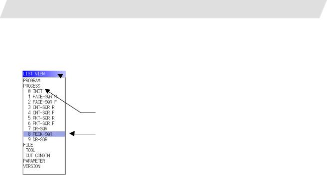
(2)Objects
The list of objects that can be selected are displayed. The object is composed of the main object and the sub object that the main object is detailed. The details of each object are as follows.
Main object |
Sub object |
Details |
PROGRAM |
- |
Newly creates, reads out, and deletes, etc. the NC program. |
PROCESS |
0 INIT |
Displays the currently edited process list. |
|
1 DR-LINE |
The settings of the selected process can be displayed and |
|
: |
changed. |
FILE |
TOOL |
Displays and changes the tool file. |
|
CUT CONDTN |
Displays and changes the cutting conditions for each process |
|
|
per workpiece material. |
PARAMETER |
- |
Displays the tool option and the miscellaneous parameter to |
|
|
be used in each process. Those can be changed. |
VERSION |
- |
Displays the version data of the NAVI MILL. |
(Note) If too many processes are registered and all the objects cannot be displayed, a scroll bar will be displayed. In this case, change display of the list by pressing cursor key or page key down, or by clicking on the scroll bar.
- 8 -

2. FUNCTIONS OF DISPLAY AREA
2.1 LIST VIEW Area
(3) Cursors
When the LIST VIEW area is active and the object is selected with the cursor, the display in the OPERATION VIEW area and the menu display area will be changed.
<Cursor Movement>
The cursor is moved using the cursor keys or a pointing device.
Key type |
Operation of cursor |
[↑] Cursor key |
Moves the cursor one field up regardless of the main object or sub object. |
|
Note that if the ↑ cursor is pressed when the cursor is at the top, the cursor |
|
does not move. |
[↓] Cursor key |
Moves the cursor one field down regardless of the main object or sub object. |
|
Note that if the ↓ cursor is pressed when the cursor is at the bottom, the cursor |
|
does not move. |
[←] Cursor key |
When the cursor is at the sub object, moves the cursor to the previous main |
|
object. |
[→] Cursor key |
When the cursor is at the sub object, moves the cursor to the next main object. |
|
|
[Page Up] key |
Moves the displayed data toward the top. |
|
|
[Page Down] |
Moves the displayed data toward the bottom. |
key |
|
Pointing device |
Cursor jumps to the spot where clicked with a pointing device. If an object not |
|
selectable is clicked, cursor does not jump. |
- 9 -

2. FUNCTIONS OF DISPLAY AREA
2.2 OPERATION VIEW Area
2.2 OPERATION VIEW Area
The various data are displayed in this area. Selecting the object in the LIST VIEW area changes the contents displayed in the OPERATION VIEW area.
 (1) Area bar
 (2) Help
 (3) Guide drawing
(4) Sub cursor
(1)Area bar
When the OPERATION VIEW area is active, the area bar is highlighted. The name of the currently edited program is displayed.
(2)Help
Quick reference on the setting items is displayed.
(3)Guide drawing
When the process is edited, a guide drawing according to the currently edited machining mode is displayed.
(4)Sub cursor
Key type |
Operation of cursor |
[↑] Cursor key |
Moves the cursor one field up. |
|
Note that if the ↑ cursor is pressed when the cursor is at the top, the cursor |
|
does not move. |
[↓] Cursor key |
Moves the cursor one field down. |
|
Note that if the ↓ cursor is pressed when the cursor is at the bottom, the cursor |
|
does not move. |
[Page Up] key |
Moves the displayed data toward the top. |
[Page Down] |
Moves the displayed data toward the bottom. |
key |
|
- 10 -

2. FUNCTIONS OF DISPLAY AREA
2.3 Setting Area
2.3 Setting Area
The value to be set to data is input.
2.4 Message Area
An error message or operation message, etc. during operation is displayed.
2.5 Menu Display Area
The screen operation is selected, and the screen is changed.
The different menus are displayed in each screen. (Refer to the chapter 4.)
- 11 -

3. BASIC OPERATIONS
3.1 Changing Active View
3. BASIC OPERATIONS
3.1 Changing Active View
To operate NAVI MILL, activate either LIST VIEW area or OPERATION VIEW area. When the VIEW is active, the area bar is highlighted and data can be input. Use menu keys [←] and [→] or a pointing device to change one of the VIEWs to be activated.
3.2 Changing Screen
When the object is selected in the LIST VIEW area, the screen (contents in the OPERATION VIEW area) changes. (Refer to the section 2.1 LIST VIEW Area.)
Note that the screen cannot be changed while the OPERATION VIEW area is active.
In such a case, press the [←] menu key or click "LIST VIEW" with a pointing device to turn the LIST VIEW area active.
Operation example
(1) Open the program edit screen.
The OPERATION VIEW area is active.
(2) Press the [←] menu key.
The LIST VIEW area will turn active.
- 12 -
3.BASIC OPERATIONS
(3)Select the object with the cursor key.
(4) Press the [MODIFY] menu key.
3.2 Changing Screen
The OPERATION VIEW area will change into the screen corresponding to the selected object.
The OPERATION VIEW area will turn active.
- 13 -

3. BASIC OPERATIONS
3.3 Setting Data
3.3 Setting Data
After moving the sub cursor, input the data into the setting area and then press the [INPUT] key, and the data will be set. (The sub cursor is displayed only when the OPERATION VIEW area is active.)
Sub-cursor
 Setting area
- 14 -

3. BASIC OPERATIONS
3.3 Setting Data
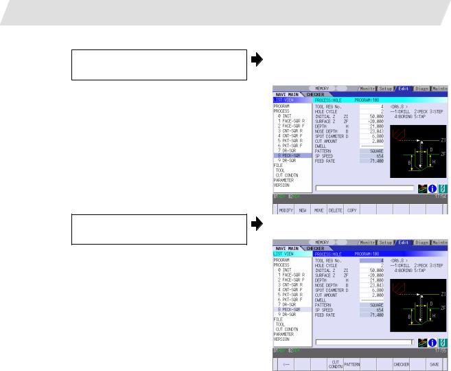
Operation method
An example for setting the data on the hole drilling screen is shown below.
(1) Screen selection
Select the object to be changed from the LIST VIEW and press [MODIFY] menu key.
(2) Setting item selection
Move the sub cursor with cursor keys.
The OPERATION VIEW area will turn active.
(Refer to the section 3.2 "Changing screen".)
This is an example of the sub cursor movement on the hole drilling screen.
(3) Data key input |
|
|
|
|
|
Set data with the numeral keys or |
|
The data is set in the data setting area. |
|
|
alphabet keys, etc. |
|
18 000 |
|
[1][2] [3] [.] [4] [5] [6]
(4)[Input] key input
Press the [input] key. |
Data for the selected setting item is set. |
The sub cursor moves to the next position.
(Note 1) The contents in the data setting area are only displayed when [INPUT] key is not pressed and will be invalidated if the screen is changed at this time. Data for the currently selected setting item will be set when [INPUT] key is pressed.
(Note 2) If illegal data is set, an error occurs when [Input] is pressed. Set the correct data again.
- 15 -

3. BASIC OPERATIONS
3.3 Setting Data
Operations in the data setting area
The key is input at the position where the cursor is displayed. If a cursor is not displayed, the key input is invalid.
When a key is input, the data appears at the cursor position, and the cursor moves one character space to the right.

 [→] / [←] keys: Moves the cursor one character to the left or right.
(1) The cursor is at the position shown on |
|
the right. |
1 2 3 7 7 7 | 4 5 6 |
(2) Press the [→] key.
The cursor moves one character space to the right.
1 2 3 7 7 7 4 | 5 6

 [DETETE] key: Deletes the character in front of the cursor.
(1) |
Move the cursor to the |
position where |
|
The cursor moves in the data setting area. |
||
|
the data is to be deleted. |
|
|
1 2 3 4 |
| 5 6 |
|
(2) |
|
|
The character in front of the cursor is |
|||
|
||||||
Press the [DETETE] key. |
|
|||||
|
|
|
|
deleted. |
|
|
|
|
|
|
1 2 3 |
| 5 6 |
|
|
|
|
|
|
|
|
- 16 -
 Loading...