


SMV
Frequency Inverter |
Operating instructions EN |
|
(13465100)

Copyright © 2013 - 2006 Lenze AC Tech Corporation
All rights reserved. No part of this manual may be reproduced or transmitted in any form without written permission from Lenze AC Tech Corporation. The information and technical data in this manual are subject to change without notice. Lenze AC Tech Corporation makes no warranty of any kind with respect to this material, including, but not limited to, the implied warranties of it’s merchantability and fitness for a given purpose. Lenze AC Tech Corporation assumes no responsibility for any errors that may appear in this manual.
All information given in this documentation has been carefully selected and tested for compliance with the hardware and software described. Nevertheless, discrepancies cannot be ruled out. We do not accept any responsibility nor liability for damages that may occur. Any necessary corrections will be implemented in subsequent editions.
This document printed in the United States

About theseInstructions |
Contents |
2 |
|||
|
|||||
1 |
Safety Information.................................................................................................... |
|
3 |
||
2 |
Technical Data........................................................................................................... |
|
7 |
||
|
2.1 |
Standards and Application Conditions.................................................................................... |
7 |
||
|
2.2 |
SMV Type Number Designation............................................................................................. |
8 |
||
|
2.3 |
Ratings |
................................................................................................................................... |
|
9 |
3 |
Installation............................................................................................................... |
|
|
12 |
|
|
3.1 |
Dimensions ....................................................................................................and Mounting |
12 |
||
|
|
3.1.1 ............................................................... |
NEMA 1 (IP31) Models < 30HP (22kW) |
12 |
|
|
|
3.1.2 ............................................................... |
NEMA 1 (IP31) Models > 30HP (22kW) |
13 |
|
|
|
3.1.3 ...................................................................................... |
NEMA 4X (IP65) Models |
14 |
|
|
|
3.1.4 ................................................. |
NEMA 4X (IP65) Models with Disconnect Switch |
15 |
|
|
3.2 |
Electrical .............................................................................................................Installation |
16 |
||
|
|
3.2.1 .............................................................................................. |
Power Connections |
16 |
|
|
|
............................ |
3.2.1.1 Mains Connection to 120VAC Single - Phase Supply |
16 |
|
|
|
............................ |
3.2.1.2 Mains Connection to 240VAC Single - Phase Supply |
17 |
|
|
|
........................................... |
3.2.1.3 Mains Connection to Three - Phase Supply |
17 |
|
|
|
................................................................................. |
3.2.1.4 |
Motor Connection |
17 |
|
|
........................... |
3.2.1.5 Installation Recommendations for EMC Compliance |
18 |
|
|
|
................................................. |
3.2.1.6 NEMA 4X (IP65) Input Terminal Block |
18 |
|
|
|
................................................................ |
3.2.1.7 |
Dynamic Brake Connections |
19 |
|
|
3.2.2 ................................................................................ |
Fuses/Cable Cross - Sections |
20 |
|
|
|
3.2.3 ................................................................................................. |
Control Terminals |
21 |
|
4 |
Commissioning....................................................................................................... |
|
23 |
||
|
4.1 |
Local Keypad ........................................................................................................& Display |
23 |
||
|
4.2 |
Drive Display .................................................................................and Modes of Operation |
25 |
||
|
4.3 |
Parameter .................................................................................................................Setting |
|
26 |
|
|
4.4 |
Electronic ...............................................................................Programming Module (EPM) |
26 |
||
|
4.5 |
Parameter ...................................................................................................................Menu |
|
27 |
|
|
|
4.5.1 ....................................................................................... |
Basic Setup Parameters |
27 |
|
|
|
4.5.2 ........................................................................................... |
I/O Setup Parameters |
31 |
|
|
|
4.5.3 ............................................................................... |
Advanced Setup Parameters |
35 |
|
|
|
4.5.4 .................................................................................................... |
PID Parameters |
39 |
|
|
|
4.5.5 ................................................................................................ |
Vector Parameters |
41 |
|
|
|
4.5.6 ............................................................................................. |
Network Parameters |
43 |
|
|
|
4.5.7 ......................................................................................... |
Diagnostic Parameters |
44 |
|
|
|
....................................................... |
4.5.7.1 Terminal & Protection Status Display |
45 |
|
|
|
............................................................................. |
4.5.7.2 Keypad Status Display |
45 |
|
|
|
4.5.8 ............................... |
Onboard Communications Parameters 15 - 60HP (11 - 45kW) |
46 |
|
|
|
4.5.9 ........................................................................................ |
Sequencer Parameters |
47 |
|
|
|
.............................................................. |
4.5.9.1 Sequencer Flow Diagram Left |
55 |
|
|
|
........................................................... |
4.5.9.2 Sequencer Flow Diagram Right |
56 |
|
|
|
................................................................................. |
4.5.9.3 |
Sequencer Status |
57 |
5 |
Troubleshooting .........................................................................and Diagnostics |
58 |
|||
|
5.1 |
Status/Warning ....................................................................................................Messages |
58 |
||
|
5.2 |
Drive Configuration .............................................................................................Messages |
59 |
||
|
5.3 |
Fault Messages.................................................................................................................... |
|
59 |
|
Appendix A |
......................................................................................................................... |
|
|
62 |
|
|
A.1 |
Permissable ..................................................................................................Cable Lengths |
62 |
||
Lenze SMVector 13465100 EDBSV01 EN v18 |
1 |
About These Instructions
This documentation applies to the SMV frequency inverter and contains important technical data regarding the installation, operation, and commissioning of the inverter.
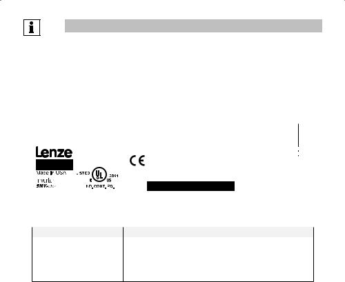
These instructions are only valid for SMV frequency inverters with software revision 4.23 or higher for version 4.23 software, the drive nameplate illustrated below would show “42” in the “F” location.
Please read these instructions in their entirety before commissioning the drive.
|
|
|
|
|
|
|
|
|
|
|
|
|
|
|
|
|
|
|
|
|
|
|
|
|
|
|
|
|
|
|
|
|
|
|
|
|
|
|
A |
|
B |
|
|
|
|
C |
|
|
|
|
|
D |
|
|
|
|
|
E |
F |
||||||
|
|
|
|
|
|
|
|
|
|
|
|
|
|
|
|
|
|
|
|
|
|
|
|
|
|
|
|
|
|
|
|
|
|
|
|
|
|
|
Type: |
|
|
|
INPUT: |
3~ |
(3/PE) |
OUTPUT: |
3~ |
|
(3/PE) |
For detailed information |
|
|
|||||||||||||
|
|
|
|
|
|
ESV751N04TXB |
|
|
400/480 V |
|
0 - 400/460 V |
|
refer to instruction |
|
|
|||||||||||||||||
|
|
|
|
|
|
Id-No: 00000000 |
|
|
2.9/2.5 A |
|
|
2.4/2.1 A |
|
Manual: |
SV01 |
|
|
|
||||||||||||||
|
|
|
|
|
|
|
|
|
|
|
|
|
|
|
|
|
|
|
|
|
||||||||||||
|
|
|
|
|
|
|
|
|
|
|
|
50-60 HZ |
|
0.75 KW/1HP |
|
000000000000000000 |
|
|
|
|
|
|||||||||||
|
|
|
|
|
|
|
|
|
|
|
|
|
|
|
|
|
|
0 - 500 HZ |
ESV751N04TXB000XX## |
|
|
|
## |
|
||||||||
|
|
|
|
|
|
|
|
|
|
|
TYPE-4X INDOOR USE ONLY |
|
|
|
||||||||||||||||||
|
|
|
|
|
|
|
|
|
|
|
|
|
|
|||||||||||||||||||
|
|
|
|
|
|
|
|
|
|
|
|
|
|
|
|
|
|
|
|
|
|
|
|
|
|
|
|
|
|
|
|
|
|
|
|
|
|
|
|
|
|
|
|
|
|
|
|
|
|
|
|
|
|
|
|
|
|
|
|
|
|
|
|
|
|
|
|
|
|
|
|
|
|
|
|
|
|
|
|
|
|
|
||||||||||||||||
|
A |
|
B |
|
|
|
C |
|
D |
|
|
|
E |
|
|
F |
||||||||||||||||
|
|
|
|
|
|
|
|
|
|
|
|
|
|
|
||||||||||||||||||
|
Certifications |
|
|
Type |
|
|
|
Input Ratings |
|
Output Ratings |
|
|
Hardware Version |
|
Software Version |
|||||||||||||||||
|
|
|
|
|
|
|
|
|
|
|
|
|
|
|
|
|
|
|
|
|
|
|
|
|
|
|
||||||
|
|
|
|
|
|
|
|
|
|
|
|
|
|
|
|
|
|
|
|
|
|
|
|
|
||||||||
|
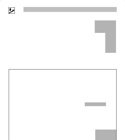
Scope of delivery |
|
|
|
|
|
Important |
|
|
|
|
|
|
|
|
|
|
|
|
|
|
|
|
|
||||||||
|
|
|
|
|
|
|
|
|||||||||||||||||||||||||
|
• 1 SMV Inverter |
|
|
|
|
|
After receipt of the delivery, check immediately whether the items delivered match |
|||||||||||||||||||||||||
|
|
with EPM installed (see Section 4.4) the accompanying papers. Lenze AC Tech does not accept any liability for deficiencies |
||||||||||||||||||||||||||||||
|
• 1 Operating Instructions manual |
|
|
|
claimed subsequently. |
|
|
|
|
|
|
|
|
|
|
|
|
|
|
|
|
|
||||||||||
|
|
|
|
|
|
|
|
|
|
|
Claim: |
|
|
|
|
|
|
|
|
|
|
|
|
|
|
|
|
|
||||
•visible transport damage immediately to the forwarder.
•visible deficiencies /incompleteness immediately to your Lenze AC Tech representative
Related Documents
The documentation listed herein contains information relevant to the operation of the SMVector frequency inverter. To obtain the latest documentation, visit the Technical Library at http://www.lenzeamericas.com.
Document # |
Description |
CMVINS01 |
SMVector Communications Module Installation Instruction |
CMVMB401 |
SMVector ModBus RTU over RS485 Communications Reference Guide |
CMVLC401 |
SMVector Lecom Communications Reference Guide |
CMVCAN01 |
SMVector CANopen Communications Reference Guide |
CMVDVN01 |
SMVector DeviceNet Communications Reference Guide |
CMVETH01 |
SMVector EtherNet/IP Communications Reference Guide |
CMVPFB01 |
SMVector PROFIBUS Communications Reference Guide |
ALSV01 |
SMVector Additional I/O Module Installation and Operation Manual |
DBV01 |
SMVector Dynamic Braking |
PTV01 |
SMVector Potentiometer Install Instructions |
RKV01 |
SMVector ESVZXK1 Remote Keypad |
RKVU01 |
SMVector ESVZXH0 Remote Keypad (for NEMA 1 15-60HP (11-45kW) Drives) |
2 |
Lenze SMVector 13465100 EDBSV01 EN v18 |

Safety Information
1Safety Information
General
Some parts of Lenze AC Tech controllers can be electrically live and some surfaces can be hot. Nonauthorized removal of the required cover, inappropriate use, and incorrect installation or operation creates the risk of severe injury to personnel and/or damage to equipment.
All operations concerning transport, installation, and commissioning as well as maintenance must be carried out by qualified, skilled personnel who are familiar with the installation, assembly, commissioning, and operation of variable frequency drives and the application for which it is being used.
Installation
Ensure proper handling and avoid excessive mechanical stress. Do not bend any components and do not change any insulation distances during transport, handling, installation or maintenance. Do not touch any electronic components or contacts. This drive contains electrostatically sensitive components, which can easily be damaged by inappropriate handling. Static control precautions must be adhered to during installation, testing, servicing and repairing of this drive and associated options. Component damage may result if proper procedures are not followed.
To ensure proper operation, do not install the drive where it is subjected to adverse environmental conditions such as combustible, oily, or hazardous vapors; corrosive chemicals; excessive dust, moisture or vibration; direct sunlight or extreme temperatures.
This drive has been tested by Underwriters Laboratory (UL) and is UL Listed in compliance with the UL508C Safety Standard. This drive must be installed and configured in accordance with both national and international standards. Local codes and regulations take precedence over recommendations provided in this and other Lenze AC Tech documentation.
The SMVector drive is considered a component for integration into a machine or process. It is neither a machine nor a device ready for use in accordance with European directives (reference machinery directive and electromagnetic compatibility directive). It is the responsibility of the end user to ensure that the machine meets the applicable standards.
Electrical Connection
When working on live drive controllers, applicable national safety regulations must be observed. The electrical installation must be carried out according to the appropriate regulations (e.g. cable cross-sections, fuses, protective earth [PE] connection). While this document does make recommendations in regards to these items, national and local codes must be adhered to.
The documentation contains information about installation in compliance with EMC (shielding, grounding, filters and cables). These notes must also be observed for CE-marked controllers. The manufacturer of the system or machine is responsible for compliance with the required limit values demanded by EMC legislation.
Application
The drive must not be used as a safety device for machines where there is a risk of personal injury or material damage. Emergency Stops, over-speed protection, acceleration and deceleration limits, etc must be made by other devices to ensure operation under all conditions.
The drive does feature many protection devices that work to protect the drive and the driven equipment by generating a fault and shutting the drive and motor down. Mains power variances can also result in shutdown of the drive. When the fault condition disappears or is cleared, the drive can be configured to automatically restart, it is the responsibility of the user, OEM and/or integrator to ensure that the drive is configured for safe operation.
Lenze SMVector 13465100 EDBSV01 EN v18 |
3 |
Safety Information
Explosion Proof Applications
Explosion proof motors that are not rated for inverter use lose their certification when used for variable speed. Due to the many areas of liability that may be encountered when dealing with these applications, the following statement of policy applies:
Lenze AC Tech Corporation inverter products are sold with no warranty of fitness for a particular purpose or warranty of suitability for use with explosion proof motors. Lenze AC Tech Corporation accepts no responsibility for any direct, incidental or consequential loss, cost or damage that may arise through the use of AC inverter products in these applications. The purchaser expressly agrees to assume all risk of any loss, cost or damage that may arise from such application.
Operation
Systems including controllers must be equipped with additional monitoring and protection devices according to the corresponding standards (e.g. technical equipment, regulations for prevention of accidents, etc.). The controller may be adapted to your application as described in this documentation.
DANGER!
•After the controller has been disconnected from the supply voltage, live components and power connection must not be touched immediately, since capacitors could be charged. Please observe the corresponding notes on the controller.
•Close all protective covers and doors prior to and during operation.
•Do not cycle input power to the controller more than once every two minutes.
•For SMVector models that are equipped with a Disconnect Switch (11th character in model number is L or M), the Disconnect Switch is intended as a motor service disconnect and does not provide branch circuit protection to the inverter or motor. When servicing the motor, it is necessary to wait 3 minutes after turning this switch to the off position before working on motor power wiring as the inverter stores electrical power. To service the inverter, it is necessary to remove mains ahead of the drive and wait 3 minutes.
Safety Notifications
All safety information given in these Operating Instructions includes a visual icon, a bold signal word and a description.
Signal Word! (characterizes the severity of the danger)
NOTE (describes the danger and informs on how to proceed)
|
|
Icon |
Signal Word |
Meaning |
Consequences if ignored |
|
|
|
|
|
|
|
|
|
|
|
|
|
|
DANGER! |
Warns of hazardous electrical voltage. |
Death or severe injuries. |
|
|
|
|
|
|
|
|
|
|
|
|
|
WARNING! |
Warns of potential, very hazardous |
Risk of severe injury to personnel and/or |
|
|
|
|
|
|
situations. |
damage to equipment. |
|
|
|
|
|
|
|
|
|
|
|
|
|
WARNING! |
Warns of hot surface and risk of burns. |
Risk of severe injury to personnel. |
|
|
|
|
|
Hot Surface |
Labels may be on or inside the |
|
|
|
|
|
|
|
equipment to alert people that surfaces |
|
|
|
|
|
|
|
may reach dangerous temperatures. |
|
|
|
|
|
|
|
|
|
|
|
|
|
|
STOP! |
Warns of potential damage to material |
Damage to the controller/drive or its |
|
|
|
|
|
|
and equipment. |
environment. |
|
|
|
|
|
|
|
|
|
|
|
|
|
NOTE |
Designates a general, useful note. |
None. If observed, then using the control- |
|
|
|
|
|
|
|||
|
|
|
|
|
|
ler/drive system is made easier. |
|
|
|
|
|
|
|
|
|
|
|
|
|
|
|
|
|
4 |
|
|
|
|
Lenze SMVector 13465100 EDBSV01 EN v18 |
||
Safety Information
Harmonics Notification in accordance with EN 61000-3-2, EN 61000-3-12:
Operation in public supply networks (Limitation of harmonic currents i.a.w. EN 61000-3-2, Electromagnetic Compatibility (EMC) Limits). Limits for harmonic current emissions (equipment input current up to 16A/phase).
Directive |
Total Power |
Additional Measures Required for Compliance (2) |
|
connected to Mains |
|
|
(public supply) |
|
|
|
|
|
< 0.5kW |
with mains choke |
EN 61000-3-2 |
|
|
0.5 ... 1kW |
with active filter |
|
|
|
|
|
> 1kW |
complies without additional measures |
|
|
|
EN 61000-3-12 |
16 ... 75amp |
Additional measures are required for compliance with the standard |
|
|
|
(1)For compliance with EMC regulations, the permissable cable lengths may change.
(2)The additional measures described only ensure that the controller meets the requirements of the EN 61000-3-2. The machine/system manufacturer is responsible for the machine’s compliance with the regulations.
Safety Information in accordance with EN 61800-5-1:
DANGER! - Risk of Electric Shock
Capacitors retain charge for approximately 180 seconds after power is removed. Disconnect incoming power and wait at least 3 minutes before touching the drive.
DANGER! - Risque de choc électrique
Les condensateurs restent sous charge pendant environ 180 secondes après une coupure de courant. Couper l’alimentation et patienter pendant au moins 3 minutes avant de toucher l’entraînement.
WARNING!
• This product can cause a d.c. current in the PE conductor. Where a residual currentoperated (RCD) or monitoring (RCM) device is used for protection in case of direct or indirect contact, only an RCD or RCM Type B is allowed on the supply side of this product.
•Leakage Current may exceed 3.5mA AC. The minimum size of the PE conductor shall comply with local safety regulations for high leakage current equipment.
•In a domestic environment, this product may cause radio interference in which case supplementary mitigation measures may be required.
Lenze SMVector 13465100 EDBSV01 EN v18 |
5 |
Safety Information
Safety Information in accordance with UL:
Note for UL approved system with integrated controllers: UL warnings are notes which apply to UL systems. The documentation contains special information about UL.
• Integral solid state protection does not provide branch circuit protection. Branch circuit protection must be provided in accordance with the National Electrical Code and any additional local codes. The
Warnings! |
use of fuses or circuit breakers is the only approved means for branch circuit protection. |
|
•When protected by CC and T Class Fuses, suitable for use on a circuit capable of delivering not more than 200,000 rms symmetrical amperes, at the maximum voltage rating marked on the drive.
•Additionally suitable when protected by a circuit breaker having an interrupting rating not less than 200,000 rms symmetrical amperes, at the maximum voltage rating marked on the drive. (Excludes ESV113xx2T, ESV153xx2T, ESV113xx4T, ESV153xx4T, ESV183xx4T, ESV223xx4T, ESV303xx4T, ESV113xx6T, ESV153xx6T, ESV183xx6T, ESV223xx6T, and ESV303xx6T).
•Use minimum 75°C copper wire only, except for control circuits.
•For control circuits, use wiring suitable for NEC Class 1 circuits only.
•Torque Requirements (in accordance with UL) are listed in section 3 . 2 . 1, Power Connections and in 3.2.3, Control terminals
•Shall be installed in a pollution degree 2 macro-environment.
•NEMA 1 (IP31) models shall be installed in a pollution degree 2 macro-environment.
•All models are suitable for installation in a compartment handling Conditioned Air (i.e., plenum rated).
WARNING!
The opening of branch-circuit protective device may be an indication that a fault has been interrupted. To reduce the risk of fire or electric shock, current carrying parts and other components of the controller should be examined and replaced if damaged.
AVERTISSEMENT!
Le déclenchement du dispositif de protection du circuit de dérivation peut être dû à une coupure qui résulte d’un courant de défaut. Pour limiter le risque d’incendie ou de choc électrique, examiner les pièces porteuses de courant et les autres éléments du contrôleur et les remplacer s’ils sont endommagés. En cas de grillage de l’élément traverse par le courant dans un relais de surcharge, le relais tout entier doit être remplacé.
NOTE
Control and communications terminals provide reinforced insulation (i.e. considered SELV or PELV, providing protection in case of direct contact) when the drive is connected to a power system rated up to 300VAC between phase to ground (PE) and the applied voltage on Terminals 16 and 17 is less than 150VAC between phase to ground. Otherwise, control and communications terminals provide basic insulation.
6 |
Lenze SMVector 13465100 EDBSV01 EN v18 |

Technical Data
2Technical Data
2.1Standards and Application Conditions
Conformity |
CE |
Low Voltage (2006/95/EC) & EMC (2004/108/EC) Directives |
|
|
|
|
|
Approvals |
UL508C |
Underwriters Laboratories -Power Conversion Equipment |
|
|
|
|
|
Input voltage phase imbalance |
< 2% |
|
|
|
|
|
|
|
|
−− For central grounded systems, operation is permitted |
|
|
TT |
without restrictions. |
|
Supported Power Systems |
−− For corner grounded 400/500V systems, operation is |
||
TN |
|||
|
possible but reinforced insulation to control circuits is |
||
|
|
||
|
|
compromised. |
|
|
|
|
|
Humidity |
< 95% non-condensing |
||
|
|
|
|
|
Transport |
-25 … +70°C |
|
Temperature range |
|
|
|
Storage |
-20 … +70°C |
||
|
|
|
|
|
Operation |
-10 … +55°C (with 2.5%/°C current derating above +40°C) |
|
|
|
|
|
Installation height |
0 - 4000m a.m.s.l. |
(with 5%/1000 m current derating above 1000m a.m.s.l.) |
|
|
|
|
|
Vibration resistance |
acceleration resistant up to 1.0g |
||
|
|
|
|
Earth leakage current |
> 3.5 mA to PE |
|
|
|
|
|
|
Max Permissable Cable Length (1) |
<= 4.0 Hp (3.0 kW) |
30 meters shielded, 60 meters un-shielded |
|
|
|
||
=> 5.0 Hp (3.7 kW) |
50 meters shielded, 100 meters un-shielded. |
||
|
|||
|
|
|
|
|
IP31/NEMA 1 |
IP65/NEMA 4X |
|
Enclosure |
|
|
|
NEMA 1 and NEMA 4X model enclosures are plenum rated in accordance with UL |
|||
|
|||
|
508C and are suitable for installation in a compartment handling conditioned air. |
||
Protection measures against |
Earth fault, phase loss, over voltage, under voltage, motor stalling, over temperature |
||
motor overload (125% of FLA), short circuit (SCCR=200kA at rated voltage) |
|||
|
|||
|
< 0.5kW |
with mains choke |
|
Compliance with EN 61000-3-2 |
|
|
|
0.5 ... 1kW |
with active filter |
||
Requirements (2) |
|||
|
|
||
> 1kW |
without additional measures |
||
|
|||
|
|
|
|
Compliance with EN 61000-3-12 |
16 ... 75amp |
Additional measures required for compliance with EN 61000-3-12 |
|
Requirements (2) |
|
|
|
Operation in public supply networks (Limitation of harmonic currents i.a.w. EN 61000-3-2, Electromagnetic Compatibility (EMC) Limits). Limits for harmonic current emissions (equipment input current up to 16A/phase).
(1)The stated cable lengths are permissible at default carrier frequencies (refer to parameter P166).
(2)The additional measures described only ensure that the controller meets the requirements of the EN 61000-3-2. The machine/system manufacturer is responsible for the machine’s compliance with the regulations.
Lenze SMVector 13465100 EDBSV01 EN v18 |
7 |
Technical Data
2.2SMV Type Number Designation
The table herein describes the Type numbering designation for the SMVector Inverter models.
|
|
ESV |
152 |
N0 |
2 |
T |
X |
B |
Electrical Products in the SMVector Series |
|
|
|
|
|
|
|
|
Power Rating in kW: |
|
|
|
|
|
|
|
|
251 |
= 0.25kW (0.33HP) |
113 = 11.0kW (15HP) |
|
|
|
|
|
|
371 |
= 0.37kW (0.5HP) |
153 = 15.0kW (20HP) |
|
|
|
|
|
|
751 |
= 0.75kW (1HP) |
183 = 18.5kW (25HP) |
|
|
|
|
|
|
112 |
= 1.1kW (1.5HP) |
223 = 22.0kW (30HP) |
|
|
|
|
|
|
152 |
= 1.5kW (2HP) |
303 = 30.0kW (40HP) |
|
|
|
|
|
|
222 |
= 2.2kW (3HP) |
373 = 37.5kW (50HP) |
|
|
|
|
|
|
302 |
= 3.0kW (4HP) |
453 = 45.0kW (60HP) |
|
|
|
|
|
|
402 |
= 4.0kW (5HP) |
|
|
|
|
|
|
|
552 |
= 5.5kW (7.5HP) |
|
|
|
|
|
|
|
752 |
= 7.5kW (10HP) |
|
|
|
|
|
|
|
Installed I/O & Communication Module(s): |
|
|
|
|
|
|
|
|
C_ = CANopen (Available all models) |
The “_” blank can be: |
|
|
|
|
|
||
D_ = DeviceNet (Available all models) |
0 = Standard Keypad |
|
|
|
|
|
||
E_ = Ethernet/IP, (Available all models) |
|
|
|
|
|
|
|
|
R_ = RS-485 / ModBus /Lecom (Avail all models) |
|
|
|
|
|
|
|
|
P_ = ProfiBus-DP (Available all models) |
|
|
|
|
|
|
|
|
N_ = No Communications installed |
|
|
|
|
|
|
|
|
Input Voltage: |
|
|
|
|
|
|
|
|
1 = 120 VAC (doubler output) or 240 VAC |
|
|
|
|
|
|
|
|
2 = 240 VAC |
|
|
|
|
|
|
|
|
4 = 400/480 VAC |
|
|
|
|
|
|
|
|
6 = 600 VAC |
|
|
|
|
|
|
|
|
Input Phase: |
|
|
|
|
|
|
|
|
S = Single Phase Input only |
|
|
|
|
|
|
|
|
Y = Single or Three Phase Input |
|
|
|
|
|
|
|
|
T = Three Phase Input only |
|
|
|
|
|
|
|
|
Input Line Filter |
|
|
|
|
|
|
|
|
F = Integral EMC Filter
L = Integral EMC Filter and Integrated Disconnect Switch (NEMA 4X/IP65 Models only)
M = Integrated Disconnect Switch (NEMA 4X/IP65 Models only)
X = No EMC Filter/ No Disconnect Switch
Enclosure:
B = NEMA 1/IP31; Indoor only
C = NEMA 4X/IP65; Indoor only; Convection cooled
D = NEMA 4X/IP65; Indoor only; Fan cooled
E = NEMA 4X/IP65; Indoor/Outdoor; Convection cooled
F = NEMA 4X/IP65; Indoor/Outdoor; Fan cooled
NOTE
Prior to installation make sure the enclosure is suitable for the end-use environment
Variables that influence enclosure suitability include (but are not limited to) temperature, airborne contaminates, chemical concentration, mechanical stress and duration of exposure (sunlight, wind, precipitation).
8 |
Lenze SMVector 13465100 EDBSV01 EN v18 |
Technical Data
2.3Ratings
120V / 240VAC Models
Mains = 120V Single Phase (1/N/PE) (90...132V), 240V Single Phase (2/PE) (170...264V); 48...62Hz
Type |
Power |
Mains Current |
Output Current |
Heat Loss (Watts) |
|||||
|
|
|
|
|
|
|
|
|
|
|
|
|
120V |
240V |
Cont (In) |
Max I |
N1/IP31 |
N4X/IP65 |
N4X/IP65 |
|
Hp |
kW |
A |
A |
A |
% |
|
No filter |
W/ filter |
|
|
|
|
|
|
|
|
|
|
ESV251--1S-- |
0.33 |
0.25 |
6.8 |
3.4 |
1.7 |
200 |
24 |
|
|
|
|
|
|
|
|
|
|
|
|
ESV371--1S-- |
0.5 |
0.37 |
9.2 |
4.6 |
2.4 |
200 |
32 |
32 |
|
|
|
|
|
|
|
|
|
|
|
ESV751--1S-- |
1 |
0.75 |
16.6 |
8.3 |
4.2 |
200 |
52 |
41 |
|
|
|
|
|
|
|
|
|
|
|
ESV112--1S-- |
1.5 |
1.1 |
20 |
10.0 |
6.0 |
200 |
74 |
74 |
|
|
|
|
|
|
|
|
|
|
|
NOTES:
Output Current: The Output Current Maximum (%) is a percentage of the Output Current Continuous Amps (In) rating and is adjustable in parameter P171.
240VAC Models
|
|
Mains = 240V Single Phase (2/PE) (170...264V); 48...62Hz |
|
|
|||||||||
|
|
|
|
|
|
|
|
|
|
|
|
||
|
Type |
|
Power |
Mains Current |
Output Current |
Heat Loss (Watts) |
|||||||
|
|
|
|
|
|
|
|
|
|
|
|
|
|
|
|
|
|
|
|
240V |
Cont (In) |
Max I |
N1/IP31 |
N4X/IP65 |
N4X/IP65 |
||
|
|
Hp |
|
|
kW |
A |
|
A |
% |
|
No filter |
W/ filter |
|
|
|
|
|
|
|
|
|
|
|
|
|
||
|
ESV251--2S-- |
0.33 |
|
0.25 |
3.4 |
1.7 |
200 |
20 |
|
|
|||
|
|
|
|
|
|
|
|
|
|
|
|
|
|
|
ESV371--2S-- |
0.5 |
|
|
0.37 |
5.1 |
2.4 |
200 |
|
|
30 |
||
|
|
|
|
|
|
|
|
|
|
|
|
|
|
|
ESV751--2S-- |
1 |
|
|
0.75 |
8.8 |
4.2 |
200 |
|
|
42 |
||
|
|
|
|
|
|
|
|
|
|
|
|
|
|
|
ESV112--2S-- |
1.5 |
|
|
1.1 |
12.0 |
6.0 |
200 |
|
|
63 |
||
|
|
|
|
|
|
|
|
|
|
|
|
|
|
|
ESV152--2S-- |
2 |
|
|
1.5 |
13.3 |
7.0 |
200 |
|
|
73 |
||
|
|
|
|
|
|
|
|
|
|
|
|
|
|
|
ESV222--2S-- |
3 |
|
|
2.2 |
17.1 |
9.6 |
200 |
|
|
97 |
||
|
|
|
|
|
|
|
|
|
|
|
|||
|
|
|
|||||||||||
|
240V Single Phase (2/PE) (170...264V), 240V Three Phase (3/PE) (170...264V); 48...62Hz |
||||||||||||
|
|
|
|
|
|
|
|
||||||
|
Type |
|
Power |
Mains Current |
Output Current |
Heat Loss (Watts) |
|||||||
|
|
|
|
|
|
|
|
|
|
|
|
|
|
|
|
|
|
|
|
1~ (2/PE) |
|
3~ (3/PE) |
Cont (In) |
Max I |
N1/IP31 |
N4X/IP65 |
N4X/IP65 |
|
|
Hp |
|
|
kW |
A |
|
A |
A |
% |
|
No filter |
W/ filter |
|
|
|
|
|
|
|
|
|
|
|
|
|
|
|
ESV371--2Y-- |
0.5 |
|
|
0.37 |
5.1 |
|
2.9 |
2.4 |
200 |
27 |
26 |
|
|
|
|
|
|
|
|
|
|
|
|
|
|
|
|
ESV751--2Y-- |
1 |
|
|
0.75 |
8.8 |
|
5.0 |
4.2 |
200 |
41 |
38 |
|
|
|
|
|
|
|
|
|
|
|
|
|
|
|
|
ESV112--2Y-- |
1.5 |
|
|
1.1 |
12.0 |
|
6.9 |
6.0 |
200 |
64 |
59 |
|
|
|
|
|
|
|
|
|
|
|
|
|
|
|
|
ESV152--2Y-- |
2 |
|
|
1.5 |
13.3 |
|
8.1 |
7.0 |
200 |
75 |
69 |
|
|
|
|
|
|
|
|
|
|
|
|
|
|
|
|
ESV222--2Y-- |
3 |
|
|
2.2 |
17.1 |
|
10.8 |
9.6 |
200 |
103 |
93 |
|
|
|
|
|
|
|
|
|
|
|
|
|
|
|
|
|
|
|
|
|
|
|||||||
|
|
|
|
240V Three Phase (3/PE) (170...264V); 48...62Hz |
|
|
|||||||
|
|
|
|
|
|
|
|||||||
|
Type |
|
Power |
Mains Current |
Output Current |
Heat Loss (Watts) |
|||||||
|
|
|
|
|
|
|
|
|
|
|
|
||
|
|
|
|
|
|
240V |
Cont (In) |
Max I |
N1/IP31 |
N4X/IP65 |
N4X/IP65 |
||
|
|
Hp |
|
|
kW |
A |
|
A |
% |
|
No filter |
W/ filter |
|
|
|
|
|
|
|
|
|
|
|
|
|||
Lenze SMVector 13465100 EDBSV01 EN v18 |
|
|
|
|
|
9 |
|||||||
Technical Data
--ESV112 |
--2T |
1.5 |
1.1 |
6.9 |
6 |
200 |
64 |
|
|
|
|
|
|
|
|
|
|
|
|
ESV152-- |
2T-- |
2 |
1.5 |
8.1 |
7 |
200 |
75 |
|
|
|
|
|
|
|
|
|
|
|
|
ESV222-- |
2T-- |
3 |
2.2 |
10.8 |
9.6 |
200 |
103 |
|
|
|
|
|
|
|
|
|
|
|
|
ESV402-- |
2T-- |
5 |
4.0 |
18.6 |
16.5 |
200 |
154 |
139 |
|
|
|
|
|
|
|
|
|
|
|
ESV552-- |
2T-- |
7.5 |
5.5 |
26 |
23 |
200 |
225 |
167 |
|
|
|
|
|
|
|
|
|
|
|
ESV752-- |
2T-- |
10 |
7.5 |
33 |
29 |
200 |
274 |
242 |
|
|
|
|
|
|
|
|
|
|
|
ESV113-- |
2T-- |
15 |
11 |
48 |
42 |
180 |
485 |
468 |
|
|
|
|
|
|
|
|
|
|
|
ESV153-- |
2T-- |
20 |
15 |
59 |
54 |
180 |
614 |
591 |
|
|
|
|
|
|
|
|
|
|
|
NOTES:
Output Current: The Output Current Maximum (%) is a percentage of the Output Current Continuous Amps (In) rating and is adjustable in parameter P171.
400...480VAC Models
400 ... 480V Three Phase (3/PE) (400V: 340...440V), (480V: 340...528V); 48...62Hz
Type |
|
Power |
Mains Current |
Output Current |
Heat Loss (Watts) |
||||||||||
|
|
|
|
|
|
|
|
|
|
|
|
|
|
||
|
|
|
|
|
400V |
480V |
Cont (In) |
Max I |
N1/IP31 |
N4X/IP65 |
N4X/IP65 |
||||
|
|
Hp |
|
kW |
A |
A |
|
A |
|
% |
|
No filter |
W/ filter |
||
|
|
|
|
|
|
|
|
|
|
|
|
|
|
|
|
|
|
|
|
|
|
|
400V |
|
480V |
400V |
|
480V |
|
|
|
|
|
|
|
|
|
|
|
|
|
|
|
|
|
|
|
ESV371-- |
4T-- |
0.5 |
|
0.37 |
1.7 |
1.5 |
1.3 |
|
1.1 |
175 |
|
200 |
23 |
21 |
25 |
|
|
|
|
|
|
|
|
|
|
|
|
|
|
|
|
ESV751-- |
4T-- |
1 |
|
0.75 |
2.9 |
2.5 |
2.4 |
|
2.1 |
175 |
|
200 |
37 |
33 |
37 |
|
|
|
|
|
|
|
|
|
|
|
|
|
|
|
|
ESV112-- |
4T-- |
1.5 |
|
1.1 |
4.2 |
3.6 |
3.5 |
|
3.0 |
175 |
|
200 |
48 |
42 |
46 |
ESV152-- |
4T-- |
2 |
|
1.5 |
4.7 |
4.1 |
4.0 |
|
3.5 |
175 |
|
200 |
57 |
50 |
54 |
|
|
|
|
|
|
|
|
|
|
|
|
|
|
|
|
ESV222-- |
4T-- |
3 |
|
2.2 |
6.1 |
5.4 |
5.5 |
|
4.8 |
175 |
|
200 |
87 |
78 |
82 |
|
|
|
|
|
|
|
|
|
|
|
|
|
|
|
|
ESV302-- |
4T-- |
4 |
|
3.0 |
8.3 |
7.0 |
7.6 |
|
6.3 |
175 |
|
200 |
|
|
95 |
ESV402-- |
4T-- |
5 |
|
4.0 |
10.6 |
9.3 |
9.4 |
|
8.2 |
175 |
|
200 |
128 |
103 |
111 |
|
|
|
|
|
|
|
|
|
|
|
|
|
|
|
|
ESV552-- |
4T-- |
7.5 |
|
5.5 |
14.2 |
12.4 |
12.6 |
|
11.0 |
175 |
|
200 |
178 |
157 |
165 |
|
|
|
|
|
|
|
|
|
|
|
|
|
|
|
|
ESV752-- |
4T-- |
10 |
|
7.5 |
18.1 |
15.8 |
16.1 |
|
14.0 |
175 |
|
200 |
208 |
190 |
198 |
ESV113-- |
4T-- |
15 |
|
11 |
27 |
24 |
24 |
|
21 |
155 |
|
180 |
418 |
388 |
398 |
|
|
|
|
|
|
|
|
|
|
|
|
|
|
|
|
ESV153-- |
4T-- |
20 |
|
15 |
35 |
31 |
31 |
|
27 |
155 |
|
180 |
493 |
449 |
459 |
|
|
|
|
|
|
|
|
|
|
|
|
|
|
|
|
ESV183-- |
4T-- |
25 |
|
18.5 |
44 |
38 |
39 |
|
34 |
155 |
|
180 |
645 |
589 |
600 |
ESV223-- |
4T-- |
30 |
|
22 |
52 |
45 |
46 |
|
40 |
155 |
|
180 |
709 |
637 |
647 |
|
|
|
|
|
|
|
|
|
|
|
|
|
|
|
|
ESV303-- |
4T-- |
40 |
|
30 |
68 |
59 |
60 |
|
52 |
155 |
|
180 |
1020 |
|
|
|
|
|
|
|
|
|
|
|
|
|
|
|
|
|
|
ESV373-- |
4T-- |
50 |
|
37.5 |
85 |
74 |
75 |
|
65 |
155 |
|
180 |
1275 |
|
|
ESV453-- |
4T-- |
60 |
|
45 |
100 |
87 |
88 |
|
77 |
155 |
|
180 |
1530 |
|
|
NOTES:
Output Current: The Output Current Maximum (%) is a percentage of the Output Current Continuous Amps (In) rating and is adjustable in parameter P171.
For 400...480 VAC models, the output current maximum (%) in the 400V column is used when P107 = 0 For 400...480 VAC models, the output current maximum (%) in the 480V column is used when P107 = 1
10 |
Lenze SMVector 13465100 EDBSV01 EN v18 |
600VAC Models |
|
|
|
|
Technical Data |
|
|
|
|
|||
|
|
|
|
|
|
|
|
|||||
|
|
|
|
|
|
|
|
|
|
|
||
|
|
|
|
|
|
|
|
|
|
|
|
|
|
|
|
600V Three Phase (3/PE) (425...660V); 48...62Hz |
|
|
|
|
|||||
|
|
|
|
|
|
|
|
|
|
|
|
|
|
Type |
|
Power |
Mains Current |
Output Current |
Heat Loss (Watts) |
|
|||||
|
|
|
|
|
|
|
|
|
|
|
|
|
|
|
|
|
|
|
Cont (In) |
Max I |
N1/IP31 |
N4X/IP65 |
N4X/IP65 |
|
|
|
|
Hp |
|
kW |
A |
A |
% |
|
No filter |
W/ filter |
|
|
|
|
|
|
|
|
|
|
|
|
|
|
|
|
ESV751--6T-- |
1 |
|
0.75 |
2 |
1.7 |
200 |
37 |
31 |
|
|
|
|
|
|
|
|
|
|
|
|
|
|
|
|
|
ESV152--6T-- |
2 |
|
1.5 |
3.2 |
2.7 |
200 |
51 |
43 |
|
|
|
|
|
|
|
|
|
|
|
|
|
|
|
|
|
ESV222--6T-- |
3 |
|
2.2 |
4.4 |
3.9 |
200 |
68 |
57 |
|
|
|
|
|
|
|
|
|
|
|
|
|
|
|
|
|
ESV402--6T-- |
5 |
|
4 |
6.8 |
6.1 |
200 |
101 |
67 |
|
|
|
|
|
|
|
|
|
|
|
|
|
|
|
|
|
ESV552--6T-- |
7.5 |
|
5.5 |
10.2 |
9 |
200 |
148 |
116 |
|
|
|
|
|
|
|
|
|
|
|
|
|
|
|
|
|
ESV752--6T-- |
10 |
|
7.5 |
12.4 |
11 |
200 |
172 |
152 |
|
|
|
|
|
|
|
|
|
|
|
|
|
|
|
|
|
ESV113--6T-- |
15 |
|
11 |
19.7 |
17 |
180 |
380 |
356 |
|
|
|
|
|
|
|
|
|
|
|
|
|
|
|
|
|
ESV153--6T-- |
20 |
|
15 |
25 |
22 |
180 |
463 |
431 |
|
|
|
|
|
|
|
|
|
|
|
|
|
|
|
|
|
ESV183--6T-- |
25 |
|
18.5 |
31 |
27 |
180 |
560 |
519 |
|
|
|
|
|
|
|
|
|
|
|
|
|
|
|
|
|
ESV223--6T-- |
30 |
|
22 |
36 |
32 |
180 |
640 |
592 |
|
|
|
|
|
|
|
|
|
|
|
|
|
|
|
|
|
ESV303--6T-- |
40 |
|
30 |
47 |
41 |
180 |
930 |
|
|
|
|
|
|
|
|
|
|
|
|
|
|
|
|
|
|
ESV373--6T-- |
50 |
|
37.5 |
59 |
52 |
180 |
1163 |
|
|
|
|
|
|
|
|
|
|
|
|
|
|
|
|
|
|
ESV453--6T-- |
60 |
|
45 |
71 |
62 |
180 |
1395 |
|
|
|
|
|
|
|
|
|
|
|
|
|
|
|
|
|
NOTES:
Output Current: The Output Current Maximum (%) is a percentage of the Output Current Continuous Amps (In) rating and is adjustable in parameter P171.
STOP!
• For installations above 1000m a.m.s.l., derate In by 5% per 1000m, do not exceed 4000m a.m.s.l.
• Operation above 40°C, derate In by 2.5% per °C, do not exceed 55°C.
Output Current (In) derating for Carrier Frequency (P166) for NEMA 1 (IP31) Models: - If P166=2 (8 kHz), derate In to 92% of drive rating
- If P166=3 (10 kHz), derate In to 84% of drive rating
Output Current (In) derating for Carrier Frequency (P166) for NEMA 4X (IP65) Models:
-If P166=1 (6 kHz), derate In to 92% of drive rating
-If P166=2 (8 kHz), derate In to 84% of drive rating
-If P166=3 (10 kHz), derate In to 76% of drive rating
Lenze SMVector 13465100 EDBSV01 EN v18 |
11 |
Installation
3Installation
3.1Dimensions and Mounting
WARNING!
Drives must not be installed where subjected to adverse environmental conditions such as: combustible, oily, or hazardous vapors; corrosive chemicals; excessive dust, moisture or vibration; direct sunlight or extreme temperatures.
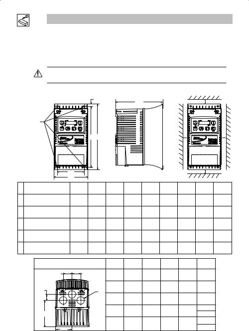
3.1.1NEMA 1 (IP31) Models < 30HP (22kW)
b2
c |
s2 |
Mounting Screws
4 x #10
18 lb-in
( 420x NmM5 )
b1 b
s1 |
s1 |
a1 |
s2 |
a |
|
|
Type |
a |
a1 |
b |
b1 |
b2 |
c |
s1 |
s2 |
m |
|
|
in (mm) |
in (mm) |
in (mm) |
in (mm) |
in (mm) |
in (mm) |
in (mm) |
in (mm) |
lb (kg) |
||
|
|
||||||||||
G1 |
ESV251~~~~~B; ESV371~~~~~B |
3.90 (99) |
3.12 (79) |
7.48 (190) |
7.00 (178) |
0.24 (6) |
4.35 (111) |
0.6 (15) |
2.0 (50) |
2.0 (0.9) |
|
ESV751~~~~~B |
|||||||||||
G2 |
ESV112~~~~~B; ESV152~~~~~B |
3.90 (99) |
3.12 (79) |
7.52 (191) |
7.00 (178) |
0.26 (7) |
5.45 (138) |
0.6 (15) |
2.0 (50) |
2.8 (1.3) |
|
ESV222~~~~~B |
|||||||||||
G3 |
ESV402~~~~~B |
3.90 (99) |
3.12 (79) |
7.52 (191) |
7.00 (178) |
0.30 (8) |
5.80 (147) |
0.6 (15) |
2.0 (50) |
3.2 (1.5) |
|
H1 |
ESV552~~~~~B; ESV752~~~~~B |
5.12 (130) |
4.25 (108) |
9.83 (250) |
9.30 (236) |
0.26 (7) |
6.30 (160) |
0.6 (15) |
2.0 (50) |
6.0 (2.0) |
|
J1 |
ESV113~~~~~B; ESV153~~~~~B |
6.92 (176) |
5.75 (146) |
12.50 (318) |
11.88 (302) |
0.31 (8) |
8.09 (205) |
0.6 (15) |
2.0 (50) |
13.55 (6.15) |
|
ESV183~~~~~B; ESV223~~~~~B |
|||||||||||
|
|
|
|
|
|
|
|
|
|
||
|
Conduit Hole Dimensions |
Type |
N |
P |
P1 |
Q |
S |
|
|||
|
in (mm) |
in (mm) |
in (mm) |
in (mm) |
in (mm) |
|
|||||
|
|
|
|
|
|
||||||
|
Q |
Q |
|
|
|
|
|
|
|
|
|
|
|
|
|
G1 |
1.84 (47) |
1.93 (49) |
.70 (18) |
1.00 (25) |
.88 (22) |
|
|
|
P1 |
|
|
G2 |
1.84 (47) |
3.03 (77) |
.70 (18) |
1.00 (25) |
.88 (22) |
|
|
|
|
S |
|
|
|
|
|
|
|
||
|
|
|
|
|
|
|
|
|
|
||
|
|
|
|
G3 |
1.84 (47) |
3.38 (86) |
.70 (18) |
1.00 (25) |
.88 (22) |
|
|
|
|
|
|
H1 |
2.46 (62) |
3.55 (90) |
.13 (3) |
1.38 (35) |
1.13 (29) |
|
|
|
P |
|
|
.88 (22) |
|
||||||
|
|
|
|
|
|
|
|
|
|||
|
|
|
|
|
|
|
|
|
|
||
|
|
|
|
J1 |
3.32 (84) |
4.62 (117) |
.73 (19) |
1.40 (36) |
1.31 (33) |
|
|
|
|
|
|
.88 (22) |
|
||||||
|
N |
|
|
|
|
|
|
|
|
||
|
|
|
|
|
|
|
|
|
|
||
12 |
|
|
|
|
Lenze SMVector 13465100 EDBSV01 EN v18 |
||||||
Installation
3.1.2NEMA 1 (IP31) Models > 30HP (22kW)
b2 |
c |
s2 |
b1 |
b |
s1 |
s1 |
|
SMV |
|
SMV |
|
a1 |
|
|
|
|
|
|
|
s2 |
|
|
a |
|
|
|
|
|
|
|
|
|
|
Type |
a |
a1 |
b |
b1 |
b2 |
c |
s1 |
s2 |
m |
|
in (mm) |
in (mm) |
in (mm) |
in (mm) |
in (mm) |
in (mm) |
in (mm) |
in (mm) |
lb (kg) |
|
|
|
|||||||||
K1 |
ESV303~~4~~B; |
8.72 (221) |
7.50 (190) |
14.19 (360) |
13.30 (338) |
0.45 (11.4) |
10.07 (256) |
0.6 (15) |
2.0 (50) |
24 (10.9) |
ESV303~~6~~B |
||||||||||
K2 |
ESV373~~4~~B; |
8.72 (221) |
7.50 (190) |
17.19 (436) |
16.30 (414) |
0.45 (11.4) |
10.07 (256) |
0.6 (15) |
2.0 (50) |
31 (14.1) |
ESV373~~6~~B |
||||||||||
K3 |
ESV453~~4~~B |
8.72 (221) |
7.50 (190) |
20.19 (513) |
19.30 (490) |
0.45 (11.4) |
10.07 (256) |
0.6 (15) |
2.0 (50) |
35 (15.9) |
ESV453~~6~~b |
||||||||||
|
Conduit Hole Dimensions |
|
Type |
N |
P |
P1 |
Q |
S |
S1 |
|
|
|
in (mm) |
in (mm) |
in (mm) |
in (mm) |
in (mm) |
in (mm) |
|||
|
|
|
|
|
||||||
|
|
S1 |
|
|
|
|
|
|
|
|
|
|
|
|
K1 |
3.75 (95) |
5.42 (137) |
1.50 (38.1) |
1.75 (44.4) |
1.75 (44.4) |
0.875 (22.2) |
|
S |
|
|
|
|
|
|
|
|
|
|
|
|
P1 |
|
|
|
|
|
|
|
|
C |
|
|
K2 |
3.75 (95) |
5.42 (137) |
1.50 (38.1) |
1.75 (44.4) |
1.75 (44.4) |
0.875 (22.2) |
|
|
|
|
|||||||
|
|
|
P |
|
|
|
|
|
|
|
|
Q |
Q |
|
K3 |
3.75 (95) |
5.42 (137) |
1.50 (38.1) |
1.75 (44.4) |
1.75 (44.4) |
0.875 (22.2) |
|
|
|
|
|
|
|
|
|
||
|
N |
N |
|
|
|
|
|
|
|
|
Lenze SMVector 13465100 EDBSV01 EN v18 |
13 |
Installation
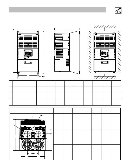
3.1.3NEMA 4X (IP65) Models
|
|
|
b2 |
|
c |
|
|
|
|
|
|
|
|
|
|
|
|
s2 |
|
|
|
|
|
|
|
|
|
|
|
|
|
|
|
Mounting Screws |
|
|
|
|
|
|
|
|
|
|
4 x #8-32 |
|
|
|
|
|
|
|
|
|
|
10 lb-in |
|
|
|
|
|
|
|
|
|
|
(1.24 x NmM4 ) |
|
|
b |
|
|
|
|
|
|
|
|
|
b1 |
|
|
s1 |
|
s1 |
|
|
|
|
|
|
|
|
|
|
|
||
|
|
|
|
|
|
|
|
s2 |
|
|
|
|
a1 |
|
|
|
|
|
|
|
|
|
|
a |
|
|
|
|
|
|
|
|
|
Type |
a |
a1 |
b |
b1 |
b2 |
c |
s1 |
s2 |
m |
|
in (mm) |
in (mm) |
in (mm) |
in (mm) |
in (mm) |
in (mm) |
in (mm) |
in (mm) |
lb (kg) |
|
|
|
|||||||||
|
ESV371N01SX_; ESV751N01SX_; |
|
|
|
|
|
|
|
|
|
|
ESV371N02YX_; ESV751N02YX_; |
|
|
|
|
|
|
|
|
|
R1 |
ESV371N04TX_; ESV751N04TX_; |
6.28 (160) |
5.90 (150) |
8.00 (203) |
6.56 (167) |
0.66 (17) |
4.47 (114) |
2.00 (51) |
2.00 (51) |
3.6 (1.63) |
ESV751N06TX_; ESV371N02SF_; |
||||||||||
|
ESV751N02SF_; ESV371N04TF_; |
|
|
|
|
|
|
|
|
|
|
ESV751N04TF_; |
|
|
|
|
|
|
|
|
|
|
ESV112N01SX_; ESV112N02YX_; |
|
|
|
|
|
|
|
|
|
|
ESV152N02YX_; ESV112N04TX_; |
|
|
|
|
|
|
|
|
|
|
ESV152N04TX_; ESV222N04TX_; |
|
|
|
|
|
|
|
|
|
R2 |
ESV152N06TX_; ESV222N06TX_; |
6.28 (160) |
5.90 (150) |
8.00 (203) |
6.56 (167) |
0.66 (17) |
6.31 (160) |
2.00 (51) |
2.00 (51) |
5.9 (2.68) |
|
ESV112N02SF_; ESV152N02SF_; |
|
|
|
|
|
|
|
|
|
|
ESV112N04TF_; ESV152N04TF_; |
|
|
|
|
|
|
|
|
|
|
ESV222N04TF_; ESV302N04TF_; |
|
|
|
|
|
|
|
|
|
S1 |
ESV222N02YX_; ESV222N02SF_ |
7.12 (181) |
6.74 (171) |
8.00 (203) |
6.56 (167) |
0.66 (17) |
6.77 (172) |
2.00 (51) |
2.00 (51) |
7.1 (3.24) |
|
ESV552N02TX~; ESV752N02TX~ |
|
|
|
|
|
|
|
|
|
T1 |
ESV752N04TX~; ESV752N06TX~; |
8.04 (204) |
7.56 (192) |
10.00 (254) |
8.04 (204) |
0.92 (23) |
8.00 (203) |
4.00 (102) |
4.00 (102) |
10.98 (4.98) |
|
ESV752N04TF~ |
|
|
|
|
|
|
|
|
|
|
ESV402N02TX_; ESV402N04TX_; |
|
|
|
|
|
|
|
|
|
V1 |
ESV552N04TX_; ESV402N06TX_ |
8.96 (228) |
8.48 (215) |
10.00 (254) |
8.04 (204) |
0.92 (23) |
8.00 (203) |
4.00 (102) |
4.00 (102) |
11.58 (5.25) |
ESV552N06TX_; ESV402N04TF_; |
||||||||||
|
ESV552N04TF_ |
|
|
|
|
|
|
|
|
|
|
ESV113N02TX~; ESV153N02TX~ |
|
|
|
|
|
|
|
|
|
|
ESV113N04TX~; ESV153N04TX~ |
|
|
|
|
|
|
|
|
|
W1 |
ESV113N04TF~; ESV153N04TF~ |
9.42 (240) |
8.94 (228) |
14.50 (368) |
12.54 (319) |
0.92 (24) |
9.45 (241) |
4.00 (102) |
4.00 (102) |
22.0 (10.0) |
ESV113N06TX~; ESV153N06TX~ |
||||||||||
|
ESV183N04TX~; ESV183N04TF~ |
|
|
|
|
|
|
|
|
|
|
ESV183N06TX~ |
|
|
|
|
|
|
|
|
|
X1 |
ESV223N04TX~; ESV223N04TF~ |
9.42 (240) |
8.94 (228) |
18.5 (470) |
16.54 (420) |
0.92 (24) |
9.45 (241) |
4.00 (102) |
4.00 (102) |
25.5 (11.6) |
ESV223N06TX~ |
_ = Last digit of part number: |
C = N4X Indoor (convection cooled) |
|
E = N4X In/Outdoor (convection cooled) |
~ = Last digit of part number: D = N4X Indoor (fan cooled)
F = N4X In/Outdoor (fan cooled)
|
Conduit Hole Dimensions |
|
Type |
N |
P |
Q |
S |
S1 |
|
|
in (mm) |
in (mm) |
in (mm) |
in (mm) |
in (mm) |
||
|
|
|
R1 |
|||||
Q |
Q |
|
3.14 (80) |
2.33 (59) |
1.50 (38) |
.88 (22) |
n/a |
|
|
Q |
Q |
|
|
|
|
|
|
|
S |
|
R2 |
3.14 (80) |
4.18 (106) |
1.50 (38) |
.88 (22) |
n/a |
|
|
S |
S1 |
3.56 (90) |
4.63 (118) |
1.50 (38) |
.88 (22) |
n/a |
|
|
|
||||||
|
|
|
T1 |
4.02 (102) |
5.00 (127) |
1.85 (47) |
1.06 (27) |
n/a |
P |
P |
S1 |
V1 |
4.48 (114) |
5.00 (127) |
1.85 (47) |
1.06 (27) |
n/a |
|
|
|||||||
|
|
|
W1 |
4.71 (120) |
5.70 (145) |
2.00 (51) |
1.375 (35) |
1.125 (28) |
N |
N |
|
|
|
|
|
|
|
|
|
X1 |
4.71 (120) |
5.70 (145) |
2.00 (51) |
1.375 (35) |
1.125 (28) |
|
|
|
|
||||||
14 |
|
|
|
Lenze SMVector 13465100 EDBSV01 EN v18 |
||||

Installation
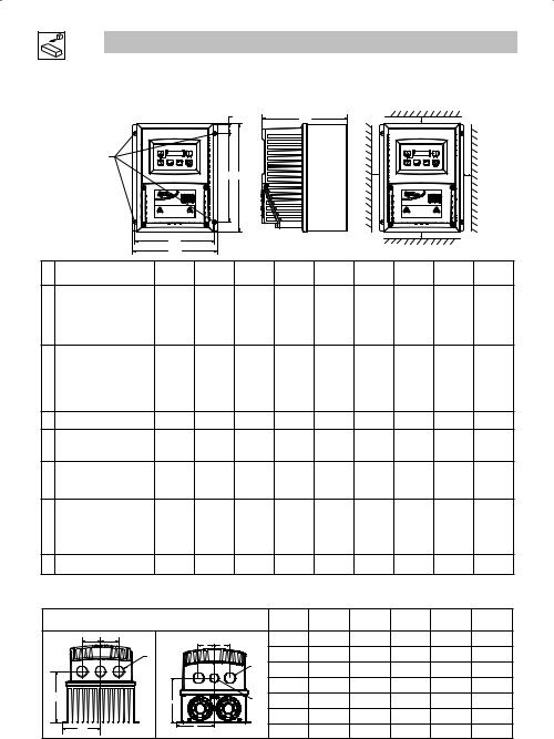
3.1.4NEMA 4X (IP65) Models with Disconnect Switch
b2 |
c1 |
|
|
c |
s2 |
Mounting Screws |
|
|
|
4 x #8-32 |
|
|
|
10 lb-in |
|
|
|
(1.24 x NmM4 ) |
b1 b |
s1 |
s1 |
a1 |
s2 |
a |
|
|
|
|
|
a |
a1 |
|
b |
b1 |
|
b2 |
|
c |
c1 |
s1 |
s2 |
m |
|
|
Type |
|
in |
in |
|
in |
in |
|
in |
|
in |
in |
in |
in |
lb |
|
|
|
|
(mm) |
(mm) |
(mm) |
(mm) |
|
(mm) |
(mm) |
(mm) |
(mm) |
(mm) |
(kg) |
||
|
ESV371N01SM_; ESV371N02YM_; |
|
|
|
|
|
|
|
|
|
|
|
|
|
||
|
ESV371N02SL_; ESV371N04TM_; |
|
|
|
|
|
|
|
|
|
|
|
|
|
||
AA1 |
ESV371N04TL_; ESV371N06TM_; |
6.28 |
5.90 |
|
10.99 |
9.54 |
|
0.66 |
|
4.47 |
.86 |
2.00 |
2.00 |
4.7 |
||
ESV751N01SM_; ESV751N02YM_; |
(160) |
(150) |
|
(279) |
(242) |
|
(17) |
|
(114) |
(22) |
(51) |
(51) |
(2.13) |
|||
|
ESV751N02SL_; ESV751N04TM_; |
|
|
|
|
|
|
|
|
|
|
|
|
|
||
|
ESV751N04TL_; ESV751N06TM_; |
|
|
|
|
|
|
|
|
|
|
|
|
|
||
|
ESV112N01SM_; ESV112N02YM_; |
|
|
|
|
|
|
|
|
|
|
|
|
|
||
|
ESV112N02SL_; ESV112N04TM_; |
|
|
|
|
|
|
|
|
|
|
|
|
|
||
|
ESV112N04TL_; ESV152N02YM_; |
6.28 |
5.90 |
|
10.99 |
9.54 |
|
0.66 |
|
6.31 |
.86 |
2.00 |
2.00 |
7.9 |
||
AA2 |
ESV152N02SL_; ESV152N04TM_; |
|
|
|
||||||||||||
(160) |
(150) |
|
(279) |
(242) |
|
(17) |
|
(160) |
(22) |
(51) |
(51) |
(3.58) |
||||
|
ESV152N04TL_; ESV152N06TM_; |
|
|
|
||||||||||||
|
|
|
|
|
|
|
|
|
|
|
|
|
|
|||
|
ESV222N04TM_; ESV222N04TL_; |
|
|
|
|
|
|
|
|
|
|
|
|
|
||
|
ESV222N06TM_; ESV302N04TL_; |
|
|
|
|
|
|
|
|
|
|
|
|
|
||
AD1 |
ESV222N02SL_; ESV222N02YM_; |
7.12 |
6.74 |
|
10.99 |
9.54 |
|
0.66 |
|
6.77 |
.86 |
2.00 |
2.00 |
9.0 |
||
(181) |
(171) |
|
(279) |
(242) |
|
(17) |
|
(172) |
(22) |
(51) |
(51) |
(4.08) |
||||
|
|
|
|
|
|
|
||||||||||
|
ESV552N02TM~; ESV752N02TM~ |
8.04 |
7.56 |
|
13.00 |
11.04 |
|
0.92 |
|
8.00 |
.86 |
4.00 |
4.00 |
13.9 |
||
AB1 |
ESV752N04TM~; ESV752N06TM~; |
|
|
|
||||||||||||
(204) |
(192) |
|
(330) |
(280) |
|
(23) |
|
(203) |
(22) |
(102) |
(102) |
(6.32) |
||||
|
ESV752N04TL~ |
|
|
|
|
|||||||||||
|
|
|
|
|
|
|
|
|
|
|
|
|
|
|
||
|
ESV402N02TM_; ESV402N04TM_; |
|
|
|
|
|
|
|
|
|
|
|
|
|
||
AC1 |
ESV552N04TM_; ESV402N06TM_; |
8.96 |
8.48 |
|
13.00 |
11.04 |
|
0.92 |
|
8.04 |
.86 |
4.00 |
4.00 |
14.7 |
||
ESV552N06TM_; ESV402N04TL_; |
(228) |
(215) |
|
(330) |
(280) |
|
(23) |
|
204) |
(22) |
(102) |
(102) |
(6.66) |
|||
|
ESV552N04TL_ |
|
|
|
|
|
|
|
|
|
|
|
|
|
|
|
AE1 |
ESV113N04TM~; ESV153N04TM~, |
9.42 |
8.94 |
|
14.50 |
12.54 |
|
0.92 |
|
9.45 |
0.73 |
4.00 |
4.00 |
23.0 |
||
ESV113N06TM~; ESV153N06TM~ |
(240) |
(228) |
|
(368) |
(319) |
|
(24) |
|
(241) |
(19) |
(102) |
(102) |
(10.4) |
|||
|
ESV113N02TM~; ESV153N02TM~ |
|
|
|
|
|
|
|
|
|
|
|
|
|
||
|
ESV113N04TL~; ESV153N04TL~ |
9.42 |
8.94 |
|
18.5 |
16.54 |
|
0.92 |
|
9.45 |
0.73 |
4.00 |
4.00 |
28.5 |
||
AF1 |
ESV183N04TL~; ESV223N04TL~ |
|
|
|
||||||||||||
(240) |
(228) |
|
(470) |
(420) |
|
(24) |
|
(241) |
(19) |
(102) |
(102) |
(12.9) |
||||
|
ESV183N04TM~; ESV223N04TM~ |
|
|
|
||||||||||||
|
|
|
|
|
|
|
|
|
|
|
|
|
|
|||
|
ESV183N06TM~; ESV223N06TM~ |
|
|
|
|
|
|
|
|
|
|
|
|
|
||
_ = Last digit of part number: |
C = N4X Indoor (convection cooled) |
|
~ = Last digit of part number: D = N4X Indoor (fan cooled) |
|||||||||||||
|
|
Conduit Hole Dimensions |
|
|
Type |
N |
|
|
P |
Q |
S |
S1 |
||||
|
|
|
|
in (mm) |
in (mm) |
in (mm) |
in (mm) |
in (mm) |
||||||||
|
|
|
|
|
|
|
|
|
|
|||||||
|
Q |
Q |
|
|
Q |
Q |
|
AA1 |
|
3.14 (80) |
2.33 (59) |
1.50 (38) |
.88 (22) |
n/a |
||
|
|
|
|
|
|
|
|
AA2 |
|
3.14 (80) |
4.18 (106) |
1.50 (38) |
.88 (22) |
n/a |
||
|
|
|
|
|
|
|
S |
AD1 |
|
3.56 (90) |
4.63 (118) |
1.50 (38) |
.88 (22) |
n/a |
||
|
|
|
S |
|
|
|
|
|
|
|
|
|
|
|
|
|
|
|
|
|
|
|
|
|
AB1 |
|
4.02 (102) |
5.00 (127) |
1.85 (47) |
1.06 (27) |
n/a |
||
P |
|
|
|
P |
|
|
S1 |
AC1 |
|
4.48 (114) |
5.00 (127) |
1.85 (47) |
1.06 (27) |
n/a |
||
|
|
|
|
|
|
|
|
|
|
|
|
|
|
|
||
|
|
|
|
|
|
|
|
AE1 |
|
4.71 (120) |
5.70 (145) |
2.00 (51) |
1.375 (35) |
1.125 (28) |
||
|
N |
|
|
|
N |
|
|
AF1 |
|
4.71 (120) |
5.70 (145) |
2.00 (51) |
1.375 (35) |
1.125 (28) |
||
|
|
|
|
|
|
|
|
|
||||||||
Lenze SMVector 13465100 EDBSV01 EN v18 |
|
|
|
|
|
|
|
|
|
15 |
||||||
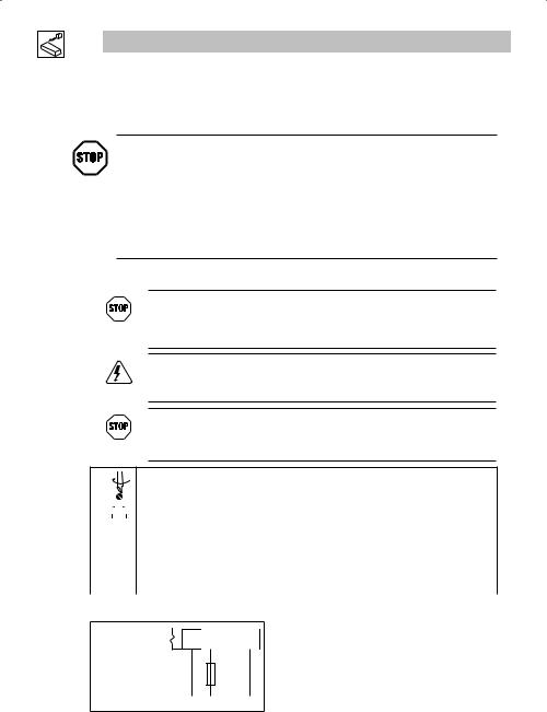
Installation
3.2Electrical Installation
Installation After a Long Period of Storage
STOP!
Severe damage to the drive can result if it is operated after a long period of storage or inactivity without reforming the DC bus capacitors.
If input power has not been applied to the drive for a period of time exceeding three years (due to storage, etc), the electrolytic DC bus capacitors within the drive can change internally, resulting in excessive leakage current. This can result in premature failure of the capacitors if the drive is operated after such a long period of inactivity or storage.
In order to reform the capacitors and prepare the drive for operation after a long period of inactivity, apply input power to the drive for 8 hours prior to actually operating the motor.
3.2.1Power Connections
STOP!
If the kVA rating of the AC supply transformer is greater than 10 times the input kVA rating of the drive(s), an isolation transformer or 2-3% input line reactor must be added to the line side of the drive(s).
DANGER! Hazard of electrical shock!
Circuit potentials up to 600 VAC are possible. Capacitors retain charge after power is removed. Disconnect power and wait at least three minutes before servicing the drive.
STOP!
•Verify mains voltage before connecting to drive.
•Do not connect mains power to the output terminals (U,V,W)! Severe damage to the drive will result.
•Do not cycle mains power more than once every two minutes. Damage to the drive may result.
Mains and Motor Terminations
|
|
|
|
|
Type |
Torque |
Strip Length |
|
|
|
|
|
|
|
|
|
|
|
|
|
<5HP |
12 lb-in (1.3 Nm) |
5/16 in (8mm) |
|
|
|
|
|
ESV552xx2T, ESV752xx2T, ESV113xx4/6, ESV153xx4/6, ESV183xx6, ESV223xx6 |
16 lb-in (1.8 Nm) |
5/16 in (8mm) |
|
|
|
|
|
|
|
|
|
|
|
|
|
ESV552xx4Txx, ESV752xx4Txx, ESV552xx6Txx, ESV752xx6Txx |
12 lb-in (1.3Nm) |
0.25 in (6mm) |
|
|
|
|
|
|
|
|
|
|
|
|
|
ESV113xx2xxx, ESV153xx2xxx, ESV183xx4xxx, ESV223xx4xxx, ESV303xx4xxx |
24 lb-in (2.7 Nm) |
7/16 in (10mm) |
|
|
|
|
|
|
|
|
|
|
|
|
|
ESV373xx4xxx, ESV453xx4xxx |
27 lb-in (3.05 Nm) |
0.75 in (19mm) |
|
|
|
|
|
|
|
|
|
|
|
|
|
Torque: N4X/IP65 Door Screws |
|
|
|
|
|
|
|
|
|
|
|
|
|
|
|
N4X/IP65 |
6-7 lb-in (0.67-0.79 Nm) |
0.25 in (6mm) |
|
|
|
|
|
|
|
|
3.2.1.1Mains Connection to 120VAC Single-Phase Supply
ESV...N01S...
PE L1 L2 N
PE L1 N
16 Lenze SMVector 13465100 EDBSV01 EN v18
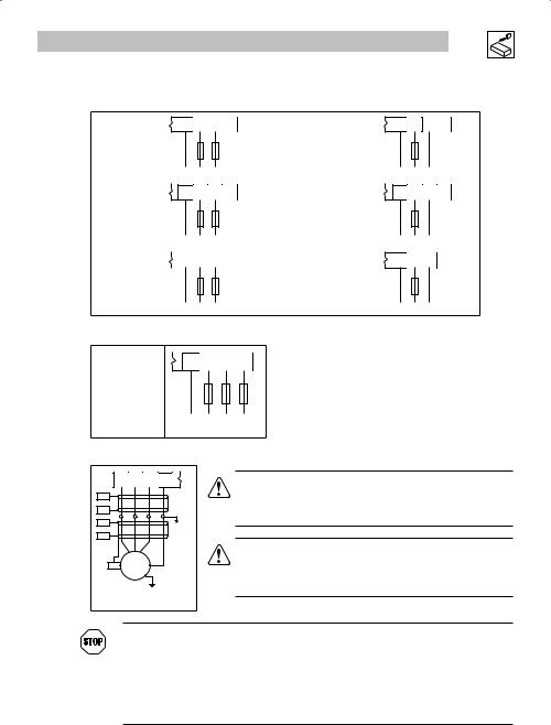
Installation
3.2.1.2Mains Connection to 240VAC Single-Phase Supply

 PE L1 L2 N
ESV...N01S... |
ESV...N01S... |
PE L1 L2
PE L1 |
L2 |
L3 |
ESV... |
N02Y... |
|
|
ESV... |
N02Y... |
||
(2/PE AC) |
|
|
(1/N/PE AC) |
||||
|
|
|
PE |
L1 |
L2 |
|
|
|
|
|
|
|
|
|
|
|
|
|
PE |
L1 |
L2 |
|
|
ESV... |
N02S... |
|
|
ESV... |
N02S... |
||
(2/PE AC) |
|
|
(1/N/PE AC) |
||||
|
|
|
PE |
L1 |
L2 |
|
|

 PE L1 L2 N
PE L1 N
PE L1 |
L2 |
L3 |
PE L1 N

 PE L1 L2
PE L1 N
3.2.1.3Mains Connection to Three-Phase Supply
ESV... |
N02Y... |
PE L1 |
L2 |
L3 |
||
ESV |
N02T |
|||||
|
|
|
|
|||
ESV... |
N04T... |
|
|
|
|
|
ESV... |
N06T... |
|
|
|
|
|
(3/PE AC) |
|
|
|
|
||
|
|
PE |
L1 |
L2 |
L3 |
|
3.2.1.4Motor Connection
U/T1 V/T2 W/T3 PE |
||
PES |
|
|
PES |
PE |
|
PES |
||
|
||
PES |
|
|
PES |
M |
|
3~ |
||
|
||
|
PE |
|
PES = Protective Earth Shielding |
||
WARNING!
If the cable connection between the drive and the motor has an in-line contactor or circuit breaker then the drive must be stopped prior to opening/closing the contacts. Failure to do so may result in 0vercurrent trips and/or damage to the inverter.
WARNING!
Leakage current may exceed 3.5 mA AC. The minimum size of the protective earth (PE) conductor shall comply with local safety regulations for high leakage current equipment.
STOP!
In the case of a Spinning Motor:
To bring free-wheeling loads such as fans to a rest before starting the drive, use the DC injection braking function. Starting a drive into a freewheeling motor creates a direct short-circuit and may result in damage to the drive.
Confirm motor suitability for use with DC injection braking.
Consult parameter P110 for starting / restarting into spinning motors.
Lenze SMVector 13465100 EDBSV01 EN v18 |
17 |
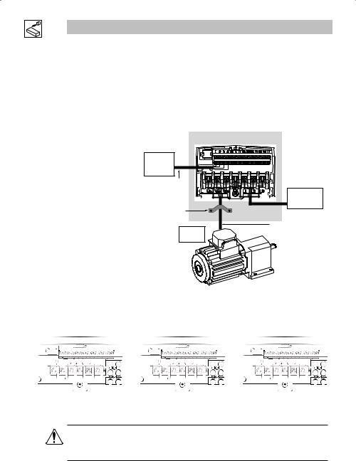
Installation
3.2.1.5Installation Recommendations for EMC Compliance
For compliance with EN 61800-3 or other EMC standards, motor cables, line cables and control or communications cables must be shielded with each shield/screen clamped to the drive chassis. This clamp is typically located at the conduit mounting plate.
The EMC requirements apply to the final installation in its entirety, not to the individual components used. Because every installation is different, the recommended installation should follow these guidelines as a minimum. Additional equipment (such as ferrite core absorbers on power conductors) or alternative practices may be required to meet conformance in some installations.
Motor cable should be low capacitance (core/core <75pF/m, core/shield <150pF/m). Filtered drives can meet the class A limits of EN 55011 and EN 61800-3 Category 2 with this type of motor cable up to 10 meters.
NOTE: Refer to Appendix A for recommended cable lengths. Any external line filter should have its chassis connected to the drive chassis by mounting hardware or with the shortest possible wire or braid.
Enclosure / Backplate
External
Control
Circuits
Control and signal cabling |
should be separated from |
power cables by |
a minimum of 300mm |
360° shield termination to |
backplate using saddle clamp |
From |
Motor |
From
AC Supply
Screened motor cable: core/core <75pF/M core/shield <150pF/M
3.2.1.6NEMA 4X (IP65) Input Terminal Block
For NEMA 4X (IP65) models with integrated EMC filter and/or integrated line disconnect, the input terminal block is located on the right-hand side of the SMV inverter in the NEMA 4 X (IP65) enclosure. The single and three phase models are illustrated herein. Refer to paragraph 3.2.3 Control Terminals for pin out information.
1 |
2 |
17 |
1 |
17 |
1 |
2 |
17 |
|
|
|
L1 |
|
|
|
|
L1 |
|
|
|
L1 |
|
|
|
L2 |
|
|
|
|
|
|
|
|
L2 |
U |
V W |
PE |
N |
U |
V |
W |
PE |
L2 |
U |
V W |
PE |
L3 |
|
|
|
|
|
|
|
|
|
|
Single Phase (2/PE) 120/240 VAC models |
Single Phase (2/PE) 240 VAC models |
Three Phase (3/PE) models |
(ESVxxxN01SMC) with integrated line |
with Filter and/or integrated line |
with Filter and/or integrated line |
disconnect |
disconnect |
disconnect |
WARNING
Power remains present for up to 3 minutes on power input terminals (L1, L2 and L3) and output terminals (U, V and W) even when the disconnect switch is in the OFF position. Remove input power ahead of the drive and wait 3 minutes before removing the terminal cover.
18 |
Lenze SMVector 13465100 EDBSV01 EN v18 |
 Loading...