


 Loading...
SERVICE MANUAL
CD RECEIVER
KD-SH9101, KD-SH9102, KD-SH9103, KD-SH9104


 Detachable
ATT
 ANGLE
ANGLE
|
|
EQ |
|
|
CD |
|
|
|
|
DAB |
DISC |
|
|
|
FM |
|
|
|
|
PRESET |
|
PRESET |
|
|
AM |
R D |
|
|
|
|
|
|
MOSFET |
KD-SH9101 |
CH |
|
SRC |
D |
|
|
DISC |
|
DISP |
|
AUX |
SEL |
ATT |
|
T/P |
|
VOLUME |
|
|
|
|
|
|
|
|
|
|
MODE |
SEL |
1 |
2 |
3 |
4 |
5 |
6 |
M |
RM-RK100
|
Area Suffix |
E ------ |
ContinentalEurope |
EX --------- |
Central Europe |
|
|
TABLE OF CONTENTS
1 Precautions . . . . . . . . . . . . . . . . . . . . . . . . . . . . . . . . . . . . . . . . . . . . . . . . . . . . . . . . . . . . . . . . . . . . . . . . . . 1-3 2 SPECIFIC SERVICE INSTRUCTIONS . . . . . . . . . . . . . . . . . . . . . . . . . . . . . . . . . . . . . . . . . . . . . . . . . . . . . . 1-5 3 Disassembly method . . . . . . . . . . . . . . . . . . . . . . . . . . . . . . . . . . . . . . . . . . . . . . . . . . . . . . . . . . . . . . . . . . 1-6 4 Adjustment. . . . . . . . . . . . . . . . . . . . . . . . . . . . . . . . . . . . . . . . . . . . . . . . . . . . . . . . . . . . . . . . . . . . . . . . . . 1-30 5 TROUBLESHOOTING . . . . . . . . . . . . . . . . . . . . . . . . . . . . . . . . . . . . . . . . . . . . . . . . . . . . . . . . . . . . . . . . . 1-33
COPYRIGHT © 2003 VICTOR COMPANY OF JAPAN, LIMITED
No.49841B
2003/11
|
SPECIFICATION |
|
|
||
|
|
|
|
||
|
AUDIO AMPLIFIER SECTION |
|
|
||
|
|
|
|
||
Maximum Power Output |
Front |
50 W per channel |
|
||
|
|
|
|
||
Rear |
50 W per channel |
|
|||
|
|
||||
|
|
|
|||
|
Front |
19 W per channel into 4Ω , 40 Hz to 20 000 Hz at no more |
|||
|
than 0.8% total harmonic distortion. |
||||
Continuous Power Output (RMS) |
|
||||
|
|
|
|
||
Rear |
19 W per channel into 4Ω , 40 Hz to 20 000 Hz at no more |
||||
|
|||||
|
than 0.8% total harmonic distortion. |
||||
|
|
||||
|
|
|
|
|
|
Load Impedance |
4Ω (4Ω to 8Ω allowance) |
|
|
|
|
|
|
||||
Equalizer Control Range |
Frequencies: 60 Hz, 150 Hz, 400 Hz, 1 kHz, 2.4 kHz, 6 kHz, 12 kHz |
||||
|
|
|
|
|
|
Level |
±10 dB |
|
|
|
|
|
|
|
|
|
|
Frequency Response |
40 Hz to 20 000 Hz |
|
|
|
|
|
|
|
|
|
|
Signal-to-Noise Ratio |
70 dB |
|
|
|
|
|
|
|
|
||
Line-In Level/Impedance |
LINE IN |
1.5 V/20 kΩ load |
|
||
|
|
|
|
|
|
Line-Out Level/Impedance |
4.0 V/20 kΩ load (full scale) |
|
|
|
|
|
|
|
|
|
|
Output Impedance |
1 kΩ |
|
|
|
|
|
|
|
|
|
|
|
TUNER SECTION |
|
|
|
|
|
|
|
|||
|
FM |
87.5 MHz to 108.0 MHz |
|||
Frequency Range |
|
|
|||
AM |
(MW) 522 kHz to 1 620 kHz |
||||
|
|
|
|
||
|
(LW) 144 kHz to 279 kHz |
||||
|
|
||||
|
|
|
|||
|
Usable Sensitivity |
11.3 dBf (1.0µV/75Ω ) |
|||
|
|
|
|||
|
50 dB Quieting Sensitivity |
16.3 dBf (1.8µV/75Ω ) |
|||
|
|
|
|
|
|
[FM Tuner] |
Alternate Channel Selectivity (400 kHz) |
65 dB |
|
|
|
|
|
|
|
||
Frequency Response |
40 Hz to 15 000 Hz |
|
|||
|
|
||||
|
|
|
|
|
|
|
Stereo Separation |
30 dB |
|
|
|
|
|
|
|
|
|
|
Capture Ratio |
1.5 dB |
|
|
|
|
|
|
|
|
|
[MW Tuner] |
Sensitivity |
20 µV |
|
|
|
|
|
|
|
||
Selectivity |
35 dB |
|
|
||
|
|
|
|||
|
|
|
|
|
|
[LW Tuner] |
Sensitivity |
50 µV |
|
|
|
|
|
|
|
|
|
|
CD PLAYER SECTION |
|
|
||
|
|
|
|
|
|
Type |
Compact disc player |
|
|
|
|
|
|
|
|
||
Signal Detection System |
Non-contact optical pickup (semiconductor laser) |
|
|
||
|
|
|
|
|
|
Number of channels |
2 channels (stereo) |
|
|
|
|
|
|
|
|
|
|
Frequency Response |
5 Hz to 20 000 Hz |
|
|
|
|
|
|
|
|
|
|
Dynamic Range |
98 dB |
|
|
|
|
|
|
|
|
|
|
Signal-to-Noise Ratio |
102 dB |
|
|
|
|
|
|
|
|
|
|
Wow and Flutter |
Less than measurable limit |
|
|
|
|
|
|
|
|
|
|
MP3 (MPEG Audio Layer 3) Max. |
320 Kbps |
|
|
|
|
Bit rate |
|
|
|
|
|
WMA (Windows Media(R) Audio) |
192 Kbps |
|
|
|
|
Max. Bit rate |
|
|
|
||
|
|
|
|
||
|
|
|
|
|
|
|
GENERAL |
|
|
|
|
|
|
|
|
||
Power Requirement |
Operating Voltage: DC 14.4 V (11 V to 16 V allowance) |
|
|||
|
|
|
|
|
|
Grounding System |
Negative ground |
|
|
|
|
|
|
|
|
|
|
Allowable Operating Temperature |
0°C to +40°C |
|
|
|
|
|
|
|
|
|
|
Dimensions (W × H × D) |
Installation Size: |
182 mm × |
52 mm × |
161 mm |
|
|
Panel Size: |
188 mm × |
58 mm × |
17 mm |
|
|
|
|
|
|
|
Mass |
1.8 kg (excluding accessories) |
|
|
|
|
|
|
|
|
|
|
Design and specifications are subject to change without notice. 1-2 (No.49841B)
SECTION 1
Precautions
1.1Safety Precautions
!


 Burrs formed during molding may be left over on some parts of the chassis. Therefore,
pay attention to such burrs in the case of preforming repair of this system.
! |
Please use enough caution not to see the beam directly or touch it in case of an |
|
adjustment or operation check. |
|
|
(No.49841B)1-3
1.2Preventing static electricity
Electrostatic discharge (ESD), which occurs when static electricity stored in the body, fabric, etc. is discharged, can destroy the laser diode in the traverse unit (optical pickup). Take care to prevent this when performing repairs.
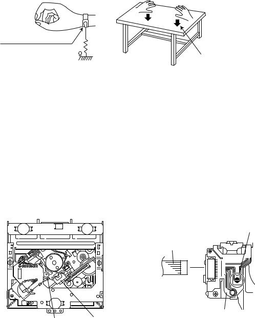
1.2.1Grounding to prevent damage by static electricity
Static electricity in the work area can destroy the optical pickup (laser diode) in devices such as CD players. Be careful to use proper grounding in the area where repairs are being performed.
(1)Ground the workbench
Ground the workbench by laying conductive material (such as a conductive sheet) or an iron plate over it before placing the traverse unit (optical pickup) on it.
(2)Ground yourself
Use an anti-static wrist strap to release any static electricity built up in your body.
(caption)
Anti-static wrist strap
1M
Conductive material (conductive sheet) or iron plate
(3)Handling the optical pickup
•In order to maintain quality during transport and before installation, both sides of the laser diode on the replacement optical pickup are shorted. After replacement, return the shorted parts to their original condition.
(Refer to the text.)
•Do not use a tester to check the condition of the laser diode in the optical pickup. The tester's internal power source can easily destroy the laser diode.
1.3Handling the traverse unit (optical pickup)
(1)Do not subject the traverse unit (optical pickup) to strong shocks, as it is a sensitive, complex unit.
(2)Cut off the shorted part of the flexible cable using nippers, etc. after replacing the optical pickup. For specific details, refer to the replacement procedure in the text. Remove the anti-static pin when replacing the traverse unit. Be careful not to take too long a time when attaching it to the connector.
(3)Handle the flexible cable carefully as it may break when subjected to strong force.
(4)It is not possible to adjust the semi-fixed resistor that adjusts the laser power. Do not turn it.
1.4Attention when traverse unit is decomposed
*Please refer to "Disassembly method" in the text for the CD pickup unit.
•Apply solder to the short land before the flexible wire is disconnected from the connector on the CD pickup unit. (If the flexible wire is disconnected without applying solder, the CDpickup may be destroyed by static electricity.)
•In the assembly, be sure to remove solder from the short land after connecting the flexible wire.
Short-circuit point (Soldering)
Flexible wire
Pickup
Short-circuit point Pickup
1-4 (No.49841B)
SECTION 2
SPECIFIC SERVICE INSTRUCTIONS
This service manual does not describe SPECIFIC SERVICE INSTRUCTIONS.
(No.49841B)1-5
SECTION 3
Disassembly method
3.1 Main body section
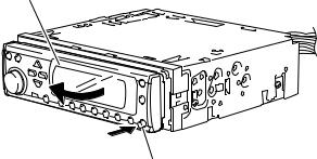
3.1.1Removing the front panel assembly (See Fig.1)
(1) |
Push the detach button in the lower right part of the front |
|
|
panel assembly. |
Front panel assembly |
(2) |
Remove the front panel assembly in the direction of the ar- |
|
|
row. |
|
Detach button
Fig.1
1-6 (No.49841B)

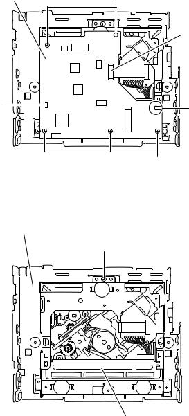
3.1.2Removing the top chassis (See Figs.2 to 6)
•Turn on power.
(1)Push the eject button in the upper right part of the front panel assembly to move the front panel assembly as shown in Fig.2 and turn off power.
(2)Remove the two screws A attaching the top chassis from the top side of the main body. (See Fig.3.)
(3)Remove the three screws B attaching the top chassis from the both sides of the main body. (See Figs.4 and 5.)
(4)Remove the screw C and three screws D attaching the heat sink from the left side of the main body. (See Fig.5.)
(5)Remove the two screws E and screw F attaching the top chassis from the back side of the main body. (See Fig.6.)
(6)Move the top chassis upward and remove it with the CD mechanism assembly. The connector CN501 on the CD mechanism assembly is disconnected from the connector CN981 on the main board.
Top chassis
Front panel assembly
Eject button
Fig.2
Top chassis
A |
A |
Top chassis
|
|
|
|
|
|
|
|
|
|
|
|
|
|
|
|
|
|
|
|
|
|
|
|
|
|
|
|
|
|
|
|
|
|
|
|
|
|
|
|
|
|
|
|
|
|
|
|
|
|
|
|
|
|
|
|
|
|
|
|
|
|
|
|
|
|
|
|
|
|
|
|
|
|
|
|
|
|
|
|
|
|
|
|
|
|
B |
|
|
|
|
|
|
B |
||||
|
|
|
|
|
Fig.4 |
||||||||
C |
|
|
|
|
|
Top chassis |
|||||||
|
|
|
|
|
|
|
|
|
|||||
|
|
|
|
|
|
|
|
|
|
|
|
|
|
|
|
|
|
|
|
|
|
|
|
|
|
|
|
|
|
|
|
|
|
|
|
|
|
|
|
|
|
|
|
|
|
|
|
|
|
|
|
|
|
|
|
|
|
|
|
|
|
|
|
|
|
|
|
|
|
|
|
|
|
|
|
|
|
|
|
|
|
|
|
|
|
|
|
|
|
|
|
|
|
|
|
|
|
|
|
|
|
|
|
|
|
|
|
|
|
|
|
|
|
|
|
|
|
|
|
|
|
|
|
|
|
|
|
|
|
|
|
|
|
|
|
|
|
|
|
Heat sink |
|
D |
|
B |
|
|
|
|
Fig.5 |
||
|
E |
|
F |
||
|
|
|
|
|
|
|
|
|
|
|
|
|
|
|
|
|
|
Fig.6
Front panel assembly
Fig.3
(No.49841B)1-7
3.1.3 Removing the mecha control board (See Fig.7)
•Prior to performing the following procedures, remove the top chassis.
(1)Disconnect the card wire from the connector CN601 on the mecha control board.
(2)Remove the five screws G attaching the mecha control board.
(3)Release the joints a and b, remove the mecha control board.
Mecha control board
a
G
CN601
b
3.1.4Removing the CD mechanism assembly (See Fig.8)
•Prior to performing the following procedure, remove the top chassis.
(1)Remove the three screws H from the inside of the top chassis and remove the CD mechanism assembly.
G
Fig.7
Top chassis
H
H 
 H
H
CD mechanism assembly
Fig.8
1-8 (No.49841B)
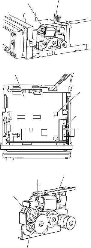
3.1.5Removing the motor assembly (See Figs.9 to 11)
•Prior to performing the following procedures, remove the top chassis.
(1)Remove the spring from the motor bracket. (See Fig.9.)
(2)Disconnect the wire from the connector CN982 on the main board. (See Fig.10.)
(3)Remove the two screws J attaching the motor bracket. (See Fig.10.)
(4)Remove the washer attaching the clutch assembly and pull out the clutch assembly from the shaft. (See Fig.11.)
(5)Remove the two screws K attaching the motor assembly to the motor bracket. (See Fig.11.)
Motor braket
Spring
Fig.9
Main board
CN982
Motor braket
J
Fig.10
Motor braket
K
Clutch assembly
 Motor assembly
Washer
Fig.11
(No.49841B)1-9

3.1.6 Removing the main board (See Figs.12 to 16)
•Prior to performing the following procedures, remove the top chassis and motor assembly.
(1)Disconnect the flexible wires from the connectors CN703 and CN991 on the main board respectively. (See Fig.12.)
(2)Move the front bracket backward until it stops.
(3)Remove the four screws L attaching the arm brackets (L) and (R). Move the arm brackets (L) and (R) from the rod gear. (See Fig.12.)
(4)Remove the rod gear.
(5)Remove the screw M attaching the rear panel to the bottom cover from the back side of the main body. (See Fig.14.)
(6)Remove the three screws N attaching the main board and move the main board backwards to release the two joints c. (The main board will be removed with the rear panel and rear heat sink) (See Figs.12 and 15.)
(7)Remove the screw P and Q attaching the rear heat sink. (See Fig.16.)
(8)Remove the three screws R and screw S attaching the rear panel, then remove the main board. (See Fig.16.)
Rear panel |
|
|
Bottom cover |
|
M |
||||
|
|
|||
|
Fig.14 |
|
||
Joint c
Main board
Joint c
N Main board N
Arm |
|
brackets (L) |
|
Arm |
|
brackets (R) |
|
L |
Fig.15 |
|
|
L |
|
R |
P |
CN703 |
CN991 |
M |
Rod gear |
|
Fig.12 |
|
|
Arm brackets (L)
S Q
Rear panel |
Rear heat sink |
Fig.16
Arm brackets (R)
Main board
Rod gear
Fig.13
1-10 (No.49841B)
3.1.7 Removing the lifter switch board |
|
(See Fig.17) |
|
• Prior to performing the following procedure, remove the top |
|
chassis, motor assembly and main board. |
Bottom chassis |
(1) Remove the two screws T attaching the lifter switch board |
Lifter switch board |
|
|
to the bottom chassis. |
|
T
Fig.17
(No.49841B)1-11
Loading...