


JLG E300 Parts Manual

3121254 E300AJ/E300AJP 3
4 E300AJ/E300AJP 3121254
3121254 E300AJ/E300AJP 5


TABLE OF CONTENTS
SECTION 1 - FRAME ........................................................................................................................................................................... 9
FIGURE 1-1. STEER INSTALLATION ............................................................................................................................................ 10
FIGURE 1-2. TIRE AND WHEEL DRIVE INSTALLATION ............................................................................................................. 12
FIGURE 1-3. DRIVE HUB ASSEMBLY .......................................................................................................................................... 14
FIGURE 1-4. DRIVE MOTOR ASSEMBLY .................................................................................................................................... 18
FIGURE 1-5. ELECTRICAL COMPONENTS INSTALLATION (FRAME MOUNTED) .................................................................... 20
FIGURE 1-6. BATTERY BOX INSTALLATION .............................................................................................................................. 24
FIGURE 1-7. FRAME COVERS INSTALLATION ........................................................................................................................... 26
FIGURE 1-8. INVERTER INSTALLATION (OPTIONAL) ................................................................................................................ 28
SECTION 2 - TURNTABLE ................................................................................................................................................................ 31
FIGURE 2-1. CONTROL VALVES AND TANK/MOTOR INSTALLATIONS ................................................................................... 32
FIGURE 2-2. MAIN CONTROL VALVE ASSEMBLY ...................................................................................................................... 36
FIGURE 2-3. BOOM FUNCTION VALVE ASSEMBLY ................................................................................................................... 38
FIGURE 2-4. TURNTABLE AND SWING DRIVE INSTALLATION ................................................................................................. 40
FIGURE 2-5. TURNTABLE BEARING ASSEMBLY ....................................................................................................................... 42
FIGURE 2-6. SWING MOTOR ASSEMBLY ................................................................................................................................... 44
FIGURE 2-7. GROUND CONTROL BOX ASSEMBLY ................................................................................................................... 46
FIGURE 2-8. ELECTRICAL COMPONENTS INSTALLATIONS .................................................................................................... 50
FIGURE 2-9. HOODS INSTALLATION (Prior to SN 0300194887) ................................................................................................. 54
FIGURE 2-10. HOOD INSTALLATION (SN 0300194887 to Present) ............................................................................................ 56
SECTION 3 - BOOM .......................................................................................................................................................................... 59
FIGURE 3-1. BOOM AND CYLINDERS INSTALLATION ............................................................................................................... 60
FIGURE 3-2. TOWER BOOM ASSEMBLY .................................................................................................................................... 64
FIGURE 3-3. MAIN BOOM ASSEMBLY ......................................................................................................................................... 66
FIGURE 3-4. JIB ASSEMBLY AND PLATFORM SUPPORT INSTALLATION ............................................................................... 70
FIGURE 3-5. PLATFORM ROTATOR ASSEMBLY ........................................................................................................................ 74
FIGURE 3-6. JIB SWING ROTATOR ASSEMBLY (E300AJP ONLY) ............................................................................................ 76
FIGURE 3-7. CABLE, CLAMPS AND LIMIT SWITCHES INSTALLATION ..................................................................................... 78
SECTION 4 - PLATFORM .................................................................................................................................................................. 81
FIGURE 4-1. PLATFORM ASSEMBLY .......................................................................................................................................... 82
FIGURE 4-2. PLATFORM CONSOLE ASSEMBLY ........................................................................................................................ 86
FIGURE 4-3. CONTROLLER ASSEMBLY (DRIVE AND STEER) (Prior to SN 0300194240) ........................................................ 90
FIGURE 4-4. CONTROLLER ASSEMBLY (DRIVE AND STEER) (SN 0300194240 to Present) ................................................... 94
FIGURE 4-5. CONTROLLER ASSEMBLY (SWING AND LIFT) (Prior to SN 0300194240) ........................................................... 96
FIGURE 4-6. CONTROLLER ASSEMBLY (SWING AND LIFT) (SN 0300194240 to Present) .................................................... 100
SECTION 5 - CYLINDER ................................................................................................................................................................. 103
FIGURE 5-1. LEVEL (PLATFORM SLAVE) CYLINDER ASSEMBLY .......................................................................................... 104
FIGURE 5-2. LIFT (JIB) CYLINDER ASSEMBLY ......................................................................................................................... 106
FIGURE 5-3. LIFT (MAIN BOOM) CYLINDER ASSEMBLY ......................................................................................................... 108
FIGURE 5-4. LIFT (TOWER BOOM) CYLINDER ASSEMBLY ..................................................................................................... 110
FIGURE 5-5. MASTER CYLINDER ASSEMBLY .......................................................................................................................... 112
FIGURE 5-6. STEER CYLINDER ASSEMBLY ............................................................................................................................. 114
FIGURE 5-7. TELESCOPE CYLINDER ASSEMBLY ................................................................................................................... 116
SECTION 6 - HYDRAULIC .............................................................................................................................................................. 119
FIGURE 6-1. HYDRAULIC DIAGRAM - E300AJ .......................................................................................................................... 120
FIGURE 6-2. DRIVE HYDRAULIC DIAGRAM - E300AJP ............................................................................................................ 122
FIGURE 6-3. HYDRAULIC DIAGRAM LIST ................................................................................................................................. 124
SECTION 7 - ELECTRICAL ............................................................................................................................................................. 125
FIGURE 7-1. ELECTRICAL DIAGRAM LIST ................................................................................................................................ 126
FIGURE 7-2. HARNESS COMPONENTS INSTALLATION .......................................................................................................... 128
SECTION 8 - DECALS ..................................................................................................................................................................... 141
3121254 E300AJ/E300AJP 7

TABLE OF CONTENTS
FIGURE 8-1. DECAL INSTALLATION (ANSI SPEC) .................................................................................................................... 142
FIGURE 8-2. DECAL INSTALLATION (COUNTRY SPECS) ........................................................................................................ 146
FIGURE 8-3. DECAL INSTALLATION (AUSTRALIAN/CE SPECS) ............................................................................................. 152
SECTION 9 - RECOMMENDED SERVICE PARTS STOCK ............................................................................................................ 157
FIGURE 9-1. MODELS E300AJ AND E300AJP STANDARD PARTS .......................................................................................... 158
FIGURE 9-2. MODELS E300AJ AND E300AJP VARIABLE PARTS ............................................................................................ 160
SECTION 10 - SPECIAL OPTION .................................................................................................................................................... 161
FIGURE 10-1. SPECIAL OPTIONS .............................................................................................................................................. 162
PART NUMBER INDEX .................................................................................................................................................................... 165
8 E300AJ/E300AJP 3121254

SECTION 1 - FRAME
SECTION 1 - FRAME
3121254 E300AJ/E300AJP 9
SECTION 1 - FRAME
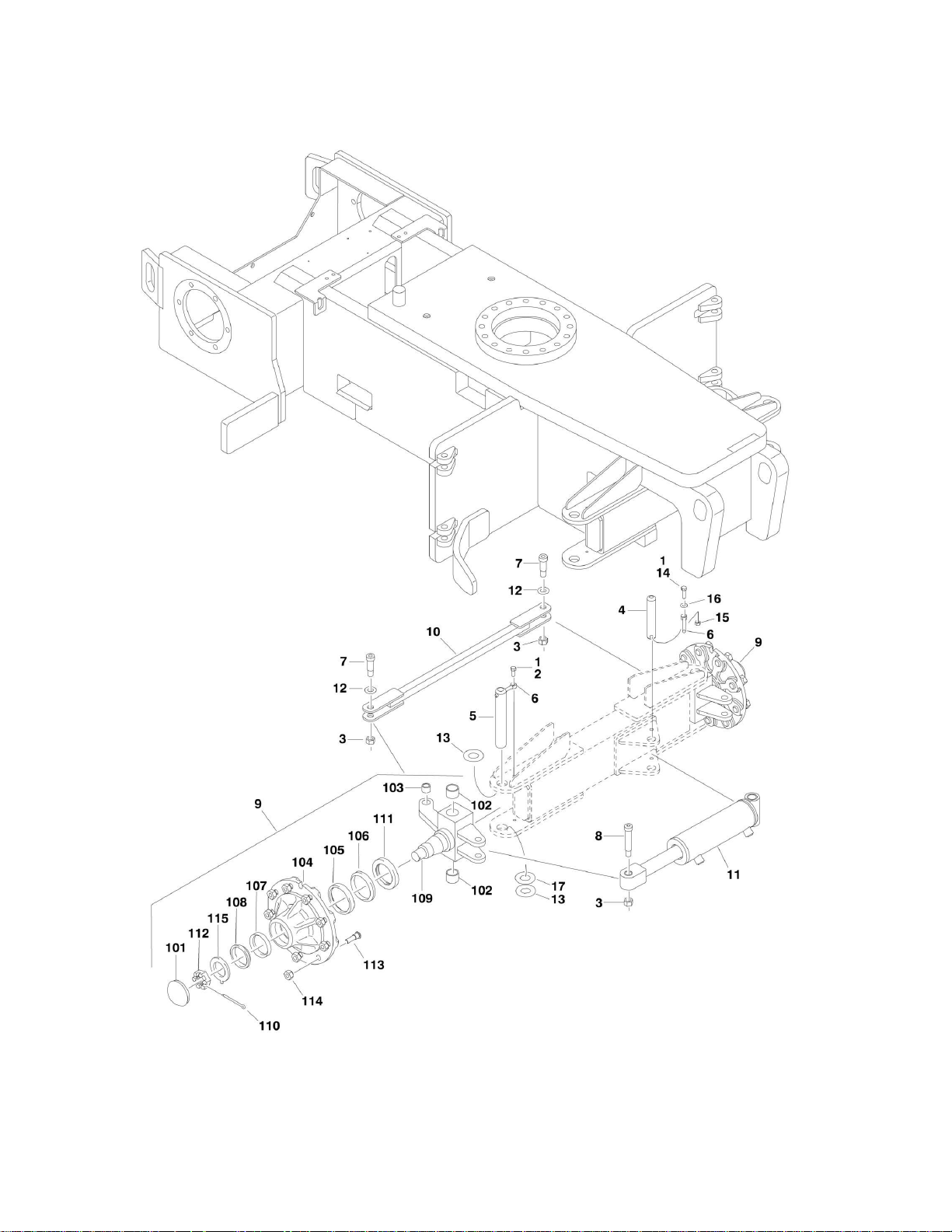
FIGURE 1-1. STEER INSTALLATION
10 E300AJ/E300AJP 3121254

FIGURE 1-1. STEER INSTALLATION
ITEM
PART NUMBER
QTY
DESCRIPTION
REV
1001108599
Ref
STEER INSTALLATION
C 1 0100011
AR
Compound, Locking
2 0641607
2
Bolt 3/8in-16NC x 7/8in
3 3312005
3
Locknut 5/8in-11NC
4 3422181
1
Pin 5
3422562
2
Pin 6
3841143
3
Keeper, Pin
7 3900118
2
Screw, Shoulder
8 3900255
1
Capscrew, Shoulder 3/4in x 3in
9 1001107712
2
Hub/Spindle Assembly (See Items 101-115 for Breakdown)
10
1001107727
1
Tie-Rod
11
1001108310
1
Steer Cylinder Assembly (See CYLINDER SECTION for
Breakdown)
12
4740086
2
Thrustwasher
13
0440162
4
Thrustwasher
14
0641610
1
Bolt 3/8in-16NC x 1-1/4in
15
3311605
1
Locknut 3/8in-16NC
16
4711600
1
Flatwasher 3/8in Thin
17
1001151428
AR
Plate, Shim (SN 0300176716 to Present)
1001107712
Ref
HUB/SPINDLE ASSEMBLY
A
Ref
Note: Qty shown is for 1 Hub Assembly. Machine requires 2
assemblies.
101
7020137
1
Cap, Dust
102
0961951
2
Bushing, Garmax
103
0962140
1
Bearing, Garmax
104
70002434
1
Hub 105
7020036
1
Cup, Bearing (Inner) (Part of Item 104)
106
7020037
1
Cone, Bearing (Inner)
107
7020038
1
Cup, Bearing (Outer) (Part of Item 104)
108
7020039
1
Cone, Bearing (Outer)
109
70002435
1
Spindle
110
7020140
1
Pin, Cotter
111
7020040
1
Seal 112
7020054
1
Nut, Castle 1-1/4in-12
113
7020041
9
Stud 5/8in-18NF
114
7020042
9
Lugnut 5/8in-18NF
115
7020055
1
Washer, Tanged 1-1/4in
SECTION 1 - FRAME
3121254 E300AJ/E300AJP 11
SECTION 1 - FRAME
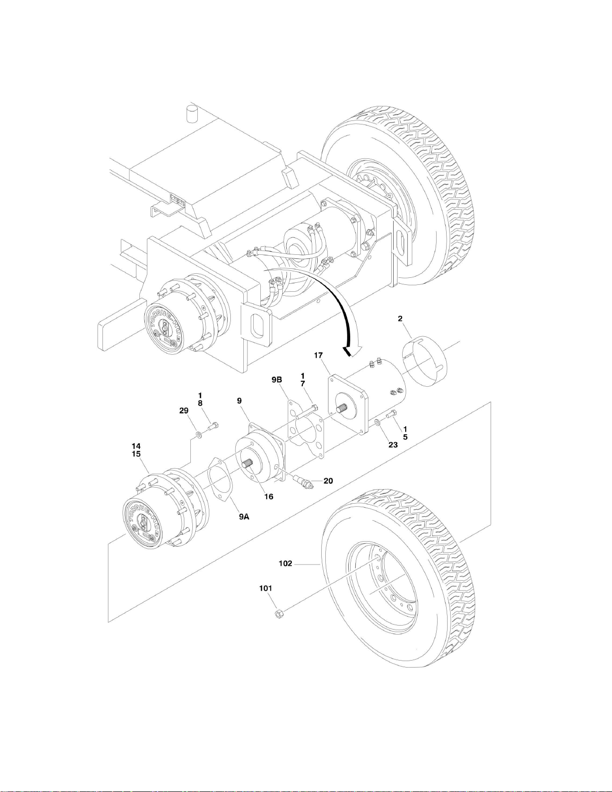
FIGURE 1-2. TIRE AND WHEEL DRIVE INSTALLATION
12 E300AJ/E300AJP 3121254

SECTION 1 - FRAME
ITEM
PART NUMBER
QTY
DESCRIPTION
REV
Ref
WHEEL DRIVE INSTALLATION OPTIONS:
1001109430
Ref
Standard Spec
F 1001109431
Ref
UL Spec
H 1 0100019
AR
Compound, Locking
2 0340047
2
Band, Motor (UL Spec Only)
5 0641609
8
Bolt 3/8in-16NC x 1-1/8in
7 0641826
4
Bolt 1/2in-13NC x 3-1/2in
8
0682012
12
Bolt 5/8in-11NC x 1-1/2in (SN 0300113683 through
0300138358)
9
0920113
2
Drive Brake Assembly
9
0920113
2
Ring, Sensor (1 Per Assembly) (was p/n 7027275 which is no
longer available. Replace Complete Brake.)
9
7007977
2
Ring, Bearing Retaining (Large) (1 per Assembly)
9 7011716
2
Ring, Bearing Retaining (Small) (1 per Assembly)
9 7007913
4
Bolt
9
7011757
2
Complete Repair Kit (Includes Case and Oil Seals, O-Rings,
Back-Up Rings, Stator and Rotor Discs, Return Plate, Springs,
Bearing and Brake To Hub Gasket) (1 Per Assembly)
9
2900768
2
Bearing Kit (1 per Assembly)
9 7007900
2
Seal, Oil - Front (1 per Assembly)
9A
7007933
2
Gasket (1 Per Assembly)
9B
70002408
2
Gasket, Brake to Motor (1 Per Assembly) (Not Included in
Repair Kit)
14
2780282
2
Drive Hub Assembly (See DRIVE HUB ASSEMBLY for
Breakdown)
15
3020008
AR
Lubricant, Mobilube HD 80W-90
16
3020037
AR
Lube, Coupling Grease
17
3160237
2
Drive Motor Assembly (See DRIVE MOTOR ASSEMBLY for
Breakdown)
20
3990105
2
Speed Sensor Assembly
23
4711600
8
Flatwasher 3/8in Thin
29
4892000
12
Flatwasher 5/8in Hardened
0258986
Ref
TIRE AND WHEEL INSTALLATION
C
101
3300106
18
Lugnut 102
1001110772
4
Tire and Wheel Assembly
FIGURE 1-2. TIRE AND WHEEL DRIVE INSTALLATION
3121254 E300AJ/E300AJP 13
SECTION 1 - FRAME
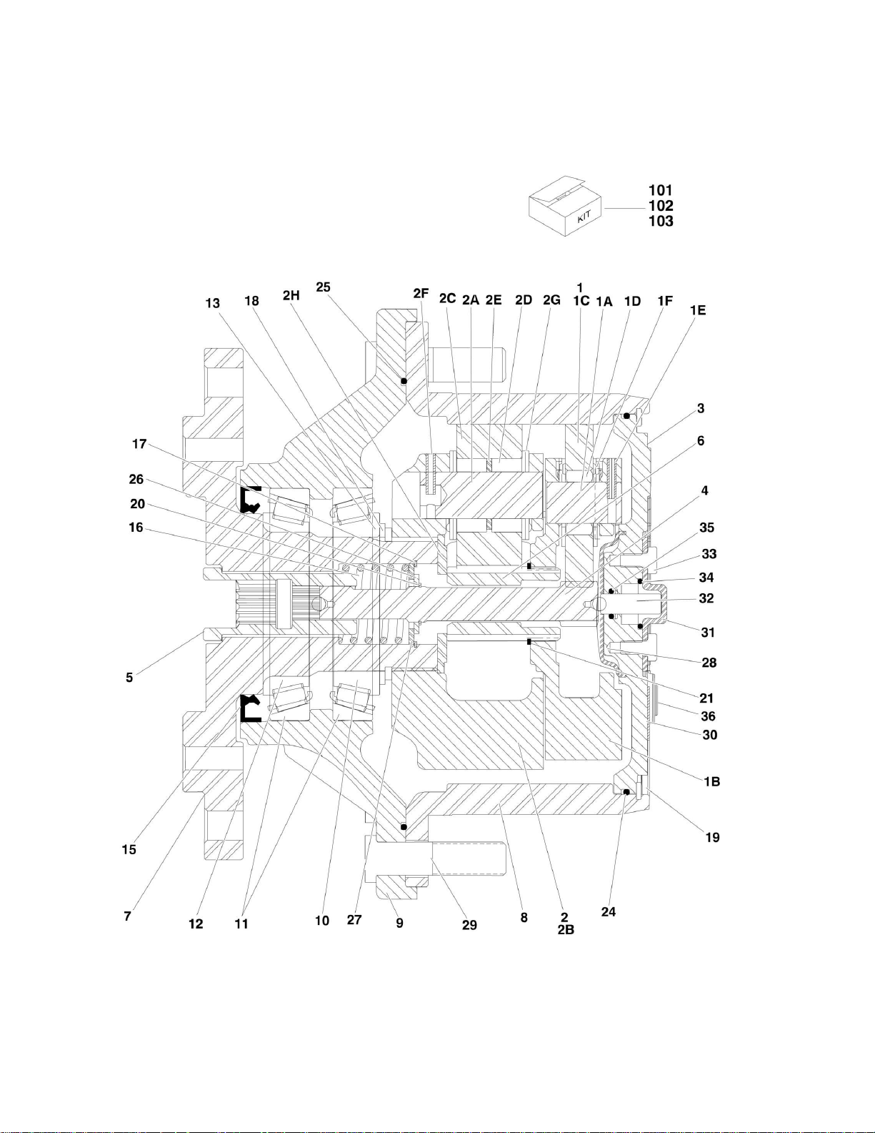
FIGURE 1-3. DRIVE HUB ASSEMBLY
14 E300AJ/E300AJP 3121254

FIGURE 1-3. DRIVE HUB ASSEMBLY
ITEM
PART NUMBER
QTY
DESCRIPTION
REV
2780282
Ref
DRIVE HUB ASSEMBLY
B 1 70001366
1
Carrier, Sub Assembly (Purchase p/n 70001366 for items 1A-1F)
1A
70001366
3
Shaft, Planet
1B
70001366
1
Carrier
1C
70001366
3
Gear, Planet
1D
70001366
42
Bearing, Needle
1E
70001366
3
Pin, Roll
1F
70001366
6
Thrustwasher
2 70001367
1
Carrier, Input (Purchase p/n 70001367 for items 2A-2H)
2A
70001367
3
Shaft, Planet
2B
70001367
1
Carrier
2C
70001367
3
Gear, Planet
2D
70001367
84
Bearing, Needle
2E
70001367
3
Spacer, Thrust
2F
70001367
3
Pin, Roll
2G
70001367
12
Thrustwasher
2H
70001367
1
Thrustwasher
3 70001368
1
Cover 4
70001369
1
Shaft, Input
5 70001370
1
Coupling
6 70001371
1
Shaft, Sun Gear
7 70001372
1
Spindle 8
70001373
1
Gear, Ring
9 2780282
1
Housing
10
7017007
1
Bearing, Tapered-Cone
11
7017007
2
Bearing, Tapered-Cup
12
7017007
1
Bearing, Tapered-Cone
13
7017009
1
Thrustwasher
15
70001380
1
Seal, Lip
16
70001374
1
Spring 17
70001375
1
Ring, Retaining (Internal)
18
70001380
1
Ring, Retaining (External)
19
7024738
1
Ring, Retaining (Internal)
20
70001376
1
Ring, Retaining (External)
21
70001377
1
Ring, Retaining (External)
22
7000281
4
Screw (Not Shown - ID plate screws)
23
7017022
3
Bolt, Flathead (Not Shown - Located on front of hub)
24
70001380
1
O-Ring 25
70001380
1
O-Ring 26
70001378
1
Spacer, Thrust
27
70001379
1
Thrustwasher
28
7024741
1
Spacer, Thrust
29
7007640
9
Stud, Wheel
30
70001368
1
Flange, Plate
31
70001368
1
Cap, Disengage
32
70001368
1
Pin, Dowel
33
70001368
2
Bolt 34
70001368
1
O-Ring 35
70001368
1
O-Ring 36
70001368
1
Plug
SECTION 1 - FRAME
3121254 E300AJ/E300AJP 15

ITEM
PART NUMBER
QTY
DESCRIPTION
REV
Ref
Kit Options
101
7017007
1
Planet Gear Bearing Kit (Includes Items 10-12)
102
70001380
1
Planet Gear Seal Kit (Includes Items 15, 18, 24 & 25)
103
70001368
1
Cap/Disengage Kit (Includes Items 30-36)
SECTION 1 - FRAME
16 E300AJ/E300AJP 3121254

SECTION 1 - FRAME
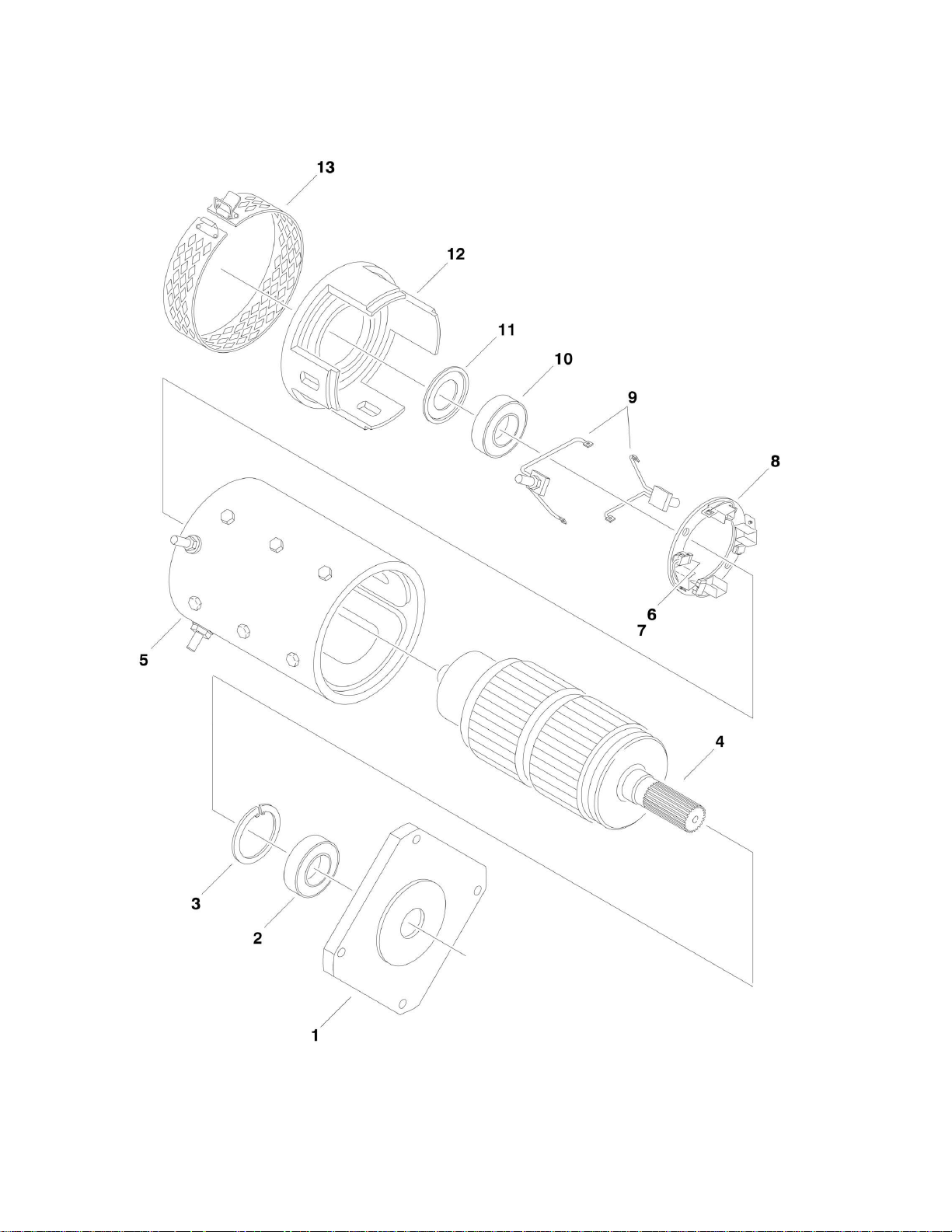
FIGURE 1-4. DRIVE MOTOR ASSEMBLY
18 E300AJ/E300AJP 3121254

FIGURE 1-4. DRIVE MOTOR ASSEMBLY
ITEM
PART NUMBER
QTY
DESCRIPTION
REV
3160237
Ref
DRIVE MOTOR ASSEMBLY
E 1 7020184
1
Plate, Drive End
2 7012545
1
Bearing 3
7020185
1
Ring, Retaining
4 3160237
1
Armature
5 3160237
1
Frame and Field Assembly
6 7012548
4
Spring, Brush
7 7020149
4
Brush 8
7020150
1
Holder, Brush
9 7020151
2
Brush Lead Assembly Kit
10
7012545
1
Bearing
11
7012549
1
Washer, Wavy
12
7020189
1
End, Commutator
13
7019609
1
Headband Assembly
SECTION 1 - FRAME
3121254 E300AJ/E300AJP 19
SECTION 1 - FRAME
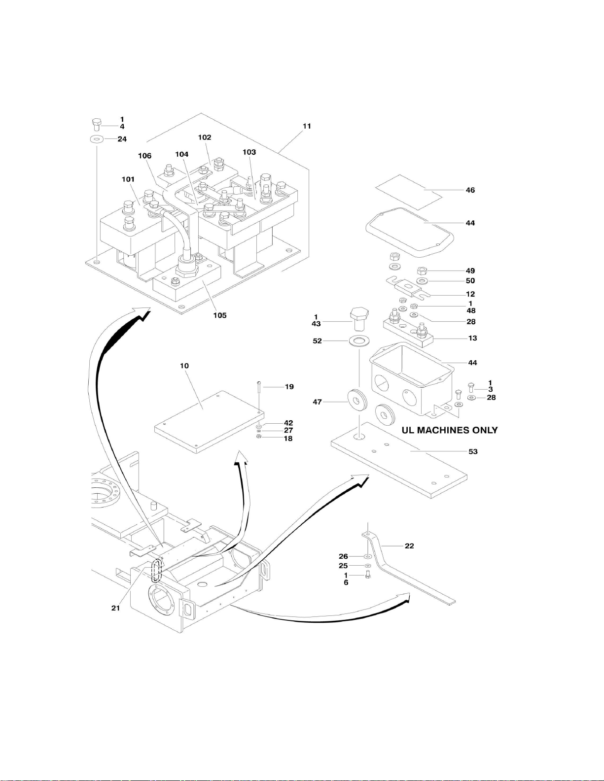
FIGURE 1-5. ELECTRICAL COMPONENTS INSTALLATION (FRAME MOUNTED)
20 E300AJ/E300AJP 3121254

SECTION 1 - FRAME
ITEM
PART NUMBER
QTY
DESCRIPTION
REV
Ref
ELECTRICAL COMPONENTS INSTALLATION
1001109430
Ref
Standard Spec
F 1001109431
Ref
UL Spec
H 1 0100019
AR
Compound, Locking
3 0721003
2
Screw #10-24NC x 3/8in (UL Spec Only)
4 0641504
4
Bolt 5/16in-18NC x 3/4in
6 0641610
1
Bolt 3/8in-16NC x 1-1/4in
10
1600293
1
Module (Note: Calibration is required when replaced)
11 Ref
Contactor Plate Assembly Options (See Items 101 to 106 for
Breakdown):
11
1600294
1
Standard Spec
11
1600300
1
UL Spec
12
2400062
1
Fuse, 300 Amp (UL Spec Only)
13
2400044
1
Holder, Fuse (UL Spec Only)
18
3310601
4
Nut #6-32NC
19
3910628
4
Screw #6-32NC x 1-3/4in
21
4060807
14
in/36cm
Shield, Flex Trim
22
4240084
1
Strap, Anti-Static
24
4751500
4
Flatwasher 5/16in Regular
25
4751600
1
Flatwasher 3/8in Regular
26
4752200
1
Flatwasher 3/4in Regular
27
4760600
4
Lockwasher #6
28
4751000
2
Flatwasher #10 Regular
41 Ref
Drive Cable System Cables Options (Not Shown - See
ELECTRICAL SECTION for Breakdown):
41
2901818
1
Standard Spec
41
2901864
1
UL Spec
42
4750600
4
Flatwasher #6 Regular
43
0642208
1
Bolt 3/4in-10NC x 1in
44
0861375
1
Box 46
1704712
1
Decal - 300 Amp Fuse
47
2540037
2
Grommet
48
3311001
2
Nut #10-24NC
49
3311501
2
Nut 5/16in-18NC
50
4711500
4
Flatwasher 5/16in Thin
52
4712200
1
Flatwasher 3/4in Thin
53
1001116273
1
Bracket
Ref
CONTACTOR PLATE ASSEMBLY
1600294
Ref
Standard Spec
1600300
Ref
UL Spec
Ref
Harness, Contactor Options (Not Shown) (See ELECTRICAL
SECTION for Breakdown):
7022003
1
Standard Spec
7022008
1
UL Spec
7022004
1
Harness, Posi-Track Contactor (Not Shown) (See ELECTRICAL
SECTION for Breakdown)
7022005
1
Harness, Shunt (Not Shown) (See ELECTRICAL SECTION for
Breakdown)
101
Ref
Contactor, FWD / REV Options:
101
7022002
1
Standard Spec
FIGURE 1-5. ELECTRICAL COMPONENTS INSTALLATION (FRAME MOUNTED)
3121254 E300AJ/E300AJP 21

ITEM
PART NUMBER
QTY
DESCRIPTION
REV
101
7022007
1
UL Spec
102
Ref
Contactor, Main Options:
102
7022001
1
Standard Spec
102
7022009
1
UL Spec
103
Ref
Contactor, Posi-Track Options:
103
7022000
1
Standard Spec
103
7022010
2
UL Spec
104
7022012
1
Cable, Power
105
7022011
1
Diode, Power
106
70001052
1
Shunt/Bus Bar With Harness Assembly
SECTION 1 - FRAME
22 E300AJ/E300AJP 3121254

SECTION 1 - FRAME
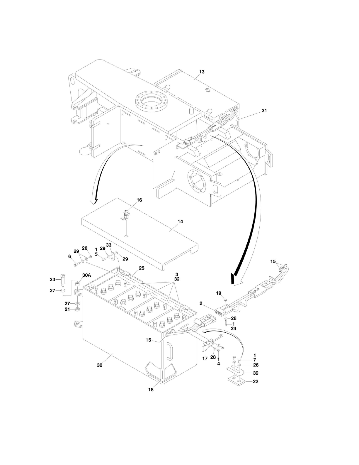
FIGURE 1-6. BATTERY BOX INSTALLATION
24 E300AJ/E300AJP 3121254

FIGURE 1-6. BATTERY BOX INSTALLATION
ITEM
PART NUMBER
QTY
DESCRIPTION
REV
Ref
BATTERIES INSTALLATION
1001108560
Ref
Machines with 305AH Batteries
B 1001115997
Ref
Machines with 305AH AGM Batteries
A 0259042
Ref
Machines with 375AH Batteries
J 1 0100011
AR
Compound, Locking
2 0100048
AR
Grease, Dialectric
3 0100051
AR
Grease, Battery Terminal
4 0641403
4
Bolt 1/4in-20NC x 3/8in
5 0641505
4
Bolt 5/16in-18NC x 5/8in (Machines with AGM Batteries Only)
6 Ref
Bolt 5/16in-18NC Options:
6 0641512
4
Bolt 5/16in-18NC x 1-1/2in
6 0641514
4
Bolt 5/16in-18NC x 1-3/4in
7 0641606
4
Bolt 3/8in-16NC x 3/4in
13
1670878
1
Cover, (Right)
14
1670890
1
Cover, (Left)
15
2540020
4
Grommet
16
2940073
2
Latch 17
2940114
2
Latch 18
3000003
2
Liner 19
3311401
4
Nut 1/4in-20NC
20
3311505
4
Locknut 5/16in-18NC (Machines with 305AH Batteries Only)
21
3312005
4
Locknut 5/8in-11NC
22
3340852
2
Pad 23
3900266
4
Screw, Shoulder
24
3931430
4
Bolt 1/4in-20NC x 1-7/8in
25
4567739
2
Tube
26
4711600
4
Flatwasher 3/8in Thin
27
4740086
8
Thrustwasher
28
4751400
8
Flatwasher 1/4in Regular
29
4751500
AR
Flatwasher 5/16in Regular
30
4845923
1
Box, Battery (Left)
30A
0962233
2
Bushing
31
4845924
1
Box, Battery (Right)
31A
0962233
2
Bushing (Not Shown)
32 Ref
Battery Options:
32
1001105091
8
Wet Battery (6V-305-S)
32
1001114782
8
Wet Battery (6V-305A-A AGM)
32
0400055
8
Wet Battery (6V-370-S)
32
See Note
8
Dry Battery (6V-305-S) (Note: Not Available for Purchase)
32
See Note
8
Dry Battery (6V-305A-A AGM) (Note: Not available for
purchase)
32
0400107
8
Dry Battery (6V-370-S)
33
1001116006
4
Bracket (Machines with AGM Batteries Only)
39
4070904
2
Shim
SECTION 1 - FRAME
3121254 E300AJ/E300AJP 25
SECTION 1 - FRAME
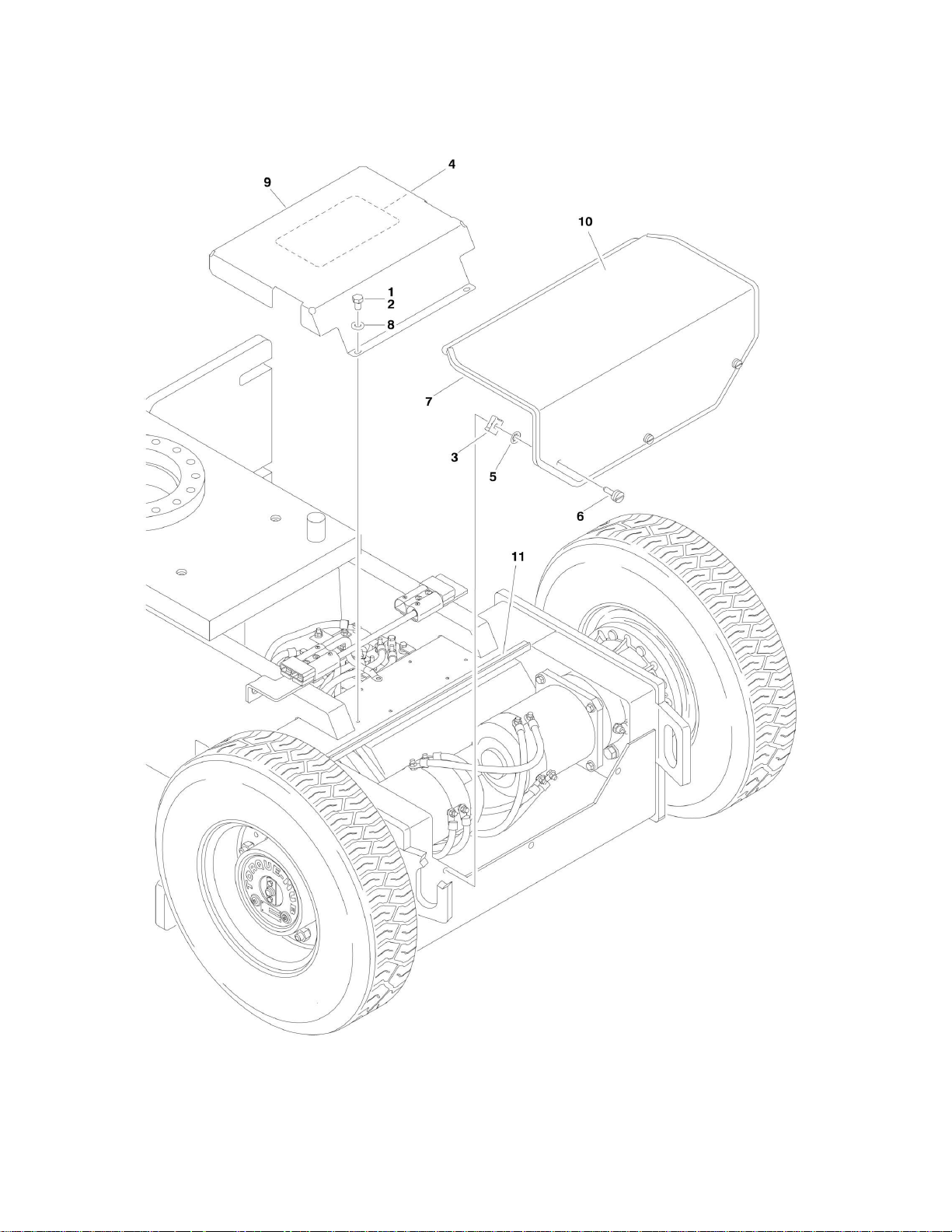
FIGURE 1-7. FRAME COVERS INSTALLATION
26 E300AJ/E300AJP 3121254

FIGURE 1-7. FRAME COVERS INSTALLATION
ITEM
PART NUMBER
QTY
DESCRIPTION
REV
1001109383
Ref
FRAME COVERS INSTALLATION
C 1 0100011
AR
Compound, Locking
2 0641504
2
Bolt 5/16in-18NC x 1/2in
3 1380138
3
Nut, Clip
4 1704246
1
Decal - Cable Routing
5 3760308
3
Retainer
6 1001112496
3
Thumbscrew
7 3960447
63 in/1.6m
Seal 8
4711500
2
Flatwasher 5/16in Thin
9 1001107751
1
Cover, Contactor
10
1001108251
1
Cover, Rear Axle
11
3960389
2 ft/.6m
Seal
SECTION 1 - FRAME
3121254 E300AJ/E300AJP 27
SECTION 1 - FRAME
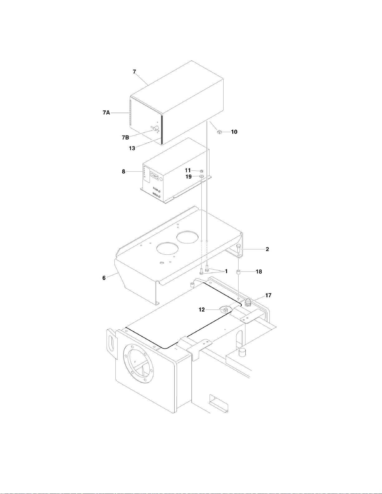
FIGURE 1-8. INVERTER INSTALLATION (OPTIONAL)
28 E300AJ/E300AJP 3121254

SECTION 1 - FRAME
ITEM
PART NUMBER
QTY
DESCRIPTION
REV
1001110271
Ref
INVERTER INSTALLATION
B 1 0641406
8
Bolt 1/4in-20NC x 3/4in
2 0641618
4
Bolt 3/8in-16NC x 2-1/4in
6 1271463
1
Channel, Mounting
7 1670953
1
Cover 7A
2600103
1
Hinge (Welded on Part)
7B
2940048
1
Latch 8
2460037
1
Inverter/Generator Assembly
10
3300353
4
Nut, Tinnerman
11
3311405
4
Locknut 1/4in-20NC
12
3311605
4
Locknut 3/8in-16NC
13
4060803
8.5
in/21cm
Flex-Trim
17
4460426
1
Connector, Strain Relief
18
4568165
4
Spacer, Tube
19
4751400
4
Flatwasher 1/4in Regular
FIGURE 1-8. INVERTER INSTALLATION (OPTIONAL)
3121254 E300AJ/E300AJP 29

 Loading...