


 Loading...
GMX 200TM
Pilot’s Guide
& Reference
© 2006-2015 Garmin Ltd. or its subsidiaries
Garmin International, Inc., 1200 East 151st Street, Olathe, KS 66062, U.S.A.
Tel: 913/397.8200 |
Fax: 913/397.8282 |
Garmin AT, Inc., 2345 Turner Road SE, Salem, OR 97302, U.S.A. |
|
Tel: 503/391.3411 |
Fax 503/364.2138 |
Garmin (Europe) Ltd., Liberty House, Bulls Copse Road, Hounsdown Business Park, Southampton, |
|
SO40 9LR, U.K. |
|
Tel. +44 (0) 87 0850 1243 |
Fax +44 (0) 23 8052 4004 |
Garmin Singapore Pte. Ltd., 46 East Coast Road, #05-06 Eastgate, Singapore 428766 |
|
Tel : (65) 63480378 |
Fax : ( 65 ) 63480278 |
Web Site Address: www.garmin.com https://fly.garmin.com/fly-garmin
All rights reserved. Except as expressly provided herein, no part of this manual may be reproduced, copied, transmitted, disseminated, downloaded or stored in any storage medium, for any purpose without the express prior written consent of Garmin. Garmin hereby grants permission to download a single copy of this manual onto a hard drive or other electronic storage medium to be viewed and to print one copy of this manual or of any revision hereto, provided that such electronic or printed copy of this manual must contain the complete text of this copyright notice and provided further that any unauthorized commercial distribution of this manual or any revision hereto is strictly prohibited.
Information in this document is subject to change without notice. Garmin reserves the right to change or improve its products and to make changes in the content without obligation to notify any person or organization of such changes or improvements. Visit the Garmin Web site (www. garmin.com) for current updates and supplemental information concerning the use and operation of this and other Garmin products.
Garmin®, GPSMAP®, AutoLocate®, TracBack®, Apollo, SafeTaxi®, FliteChart®, and MapSource® are registered trademarks of Garmin Ltd. or its subsidiaries and may not be used without the express permission of Garmin. NavData® is a trademark of Jeppesen, Inc.; SXM® is a registered trademark of Sirius XM Satellite Radio, Inc.
This part shall comply with Garmin Banned and Restricted Substances document, 001-00211-00.
March 2015 |
Part Number 190-00607-02 Rev D |
Printed in the USA |

Introduction
INTRODUCTION
History of Revisions |
|
|
Date |
Software |
Manual |
|
Version |
Revision |
May 2006 |
2.0 |
190-00607-02 Rev 1 |
June 2006 |
2.01-2.02 |
190-00607-02 Rev A |
November 2006 |
2.03 |
190-00607-02 Rev B |
July 2007 |
2.12 |
190-00607-02 Rev C |
March 2015 |
2.14 |
190-00607-02 Rev D |
Ordering Information
To receive additional copies of this GMX 200 Pilot’s Guide, order Part Number 190-00607-02. The GMX 200 Quick Reference Guide is Part Number 190-00607-03.
190-00607-02 Rev D |
i |

Introduction
End User License
End User License Agreement (“EULA”)
You have acquired a device (GMX 200) which includes software licensed by Garmin International, Inc. or its subsidiaries (Garmin) from one or more software licensors Garmin’s Software Suppliers. Such software products, as well as associated media, printed materials, and “online” or electronic documentation (“SOFTWARE”) are protected by international intellectual property laws and treaties. The SOFTWARE is licensed, not sold. All rights reserved.
•This EULA is valid and grants the end-user rights ONLY if the SOFTWARE is genuine and a genuine Certificate of Authenticity for the SOFTWARE is included. For more information on identifying whether your software is genuine, please see http://www.microsoft.com/piracy/howtotell.
•IF YOU DO NOT AGREE TO THIS END USER LICENSE AGREEMENT (“EULA”), DO NOT USE THE GMX 200 OR COPY THE SOFTWARE. INSTEAD, PROMPTLY CONTACT GARMIN FOR INSTRUCTIONS ON RETURN OF THE UNUSED GMX 200) FOR A REFUND. ANY USE OF THE SOFTWARE, INCLUDING BUT NOT LIMITED TO USE ON THE GMX 200, WILL CONSTITUTE YOUR AGREEMENT TO THIS EULA (OR RATIFICATION OF ANY PREVIOUS CONSENT).
•GRANT OF SOFTWARE LICENSE. This EULA grants you the following license:
>You may use the SOFTWARE only on the GMX 200.
>Restricted Functionality. You are licensed to use the SOFTWARE to provide only the limited functionality (specific tasks or processes) for which the GMX 200 has been designed and marketed by Garmin. This license specifically prohibits any other use of the software programs or functions, or inclusion of additional software programs or functions that do not directly support the limited functionality on the GMX 200. Notwithstanding the foregoing, you may install or enable on a GMX 200, systems utilities, resource management or similar software solely for the purpose of administration, performance enhancement and/or preventive maintenance of the GMX 200.
>If you use the GMX 200 to access or utilize the services or functionality of Microsoft Windows Server products (such as Microsoft Windows Server 2003), or
use the GMX 200 to permit workstation or computing devices to access or utilize the services or functionality of Microsoft Windows Server products, you may be required to obtain a Client Access License for the GMX 200 and/or each such workstation or computing device. Please refer to the end user license agreement for your Microsoft Windows Server product for additional information.
>NOT FAULT TOLERANT. THE SOFTWARE IS NOT FAULT TOLERANT. GARMIN HAS INDEPENDENTLY DETERMINED HOW TO USE THE SOFTWARE IN THE GMX 200, AND MS HAS RELIED UPON GARMIN TO CONDUCT SUFFICIENT TESTING TO DETERMINE THAT THE SOFTWARE IS SUITABLE FOR SUCH USE.
>NO WARRANTIES FOR THE SOFTWARE. THE SOFTWARE is provided “AS IS” and with all faults. THE ENTIRE RISK AS TO SATISFACTORY QUALITY, PERFORMANCE, ACCURACY, AND EFFORT (INCLUDING LACK OF NEGLIGENCE) IS WITH YOU. ALSO, THERE IS NO WARRANTY AGAINST INTERFERENCE WITH YOUR ENJOYMENT OF THE SOFTWARE OR AGAINST INFRINGEMENT. IF YOU HAVE RECEIVED ANY WARRANTIES REGARDING THE GMX 200 OR THE SOFTWARE, THOSE WARRANTIES DO NOT ORIGINATE FROM, AND ARE NOT BINDING ON, MS.
>No Liability for Certain Damages. EXCEPT AS PROHIBITED BY LAW, MS SHALL HAVE NO LIABILITY FOR ANY INDIRECT, SPECIAL, CONSEQUENTIAL OR INCIDENTAL DAMAGES ARISING FROM OR IN CONNECTION WITH THE USE OR PERFORMANCE OF THE SOFTWARE. THIS LIMITATION SHALL APPLY EVEN IF ANY REMEDY FAILS OF ITS ESSENTIAL PURPOSE. IN NO EVENT SHALL MS BE LIABLE FOR ANY AMOUNT IN EXCESS OF U.S. TWO HUNDRED FIFTY DOLLARS (U.S.$250.00).
>Restricted Uses. The SOFTWARE is not designed or intended for use or resale in hazardous environments requiring fail-safe performance, such as in the operation of nuclear facilities, aircraft navigation or communication systems, air traffic control, or other devices or systems in which a malfunction of the SOFTWARE would result in foreseeable risk of injury or death to the operator of the device or system, or to others.
>Limitations on Reverse Engineering, Decompilation, and Disassembly. You may not reverse engineer, decompile, or disassemble the SOFTWARE, except and only to the extent that such activity is expressly permitted by applicable, law notwithstanding this limitation.
>SOFTWARE as a Component of the GMX 200 - Transfer. This license may not be shared, transferred to or used concurrently on different computers. The SOFTWARE is licensed with the GMX 200 as a single integrated product and may only be used with the GMX 200. If the SOFTWARE is not accompanied by a GMX 200, you may not use the SOFTWARE. You may permanently transfer all of your rights under this EULA only as part of a permanent sale or transfer of me GMX 200, provided you retain no copies of the SOFTWARE. If the SOFTWARE is an upgrade, any transfer must also include all prior versions of the SOFTWARE. This transfer must also include the Certificate of Authenticity label. The transfer may not be an indirect transfer, such as a consignment. Prior to the transfer, the end user receiving the SOFTWARE must agree to all the EULA terms.
>Consent to Use of Data. You agree that MS, Microsoft Corporation and their affiliates may collect and use technical information gathered in any manner as part
of product support services related to the SOFTWARE. MS, Microsoft Corporation and their affiliates may use this information solely to improve their products or to provide customized services or technologies to you. MS, Microsoft Corporation and their affiliates may disclose this information to others, but not in a form that personally identifies you.
ii |
190-00607-02 Rev D |

Introduction
End User License
>Internet Gaming/Update Features. If the SOFTWARE provides, and you choose to utilize, the Internet gaming or update features within the SOFTWARE, it is necessary to use certain computer system, hardware, and software information to implement the features. By using these features, you explicitly authorize MS,
Microsoft Corporation and/or their designated agent to use this information solely to improve their products or to provide customized services or technologies to you. MS or Microsoft Corporation may disclose this information to others, but not in a form that personally identifies you.
>Internet-Based Services Components. The SOFTWARE may contain components that enable and facilitate the use of certain Internet -based services. You acknowledge and agree that MS, Microsoft Corporation or their affiliates may automatically check the version of the SOFTWARE and/or its components that you are utilizing and may provide upgrades or supplements to the SOFTWARE that may be automatically downloaded to your GMX 200. Microsoft Corporation or their
affiliates do not use these features to collect any information that will be used to identify you or contact you. For more information about these features, please see the privacy statement at http://go.imcrosoft.com/fwlmk/?LinkId=25243.
>Links to Third Party Sites. You may link to third party sites through the use of the SOFTWARE. The third party sites are not under the control of MS or Microsoft Corporation, and MS or Microsoft are not responsible for the contents of any third party sites, any links contained in third party sites, or any changes or updates to third party sites, MS or Microsoft Corporation is not responsible for webcasting or any other form of transmission received from any third party sites. MS or Microsoft Corporation are providing these links to third party sites to you only as a convenience, and the inclusion of any link does not imply an endorsement by MS or Microsoft Corporation of the third party site.
>Notice Regarding Security. To help protect against breaches of security and malicious software, periodically back up your data and system information, use security features such as firewalls, and install and use security updates.
>No Rental/Commercial Hosting. You may not rent, lease, lend or provide commercial hosting services with the SOFTWARE to others.
>Separation of Components. The SOFTWARE is licensed as a single product. Its component parts may not be separated for use on more than one computer.
>Additional Software/Services. This EULA applies to updates, supplements, add-on components, product support services, or Internet-based services components (“Supplemental Components”), of the SOFTWARE that you may obtain from Garmin, MS, Microsoft Corporation or their subsidiaries after the date you obtain your initial copy of the SOFTWARE, unless you accept updated terms or another agreement governs. If other terms are not provided along with such Supplemental Components and the Supplemental Components are provided to you by MS, Microsoft Corporation or their subsidiaries then you will be licensed by such entity under the same terms and conditions of this EULA, except that (i) MS, Microsoft Corporation or their subsidiaries providing the Supplemental Components will be the licensor with respect to such Supplemental Components in lieu of Garmin for the purposes of the EULA, and (ii) TO THE MAXIMUM EXTENT PERMITTED BY APPLICABLE LAW. THE SUPPLEMENTAL COMPONENTS AND ANY (IF ANY) SUPPORT SERVICES RELATED TO THE SUPPLEMENTAL COMPONENTS ARE PROVIDED AS IS AND WITH ALL FAULTS. ALL OTHER DISCLAIMERS, LIMITATION OF DAMAGES, AND SPECIAL PROVISIONS PROVIDED BELOW AND/OR OTHERWISE WITH THE SOFTWARE SHALL APPLY TO SUCH SUPPLEMENTAL COMPONENTS. MS, Microsoft Corporation or their subsidiaries reserve the right to discontinue any Internet-based services provided to you or made available to you through the use of the SOFTWARE.
>Recovery Media. If SOFTWARE is provided by Garmin on separate media and labeled “Recovery Media” you may use the Recovery Media solely to restore or reinstall the SOFTWARE originally installed on the GMX 200.
>Backup Copy. You may make one (1) backup copy of the SOFTWARE. You may use this backup copy solely for your archival purposes and to reinstall the SOFTWARE on the GMX 200. Except as expressly provided in this EULA or by local law, you may not otherwise make copies of the SOFTWARE, including the printed materials accompanying the SOFTWARE. You may not loan, rent, lend or otherwise transfer the backup copy to another user.
>End User Proof of License. If you acquired the SOFTWARE on a GMX 200, or on a compact disc or other media, a genuine Microsoft “Proof of License’”/Certificate of Authenticity label with a genuine copy of the SOFTWARE identifies a licensed copy of the SOFTWARE. To be valid, the label must be affixed to the GMX 200, or appear on Garmin’s software packaging. If you receive the label separately other than from Garmin, it is invalid. You should keep the label on the GMX 200 or packaging to prove that you are licensed to use the SOFTWARE.
>Product Support. Product support for the SOFTWARE is not provided by MS, Microsoft Corporation, or their affiliates or subsidiaries. For product support, please refer to Garmin’s support number provided in the documentation for the GMX 200. Should you have any questions concerning this EULA or if you desire to contact Garmin for any other reason, please refer to the address provided in the documentation for the GMX 200.
>Termination. Without prejudice to any other rights, Garmin may terminate this EULA if you fail to comply with the terms and conditions of this EULA. In such event, you must destroy all copies of the SOFTWARE and all of its component parts.
>EXPORT RESTRICTIONS. You acknowledge that SOFTWARE is subject to U.S. and European Union export jurisdiction. You agree to comply with all applicable international and national laws that apply to the SOFTWARE, including, the U.S. Export Administration Regulations, as well as end-user, end-use and destination restrictions issued by U.S. and other governments. For additional information see http://www.microsoft.com/exporting/ .
190-00607-02 Rev D |
iii |
Introduction
Accessories, Packing List, & Welcome
Accessories and Packing List
To obtain accessories for your GMX 200 please contact your Garmin dealer.
Help us better support you by completing our on-line registration form today! Registration ensures that you will be notified of product updates and new products and
provides lost or stolen unit tracking. Please, have the serial number of your GMX 200 handy, connect to our web site (www.garmin.com) and look for our Product Registration link on the home page.
NOTE: The GMX 200 display lens is coated with a special anti-reflective coating which is very sensitive to skin oils, waxes, and abrasive cleaners. It is very important to clean the lens using an eyeglass cleaner that is specified as safe for anti-reflective coatings and a clean, lint-free cloth.
Welcome…
Welcome to a new era of aviation navigation. Once again, Garmin has set new standards in features and ease of use for the general aviation public. The GMX 200 Multi-Function Display provides a focal point for integrating many of your navigation needs in an easy to use and convenient package.
The GMX 200 presents a wealth of information on its six-inch diagonal, 640x480 pixel, color display. The many features are organized as distinct functions.
Each function allows varying degrees of customization. The custom map function is customizable so you
can create a display for almost any configuration you require. The other functions provide more limited levels of customization.
The GMX 200 is capable of creating powerful overlay views where information from a variety of sources can be presented simultaneously in proper relationship to each other, thus greatly increasing situational awareness for the pilot.
You can be confident in knowing that you are the owner of the state-of-the-art in aviation and navigation. The GMX 200 architecture is designed to
support full expansion for both software and hardware enhancements. This flexibility protects your investment and allows for the ease of adding new features. Our products are built to last and to allow the flexibility to meet your needs as they change in the future.
iv |
190-00607-02 Rev D |

About This Manual
This manual may be used as a summary, a reference, and a learning tool. Information is provided about all of the functions available to the GMX 200. Your specific installation may not include all of these functions.
Take a few moments to familiarize yourself with the various sections in this manual. The Getting Started section gives an introduction to the controls, basic operation, and organization of the functions in your GMX 200. Be sure to read the Getting Started section to learn the rules for using the GMX 200. The Detailed Operation section (starting on page 15) is the reference for each of the functions in the GMX 200. Refer to the Detailed Operation section when you want to get into the details on every function and option along with step-by-step instructions.
Not every function is available in every installation.
Limitations
The Traffic function is not a collision avoidance system. It is an aid to visual acquisition and does not relieve the flight crew of their responsibility to “see and avoid.” There are no evasive aircraft maneuvers authorized, recommended, or provided for as a result of displayed traffic targets. Refer to the traffic sensor documentation for additional information.
All pilots/operators are reminded that the airborne equipment that displays other ADS-B equipped aircraft and transponder equipped aircraft via TIS-B is for pilot situational awareness and is not approved as a collision avoidance tool. Any deviation from an air traffic control clearance based on cockpit information must be approved by the controlling ATC facility prior to
Introduction
Limitations
commencing the maneuver. Uncoordinated deviations may place an aircraft in close proximity to other aircraft under ATC control not seen on the airborne equipment and may possibly result in the issuance of a pilot deviation.
The Terrain function shows you the general terrain elevations relative to your altitude and are advisory in nature. Individual obstructions may be shown
if available in the database. Terrain is displayed from database information and may therefore contain errors. The Terrain function does not relieve the flight crew of their responsibility to “see and avoid.” Do not use this information for navigation.
The moving map, weather information, and other displayed information are meant to be aids to situational awareness. The pilot should rely on the appropriate primary means of navigation and consult official and approved data sources prior to and during each flight.
Refer to your airplane flight manual supplement for more information.
190-00607-02 Rev D |
v |

Introduction |
|
Table of Contents |
|
Table of Contents |
|
Introduction.............................................................. |
i |
History of Revisions................................................................. |
i |
Ordering Information.............................................................. |
i |
End User License Agreement (“EULA”) ................................... |
ii |
Accessories and Packing List................................................... |
iv |
Welcome…............................................................................iv |
|
About This Manual................................................................. |
v |
Limitations.............................................................................. |
v |
Getting Started........................................................ |
1 |
Functions............................................................................... |
1 |
GMX 200 Function List..................................................... |
1 |
Display................................................................................... |
3 |
Message Flag................................................................... |
3 |
Controls................................................................................. |
4 |
Power On ........................................................................ |
4 |
Power.............................................................................. |
4 |
Brightness........................................................................ |
4 |
Rotary Knob..................................................................... |
4 |
Function (FN) Key............................................................. |
4 |
MENU/ENT....................................................................... |
5 |
Menu Item....................................................................... |
5 |
Data Card.............................................................................. |
5 |
Annunciations........................................................................ |
6 |
Advisory Flags.................................................................. |
6 |
ADS-B Traffic.................................................................... |
6 |
TAS/TCAD/TIS-A Traffic..................................................... |
6 |
Radar............................................................................... |
6 |
Terrain.............................................................................. |
6 |
Lightning......................................................................... |
6 |
ADS-B Status Annunciation.............................................. |
6 |
Basic Operation...................................................................... |
8 |
Start Up Screen...................................................................... |
8 |
Confirm Current Baro Correction........................................... |
9 |
Function Selection.................................................................. |
9 |
Advisory Hot Key................................................................. |
10 |
Normal Cruise Condition................................................ |
10 |
Viewing the Advisory..................................................... |
10 |
Returning To Normal Condition...................................... |
10 |
Alert Hot Key....................................................................... |
10 |
Options Menu...................................................................... |
10 |
Thumbnail Feature............................................................... |
11 |
Traffic on Thumbnail...................................................... |
11 |
Terrain on the Thumbnail............................................... |
11 |
Obstructions on the Thumbnail...................................... |
11 |
Thumbnail Activation..................................................... |
11 |
Traffic Information Services (TIS)........................................... |
12 |
Polar Navigation................................................................... |
12 |
Detailed Operation................................................ |
15 |
Message Log (MSG) ..................................................................... |
15 |
Custom Map (MAP)....................................................................... |
16 |
Initial Zoom Level................................................................. |
16 |
Map Scale............................................................................ |
16 |
Auto Zoom.......................................................................... |
16 |
Pan ..................................................................................... |
17 |
Info ..................................................................................... |
17 |
Info In Pan Mode................................................................. |
17 |
Custom Map Menu Option Page 1....................................... |
18 |
Flight Plan............................................................................ |
18 |
Map Orientation.................................................................. |
18 |
Invert................................................................................... |
18 |
Nav Data.............................................................................. |
18 |
Load Chart (Optional).......................................................... |
19 |
Custom Map Menu Option Page 2....................................... |
19 |
Airports.......................................................................... |
19 |
Hot Spots....................................................................... |
20 |
VORs................................................................................... |
21 |
VOR Highlight................................................................ |
21 |
VOR OBS............................................................................. |
21 |
ILS/Localizer Depiction ................................................... |
22 |
Localizer Back Course Display ........................................ |
22 |
NDBs .................................................................................. |
22 |
Intersections........................................................................ |
22 |
Airspace............................................................................... |
22 |
Custom Map Menu Option Page 3....................................... |
23 |
Low Airways........................................................................ |
23 |
High Airways....................................................................... |
23 |
Water.................................................................................. |
23 |
Roads.................................................................................. |
23 |
Cities................................................................................... |
23 |
Custom Map Menu Option Page 4....................................... |
24 |
Boundaries........................................................................... |
24 |
Nexrad................................................................................. |
24 |
METARs............................................................................... |
24 |
Lightning............................................................................. |
24 |
Cell Move............................................................................ |
24 |
Custom Map Menu Option Page 5....................................... |
24 |
Airport Chart (ChartView).................................................... |
25 |
Terrain................................................................................. |
25 |
Obstructions........................................................................ |
26 |
Traffic.................................................................................. |
26 |
Strikes ................................................................................. |
26 |
IFR En Route (IFR) Chart Function................................................. |
27 |
SafeTaxi............................................................................... |
27 |
vi |
190-00607-02 Rev D |

Hot Spots............................................................................. |
27 |
IFR Option Page 1................................................................ |
28 |
Flight Plan............................................................................ |
28 |
Map Orientation.................................................................. |
28 |
Invert................................................................................... |
28 |
Nav Data.............................................................................. |
28 |
Label.................................................................................... |
29 |
IFR Option Page 2................................................................ |
29 |
Low Airways........................................................................ |
29 |
High Airways....................................................................... |
29 |
Airport Chart (Jepp ChartView)............................................ |
29 |
Load Chart........................................................................... |
30 |
VFR Chart (VFR) Function.............................................................. |
31 |
SafeTaxi............................................................................... |
31 |
Hot Spots............................................................................. |
31 |
Flight Plan............................................................................ |
32 |
Map Orientation.................................................................. |
32 |
Invert................................................................................... |
32 |
Nav Data.............................................................................. |
32 |
Label.................................................................................... |
32 |
Split Screen (SPLIT) Function........................................................ |
33 |
TAS / TCAD Traffic (TRAF) Function ............................................... |
34 |
Traffic Depiction................................................................... |
34 |
Symbology........................................................................... |
34 |
Alert Hot Key....................................................................... |
34 |
Traffic Alert Pop-Up............................................................. |
34 |
Vert Smart Key (TAS)............................................................ |
35 |
Traffic Status Indicators........................................................ |
35 |
Off Scale........................................................................ |
35 |
Standby (TAS)................................................................. |
35 |
Test (TAS)....................................................................... |
35 |
Not Displayed................................................................. |
35 |
TAS Fail.......................................................................... |
35 |
TAS Data Fail.................................................................. |
35 |
TAS Data Time-Out........................................................ |
35 |
No Bearing Advisories.......................................................... |
35 |
TAS Menu Options............................................................... |
35 |
Traffic Alert Mode (Pop-Up/Prompt)................................ |
35 |
Standby Mode............................................................... |
35 |
Self-Test......................................................................... |
35 |
TCAD 9900B Menu Options................................................. |
36 |
Altitude Option (Relative/Pressure).................................. |
36 |
Filter.............................................................................. |
36 |
Volume.......................................................................... |
36 |
Approach Mode............................................................. |
36 |
Mute Duration............................................................... |
36 |
Shield............................................................................. |
36 |
Shield Heights................................................................ |
36 |
Introduction |
|
Table of Contents |
|
Shield Ranges................................................................. |
36 |
TCAD 9900BX Menu Options.............................................. |
36 |
Altitude Option (Relative/Pressure).................................. |
36 |
Filter.............................................................................. |
36 |
Volume.......................................................................... |
36 |
Approach Mode............................................................. |
36 |
Ground/Flight Mode....................................................... |
36 |
ADS-B Traffic (TRAF) Function ...................................................... |
37 |
Traffic Description................................................................ |
38 |
TIS-B Traffic.................................................................... |
39 |
TIS-B Limitations............................................................. |
40 |
Degraded Target............................................................ |
41 |
Target Color................................................................... |
41 |
Surface Targets .............................................................. |
41 |
Traffic Altitude Values..................................................... |
41 |
Ident.............................................................................. |
41 |
Operation...................................................................... |
41 |
Traffic Option Page 1........................................................... |
42 |
Transmit Status ................................................................... |
42 |
ADS-B Broadcast Mode Control........................................... |
42 |
Broadcast FID................................................................. |
42 |
Broadcast VFR................................................................ |
42 |
Enter Code (ADS-B Air Traffic Source)................................... |
42 |
Set 1200.............................................................................. |
43 |
Services................................................................................ |
43 |
Traffic Menu Option Page 2................................................. |
43 |
Time.................................................................................... |
43 |
Traffic Altitude Filter............................................................. |
43 |
Altitude Option (Relative/Absolute) .................................... |
44 |
Flight Plan............................................................................ |
44 |
Traffic Map Orientation ....................................................... |
44 |
Traffic Menu Option Page 3................................................. |
44 |
Display Mode....................................................................... |
44 |
Graphic Display.............................................................. |
44 |
Text Display.................................................................... |
44 |
Enter FID.............................................................................. |
45 |
Label.................................................................................... |
45 |
TIS-A Traffic (TRAF) Function ........................................................ |
45 |
Traffic Depiction................................................................... |
46 |
TIS-A Menu Options............................................................. |
46 |
Alert Hot Key (TA Prompt) ............................................. |
46 |
Traffic Alert Pop-Up (TA Popup)...................................... |
46 |
Operate/Standby ........................................................... |
47 |
Symbology........................................................................... |
47 |
Traffic Status Indicators........................................................ |
47 |
Flight Plan (FPL) Function............................................................. |
48 |
METARs............................................................................... |
48 |
Terrain (TER) Function................................................................... |
50 |
190-00607-02 Rev D |
vii |

Introduction |
|
Table of Contents |
|
Internal GMX 200-Based Terrain.......................................... |
50 |
Obstructions........................................................................ |
50 |
Terrain Option Page............................................................. |
51 |
Flight Plan............................................................................ |
51 |
TRK Up Arc/TRK Up 360....................................................... |
51 |
Set Barometer (Pressure Altitude only).................................. |
51 |
TER Data Flag....................................................................... |
52 |
External TAWS-Based Terrain Display.................................... |
52 |
TAWS Pop-Up Modes........................................................... |
52 |
UAT Flight Information Service (FIS) Function ............................. |
53 |
Text Display.......................................................................... |
54 |
Viewing Text.................................................................. |
54 |
Clearing Text FIS Messages............................................. |
54 |
Sorting Text FIS Messages............................................... |
54 |
GDL 69/69A Flight Information Service (FIS) Function ................ |
55 |
Weather Product Zoom Scale............................................... |
55 |
Temporary Flight Restrictions (TFRs)...................................... |
55 |
NEXRAD Description............................................................ |
56 |
NEXRAD Abnormalities.................................................. |
56 |
NEXRAD Limitations....................................................... |
56 |
NEXRAD Intensity........................................................... |
56 |
Current................................................................................ |
57 |
NEXRAD......................................................................... |
57 |
METARs.......................................................................... |
58 |
Lightning....................................................................... |
58 |
Cell Movement.............................................................. |
58 |
Cloud Tops..................................................................... |
59 |
Echo Tops....................................................................... |
60 |
Winds Aloft.................................................................... |
60 |
Winds Aloft Altitude...................................................... |
60 |
TFR Label....................................................................... |
61 |
GDL 69/69A FIS Current Menu Page 3............................ |
61 |
Label.............................................................................. |
61 |
Flight Plan...................................................................... |
61 |
Legend........................................................................... |
61 |
Map Detail..................................................................... |
62 |
Map Orientation............................................................ |
62 |
Product Times................................................................ |
63 |
Forecast............................................................................... |
63 |
Surface Analysis............................................................. |
64 |
City................................................................................ |
65 |
Forecast Time................................................................. |
65 |
SIGMET.......................................................................... |
65 |
AIRMET.......................................................................... |
65 |
GDL 69/69A FIS Forecast Menu Page 2........................... |
66 |
Freezing Levels............................................................... |
66 |
County........................................................................... |
66 |
Cyclone.......................................................................... |
66 |
TFR Label....................................................................... |
66 |
Label.............................................................................. |
66 |
GDL 69/69A FIS Forecast Menu Page 3........................... |
67 |
Flight Plan...................................................................... |
67 |
Legend........................................................................... |
67 |
Map Detail..................................................................... |
67 |
Map Orientation............................................................ |
67 |
Text...................................................................................... |
68 |
Selecting Categories and Messages................................ |
68 |
Sorting METAR, TAF, and TFR Text Messages................... |
69 |
View.............................................................................. |
69 |
Temporary Flight Restrictions (TFRs)................................ |
69 |
Status.................................................................................. |
70 |
Product Status................................................................ |
70 |
Diagnostics.................................................................... |
70 |
Activation...................................................................... |
71 |
Activating XM Radio Services............................................... |
71 |
Gather Information........................................................ |
71 |
XM Satellite Radio Activation ........................................ |
72 |
Lightning Strikes (LT) Function...................................................... |
73 |
Lightning Menu Page 1........................................................ |
73 |
Flight Plan............................................................................ |
73 |
Display View (360/120)........................................................ |
73 |
Lightning............................................................................. |
73 |
Strike............................................................................. |
73 |
Cell................................................................................ |
74 |
Heading Stabilization........................................................... |
74 |
System Data......................................................................... |
74 |
Lightning Menu Page 2........................................................ |
74 |
Demo.................................................................................. |
74 |
Self-Test............................................................................... |
74 |
Noise Monitor...................................................................... |
75 |
Strike Test............................................................................ |
75 |
Antenna Change Message................................................... |
75 |
FliteChart (CHART) Function......................................................... |
76 |
Data Card...................................................................... |
76 |
FliteChart Function............................................................... |
76 |
Menu Items......................................................................... |
78 |
Search ID........................................................................ |
78 |
Select Airport................................................................. |
79 |
Select Chart................................................................... |
79 |
ChartView (CHART) Function (Optional)....................................... |
80 |
Overview............................................................................. |
80 |
Chart Data Source............................................................... |
81 |
Data Card...................................................................... |
81 |
Chart Geo-Referencing .................................................. |
81 |
Hot Spots....................................................................... |
81 |
Chart Overlay in the Custom/IFR Map.................................. |
81 |
viii |
190-00607-02 Rev D |
Selecting the Airport...................................................... |
81 |
Loading the Approach Chart.......................................... |
82 |
Viewing the Chart as an Overlay.......................................... |
83 |
Display of Coverage Area............................................... |
83 |
Chart Zooming............................................................... |
83 |
Chart Panning................................................................ |
83 |
Chart Orientation........................................................... |
83 |
Chart Info...................................................................... |
83 |
ChartView Function............................................................. |
84 |
Menu Items......................................................................... |
85 |
Search ID........................................................................ |
85 |
Select Airport................................................................. |
86 |
Select Chart................................................................... |
86 |
View Loaded.................................................................. |
86 |
Load to Map.................................................................. |
86 |
Airport Surface Charts......................................................... |
87 |
Viewing Surface Charts.................................................. |
87 |
Operational Considerations.................................................. |
88 |
When to Load a Chart.................................................... |
88 |
Flying an Approach........................................................ |
88 |
Approach to Surface Map Transitions............................. |
88 |
Chart NOTAMS.............................................................. |
88 |
Important System Limitations......................................... |
88 |
Invert Option.................................................................. |
88 |
Hot Spots....................................................................... |
88 |
Typical Operational Scenario................................................. |
89 |
Typical Taxi Scenario....................................................... |
89 |
Typical Take Off Scenario................................................ |
89 |
Typical Approach Scenario.............................................. |
89 |
Typical Landing Scenario................................................. |
89 |
Radar (RADAR) Function............................................................... |
90 |
Off Mode....................................................................... |
90 |
Standby/On Mode ......................................................... |
90 |
Test Mode ..................................................................... |
91 |
Weather Mode .............................................................. |
91 |
MAP Mode.................................................................... |
91 |
Manual Gain (GWX 68 only).......................................... |
91 |
Horizontal Mode............................................................ |
92 |
Vertical Mode (GWX 68 and ART2000/2100 only).......... |
92 |
Range Control................................................................ |
92 |
Tilt Control..................................................................... |
92 |
Bearing Control (GWX 68/ART2000/2100 only).............. |
92 |
Gain Control.................................................................. |
93 |
Hold Control.................................................................. |
93 |
Cursor Pre-Select Operation (GWX 68 and ART2000/2100 only) |
|
...................................................................................... |
93 |
Sector Scan (GWX 68 only)............................................ |
94 |
Radar Alert (GWX 68 only)............................................. |
94 |
Introduction |
|
Table of Contents |
|
Radar Setup Page................................................................. |
94 |
Stabilization (STAB)......................................................... |
94 |
Target Alert (GWX 68 only)............................................ |
94 |
Garmin GWX 68 Radar Description...................................... |
97 |
Principles of Pulsed Airborne Weather Radar.................. |
97 |
Radar Signal Attenuation............................................... |
98 |
Radar Signal Reflectivity....................................................... |
99 |
Precipitation................................................................... |
99 |
Ground Returns............................................................. |
99 |
Angle of Incidence....................................................... |
100 |
Operating DISTANCE.......................................................... |
100 |
MAXIMUM PERMISSIBLE EXPOSURE LEVEL (MPEL)............. |
100 |
Antenna Tilt Setup at Cruise Altitude................................. |
101 |
Weather Mapping and Interpretation................................. |
102 |
Weather display Interpretation..................................... |
102 |
Thunderstorms............................................................. |
102 |
Tornadoes.................................................................... |
104 |
Hail.............................................................................. |
104 |
SiriusXM Satellite Radio (XM) Function...................................... |
105 |
Menu Page 1..................................................................... |
106 |
Radio ID....................................................................... |
106 |
Save Preset................................................................... |
107 |
Last Channel................................................................ |
107 |
Menu Pages 2-4................................................................. |
107 |
Volume.............................................................................. |
108 |
Mute............................................................................ |
108 |
Channels........................................................................... |
108 |
Categories......................................................................... |
109 |
Direct Access..................................................................... |
109 |
Activating SiriusXM Satellite Radio Services........................ |
110 |
Gather Information...................................................... |
110 |
SiriusXM Advisory Messages.............................................. |
111 |
System (SYS) Function................................................................. |
112 |
System Nav Pages.............................................................. |
112 |
Ownship Symbol ......................................................... |
112 |
Lat/Lon Format............................................................. |
112 |
Set Baro Correction Units (Pressure Altitude Source only)112 |
|
Set Baro Correction (Pressure Altitude Source only)....... |
112 |
Display Latitude/Longitude Lines .................................. |
112 |
Initial En Route Zoom Scale, Initial Ground Zoom Scale, and |
|
Transition Speed..................................................... |
113 |
Slave Zoom to GPS Zoom............................................. |
113 |
AutoLoad Electronic Charts.......................................... |
114 |
Altitude Units............................................................... |
114 |
Map Detail................................................................... |
114 |
System Info Pages.............................................................. |
114 |
System Information...................................................... |
114 |
Feature Information...................................................... |
115 |
190-00607-02 Rev D |
ix |

Introduction |
|
Hardware Information.................................................. |
115 |
Port Status................................................................... |
115 |
Data Link Status .......................................................... |
115 |
System Test Pages.............................................................. |
115 |
Test Pattern 1............................................................... |
116 |
Red, Green, Blue, White, and Black Test Patterns.......... |
116 |
Test Pattern 2............................................................... |
116 |
Troubleshooting.......................................................................... |
117 |
GDL 69/69A FIS Legends............................................................. |
119 |
Sample GDL 69/69A FIS Displays................................................ |
120 |
Specifications.............................................................................. |
121 |
Physical Specifications........................................................ |
121 |
Power................................................................................ |
121 |
Environmental.................................................................... |
121 |
Care Information......................................................................... |
121 |
Cleaning the Unit............................................................... |
121 |
Contacting the Factory....................................................... |
121 |
GMX 200 Safety Monitor Codes................................................. |
122 |
Operational Response........................................................ |
122 |
Pre-Flight and Post-Flight.............................................. |
122 |
During Flight................................................................ |
122 |
Glossary...................................................................................... |
123 |
Abbreviations.............................................................................. |
124 |
License and Registration Information......................................... |
127 |
Contacting the Factory ............................................................... |
127 |
Software License Agreement.............................................. |
127 |
Product Registration and Support....................................... |
127 |
Limited Warranty......................................................................... |
128 |
Index........................................................................................... |
129 |
x |
190-00607-02 Rev D |

GETTING STARTED
This section explains how to get started using the GMX 200. Information in this section describes the controls, data card, display, and basic operation. After reading this section, go to the Detailed Operation section for expanded explanations for each feature.
Functions
The GMX 200 contains fourteen major separate functions for the display of information. The function names are shown as “smart” keys at the bottom of the display. The “smart” key is the combination of a label above a triangle key at the bottom of the display. The labels above the triangle keys change to reflect the choices available to you for each function. Press the FN key to show the available functions. Press
the “smart” key below the function label to go to the desired function. While in each function, press the MENU/ENT key to show the options for each function. The options are shown on the right side of the display. Press the Menu Item key to manipulate the options. Some options toggle on/off, while some are tri-state (three choices) and others cycle through a series of choices.
Getting Started
Functions
GMX 200 Function List
•MSG - Message Log
•MAP - Custom Map
•IFR - IFR Chart
•VFR - VFR Chart
•Split - Split Screen
•Traffic - TAS/TCAD/IHAS
•Traffic - ADS-B TRAF
•Traffic - TIS-A
•FPL - Flight Plan
•TER - Internal/TAWS Terrain
•FIS-B - Flight Information Service (UAT, such as GDL 90 or GDL 88)
•FIS - Flight Information Service (GDL 69/69A)
•XM - XM Satellite Radio
•LT - Lightning Strikes
•CHART - FliteChart or ChartView
•RADAR - Weather Radar
•SYS - System Information
190-00607-02 Rev D |
1 |

Getting Started
Functions
The Message Log displays information from the GMX 200 or reported to the GMX 200 by its external sensors. A flashing MSG annunciator notifies you of a new message that should be viewed.
The Custom Map function allows you to completely customize the displayed map by overlaying selected information. The Custom Map can become cluttered if you choose every option, so use discretion.
The IFR Chart function provides an IFR en route style map on the display. The VFR Chart function provides a VFR sectional style map on the display.
The Split Screen function allows up to two of the other functions to be displayed side by side and an optional vertical profile across the bottom of the display. The terrain and profile features are not available if altitude data is not available or if a TAWS sensor is connected to the GMX 200.
The Traffic function (when installed) shows nearby traffic and details about each target. The Flight Plan function provides details about your flight plan and each waypoint.
The Terrain function shows a color coded map of terrain elevation in relation to your altitude. An altitude sensor or TAWS sensor is required to provide altitude data.
The Flight Information Services (FIS) function is capable of displaying text and graphic weather information with GDL 90 UAT, GDL 88, GDL 69/69A, or other appropriate equipment installations. A subscription for the services is required with the GDL 69/69A.
The Lightning (LT) function, when connected to the L3 WX500 Stormscope, displays lightning strike information.
The Chart feature provides the capability to view Garmin FliteChart or Jeppesen Sanderson Inc. electronic charts. Garmin’s FliteChart shows approach charts. Jeppesen Sanderson’s ChartView provides approach charts and airport surface charts.
The XM function allows the reception of SiriusXM Satellite Radio entertainment broadcasts when the GDL 69A is installed and a subscription to the SiriusXM Radio service is activated.
The Radar Function allows weather radar from the Garmin GWX 68, ART2000, ART2100, RS 811A, or RS 181A to be displayed.
The System Information function lets you set general preferences, show software version information, and test the display.
2 |
190-00607-02 Rev D |
Getting Started
Controls
Display
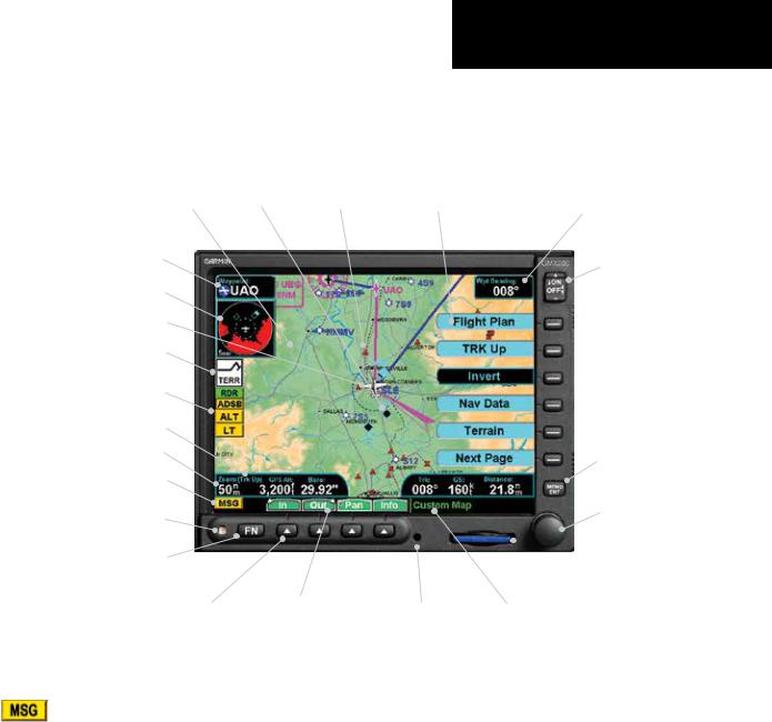
The GMX 200 display provides text and graphic information to give a “picture” of your flight and surroundings. The display brightness may be set manually or allowed to automatically adjust to ambient light conditions. At the bottom of the display, labels above the function keys change to show the different choices for each function to allow access to commonly used actions. A typical Custom Map function display is shown below.
Graphic Display
TO Waypoint Identifier
Traffic & Terrain Thumbnail
Ownship
Advisory Flags
Data Flags
Map Orientation
Zoom (Map Scale)
Message Flag
Photosensor
Function Key
“Smart” (Function) Keys
Traffic Obstruction
“Smart” (Function) Key Labels
Menu Item Labels |
Bearing to Destination |
|
(TO) Wpt |
|
Power/Dimming |
|
Menu Item Keys |
Menu/Enter Key
Rotary Knob and
Push Button
 Data Card
Mounting Screw |
Currently Selected Function |
Message Flag
The Message flag will appear on the lower left side of the display when a new message is posted. Go to the Message function to view the information about the operation or status of the GMX 200.
190-00607-02 Rev D |
3 |
Getting Started
Data Card
Controls
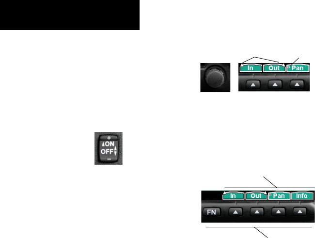
Power On
The power switch is located in the upper right corner of the GMX 200. Press the “+” rocker switch to turn the power on. The GMX 200 will progress through a series of startup screens. The final startup screen shows System Information and the results of the Self-Test.
Power
The power and display brightness are controlled by a rocker switch.
Power Rocker Switch
Press both the “-” and “+” rocker switches and hold them down for at least three seconds to turn the power off.
Brightness
Press the “-” and “+” rocker switches individually to adjust the display brightness manually. Press the “-” and “+” rocker switches at the same time for one to three seconds, then release them to have the GMX 200 set the brightness automatically based on current lighting conditions.
Rotary Knob
The rotary knob on the lower right corner of the GMX 200 is used to move the cursor in Pan mode and to zoom in and out while viewing maps. The rotary knob complements the action of the function keys
in some functions by pressing and turning the knob. Arrows will appear above the function keys indicating the direction to turn the rotary knob for the same effect. A round push button symbol (“o”) will appear indicating that pressing the rotary knob will have the same effect.
|
Round push-button sym- |
|
Arrows indicate rotary |
bol indicates the function |
|
affected when the rotary |
||
knob direction |
||
knob is depressed |
||
|
Rotary Knob |
Rotary Knob / Function Keys |
Function (FN) Key
The Function keys are made up of one dedicated key on the lower left side of the display and the four “smart” keys to the right of it. Press the function (FN) key repeatedly to scroll through the available functions. The functions will appear above the “smart” function keys in turquoise.
“Smart” Function Key Labels
“Smart” Function Keys
Function Keys
Use the FN key to display a list of the main functions, such as Map, IFR, Terrain, etc. Each time you press the FN key you will step through the list of functions. After you press one of the function “smart” keys at the bottom of the display, the function keys change to provide options to control the display related to the current function, now in green. Change the function keys back to the function list by pressing the FN key.
4 |
190-00607-02 Rev D |

MENU/ENT
The MENU/ENT key is located on the bottom right corner of the GMX 200. Press the MENU/ENT key to show a menu of options to modify the display of the current function. Press the MENU/ENT key to hide the menu. If no action is taken, the menu will automatically extinguish in 20 seconds.
MENU/ENT Key
Menu Item
The Menu Item keys are on the right side of the GMX 200. Press the MENU/ENT key to see the options for the current function. Press the Menu Item key next to each option to scroll through the choices for each option. Some options support tri-state or multiple choices, such as in Map mode. When you select a tristate option, the option label will change with each key press between filled cyan (active), filled white (intermediate), and black (inactive).
Menu
Item
Keys
Menu
Item
Labels
Menu Item Key Layout
Getting Started
Display
Data Card
The Map databases and other information are stored on a data card. The use of a data card allows you to easily update information.
Only change the data card when the power is turned off.
Only Garmin-approved datacards can be used.
Data Card and Slot
Handle your data card carefully. Do not touch the connector edge of the data card. To eject the card, press the card in until it “clicks” and then pull the card straight out of the slot. Insert a data card by pushing the card straight into the slot until it “clicks.” When fully inserted, the data card will be flush and slightly recessed into the bezel.
When contacting your dealer or the Garmin customer service department, eject the data card and write down the information shown on the label.
190-00607-02 Rev D |
5 |
Getting Started
Annunciations
Annunciations
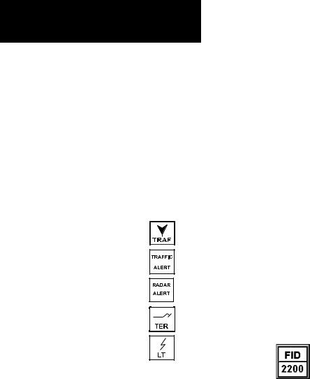
Advisory flags, data flags, and messages appear on the display to give information about the status of the GMX 200 or to provide operating information.
Advisory Flags
Annunciations will appear on the upper left side of the display to provide advisories for Traffic, Terrain, and Lightning. Advisory information is monitored and displayed regardless of the selected function. Advisory flags will flash for approximately 10 seconds when they first appear and then turn solid while they are still valid. Advisory icons will reduce in size if more than two advisory conditions exist.
Advisory Flags
ADS-B Traffic
The Traffic advisory flag will appear on the left side of the display when the UAT reports a traffic alert. This Traffic advisory is only available when the ADS-B system with a UAT data link is installed and operational. Refer to the TIS Traffic section for a description of TIS-A and TIS-B. The flag will also appear if GPS data is not available.
TAS/TCAD/TIS-A Traffic
The Traffic Advisory/Alert will appear in amber on the left side of the display when the traffic sensor indicates an alerting condition. Refer to the TIS Traffic section for a description of TIS-A and TIS-B. The flag will also appear if GPS data is not available.
Radar
The Radar Alert flag will appear when Target Alerts are present on two consecutive sweeps within 10° of your heading.
Terrain
The Terrain advisory flag will appear on the left side of the display when the terrain surface or obstacle altitude is within approximately 100 feet of your altitude and within approximately two minutes of flight in any direction.
Lightning
The Lightning advisory flag will show on the left side of the display when the WX500 sends an indication that lightning has been detected within 50 NM of your location. See the WX500 manual for details about range and other capabilities.
Data Flags
Data flags appear on the left side of the display to notify you when there is a loss of reported information. The data usually displayed, such as lightning or nearby terrain, may still exist, but may not be displayed for technical reasons. For instance, when the amber TRAF data flag appears it means that the GMX 200 is not receiving Traffic information from the sensor. Any
existing traffic will not be displayed on the GMX 200. All data flags are yellow unless otherwise indicated.
ADS-B Status Annunciation
When the GMX 200 Code Edit option is enabled, an annunciation will appear in the top left portion of the display to indicate the Flight ID broadcast status and the current ADS-B code.
The top half will indicate the operation being used: Broadcast FID (FID), Broadcast VFR (VFR), or Stand-By (STBY). The bottom half will show the transponder code that is being used. When an ADS-B code has not been selected, the code in the bottom half will be replaced by dashes.
6 |
190-00607-02 Rev D |

|
|
Getting Started |
|
|
|
Annunciations |
|
|
|
|
|
|
|
|
|
Data Flag |
Description |
|
|
|
No valid position information is available from the source. Do not expect a valid position |
||
|
representation on the maps. |
|
|
|
No valid route (flight plan) is available from the external navigation source. Route (flight |
||
|
plan) information will not be shown on the maps. |
|
|
|
No valid altitude information is available from the external source. Altitude related func- |
||
|
tions will not operate, such as terrain awareness. |
|
|
|
No traffic information is received from the optional traffic sensor. Traffic will not be |
||
|
displayed. |
|
|
|
The GPS receiver in the UAT is not reporting a valid position. ADS-B broadcast will not |
||
|
include a valid position report. |
|
|
|
No valid lightning detection information is being received from the optional Stormscope |
||
|
sensor. Strike and cell information will not be displayed. |
|
|
|
Terrain coverage is not available for some part of the terrain advisory coverage area. |
||
|
Terrain advisories may not be provided. |
|
|
|
When connected to the SL30, indicates the SL30 is not available or valid. ILS, OBS, and |
||
|
VORs will not be highlighted. |
|
|
|
Indicates that radar status information is not available from the optional external radar |
||
|
transmitter head. Radar related functionality may not be available. |
|
|
|
Indicates that the radar is ON and transmitting RF energy. Appropriate precautions |
||
(Green) |
should be taken. |
||
|
|
|
|
|
Indicates that the radar is in Hold and is transmitting RF energy. Appropriate precau- |
||
(Green Flashing) |
tions should be taken. |
|
|
|
Displayed when the UAT is in Ident mode. |
||
(Green) |
|
|
|
|
No valid terrain information is available from the optional external source. |
||
|
|
|
|
|
No valid data link information is available from the optional external source. |
||
|
|
|
|
All data flags are yellow, except as noted.
190-00607-02 Rev D |
7 |

Getting Started
Data Flags
Basic Operation
Use the following items to get a basic feel for the operation of the GMX 200. The basic steps for using any of the separate functions of the GMX 200 are:
•Turn the power on.
•Adjust the brightness or leave in automatic mode.
•Check that all tests pass on the Start Up screen.
•Press the FN key to view available functions. Each press of the FN key will step through the lists of functions.
•Press the key below the function label to select the desired function.
•Confirm or enter the current barometric pressure (if prompted).
•Press the MENU/ENT key to display available options.
•Press the Menu Item key next to the displayed option to choose desired capabilities. Some options use multiple key presses for different states for the option. Press the MENU/ ENT key again to extinguish the option display.
•Refer to the Detailed Operation section for more details on each function.
Start Up Screen
The Start Up screen is displayed while the GMX 200 goes through its initialization and testing routines. System information is shown that provides the GMX 200 software, hardware, and database versions. The results of the self test are shown. A check
mark shows that the test passed. If any of the Self-Tests fail (red “x”), contact your dealer or the factory.
Start Up Screen After Passing Tests.
Hardware version will vary depending on the configuration.
8 |
190-00607-02 Rev D |
Confirm Current Baro Correction
When the altitude source is an altitude encoder, a window that displays the current barometric value will appear after you press the first “smart” key, and then every 30 minutes. This window will not appear when GPS altitude is used. You must verify the current value or enter a new value. Press + or turn the rotary knob clockwise to increase the value. Press - or turn the rotary knob counter-clockwise to decrease the value. Press OK to confirm the existing values or to accept changes you have just entered.
Barometric Pressure Confirmation
Getting Started
Start Up and Baro Correction
Function Selection
Press the FN key to view the different Functions. The functions are shown above the function “smart” keys on the lower part of the display in blue. Press the function key under the function label to activate that function. The labels above the function key will change to reflect the custom “smart” controls for that function (in green). All of the described functions may not be available in each installation.
Function |
Description |
MSG |
Message Log Function |
MAP |
Custom Map Function |
IFR |
IFR En Route Map |
VFR |
VFR Sectional Map |
SPLIT |
Split Screen (Displays Two |
|
Functions) |
TRAF |
Traffic Display |
FPL |
Flight Plan Information |
TER |
Terrain Depiction |
FIS |
Flight Information Service |
|
- Graphic and Text Weather |
XM |
XM Satellite Radio Audio |
LT |
Lightning Detection and |
|
Reporting |
CHART |
Chart (FliteChart) or |
|
Chart (ChartView) |
RADAR |
Weather Radar Function |
SYS |
System Information |
190-00607-02 Rev D |
9 |

Getting Started
Function Selection
Advisory Hot Key
The “Advisory Hot Key” feature allows advisory conditions to be quickly viewed with minimal effort by the pilot. This feature is comprised of three components:
1.A white advisory flag on the left side of the screen indicates an advisory condition. The corresponding Function label will also be highlighted in white when selecting a new Function with the FN key. This feature allows any Function with a pending advisory to be quickly recognized in the Function menu.
2.When a function is entered that has an advisory posted, the zoom level will be adjusted to show the advisory causing object (terrain for example), and the map orientation will be forced to “Track Up 360” to get a good view of what is around the aircraft.
3.When returning to the previous Function after viewing a Function with an advisory, the original zoom and map mode will be restored.
This feature is designed to allow the pilot to establish a preferred “cruise” map setup and quickly view an advisory, then return back to the previous setting. For example:
Normal Cruise Condition
Custom Map Function is being viewed at 5 NM in the ARC mode.
Terrain Advisory Occurs at 10 NM in front of aircraft: The Terrain Advisory Indicator flashes then goes steady on the left side of the display.
Viewing the Advisory
The pilot presses the FN key and sees the TER Function highlighted in white, indicating it has an advisory condition. Pressing the TER key to enter the
Terrain Function at this point will automatically adjust the zoom level to 10 NM and place the unit in full “360” mode to show overall situational awareness.
Returning To Normal Condition
After evaluating the advisory, to return to normal viewing simply select the original Function that was being viewed before the advisory was viewed. When this is done, the zoom level will be set back to 5 NM and the display mode will be returned to ARC mode.
Alert Hot Key
Traffic alerts go one step further than the Advisory hot key feature and will automatically bring up the Function Menu showing the Traffic function. This is called the “prompt” mode. A single key press can then be used to switch the display to the Traffic function. The Alert hot key feature will automatically clear when the traffic alert condition no longer exists.
Also note that a “pop-up” mode can be enabled on the Traffic function, which makes the Traffic page display when a Traffic Advisory occurs. The “prompt” or “pop-up” mode is selected in the Traffic function.
Options Menu
Most functions have a number of options available. Press the MENU/ENT key to see the options for the current function. You change an option by pressing one of the Menu Item keys that are to the right of the displayed option. Many options have more than two choices. Press the same Menu Item key repeatedly to view or select the available choices. Some functions have several pages of options. The lower Menu Item key will allow you to reach the Next Page when multiple pages are available. Press the MENU/ENT key a second time to remove the menu from view or wait 20 seconds for the options to automatically extinguish.
10 |
190-00607-02 Rev D |

Thumbnail Feature
The Thumbnail feature provides a small map depiction that is overlaid in the upper left corner of the GMX 200 display. It provides for enhanced traffic and terrain situational awareness when not specifically viewing traffic or terrain related functions. For example, both traffic and terrain situational awareness can be maintained while viewing the Flight Plan Function.
Obstructions Traffic
Terrain
Ownship
Zoom Level 
Thumbnail view of conflicting terrain and traffic
The Thumbnail is shown in both a small and large format, depending on the function currently being viewed. The Thumbnail is typically presented in the larger format when overlaid on a map. However, on some functions where the Thumbnail would overlay critical information, the smaller format is utilized.
The Thumbnail provides a fixed 5 NM range view with a solid circle and a 2 NM inner circle. The range depicted by the Thumbnail is not affected by the current zoom scale set on the main map functions.
Traffic on Thumbnail
TIS, TAS, TCAS, or ADS-B traffic is shown on the Thumbnail in the same symbology used within the Traffic Function. Any traffic within sensor range and 5 NM is shown, in addition to traffic causing an amber Traffic Alert (TA) traffic. Note that the GMX 200 supports one traffic sensor in any installation.
Getting Started
Advisory Hot Key
Terrain on the Thumbnail
Only “Red” terrain within the 5 NM range is presented on the Thumbnail. This correlates directly to terrain that is rendered in red on the normal Terrain Function based on the internal terrain database. External TAWS-based terrain from the Goodrich Landmark is not shown on the Thumbnail.
Obstructions on the Thumbnail
Only “Red” obstructions within the 5 NM range are presented on the Thumbnail. This correlates directly to obstructions that are rendered in red on the other functions.
Thumbnail Activation
The Thumbnail incorporates logic that will either show or hide the thumbnail from view. It will only be shown when there is data to be presented and will be removed if not. For example, if there is no “Red” terrain or traffic within 5 NM, the Thumbnail will be hidden from view. The Thumbnail will not appear on the Traffic Function page if only traffic would be presented in the Thumbnail. Correspondingly, it is not shown on the Terrain page if only terrain would be presented in the Thumbnail. This logic eliminates
redundant views that would be created by the Thumbnail and normal views of traffic and terrain. Additionally, the Thumbnail is disabled while operating on the ground. This state is determined by the “En Route/ Ground Transition Speed” set in the System Function page and is based on GPS ground speed.
190-00607-02 Rev D |
11 |

Getting Started
Thumbnail and TIS
Traffic Information Services (TIS)
There are two versions of TIS: TIS-A and TIS-B. Both are described below.
In the TIS-A system, ground radar sensors collect target information. The ground radar sensor then determines the targets in the vicinity of your aircraft and their bearing relative to your track. Up to eight of the targets are transmitted by the ground radar sensor
the next time it communicates with your TIS-A enabled transponder.
In the TIS-B system, the ground radar sensors collect target information much the same as in the TIS-A system. However, with TIS-B, all targets collected by the ground radar sensor are broadcast to all aircraft equipped with UAT data link radios and that are within coverage of UAT ground broadcast stations.
Polar Navigation
When operating the GMX 200 in polar areas (above 72° north latitude or below 60° south latitude), the external position source must be set to True North navigation. Select True North navigation by setting Magnetic Variation to zero in the position source.
12 |
190-00607-02 Rev D |
Getting Started
Function Summary
Summary
Press Function Keys
MSG MAP
Keys |
|
|
|
Flight Plan |
|
|
|
Map Orient |
|
|
|
|
|
|
Item |
|
|
|
Invert |
|
|
|||
|
|
|
Nav Data |
|
|
|
|
|
|
Menu |
|
|
|
Load Chart* |
|
|
|||
|
|
|
Airports |
|
|
||||
Press |
|
|
|
VORs |
|
||||
|
|
|
NDBs |
|
|
|
|
|
|
|
|
|
|
Intersections |
|
|
|
||
|
|
|
|
Airspace |
|
|
|
||
|
|
|
|
Low Airways |
|
|
|
||
|
|
|
|
High Airways |
|
|
|
||
|
|
|
|
Water |
|
|
|
||
|
|
|
|
Roads |
|
|
|
||
|
|
|
|
Cities |
|
|
|
||
|
|
|
|
Boundaries |
|
|
|
|
|
|
|
|
|
Nexrad* |
|
|
|
|
|
|
|
|
|
Metars* |
|
|
|
|
|
|
|
|
|
Lightning* |
|
|
|
|
|
|
|
|
|
Cell Move* |
|
|
|
|
|
|
|
|
|
Airport Chart* |
|
|
|
||
|
|
|
|
Terrain |
|
|
|
||
|
|
|
|
Obstructions |
|
|
|
||
|
|
|
|
Traffic* |
|
|
|
||
|
|
|
|
Strikes* |
|
|
|
IFR
Keys |
|
|
Flight Plan |
|
|
|
|
Item |
|
|
Map Orient |
|
|||
|
|
Invert |
|
|
|
||
|
|
Nav Data |
|
|
|
||
Menu |
|
|
|
|
|
Label |
|
|
|
||
|
|
Low Airways |
|
Press |
|
|
|
|
|||
|
|
High Airways |
|
|
|
|
|
|
|
|
Airport Chart* |
|
|
|
|
|
|
|
Load Chart* |
|
|
|
VFR
Keys |
|
|
Flight Plan |
|
|
|
|
Item |
|
|
Map Orient |
|
|||
|
|
Invert |
|
|
|
||
|
|
Nav Data |
|
|
|
||
Press Menu |
|
|
|
|
|
Label |
|
|
|
||
|
|
|
SPLIT TRAF
Keys |
|
|
|
|
Custom Map |
|
|
|
|
|
|
Item |
|
|
|
|
IFR Map |
|
|||||
|
|
|
|
VFR Map |
|
|
|
||||
|
|
|
|
Flight Plan |
|
|
|
|
|
||
Menu |
|
|
|
|
|
|
|
|
|
Terrain*,** |
|
|
|
||||
|
|
|
|
Traffic*** |
|
|
|
|
|||
Press |
|
|
|
|
FIS Data Link* |
|
|||||
|
|
|
|
Lightning* |
|
|
|
|
|
|
|
|
|
|
|
|
Profile** |
|
|
|
|
|
(Optional by Installation)
TAS |
TCAD 9900B |
TCAD 9900BX |
ADS-B Traffic |
TIS-A |
Press Menu Item Keys
Alert Mode
Operate
Mode
Vert
ABV
NRM
BLW
UNR
Press Menu Item Keys
Alert Mode
Altitude Option
Altitude Filter
Volume
Approach Mode
Mute Duration
Shield
Shield Heights
Shield Ranges
Press Menu Item Keys
Alert Mode
Altitude Option
Altitude Filter
Volume
Approach Mode
Gnd/Flt Mode
Press Menu Item Keys
Time
Transmit Alt
Altitude Option
Flight Plan
Map Orient
Display Mode
Enter FID
Label
Diagnostic
Press Menu Item Keys
*If Installed
**Not available unless altitude or TAWS sensor installed
***Traffic is only available in SW Versions 2.13, and earlier.
Alert Mode
Operate
Mode
Press Function Keys
FPL TER
Keys |
|
Flight Plan |
|
||
Item |
|
Map Orient |
|
Set Barometer |
|
Press Menu |
|
|
|
|
FIS (UAT)
Keys |
|
Graphical Wx |
|||
|
|||||
Item |
|
Text |
|||
|
|||||
|
|
|
|
|
|
Menu |
|
|
|
|
Clear |
|
|
|
|
||
|
|
|
|
Sort |
|
|
|
|
|||
Press |
|
|
|
|
View |
|
|
|
|
||
|
|
|
|
|
|
FIS (GDL 69/69A)
|
|
|
|
|
|
|
|
|
|
|
|
|
|
Current |
|
|
|
Forecast |
Keys |
||
|
|
|
Page 1 |
|
|
|
Page 1 |
|||
ItemKeys |
|
|
US NEXRAD |
ItemKeys |
|
|
Surface |
MenuItem |
||
|
|
Cell Move |
|
|
AIRMET |
|||||
|
|
|
Cn NEXRAD |
|
|
|
City |
|
||
|
|
|
METARs |
|
|
|
Time |
|
||
Menu |
|
|
Lightning |
Menu |
|
|
SIGMET |
Press |
||
|
|
|
|
|||||||
|
|
Cloud Tops |
|
|
Freezing Lvl |
|||||
|
|
|
Page 2 |
|
|
|
Page 2 |
|
||
Press |
|
|
Echo Tops |
Press |
|
|
County |
|
||
|
|
|
|
|
||||||
|
|
Winds Aloft |
|
|
Cyclone |
|
||||
|
|
|
Wnds Aloft Alt |
|
|
|
TFR Lbl |
|
||
|
|
|
TFR Lbl |
|
|
|
Label |
|
||
|
|
|
|
|
|
|||||
|
|
|
Page 3 |
|
|
|
Page 3 |
|
||
|
|
|
Label |
|
|
|
Flight Plan |
|
||
|
|
|
|
|
|
|
||||
|
|
|
Flight Plan |
|
|
|
Legend |
|
||
|
|
|
|
|
|
|
||||
|
|
|
Legend |
|
|
|
Map Detail |
|
||
|
|
|
|
|
|
|
||||
|
|
|
Map Detail |
|
|
|
Map Orient |
|
||
|
|
|
|
|
|
|
||||
|
|
|
Map Orient |
|
|
|
|
|
|
|
|
|
|
|
|
|
|
|
|
||
Text
Sorting
View
Press Menu Item Keys
Status
 Products
Diagnostics
Activation
190-00607-02 Rev D |
13 |

Getting Started
Function Summary
|
|
|
|
|
|
|
|
|
|
|
|
|
|
|
|
|
|
|
|
|
|
|
|
|
|
|
|
|
|
|
|
|
|
|
|
|
|
|
|
|
|
|
|
|
|
|
|
|
|
|
|
|
|
|
|
|
|
|
|
|
|
|
|
|
|
|
|
|
|
|
|
|
|
|
|
|
|
|
|
|
|
|
|
|
|
|
|
|
|
|
|
|
|
|
|
|
|
|
|
|
|
|
|
|
|
|
|
|
|
|
|
|
|
|
|
|
|
|
|
|
|
|
|
|
|
|
|
|
|
|
|
|
|
|
|
|
|
|
|
|
|
|
|
|
|
|
|
|
|
|
|
|
|
|
|
|
|
|
|
|
|
|
|
|
|
|
|
|
|
|
|
|
|
|
|
|
|
|
|
|
|
|
|
|
|
|
|
|
|
|
|
|
|
|
|
|
|
|
|
|
|
|
|
|
|
|
|
|
|
|
|
|
|
|
|
|
|
|
|
|
|
|
|
|
|
|
|
|
|
|
|
|
|
|
|
|
|
|
|
|
|
|
|
|
|
|
|
|
|
|
|
|
|
|
|
|
|
|
|
|
|
|
|
|
|
|
|
|
|
|
|
|
|
|
|
|
|
|
|
|
|
|
|
|
|
|
|
|
|
|
|
|
|
|
|
|
|
|
|
|
|
|
|
|
|
|
|
|
|
|
|
|
|
|
|
|
|
|
|
|
|
|
|
|
|
|
|
|
|
|
|
|
|
|
|
|
|
|
|
|
|
|
|
|
|
|
|
|
|
|
|
|
|
|
|
|
|
|
|
|
|
|
|
|
|
|
|
|
|
|
|
|
|
|
|
|
|
|
|
|
|
|
|
|
|
|
|
|
|
|
|
|
|
|
|
|
|
|
|
|
|
|
|
|
|
|
|
|
|
|
|
|
|
|
|
|
|
|
|
|
|
|
|
|
|
|
|
|
|
|
|
|
|
|
|
|
|
|
|
|
|
|
|
|
|
|
|
|
|
|
|
|
|
|
|
|
|
|
|
|
|
|
|
|
|
|
|
|
|
|
|
|
|
|
|
|
|
|
|
|
|
|
|
|
|
|
|
|
|
|
|
|
|
|
|
|
|
|
|
|
|
|
|
|
|
|
|
|
|
|
|
|
|
|
|
|
|
|
|
|
|
|
|
|
|
|
|
|
|
|
|
|
|
|
|
|
|
|
|
|
|
|
|
|
|
|
|
|
|
|
|
|
|
|
|
|
|
|
|
|
|
|
|
|
|
|
|
|
|
|
|
|
|
|
|
|
|
|
|
|
|
|
|
|
|
|
|
|
|
|
|
|
|
|
|
|
|
|
|
|
|
|
|
|
|
|
|
|
|
|
|
|
|
|
|
|
|
|
|
|
|
|
|
|
|
|
|
|
|
|
|
|
|
|
|
|
|
|
|
|
|
|
|
|
|
|
|
|
|
|
|
|
|
|
|
|
|
|
|
|
|
|
|
|
|
|
|
|
|
|
|
|
|
|
|
|
|
|
|
|
|
|
|
|
|
|
|
|
|
|
|
|
|
|
|
|
|
|
|
|
|
|
|
|
|
|
|
|
|
|
|
|
|
|
|
|
|
|
|
|
|
|
|
|
|
|
|
|
|
|
|
|
|
|
|
|
|
|
|
|
|
|
|
|
|
|
|
|
|
|
|
|
|
|
|
|
|
|
|
|
|
|
|
|
|
|
|
14 |
|
|
|
|
|
|
|
|
|
|
|
|
|
|
|
|
|
|
|
|
|
|
|
|
190-00607-02 Rev D |
|
|||||||||||||||||||||
|
|
|
|
|
|
|
|
|
|
|
|
|
|
|
|
|
|
|
|
|
|
|
|
|
|||||||||||||||||||||||
|
|
|
|
|
|
|
|
|
|
|
|
|
|
|
|
|
|
|
|
|
|
|
|
|
|||||||||||||||||||||||
|
|
|
|
|
|
|
|
|
|
|
|
|
|
|
|
|
|
|
|
|
|
|
|
|
|||||||||||||||||||||||

DETAILED OPERATION
Message Log (MSG)
The Message function displays information about the GMX 200 or the external sensors. The amber MSG flag will flash until the message is viewed. The MSG flag will remain in view while any messages remain in the message log. New messages that have not been viewed will be highlighted as bold text.
The text “SYSTEM” in the source column with “Reset code was” followed by a four-digit code in the Message column may appear after a unit reset when the software encounters an unexpected set of conditions. This code may provide information about the cause of the reset and should be reported to Garmin Technical Support as soon as practical for further analysis. Garmin Technical Support may also request a copy of other files located on the front loading datacard to assist with the analysis. If an error condition does not return after the unit resets, the cause is likely temporary and the unit will continue to operate properly.
Detailed Operation
Message Log
Message Log Function Display
1.Press FN until you see the MSG function key.
2.Press the MSG key.
3.Use the UP/DOWN arrow “smart” keys to move to additional messages, if more than one page of messages exist.
4.Press CLEAR to remove the stored messages.
190-00607-02 Rev D |
15 |
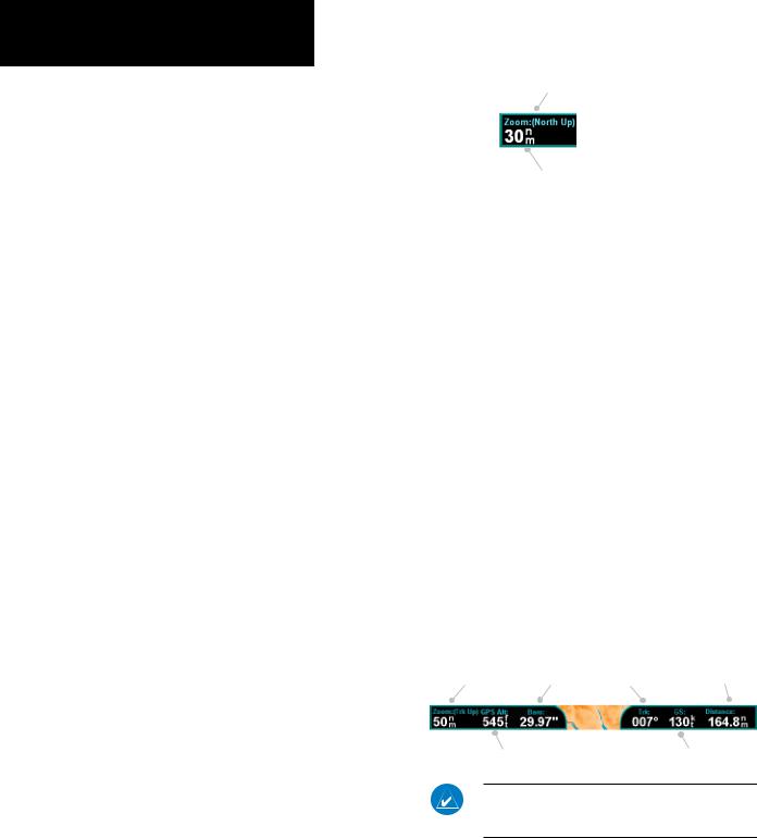
Detailed Operation
Custom Map
Custom Map (MAP)
The Custom Map function provides a graphical display of map features in relation to the aircraft location to help improve situational awareness. Review the Limitations section in the front of this guide that apply to using data displayed on the moving map. The custom map function is unique in allowing you to selectively “overlay” all available types of information onto a single display. Press the MENU/ENT key to display a list of options on the right side of the screen. Press the Menu Item key next to the displayed option. Repeated presses of the Menu Item key will scroll through the available selections for each option. Turning on too many layers may clutter the display.
The “smart” keys at the bottom of the display over the function keys control the map scale by zooming in or out, moving the map view around with the Pan feature, and viewing Info about the current destination waypoint.
Initial Zoom Level
The initial zoom level that is used on start-up is determined by a setting made in the System Function.
Map Scale
The In and Out function keys control the map scale by zooming in and out. You can zoom in to 0.25 NM and zoom out to 1250 NM. The scale distance is measured from the location of your aircraft symbol to the top of the screen. The Map Scale is shown in the lower left corner of the screen. The map orientation appears above the map scale.
Map Orientation
Map Orientation and
Zoom Level (Map
Scale)
Zoom Level
Auto Zoom
Auto Zoom is activated by adjusting the zoom level to the far extremes of the zoom range. When activated, the indicated zoom level will change from a number to the text “A,” followed by the zoom scale.
While in the Auto Zoom mode, the screen will automatically adjust the current zoom level to maintain the current “TO” waypoint on the screen. When approaching the waypoint, the zoom level will not drop below 2 NM. When the waypoint is reached and the next waypoint in the flight plan becomes active, the zoom level will automatically adjust to bring that waypoint on the map.
When installed with a GNS 480-series GPS receiver, the GMX 200 zoom level can be controlled by the GNS 480. This feature must be enabled in the System function with the “Slave Zoom to GPS Zoom” setting enabled.
To exit the autozoom mode, simply increase or decrease the current zoom level to re-enter the manual adjust mode.
|
|
|
Distance from |
|
Map Scale and |
Barometric |
|
Present Position to |
|
Track Angle |
Next Waypoint |
|||
Map Orientation |
Pressure |
GPS Altitude |
Ground Speed |
Above Mean Sea Level |
|
NOTE: GPS Altitude will likely not display the same values as instruments reporting pressure or barometric altitude.
16 |
190-00607-02 Rev D |

Pan
The Pan keys are used to move the display around so you can see beyond the initial boundaries of the screen. The PAN function key is one of the “smart” keys available at the bottom of the screen. Pressing the rotary knob will also activate the Pan function. When you select the Pan function, four “arrow” keys appear on the right side of the screen next to the
Menu Item keys. Move the map in the desired direction by pressing the Menu Item key next to the arrow that shows which way you want the map to move.
Press the PAN key again to exit the Pan mode. While panning, a green reference line is drawn from the center of the viewed area back to your current position.
Info
Press the INFO key to toggle viewing of information about the current “TO” waypoint. Press the INFO key again to hide the information.
Each press of the key will step through the available information for the current “TO” waypoint. The number of pages depends on the amount of information about the waypoint. Press the WX key to view any available METARs for the selected waypoint. Note that not all airports will have METARs available. The Wx key is available with the UAT, properly configured GDL 88, and GDL 69/69A FIS sensors.
Runway diagrams of airports will be displayed in the same orientation as the main map (i.e., North Up, Track Up, or DTK Up). If SafeTaxi information is available for the selected airport, the SafeTaxi detail will be shown.
Detailed Operation
Custom Map
Info page 1 |
Info page 2 |
Info page 3 |
Info page 3 with SafeTaxi |
Info page 4 |
Info Weather |
Info In Pan Mode |
|
The INFO smart key supports operation in conjunction with the PAN feature.
On any of the maps (Custom Map, IFR and VFR), entering the INFO mode while pan is active, will show information about the nearest airport to the center of the screen. This allows panning around the immediate area and obtaining information about airports in the vicinity without changing the current “TO” waypoint.
While in this mode, only the INFO smart key is highlighted. The PAN key is highlighted when exiting the Info mode. Only information about airports can be obtained with this feature.
190-00607-02 Rev D |
17 |
Detailed Operation
Custom Map
Custom Map Menu Option Page 1
The first option page of the Custom Map function lets you select options for the choices of Flight Plan, map orientation, Invert, Nav Data, and Load Chart.
The last option selection takes you to the next page of options. For menu items with tri-state options, the active option is color coded in the item key label. When the option is clear, the icons and labels are not displayed. When the option has a cyan background, icons and labels are all shown. When the option box has a white background, only the icons are shown.
Custom Map page with Menu Items (page 1)
Flight Plan
The Flight Plan option controls the display of the Flight Plan course line. Pressing the Menu Item key next to the Flight Plan option toggles between showing or not showing the Flight Plan route line.
If the flight plan provided by the navigator to the GMX 200 has an invalid cross track error, the ownship symbol will have a red “X” placed over it.
Map Orientation
This option controls the screen orientation in reference to the aircraft symbol. You may select from
North Up, Track Up, Track Up Arc, Track Up 360, and Desired Track Up. North Up sets magnetic north as the top of the screen. Track Up sets the current track of the aircraft as the top of the screen. Track Up Arc sets the current track of the aircraft and a 120° arc at the top of the screen. Track Up 360 sets the current track of the aircraft at the top of the screen and a 360° ring with the aircraft symbol position in the center. Desired Track Up sets the desired track to the next waypoint as the top of the screen. Press the Menu Item key next to this option to scroll through the options.
Invert
The Invert option changes the display of text and the background color. Depending on which layers are turned on, inverting the display may help readability for the current lighting conditions. For instance, when Terrain is shown, the Invert option switches between white and black text. When terrain is turned off, the Invert option switches between a white background with black text and a black background with white text.
Nav Data
The Nav Data option controls the display of navigation data. Subsequent presses of the Menu Item key for this option provides choices of no nav data, nav data in the corners (waypoint, bearing, zoom, and distance), or full nav data. The full nav data option includes the information in the four corners selection plus altitude, barometer setting, track, and ground speed.
NOTE: When the GMX 200 is configured for an external Terrain Awareness and Warning System (TAWS), the “Baro” and “Alt” fields normally present on the Navigational Bar in the Custom Map function will not be displayed.
18 |
190-00607-02 Rev D |
Loading...