


 Loading...
GNS 430/430A
Pilot’s Guide and Reference

RECORD OF REVISIONS
Part Number |
Change Summary |
190-00140-00 |
Made various layout corrections, no content changes |
(Rev. J) |
|
|
|
Revision |
Date of Revision |
Description |
A |
12/98 |
Initial Release |
B |
4/99 |
Update to conform to recent SW changes |
C |
6/99 |
Added Addendum |
D |
7/99 |
Update for SW 2.10 |
E |
4/00 |
Update for SW 2.15 |
F |
7/00 |
Updated Power On,Wind Vector, Crossfill, DME, and Fuel Plan |
G |
5/03 |
Added FDE Section, updated per SW 5.01, misc. changes |
H |
5/06 |
Changed to 8 inch x 8.5 inch format. Added TERRAIN, misc. |
|
|
changes |
GNS 430 Pilot’s Guide and Reference |
i |

COPYRIGHT
Copyright © 1998-2006 Garmin Ltd. or its subsidiaries.All rights reserved.
This manual reflects the operation of Main System Software version 5.01 or later. Some differences may be observed when comparing the information in this manual to other software versions.
Garmin International, Inc., 1200 East 151st Street, Olathe, Kansas 66062 USA
p: 913.397.8200 |
f: 913.397.8282 |
Garmin AT, Inc., 2345 Turner Road SE, Salem, Oregon 97302 USA |
|
p: 503.391.3411 |
f: 503.364.2138 |
Garmin (Europe) Ltd., Unit 5,The Quadrangle,Abbey Park, Industrial Estate, Romsey, SO51 9DL, U.K. |
|
p: 44/0870.8501241 |
f: 44/0870.8501251 |
Garmin (Asia) Corp., No. 68, Jangshu 2nd Road., Shijr,Taipei County,Taiwan |
|
p: 886/2.2642.9199 |
f : 886/2.2642-9099 |
Web Site Address: www.garmin.com
Visit the Garmin website for the latest updates and supplemental information concerning the operation of this and other Garmin products.
Except as expressly provided herein, no part of this manual may be reproduced, copied, transmitted, disseminated, downloaded or stored in any storage medium, for any purpose without the express written permission of Garmin. Garmin hereby grants permission to download a single copy of this manual and of any revision to this manual onto a hard drive or other electronic storage medium to be viewed for personal use, provided that such electronic or printed copy of this manual or revision must contain the complete text of this copyright notice and provided further that any unauthorized commercial distribution of this manual or any revision hereto is strictly prohibited.
Garmin®,AutoLocate®, and PhaseTrac12® are registered trademarks of Garmin Ltd. or its subsidiaries and may not be used without the express permission of Garmin.
GNS™ and Spell’N’Find™ are trademarks of Garmin Ltd. or its subsidiaries and may not be used without the express permission of Garmin.
NavData® is a registered trademark of Jeppesen, Inc.
June 2006 |
190-00140-00 Rev. J |
Printed in the U.S.A. |
ii |
GNS 430 Pilot’s Guide and Reference |

SECTION 1: INTRODUCTION........................................... |
1-1 |
|
1.1 |
Accessories and Packing List ................................. |
1-1 |
1.2 |
Key and Knob Functions ......................................... |
1-2 |
1.3 |
Takeoff Tour............................................................... |
1-5 |
SECTION 2: COM.................................................................. |
2-1 |
|
2.1 |
Communicating using the GNS 430...................... |
2-1 |
SECTION 3: NAV PAGES .................................................. |
3-1 |
|
3.1 |
Main Page Groups.................................................... |
3-1 |
3.2 |
NAV Page Group....................................................... |
3-1 |
3.3 |
Default NAV Page..................................................... |
3-2 |
3.4 |
Map Page ................................................................... |
3-5 |
3.5 |
TERRAIN Page.......................................................... |
3-14 |
3.6 |
NAV/COM Page........................................................ |
3-17 |
3.7 |
Position Page .......................................................... |
3-19 |
3.8 |
Satellite Status Page............................................. |
3-22 |
3.9 |
Vertical Navigation Page...................................... |
3-24 |
SECTION 4: DIRECT-TO NAVIGATION......................... |
4-1 |
|
4.1 |
Overview.................................................................... |
4-1 |
SECTION 5: FLIGHT PLANS ............................................. |
5-1 |
|
5.1 |
Flight Plan Catalog Page........................................ |
5-1 |
5.2 |
Active Flight Plan Page........................................... |
5-8 |
SECTION 6: PROCEDURES............................................... |
6-1 |
|
6.1 |
Approaches, Departures and Arrivals.................. |
6-1 |
6.2 |
Non-Precision Approach Operations.................... |
6-3 |
6.3 |
ILS Approaches ....................................................... |
6-26 |
6.4 |
Points to Remember for All Approaches .......... |
6-32 |
SECTION 7: WPT PAGES.................................................... |
7-1 |
|
7.1 |
WPT Page Group....................................................... |
7-1 |
7.2 |
Airport Location Page............................................. |
7-4 |
7.3 |
Airport Runway Page .............................................. |
7-5 |
7.4 |
Airport Frequency Page.......................................... |
7-6 |
7.5 |
Airport Approach Page ........................................... |
7-8 |
7.6 |
Airport Arrival Page............................................... |
7-11 |
7.7 |
Airport Departure Page........................................ |
7-13 |
7.8 |
Intersection Page................................................... |
7-14 |
7.9 |
NDB Page.................................................................. |
7-15 |
7.10 VOR Page................................................................ |
7-15 |
|
7.11 User Waypoint Page ............................................ |
7-17 |
|
|
|
|
TABLE OF CONTENTS |
|
|
|
|
||
SECTION 8: NRST PAGES ................................................. |
8-1 |
|||
8.1 |
NRST Page Group ..................................................... |
8-1 |
||
8.2 |
Nearest Airport Page............................................... |
8-4 |
||
8.3 |
Nearest Intersection Page...................................... |
8-6 |
||
8.4 |
Nearest NDB Page.................................................... |
8-6 |
||
8.5 |
Nearest VOR Page .................................................... |
8-6 |
||
8.6 |
Nearest User Waypoint Page................................. |
8-8 |
||
8.7 |
Nearest Center (ARTCC) Page................................ |
8-8 |
||
8.8 |
|
Nearest Flight Service Station (FSS) Page.......... |
8-9 |
|
8.9 |
Nearest Airspace Page.......................................... |
8-10 |
||
SECTION 9: VLOC RECEIVER........................................... |
9-1 |
|||
9.1 |
VLOC (VOR/LOCALIZER/GLIDESLOPE) Receiver |
|||
Operations......................................................................... |
9-1 |
|||
SECTION 10: AUX PAGES............................................... |
10-1 |
|||
10.1 |
AUX Page Group................................................... |
10-1 |
||
10.2 |
Flight Planning Page ........................................... |
10-2 |
||
10.3 |
Utility Page.......................................................... |
10-12 |
||
10.4 |
Setup 1 Page ....................................................... |
10-20 |
||
10.5 |
Setup 2 Page ....................................................... |
10-27 |
||
SECTION 11: TERRAIN INTERFACE............................ |
11-1 |
|||
11.1 |
Introduction .......................................................... |
11-1 |
||
11.2 |
TERRAIN Operation.............................................. |
11-2 |
||
11.3 |
TERRAIN Alerts...................................................... |
11-7 |
||
SECTION 12: FAULT DETECTION AND |
|
|||
EXCLUSION ............................................................................ |
12-1 |
|||
12.1 |
Detection and Exclusion..................................... |
12-1 |
||
12.2 |
Pre-Departure Verification of FDE.................... |
12-2 |
||
SECTION 13: MESSAGES, ABBREVIATIONS, AND |
||||
NAV TERMS............................................................................ |
13-1 |
|||
13.1 |
Messages................................................................ |
13-1 |
||
13.2 |
Abbreviations........................................................ |
13-9 |
||
13.3 |
Navigation Terms............................................... |
13-12 |
||
Appendix A: Data Card Use.......................................... |
A-1 |
|||
Appendix B: Specifications........................................... |
B-1 |
|||
Appendix C: Map Datums.............................................. |
C-1 |
|||
Appendix D: Troubleshooting Q & A....................... |
D-1 |
|||
GNS 430 Pilot’s Guide and Reference |
iii |

WARNINGS,
CAUTIONS, AND NOTES
WARNING: Navigation and terrain separation must NOT be predicated upon the use of the TERRAIN function. The TERRAIN feature is NOT intended to be used as a primary reference for terrain avoidance and does not relieve the pilot from the responsibility of being aware of surroundings during flight. The TERRAIN feature is only to be used as an aid for terrain avoidance and is not certified for use in applications requiring a certified terrain awareness system. Terrain data is obtained from third party sources. Garmin is not able to independently verify the accuracy of the terrain data.
WARNING: The terrain data should be used only as an aid for situational awareness. Terrain data must not be used as the sole basis for decisions or maneuvers to avoid terrain or obstacles. Terrain data must not be used for navigation.
WARNING: The altitude calculated by GNS 430 GPS receivers is geometric height above Mean Sea Level and could vary significantly from the altitude displayed by pressure altimeters in aircraft. GPS altitude should never be used for vertical navigation. Always use pressure altitude displayed by pressure altimeters in the aircraft.
WARNING: The Jeppesen database used in the GNS 430 system must be updated regularly in order to ensure that its information remains current. Updates are released every 28 days. A database information packet is included in the GNS 430 package. Pilots using an outdated database do so entirely at their own risk.
WARNING: The basemap (land and water data) must not be used for navigation, but rather only for nonnavigational situational awareness. Any basemap indication should be compared with other navigation sources.
WARNING: For safety reasons, GNS 430 operational procedures must be learned on the ground.
WARNING: The United States government operates the Global Positioning System and is solely responsible for its accuracy and maintenance. The GPS system is subject to changes which could affect the accuracy and performance of all GPS equipment. GPS accuracy may be degraded by the U.S.Department of Defense-imposed SelectiveAvailability (SA) program. With ‘SA’ on, GPS altitude may be in error by several hundred feet. Portions of the Garmin GNS 430 utilize GPS as a precision electronic NAVigation AID (NAVAID). Therefore, as with all NAVAIDs, information presented by the GNS 430 can be misused or misinterpreted and, therefore, become unsafe.
iv |
GNS 430 Pilot’s Guide and Reference |

WARNINGS,
CAUTIONS, AND NOTES
WARNING: Use the GNS 430 at your own risk. To reduce the risk of unsafe operation, carefully review and understand all aspects of the GNS 430 Pilot’s Guide documentation and the GNS 430 Flight Manual Supplement. Thoroughly practice basic operation prior to actual use. During flight operations, carefully compare indications from the GNS 430 to all available navigation sources, including the information from other NAVAIDs, visual sightings, charts, etc. For safety purposes, always resolve any discrepancies before continuing navigation.
CAUTION: The GNS 430 display lens is coated with a special anti-reflective coating that is very sensitive to skin oils,waxes,and abrasive cleaners. CLEANERS CONTAININGAMMONIAWILL HARMTHEANTI-REFLECTIVE COATING. It is very important to clean the lens using a clean, lint-free cloth and an eyeglass lens cleaner that is specified as safe for anti-reflective coatings.
CAUTION: The Garmin GNS 430 does not contain any user-serviceable parts. Repairs should only be made by an authorized Garmin service center. Unauthorized repairs or modifications could void both the warranty and the pilot’s authority to operate this device under FAA/FCC regulations.
NOTE:All visual depictions contained within this document, including screen images of the GNS 430 panel and displays, are subject to change and may not reflect the most current GNS 430 system. Depictions of equipment may differ slightly from the actual equipment.
NOTE:This device complies with part 15 of the FCC Rules. Operation is subject to the following two conditions:
(1) this device may not cause harmful interference, and (2) this device must accept any interference received, including interference that may cause undesired operation.
NOTE: Unless otherwise specified within this manual, the term ‘GNS 430’ applies to both the GNS 430 and the GNS 430A models. Please, note that the difference between these two models is indicated under ‘VHF COM Performance’ in the Specifications section of this manual (Appendix B).
NOTE: This product, its packaging, and its components contain chemicals known to the State of California to cause cancer, birth defects, or reproductive harm. This notice is being provided in accordance with California’s Proposition 65. If you have any questions or would like additional information, please refer to our website at www.garmin.com/prop65.
GNS 430 Pilot’s Guide and Reference |
v |

WARRANTY
LIMITED WARRANTY
This Garmin product is warranted to be free from defects in materials or workmanship for two years from the date of purchase. Within this period, Garmin will, at its sole option, repair or replace any components that fail in normal use. Such repairs or replacement will be made at no charge to the customer for parts and labor,provided that the customer shall be responsible for any transportation cost. This warranty does not cover failures due to abuse, misuse, accident, or unauthorized alterations or repairs.
THE WARRANTIES AND REMEDIES CONTAINED HEREIN ARE EXCLUSIVE AND IN LIEU OF ALL OTHER WARRANTIES EXPRESS OR IMPLIED OR STATUTORY, INCLUDING ANY LIABILITY ARISING UNDER ANY WARRANTY OF MERCHANTABILITY OR FITNESS FOR A PARTICULAR PURPOSE, STATUTORY OR OTHERWISE. THIS WARRANTY GIVES YOU SPECIFIC LEGAL RIGHTS, WHICH MAY VARY FROM STATE TO STATE.
IN NO EVENT SHALL GARMIN BE LIABLE FOR ANY INCIDENTAL, SPECIAL, INDIRECT OR CONSEQUENTIAL DAMAGES, WHETHER RESULTING FROMTHE USE,MISUSE,OR INABILITYTO USETHIS PRODUCT OR FROM DEFECTS INTHE PRODUCT. Some states do not allow the exclusion of incidental or consequential damages, so the above limitations may not apply to you.
Garmin retains the exclusive right to repair or replace the unit or software, or to offer a full refund of the purchase price, at its sole discretion. SUCH REMEDY SHALL BEYOUR SOLEAND EXCLUSIVE REMEDY FOR ANY BREACH OF WARRANTY.
To obtain warranty service, contact your local GarminAuthorized Service Center. For assistance in locating a Service Center near you, visit the Garmin Web site at “http://www.garmin.com” or contact Garmin Customer Service at 800-800-1020.
vi |
GNS 430 Pilot’s Guide and Reference |

SECTION 1: INTRODUCTION
1.1 ACCESSORIES AND PACKING LIST
Congratulations on choosing the finest, most advanced panel mount IFR navigation/communication system available. The GNS 430 represents Garmin’s commitment to provide accurate, easy-to-use avionics.
Before installing and getting started with the GNS 430, pleasechecktoseethatthepackageincludesthefollowing items. If any parts are missing or damaged, please contact a Garmin dealer immediately.
Standard Package:
•GNS 430 Unit, NavData® Card, and Terrain Data Card
•Installation Rack, Connectors, and GPS Antenna
•Pilot’s Guide and Quick Reference Guide
•400/500 Series Display Interface Pilot’s Guide Addendum
•Database Subscription Packet
•Warranty Registration Card
•GNS 430 Simulator CD-ROM
SECTION 1
INTRODUCTION
The Garmin dealer performs the installation and configuration of the GNS 430. The GNS 430 is secured in the installation rack with the proper wiring connections performed. After installation, the NavData card and the Terrain Data card (if applicable) are installed into the correct slot on the front of the unit (Appendix A). A Garmin dealer can answer questions about the installation such as location of antennas or any connections to other equipment in the panel.
NOTE: Help Garmin provide better support by completing our on-line registration. Registration ensures notification of product updates, new products, and provides for lost or stolen unit tracking. Have the serial number of the GNS 430 available and connect to our website (www. garmin.com). Look for the product registration link on the home page.
GNS 430 Pilot’s Guide and Reference |
1-1 |

SECTION 1
INTRODUCTION
1.2 KEY AND KNOB FUNCTIONS
The GNS 430 is designed to make operation as simple as possible. The key and knob descriptions (Figure 1-1) provide a general overview of the primary function(s) for each key and knob. The takeoff tour (Section 1.3) is intended to provide a brief overview of the primary functions of the GNS 430.
Experiment with the unit and refer to the reference sections for more information.
Data is entered using the large and small knobs. Experimentwiththemtobecomeefficientatenteringdata. This greatly reduces the amount of time spent operating the GNS 430 in flight.
1 |
2 |
3 |
4 |
5 |
6 |
7 |
8 |
9 |
10 |
11 |
12 |
13 |
14 |
15 |
16 |
17 |
18 |
Figure 1-1 Keys and Knobs
1
2
3
4
5
6
COM Power/Volume |
7 |
RNG (map range) |
13 |
OBS |
VLOC Volume |
8 |
MENU |
14 |
MSG (message) |
COM Flip-flop |
9 |
ENT (enter) |
15 |
FPL (flight plan) |
VLOC Flip-flop |
10 |
Small left knob |
16 |
PROC (procedures) |
CLR (clear) |
11 |
Large left knob |
17 |
Large right knob |
Direct-to |
12 |
CDI |
18 |
Small right knob |
1-2 |
GNS 430 Pilot’s Guide and Reference |
Left-hand Keys and Knobs
The COM Power/Volume Knob controls unit power and communications radio volume. Press momentarily to disable automatic squelch control.
The VLOC Volume Knob controls audio volume for the selected VOR/Localizer frequency. Press momentarily to enable/disable the ident tone.
The large left knob (COM/VLOC) is used to tune the megahertz (MHz) value of the standby frequency for the communicationstransceiver(COM)ortheVLOCreceiver, whichever is currently selected by the tuning cursor.
The small left knob (COM/VLOC) is used to tune the kilohertz (kHz) value of the standby frequency for the communications transceiver (COM) or the VLOC receiver, whichever is currently selected by the tuning cursor. Press this knob momentarily to toggle the tuning cursor between the COM and VLOC frequency fields.
The COM Flip-flop Key is used to swap the active and standby COM frequencies. Press and hold to select emergency channel (121.500 MHz).
The VLOC Flip-flop Key is used to swap the active and standby VLOC frequencies (i.e., make the selected standby frequency active).
SECTION 1
INTRODUCTION
Right-hand Keys and Knobs
The RNG Key allows the pilot to select the desired map range. Use the up arrow to zoom out to a larger area, or the down arrow to zoom in to a smaller area.
The Direct-to Key provides access to the direct-to function, which allows the pilot to enter a destination waypoint and establishes a direct course to the selected destination (Section 4).
The MENU Key displays a context-sensitive list of options. This options list allows the pilot to access additional features or make settings changes which relate to the currently displayed page.
The CLR Key is used to erase information, remove map detail, or to cancel an entry. Press and hold the CLR key to immediately display the Default NAV Page.
The ENT Key is used to approve an operation or completedataentry. Itisalsousedtoconfirminformation, such as during power on.
The large right knob is used to select between the various page groups: NAV, WPT, AUX, or NRST. With the on-screen cursor enabled, the large right knob allows the pilot to move the cursor about the page. The large right knob is also used to move the target pointer right (turn clockwise) or left (counterclockwise) when the map panning function is active.
The small right knob is used to select between the various pages within one of the groups listed above. Press this knob momentarily to display the on-screen cursor. The cursor allows the pilot to enter data and/or make a selection from a list of options. When entering data, the small knob is used to select the desired letter or number and the large knob is used to move to the next character space. Thesmallrightknobisalsousedtomovethetarget pointer up (turn clockwise) or down (counterclockwise) when the map panning function is active.
GNS 430 Pilot’s Guide and Reference |
1-3 |

SECTION 1
INTRODUCTION
NOTE: When the GNS 430 is displaying a list of information that is too long for the display screen,a scroll bar appears along the right-hand side of the display (Figure 1-2). The scroll bar graphically indicates the number of additional items available within the selected category. To scroll through the list,press the small right knob to activate the cursor, then turn the large right knob.
Scroll Bar
Figure 1-2 Scroll Bar
Bottom Row Keys
The CDIKey is used to toggle which navigation source (GPS or VLOC) provides output to an external HSI or CDI.
The OBS Key is used to select manual or automatic sequencing of waypoints. Pressing the OBS Key selects OBS mode, which retains the current ‘active to’ waypoint asthenavigationreferenceevenafterpassingthewaypoint (i.e., prevents sequencing to the next waypoint). Pressing the OBS Key again returns the unit to normal operation, with automatic sequencing of waypoints. When OBS mode is selected, the pilot may set the desired course to/from a waypoint using the ‘Select OBS Course’ pop-up window, or an external OBS selector on the HSI or CDI.
The MSG Key is used to view system messages and to alert the pilot to important warnings and requirements. See Section 13.1 for more information on messages.
The FPL Key allows the pilot to create, edit, activate, and invert flight plans, as well as access approaches, departures, and arrivals. A closest point to flight plan feature is also available from the FPL Key. See Section 5 for more information on flight plans.
The PROC Key allows the pilot to select and remove approaches, departures, and arrivals from the flight plan. When using a flight plan, available procedures for the departure and/or arrival airport are offered automatically. Otherwise, the pilot may select the desired airport, then the desired procedure.
1-4 |
GNS 430 Pilot’s Guide and Reference |

1.3 TAKEOFF TOUR
Overview
The Garmin GNS 430 provides the pilot accurate navigational data and communication capability, along with non-precision and precision approach certification in the IFR environment. The takeoff tour is designed to familiarize the pilot with the operation of the GNS 430 by :
•Powering up the unit
•Changing frequencies
•Entering data
•Performing a simple direct-to
•Selecting IFR procedures
•Using some limited flight plans
In addition, this section briefly covers the Default NAV Page, the Map Page, and the NAV/COM Page, which are available as part of the NAV Page Group. These pages are used for most of the in-flight navigation.
The takeoff tour assumes that the unit and antennas have been properly installed and that the GNS 430’s default settings have not been changed. If any of the factory default settings (position format, units of measure, selectable fields, etc.) have been changed, the pictures shown here may not exactly match what is shown on the GNS 430. Prior to using the GNS 430 for the first time, Garmin recommends that the aircraft be moved to a location that is well away from buildings and other aircraft so the unit can collect satellite data without interruption.
This takeoff tour is intended to provide a brief introduction of the GNS 430’s major features. Sections 2 through 13 of this manual describe these features, and others, in additional detail. Refer to these sections, as needed,tolearnorreviewthedetailsregardingaparticular feature.
SECTION 1
INTRODUCTION
Afterbecomingfamiliarwiththebasics,somesuggested reading within this Pilot’s Guide includes:
•Flight plan features - Section 5
•Waypoint information pages (database information) - Section 7
•IFR procedures - Section 6
•Unit settings (configuring the unit to the pilot’s preferences) - Section 10
If more information is needed, Garmin’s Customer Service staff is available during normal business hours (U.S. Central time zone) at the phone and fax numbers listed on page ii. Garmin can also be reached by mail (page ii) or at our web site address, www.garmin.com.
Powering up the GNS 430
The GNS 430’s power and COM volume are controlled usingtheCOMPower/Volumeknobatthetopleftcorner of the unit. Turning it clockwise turns unit power on and increases the COM radio volume. After turning the unit on, a welcome page (Figure 1-3) is displayed while the unitperformsaselftest,followedsequentiallybytheLand Data Page, then (if configured for TERRAIN) the Terrain Data Page, the Obstacle Data Page, and the Airport Terrain Data Page.
Figure 1-3 Welcome Page
GNS 430 Pilot’s Guide and Reference |
1-5 |

SECTION 1
INTRODUCTION
The Database Confirmation Page (Figure 1-4) appears next, which shows the current database information on the NavData card (with the valid operating dates, cycle number, and database type indicated). The database is updated every 28 days, and must be current for approved instrument approach operations. Information on database subscriptions is available inside the GNS 430 package.
Figure 1-4 Database Confirmation Page
To acknowledge the database information:
Press the ENT Key.
Once the database has been acknowledged, the Instrument Panel Self-test Page appears (Figure 1-5).
Figure 1-5 Instrument Panel Self-Test Page
Instrument Panel Self-test Page
To ensure that the GNS 430 and any connected instruments are working properly, check for the following indications on the CDI/HSI, RMI, external annunciators, and other connected instruments:
•Course deviation - Half left/no flag
•TO/FROM flag - TO
•Bearing to destination - 135°
•Distance to dest. - 10.0 nautical mile (nm)
•All external annunciators (if installed) - On
•Glideslope - Half up/no flag
•Time to destination - 4 minutes
•Desired track - 149.5°
•Ground speed - 150 knots
The Instrument Panel Self-test Page (Figure 1-5) indicates the currently selected OBS course, fuel capacity (CAP), fuel on board (FOB), and fuel flow (FF). The fuel capacity, fuel on board, and fuel flow may be manually entered if the installation does not include connection to sensors which automatically provide these figures.
To enter fuel capacity, fuel on board or fuel flow figures (if not provided by sensors):
1)Turn the large right knob to select the ‘CAP’, ‘FOB’, or ‘FF’ field.
1-6 |
GNS 430 Pilot’s Guide and Reference |

2)Turn the small and large right knobs to enter the desired figure (Figures 1-5 and 1-6) and press the ENT Key.
SECTION 1
INTRODUCTION
To view the Checklists Page:
1)Turn the large right knob to highlight ‘Go To Chklist?’ (Figure 1-8) and press the ENT Key.
Figure 1-6 Fuel Flow Selected
The Instrument Panel Self-test Page includes selections to set fuel on board (FOB) to full capacity and access the Checklists Page. This allows the pilot to quickly set fuel to full limits and display any checklists that have been entered, such as start up or takeoff checklists.
To set fuel on board to full (if not provided by sensor):
1)Turn the large right knob to highlight‘Set Full Fuel?’ (Figure 1-7).
Figure 1-7 ‘Set Full Fuel?’ Highlighted
2)Press the ENTKey and verify that fuel on board (‘FOB’) now matches the fuel capacity (CAP) figure. Fuel on board is reduced, over time, based on the fuel flow (FF) figure.
Figure 1-8 ‘Go To Chklist?’ Highlighted
2)Turn the large right knob to select the desired checklist, then execute each step (Section 10.3, Utility Page: Checklists) in the selected checklist.
3)Oncethepilotcompletesthedesiredchecklist(s), press the small right knob to return to the Checklists Page. Press the small right knob again to return to normal operation on the Satellite Status Page or the Map Page.
4)Once instrument operation has been verified with the Instrument Panel Self-test Page displayed, press the ENT Key.
NOTE: The GNS 430 can hold up to nine checklists with up to 30 entries in each checklist.
GNS 430 Pilot’s Guide and Reference |
1-7 |
SECTION 1
INTRODUCTION
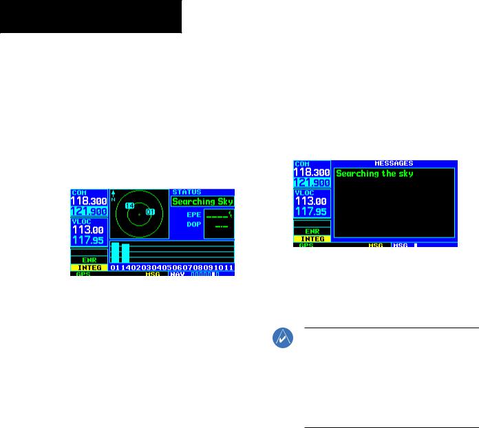
Satellite Status Page
The Satellite Status Page (Figure 1-9) appears as the GNS 430 attempts to collect satellite information.
When an ‘Acquiring’ status is displayed on the Satellite Status Page, the signal strengths of any satellites received appear as ‘bar graph’ readings. This is a good indication that the unit is receiving signals and a position fix is being determined. Following the first-time use of the GNS 430, the time required for a position fix varies, usually from one to two minutes.
Figure 1-9 Satellite Status Page
If the unit can only obtain enough satellites for 2D navigation(noaltitude),theunitusesthealtitudeprovided by the altitude encoder (if one is connected).
The ‘INTEG’ annunciator (bottom left corner of the screen) indicates that satellite coverage is insufficient to pass built-in integrity monitoring tests. In the example above,notenoughsatellitesarebeingreceivedtodetermine aposition. TheSatelliteStatusPageshowstheIDnumbers for the satellites and the relative signal strength of each satellite received (as a ‘bar graph’ reading).
‘Searching Sky’ indicates that satellite almanac data is not available or has expired (if the unit hasn’t been used for six months or more). This means the unit is acquiring satellite data to establish almanac and satellite orbit information, which can take five to ten minutes. The data is recollected from the first available satellite. The Satellite Status Page displays a ‘Search Sky’ status, and the message
annunciator (MSG), above the MSG Key also flashes to alert the pilot of system message, ‘Searching the Sky’.
To view a system message:
Press the MSG Key (Figure 1-10).
The Message Page appears and displays the status or warning information applicable to the receiver’s current operating condition.
Figure 1-10 Message Page
To return to the previous page after viewing a message:
Press the MSG Key again.
NOTE: The GNS 430 utilizes certain software algorithms to ensure reliable GPS receiver operation. Receiver Autonomous Integrity Monitoring (RAIM) and Fault Detection and Exclusion (FDE) are two examples. These features allow navigation during Oceanic/Remote legs of a flight using the GNS 430. For further details, please refer to Sections 10.3 and 12.
1-8 |
GNS 430 Pilot’s Guide and Reference |
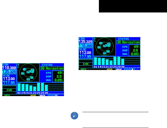
Selecting COM and VLOC Frequencies
While the GNS 430 is acquiring a position, take a minute to dial in the active and standby frequencies to be used for the first phase of the flight. The GNS 430’s display is divided into separate ‘windows’ (or screen areas), including a COM Window, VLOC Window, and the GPS Window (Figure 1-11).
|
|
COM Window; |
GPS Window |
||||
Active Frequency |
|
|
|
|
|||
|
|
|
|||||
|
|
|
|
|
|
|
|
|
|
|
|
|
|
||
Standby Frequency |
|
|
|||||
|
|
|
|
|
|
|
|
VLOC
Window
Figure 1-11 Standby Frequency 135.325 MHz
Pressing the small left knob activates the tuning cursor in the desired frequency window. To select the active frequency, first enter the frequency in the standby field, and use the COM Flip-flop (or the NAV Flip-flop) Key to move it to the active field.
To change the standby communication frequency:
1)Press the small left knob if needed, to move the tuning cursor to the COMWindow (Figure 1-11).
2)Turn the large left knob to select the MHz, and the small left knob to select the kHz of the desired frequency.
SECTION 1
INTRODUCTION
To place the standby communication frequency in the active field:
Press the COM Flip-flop Key (Figure 1-12).
Figure 1-12 Active Frequency 135.325 MHz
Once the active frequency has been entered, repeat steps 1 and 2 to enter the standby frequency. After both communication frequencies have been entered, the COM Window may be kept ‘hot’ by leaving the cursor on the standbyfrequency. MovethecursortotheVLOCWindow by pressing the small left knob.
NOTE: When selecting VLOC frequencies, the tuning cursor automatically returns to the COM Window after 30 seconds of inactivity.
To change the standby VLOC frequency:
1)Press the small left knob if needed,to activate the tuning cursor in the VLOC Window.
2)Turn the large left knob to select the MHz, and the small left knob to select the kHz of the desired frequency.
To place the standby frequency in the active field:
Press the NAV Flip-flop Key.
GNS 430 Pilot’s Guide and Reference |
1-9 |

SECTION 1
INTRODUCTION
Page Groups
Page Groups
NAV Group |
WPT Group |
AUX Group |
NRST Group |
see Section 3 |
see Section 7 |
see Section 10 |
see Section 8 |
Table 1-1 Page Groups
The bottom right corner of the screen (Figure 1-13) indicates which page group (Table 1-1) is currently being displayed,thenumberofpagesavailablewithinthatgroup (indicated by square icons), and the placement of the current page within that group (indicated by a highlighted square icon).
InadditiontotheNAVPageGroup,additionalpagegroups are available for waypoint information (WPT), auxiliary (AUX) functions such as flight planning or unit settings, and listings for nearest (NRST) airports or other facilities.
Position of
Current Page
 within Current
Page Group
Current Page Group |
Number of Pages in |
|
Current Page Group |
||
|
Figure 1-13 Current Page and Page Group
To select the desired page group:
Turn the large right knob until a page from the desired page group is displayed (Figure 1-13).
To select the desired page within the page group:
Turn the small right knob until the desired page is displayed (Figure 1-13).
NAV Pages
There are seven pages available under the NAV Page
Group*:
•Default NAV Page
•Map Page
•TERRAIN Page
•NAV/COM Page
•Position Page
•Satellite Status Page
•Vertical Navigation Page
The Default NAV Page, the Map Page, and the NAV/ COM Page are used for most of the in-flight navigation.
NOTE: *Eight NAV pages are available when the GNS 430 installation includes connection to traffic and/or weather information sources. See the 400/500 Series Display Interfaces Pilot’s Guide Addendum, p/n 190-00140-10, or the 400/500 Series Garmin Optional Displays Pilot’s Guide Addendum, p/n 190-00140-13.
To select the NAV Page Group and display the Default NAV Page:
Press and hold the CLR Key.
To select the desired NAV Page:
Turn the small right knob until the desired page is displayed.
1-10 |
GNS 430 Pilot’s Guide and Reference |
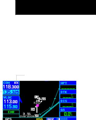
Map Page
After the GNS 430 acquires satellites and computes a position, the Map Page (Figure 1-14) appears automatically.
|
Map Display |
|
|
Data Fields |
|||
|
|
|
|
|
Desired Track |
|
|
Map Range |
|
Present Position |
|
|
|||
|
|
|
|
|
|
||
|
|
|
|
|
|
|
|
|
|
|
|
|
|
|
|
|
|
|
|
|
|
|
|
|
|
|
|
|
|
|
|
|
|
|
|
|
|
|
|
Figure 1-14 Map Page
The Map Page displays the present position (using an airplane symbol) relative to nearby airports, VORs, NDBs, intersections, user waypoints, and airspace boundaries. The route is displayed as a solid line.
Data fields for destination waypoint (WPT), distance towaypoint(DIS),desiredtrack(DTK),andgroundspeed (GS) appear on the right-hand side of the display. These fields are user selectable (Section 3.4, Selecting Desired On-screen Data) to allow the pilot to configure the unit. Available settings include: altitude, bearing, enroute safe altitude, estimated time of arrival, minimum safe altitude, and ground track.
A Map Setup Page is provided to designate the maximum range at which each map feature appears. These settings provide an automatic decluttering of the map (based upon preferences) while adjusting the range. See Section 13.3 for definitions of these navigation terms.
While viewing the Map Page, the pilot can quickly declutterandremovemanyofthebackgroundmapdetails by pressing the CLR Key (repeatedly) until the desired detail is depicted.
SECTION 1
INTRODUCTION
To change the map range, press the up arrow (to zoom out) or the down arrow (to zoom in) of the RNG (map range) Key. The current map range is depicted in the lower left corner of the Map Display.
Direct-to Navigation
The GNS 430 can use direct point-to-point navigation to provide guidance from takeoff to touchdown, even in the IFR environment. Once a destination is selected, the unit provides speed, course, and distance data based upon a direct course from the present position to the destination. A destination can be selected from any page with the Direct-to Key.
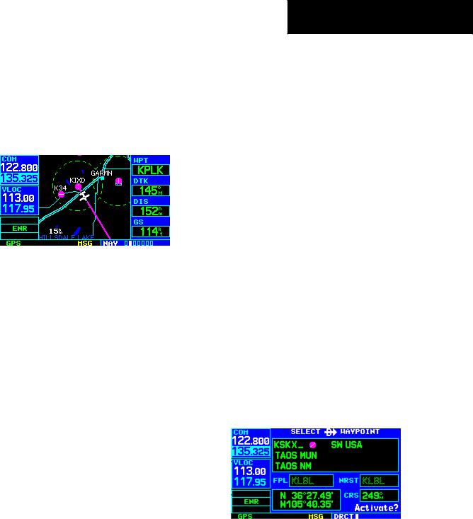
To select a direct-to destination:
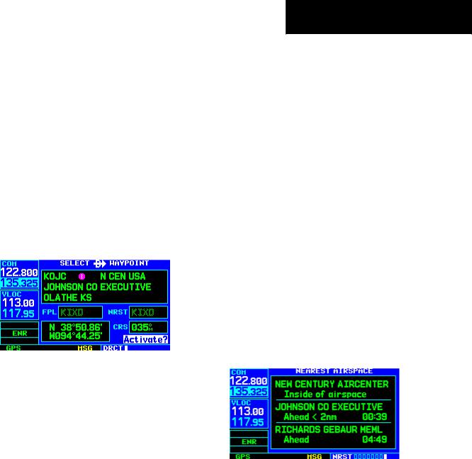
1)Press the Direct-to Key. The Select Direct-to Waypoint Page appears with the destination field highlighted.
2)Turn the small right knob to enter the first letter of the destination waypoint identifier. The destination waypoint may be an airport, VOR, NDB, intersection, or user waypoint, as long as it is in the database or stored in memory as a user waypoint.
3)Turn the large right knob to the right to move the cursor to the next character position.
4)Repeat steps 2 and 3 to spell out the rest of the waypoint identifier (Figure 1-15).
Figure 1-15 Direct-to Waypoint Page
GNS 430 Pilot’s Guide and Reference |
1-11 |

SECTION 1
INTRODUCTION
5)Press the ENTKey to confirm the identifier. The ‘Activate?’ function field is highlighted (Figure 1-16).
Figure 1-16 ‘Activate?’ Highlighted
6)Press the ENTKey to activate a direct-to course to the selected destination.
Once a direct-to destination is selected, press and hold the CLR Key to display the Default NAV Page.
Default NAV Page
During most flights, the Default NAV Page, the Map Page, and the NAV/COM Page are the primary pages used for navigation.
To select the Default NAV Page:
Press and hold the CLR Key (Figure 1-17).
TO/FROM Flag |
Course Deviation |
|||
|
Indicator (CDI) |
|||
|
|
|
|
|
|
|
|
|
|
Figure 1-17 Default NAV Page
The Default NAV Page (Figure 1-17) displays a graphic coursedeviationindicator(CDI),theactivelegoftheflight plan (as defined by the current ‘from’ and ‘to’ waypoints), and six user-selectable data fields. The default settings for these fields are distance to waypoint (DIS), desired track (DTK), bearing to waypoint (BRG), ground speed (GS), ground track (TRK), and estimated time enroute (ETE). See Section 13.3 for definitions of these navigation terms.
To change the data fields:
1)From the Default NAV page, press the MENU Key and select ‘Change Fields?’ (Figure 1-18).
Figure 1-18 Default NAV Page Menu
2)Turn the large right knob to select the data field to be changed.
3)Turn the small right knob to display a list of data options (Figure 1-19).
Figure 1-19 ‘Select Field Type’ Window
4)Press the ENT Key to select the desired data item and return to the Default NAV Page.
1-12 |
GNS 430 Pilot’s Guide and Reference |
NAV/COM Page
From the Default NAV Page, turn the small right knob until the NAV/COM Page (Figure 1-20) is displayed.
Departure, Enroute, or |
Frequency List |
Arrival Airport |
Frequency Type
Figure 1-20 NAV/COM Page
The NAV/COM Page displays the available frequencies (communicationsandnavigation)forthedepartureairport, any enroute airports which are included in the flight plan, and the final destination airport. When using the directto function, frequencies are listed for the airport nearest to the starting position and the destination airport.
To display the frequency list for the desired flight plan or direct-to airport:
1)Press the small right knob to activate the cursor on the airport identifier field (in the GPS Window).
2)Turn the small right knob to display the list of airports (departure,arrival,and enroute) for the flight plan or direct-to. Continue to turn the small right knob until the desired airport is selected.
3)Press the ENT Key to display the frequency list for the selected airport.
SECTION 1
INTRODUCTION
A frequency listed on the NAV/COM Page can be quickly transferred to the standby field of the COM Window or the VLOC Window. This time-saving process prevents having to ‘re-key’ a frequency already displayed elsewhere on the screen.
To select a communication or navigation frequency:
1)Press the small right knob to activate the cursor in the GPS Window.
2)Turn the large right knob to select the desired frequency from the list.
3)Press the ENT Key to transfer the selected frequency to the standby field in the COM or VLOCWindow. COM frequenciesautomatically gotothestandbyfieldofthe COMWindowand navigation frequencies automatically go to the standby field of the VLOC Window, regardless of which window is currently highlighted by the cursor.
4)To activate the selected frequency, press the
COM or VLOC Flip-flop Key.
GNS 430 Pilot’s Guide and Reference |
1-13 |
SECTION 1
INTRODUCTION
To display frequencies for a different airport along the flight plan.
1)Press the small right knob to highlight the airport identifier field.
2)Turn the small right knob to display the list of airports within the flight plan (Figure 1-21).
Figure 1-21 Airport Window
3)Continue turning the small rightknob to select the desired airport and press the ENT Key.
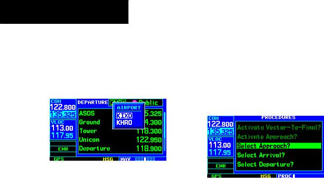
IFR Procedures
Oncethedirect-toorflightplanisconfirmed,thewhole range of instrument procedures is available. Departures (SIDs), arrivals (STARs), non-precision and precision approaches are stored within the NavData card and are available using the PROC (procedures) Key.
To display the Procedures Page (Figure 1-22), press the
PROC Key.
Figure 1-22 Procedures Page
The steps required to select and activate an approach, departure, or arrival are identical. In this introductory section, there are examples of the steps required to select an approach, but keep in mind the same process also applies to departures and arrivals.
To select an approach, departure, or arrival:
1)Turn the large right knob to select the desired option (‘Select Approach?’, ‘Select Arrival?’, or ‘Select Departure?’) from the Procedures Page.
2)Press the ENT Key to display a list of available procedures for the arrival (when using approaches orSTARs) or departure (when using SIDs) airport.
3)Turn the small right knob to select the desired procedure and press the ENT Key.
1-14 |
GNS 430 Pilot’s Guide and Reference |

4)For approaches, a window appears (Figure 1-23) to select the desired initial approach fix (IAF) or provide a ‘vectors’ option to select just the final course segment of the approach. Turn the small right knob to select the desired option and press the ENT Key. (The ‘vectors’ optionextends the finalinbound course beyond the final approach fix, allowing the pilot to intercept the final course segment beyond its normal limits.)
Figure 1-23 Approach Window
5)For departures and arrivals,a window appears to select the desired transition. Turn the small right knob to select the desired option and press the ENT Key.
In the flight plan or direct-to, the departure or arrival airport is replaced with the sequence of waypoints contained within the selected procedure.
SECTION 1
INTRODUCTION
Nearest (NRST) Pages
The NRST Page Group provides detailed information on the nine nearest airports, VORs, NDBs, intersections, and user-created waypoints within 200 nm of the current position. In addition, pages are also provided to display the five nearest center (ARTCC/FIR) and Flight Service Station (FSS) points of communication, plus alert the pilot to any nearby special-use or controlled airspaces.
The Nearest Airport Page (Figure 1-24) is one of eight pages available in the NRST group:
•Nearest Airport Page
•Nearest NDB Page
•Nearest User Waypoints Page
•Nearest FSS Page
•Nearest Intersection Page
•Nearest VOR Page
•Nearest ARTCC Page
•Nearest Airspace Page
The communication frequencies and runway information may both be examined directly from the Nearest Airport Page. As discussed earlier for the NAV/ COM Page, the pilot may also place any displayed frequency into the standby COM or VLOC field by highlighting the frequency with the cursor and pressing the ENT Key.
GNS 430 Pilot’s Guide and Reference |
1-15 |

SECTION 1
INTRODUCTION
To display the NRST pages:
1)If necessary, press and hold the CLR Key to select the NAV group and display the Default NAV Page.
2)Turn the large right knob to select the NRST Page Group, as indicated by ‘NRST’ appearing in the lower right corner of the screen.
3)Turn the small right knob to select the desired NRST Page.
To display a list of nearby airports:
1)Turn the large right knob to select the NRST Page Group and (if needed) the small right knob to select the NearestAirport Page (Figure 1-24).
To view additional information for a nearby airport:
1)Press the small right knob to activate the cursor.
2)Turn the large right knob to select the desired airport from the list.
3)Press the ENT Key to display waypoint (WPT) information pages for the selected airport (Figure 1-26).
Figure 1-26 Airport Location Page
4) To display runway and frequency information, press the small right knob to remove the cursor and turn the small right knob to display
the desired information page.
Figure 1-24 Nearest Airport Page
The Nearest Airport Page may be used in conjunction
2)To scroll through the list,press the small right with the Direct-to Key to quickly set a course to a nearby
knob, then turn the large right knob (Figure 1-25)
facility in an in-flight emergency. Selecting a nearby airport as a direct-to destination overrides the flight plan orcancelsapreviouslyselecteddirect-todestination. (The pilot still has the option of returning to the flight plan by cancelling the direct-to; see Section 4.1, Cancelling Direct-to Navigation.)
Figure 1-25 Scrolling the Nearest Airport List
1-16 |
GNS 430 Pilot’s Guide and Reference |
To select a nearby airport as a direct-to destination from the Nearest Airport Page:
1)From the NearestAirport Page,press the small right knob to activate the cursor.
2)Turn the large right knob to select the desired airport from the list.
3)Press the Direct-to Key, the ENT Key, and the ENT Key (again) to navigate to the nearby airport.
To select a nearby airport as a direct-to destination from the Airport Information Page:
1)Press the Direct-to Key, then press the ENT Key (Figure 1-27).
Figure 1-27 ‘Activate?’ Highlighted
2)Press the ENT Key again to navigate to the nearby airport.
SECTION 1
INTRODUCTION
Nearest (NRST) Airspace Page
The last page in the NRST group, the Nearest Airspace Page (Figure 1-28), provides information for up to nine controlled or special-use airspaces near or in the flight path. Airspace information appears on this page based upon the same criteria used for airspace alert messages. Nearby airspace information and airspace alert messages are provided according to the following conditions:
•If the projected course will take the aircraft inside an airspace within the next ten minutes, the message ‘Airspace ahead -- less than 10 minutes’ appears.
•If the aircraft is within two nautical miles of an airspace and the current course will take it inside of the airspace, the message ‘Airspace near and ahead’ appears.
•If the aircraft is within two nautical miles of an airspace and the current course will not take it inside of the airspace, the message ‘Near airspace less than 2nm’ appears.
•If the aircraft has entered an airspace, the message ‘Inside airspace’ appears.
Figure 1-28 Nearest Airspace Page
GNS 430 Pilot’s Guide and Reference |
1-17 |

SECTION 1
INTRODUCTION
Bydefault,airspacealertmessagesareturnedoff. When turned on, the message (MSG) annunciator located directly above the MSG Key flashes to alert the pilot to the airspace message. See Section 10.4, Setup 1 Page: Airspace Alarms for information on enabling airspace alert messages.
To view an airspace alert message:
1)Press the MSG Key. The Messages Page appears with the alert message (Figure 1-29).
Flight Plans (FPL)
The GNS 430 lets the pilot create up to 20 flight plans with up to 31 waypoints in each flight plan. Flight plans are created, edited, and activated using the FPL Key. The FPLPageGroupincludestwopages:theActiveFlightPlan Page and the Flight Plan Catalog Page (Figures 1-30 and 1-31). The Active Flight Plan Page provides information and editing features for the flight plan currently in use (referred to as ‘flight plan 00’). The Flight Plan Catalog Page serves as the main page for creating new flight plans, as well as editing or activating previously created flight plans.
Figure 1-29 Messages Page
2)Press the MSG Key again to return to the previous display.
Note that the airspace alerts are based upon threedimensional data (latitude, longitude, and altitude) to avoid nuisance alerts. The alert boundaries for controlled airspace are also sectorized to provide complete information on any nearby airspace. Additional information about a nearby airspace—such as controlling agency, frequency, and floor/ceiling limits—is available from the Nearest Airspace Page (Section 8.9).
To view additional airspace information:
1)Press the small right knob to activate the cursor.
2)Turn the large right knob to select the desired airspace from the list.
3)Press the ENT Key to view the airspace information.
Figure 1-30 Active Flight Plan Page
Figure 1-31 Flight Plan Catalog Page
1-18 |
GNS 430 Pilot’s Guide and Reference |

Since using flight plans is arguably one of the more complex features of the GNS 430, it will be discussed only briefly here, with focus on creating a new flight plan and activating it to use for navigation. Answers to additional questions about flight plans not found in this brief introduction can be found in Section 5, Flight Plans.
To create a new flight plan:
1)Press the FPL Key.
2)Turn the small right knob to select the Flight Plan Catalog Page.
3)Press the MENU Key to display the Flight Plan Catalog Page Menu (Figure 1-32).
Figure 1-32 Flight Plan Catalog Page Menu
4)Turn the large rightknob to select‘Create New Flight Plan?’ and press the ENT Key.
5)Thecursorappearsonthefirstwaypointidentifier field (located directly below‘WAYPOINT’). Use the large and small right knobs to enter the identifier of the first waypoint in the flight plan. (The small knob is used to select the desired letter or number and the large knob is used to move to the next character space.)
6)Press the ENT Key once the identifier has been selected. The cursor moves to the next blank waypoint identifier field.
SECTION 1
INTRODUCTION
7)Repeat steps 5 and 6,above,until all waypoints for the flight plan have been entered (Figure 1-33).
Figure 1-33 Enter Flight Plan Waypoints
Oncetheflightplaniscreated,itmaybeactivatedfrom the Flight Plan Catalog Page Menu. Activating the flight plan places it into ‘flight plan 00’ (a copy of it still resides in the original catalog location) and replaces any flight plan which currently exists in ‘flight plan 00’.
To activate the new flight plan:
1)Press the MENU Key to display the Flight Plan Catalog Page Menu.
2)Turn the small right knob to select ‘Activate Flight Plan?’ (Figure 1-34) and press the ENT Key
Figure 1-34 Flight Plan Catalog Page Menu
GNS 430 Pilot’s Guide and Reference |
1-19 |

SECTION 1
INTRODUCTION
Blank Page
1-20 |
GNS 430 Pilot’s Guide and Reference |
SECTION 2: COM
2.1 COMMUNICATING USING THE GNS 430
TheGNS430featuresadigitally-tunedVHFCOMradio that provides a seamless transition from communication to navigation, bringing the two most important functions in flying together in one panel-mounted unit. The GNS 430’s COM radio operates in the aviation voice band, from 118.000 to 136.975 MHz, in 25 kHz steps (default). For European operations, a COM radio configuration to allow for 8.33 kHz steps is also provided (Section 10.5, Setup 2 Page: COM Configuration).
Volume
COM radio volume is adjusted using the COM Power/ Volume Knob. Turn the COM Power/Volume Knob clockwise to increase volume, or counterclockwise to decrease volume.
Squelch
The COM radio features an automatic squelch, providing maximum sensitivity to weaker signals while rejecting many localized noise sources. The pilot may wish to override this automatic squelch function when listening to a distant station or when setting the desired volume level. The COM Power/Volume Knob allows the pilot to disable the automatic squelch and keep the COM audio open continuously. To override the automatic squelch, press the COM Power/Volume Knob momentarily. Press the COM Power/Volume Knob again to return to automatic squelch operation.
SECTION 2
COM
COM Window and Tuning
Communication frequencies are selected with the tuning cursor in the standby COM frequency field (Figure 2-1), using the small and large left knobs to dial in the desired frequency. The standby frequency always appears below the active frequency. The active frequency is the frequency currently in use for transmit and receive operations.
‘RX’ Receive Indication
Standby COM
Frequency Field
Figure 2-1 ‘RX’ Receive Indication
A frequency may also be quickly selected from the database by simply highlighting the desired frequency on any of the main pages and pressing the ENT Key. This process is referred to as auto-tuning. Once a frequency is selected in the standby field, it may be transferred to the active frequency by pressing the COM Flip-flop Key.
GNS 430 Pilot’s Guide and Reference |
2-1 |

SECTION 2
COM
While receiving a station, an ‘RX’ indication (Figure 2-1)appearsintheupperrightcorneroftheCOMWindow totheimmediaterightof‘COM’. A‘TX’indicationappears at this location when transmitting (Figure 2-2).
‘TX’ Transmit Indication
Figure 2-2 ‘TX’ Transmit Indication
NOTE: The tuning cursor normally appears in the COMWindow,unless placed in theVLOCWindow by pressing the small leftknob. When the tuning cursor is in the VLOC Window, it automatically returns to the COM Window after 30 seconds of inactivity.
To select a COM frequency:
1)If the tuning cursor is not currently in the COM Window,pressthesmall leftknobmomentarily (Figure 2-3).
Figure 2-3 Standby Frequency of 135.325
2)Turn the large left knob to select the desired megahertz (MHz) value.For example,the‘135’ portion of the frequency ‘135.325’.
3)Turn the small left knob to select the desired kilohertz (kHz) value. For example, the ‘.325’ portion of the frequency ‘135.325’.
NOTE: The active frequency in either window cannot be accessed directly, only the standby frequency is highlighted by the tuning cursor.
4)To make the standby frequency the active frequency, press the COM Flip-flop Key (Figure 2-4).
Figure 2-4 Active Frequency of 135.325
The tuning cursor is normally in the COM Window. To select a VOR/Localizer/ILS frequency, press the small left knob momentarily to place the cursor in the VLOC Window. Additional instructions for VOR/localizer/ILS operations are available in Sections 6 and 9.
2-2 |
GNS 430 Pilot’s Guide and Reference |
Loading...