


GPS 175/GNX 375/GNC 355 Part 23 AML STC
Maintenance Manual
with Instructions for Continued Airworthiness STC SA02636SE
Aircraft make, model, registration number, and serial number, along with the applicable STC configuration information, must be completed in Appendix A and saved with aircraft permanent records.
190-02207-A2 |
July 2019 |
Revision 2 |

© 2019
Garmin International, Inc., or its subsidiaries
All Rights Reserved
Except as expressly provided herein, no part of this manual may be reproduced, copied, transmitted, disseminated, downloaded, or stored in any storage medium, for any purpose without the express prior written consent of Garmin. Garmin hereby grants permission to download a single copy of this manual and of any revision to this manual onto a hard drive or other electronic storage medium to be viewed and to print one copy of this manual or of any revision hereto, provided that such electronic or printed copy of this manual or revision must contain the complete text of this copyright notice and provided further that any unauthorized commercial distribution of this manual or any revision hereto is strictly prohibited.
Garmin® is a registered trademark of Garmin International or its subsidiaries. GDU™ is a trademark of Garmin International or its subsidiaries. These trademarks may not be used without the express permission of Garmin.
The Bluetooth® word mark and logos are registered trademarks owned by Bluetooth SIG, Inc. and any use of such marks by Garmin is under license. Other trademarks and trade names are those of their respective owners.
Windows® is a registered trademark of Microsoft Corporation in the United States and other countries.
SD® is a registered trademark of SD-3C, LLC. All rights reserved.
The term Wi-Fi® is a registered trademark of the Wi-Fi Alliance®.
All other product or company names mentioned in this manual are trade names, trademarks, or registered trademarks of their respective owners.
For aviation product support, visit flyGarmin.com.
For information regarding the Aviation Limited Warranty, refer to Gamin's website.
190-02207-A2 |
GPS 175/GNX 375/GNC 355 Part 23 AML STC Maintenance Manual |
Rev. 2 |
Page i |

RECORD OF REVISIONS
Revision |
Revision Date |
Description |
|
|
|
1 |
3/22/2019 |
Initial Release |
|
|
|
2 |
7/25/2019 |
Added GNC 355/355A |
|
|
|
190-02207-A2 |
GPS 175/GNX 375/GNC 355 Part 23 AML STC Maintenance Manual |
Rev. 2 |
Page ii |

|
|
Table of Contents |
|
SECTION ................................................................................................................................. |
|
PAGE |
|
1. INTRODUCTION ..................................................................................................................... |
|
1-1 |
|
1.1 |
Content, Scope, Purpose ................................................................................................. |
|
1-1 |
1.2 |
Organization ..................................................................................................................... |
|
1-1 |
1.3 |
Applicability ...................................................................................................................... |
|
1-2 |
1.4 |
Publications ...................................................................................................................... |
|
1-2 |
1.5 |
Revision and Distribution ................................................................................................. |
|
1-2 |
1.6 |
Reference......................................................................................................................... |
|
1-3 |
2. SYSTEM DESCRIPTION......................................................................................................... |
|
2-1 |
|
2.1 |
Equipment Descriptions ................................................................................................... |
|
2-1 |
3. CONTROL AND OPERATION ................................................................................................ |
|
3-1 |
|
3.1 |
GPS 175........................................................................................................................... |
|
3-1 |
3.2 |
GNX 375 .......................................................................................................................... |
|
3-2 |
3.3 |
GNC 355 .......................................................................................................................... |
|
3-3 |
3.4 |
Configuration Mode Overview.......................................................................................... |
3-4 |
|
4. INSTRUCTIONS FOR CONTINUED AIRWORTHINESS ....................................................... |
4-1 |
||
4.1 |
Airworthiness Limitations ................................................................................................. |
|
4-1 |
4.2 |
Servicing Information ....................................................................................................... |
|
4-2 |
4.3 |
Maintenance Intervals ...................................................................................................... |
|
4-3 |
4.4 |
Visual Inspection .............................................................................................................. |
|
4-4 |
4.5 |
Electrical Bonding Test .................................................................................................... |
|
4-5 |
4.6 |
Overhaul Period ............................................................................................................... |
|
4-5 |
4.7 |
Additional Instructions ...................................................................................................... |
|
4-5 |
5. TROUBLESHOOTING............................................................................................................. |
|
5-1 |
|
5.1 |
General Troubleshooting.................................................................................................. |
|
5-1 |
5.2 |
Failure Annunciations....................................................................................................... |
|
5-5 |
5.4 |
GPS 175 Connector Pinout Information......................................................................... |
5-21 |
|
5.5 |
GNX 375 Connector Pinout Information ........................................................................ |
5-22 |
|
5.6 |
GNC 355 Connector Pinout Information ........................................................................ |
5-25 |
|
6. EQUIPMENT REMOVAL AND RE-INSTALLATION ............................................................... |
6-1 |
||
6.1 |
GPS 175........................................................................................................................... |
|
6-1 |
6.2 |
GNX 375 .......................................................................................................................... |
|
6-3 |
6.3 |
GNC 355 .......................................................................................................................... |
|
6-5 |
6.4 |
Display of Self-Test Data ................................................................................................. |
|
6-7 |
6.5 |
Configuration Module Replacement................................................................................. |
6-8 |
|
6.6 |
Data Card/Flight Stream 510 ........................................................................................... |
6-9 |
|
6.7 |
GAE 12............................................................................................................................. |
|
6-9 |
6.8 |
Bonding Strap ................................................................................................................ |
|
6-10 |
7. SOFTWARE............................................................................................................................. |
|
7-1 |
|
7.1 |
Software Check................................................................................................................ |
|
7-1 |
7.2 |
Software Updates............................................................................................................. |
|
7-1 |
8. SYSTEM CONFIGURATION AND CHECKOUT ..................................................................... |
8-1 |
||
8.1 |
Overview .......................................................................................................................... |
|
8-1 |
|
|
||
190-02207-A2 |
GPS 175/GNX 375/GNC 355 Part 23 AML STC Maintenance Manual |
||
Rev. 2 |
|
|
Page iii |

8.2 |
System Checkout ............................................................................................................. |
|
8-1 |
||
8.3 |
GPS 175/GNX 375/GNC 355 Configuration .................................................................... |
8-1 |
|||
8.4 |
Regulatory Test (GNX 375) |
............................................................................................. |
8-1 |
||
8.5 |
ADS-B Out Test (GNX 375) ............................................................................................. |
8-2 |
|||
|
9. SYSTEM RETURN TO SERVICE PROCEDURE ................................................................... |
9-1 |
|||
9.1 |
Maintenance Records ...................................................................................................... |
|
9-1 |
||
|
APPENDIX A AIRCRAFT & INSTALLATION SPECIFIC INFORMATION ............................... |
A-1 |
|||
|
|
|
Tables |
|
|
|
Table |
|
|
Page |
|
|
Table 1-1 Reference Documentation ............................................................................................ |
1-2 |
|||
|
Table 4-1 Periodic Maintenance ................................................................................................... |
|
4-3 |
||
|
Table 5-1 GPS 175 General Troubleshooting Guide .................................................................... |
5-1 |
|||
|
Table 5-2 GNX 375 General Troubleshooting Guide.................................................................... |
5-2 |
|||
|
Table 5-3 GNC 355 General Troubleshooting Guide ................................................................... |
5-3 |
|||
|
Table 6-1 Instrument Test Data .................................................................................................... |
|
6-7 |
||
|
|
|
Figures |
|
|
|
Figure |
2-1 GPS 175 System Diagram .......................................................................................... |
2-1 |
||
|
Figure |
2-2 GNX 375 System Diagram .......................................................................................... |
2-2 |
||
|
Figure |
2-3 GNC 355 System Diagram .......................................................................................... |
2-3 |
||
|
Figure |
2-4 Flight Stream 510 ........................................................................................................ |
|
2-4 |
|
|
Figure |
2-5 GAE 12 ........................................................................................................................ |
|
2-4 |
|
|
Figure |
3-1 GPS 175 Home Page .................................................................................................. |
|
3-1 |
|
|
Figure |
3-2 GNX 375 Home Page .................................................................................................. |
|
3-2 |
|
|
Figure |
3-3 GNC 355 Home Page.................................................................................................. |
|
3-3 |
|
|
Figure |
3-4 Configuration Mode Home Screen .............................................................................. |
3-4 |
||
|
Figure |
3-5 GNX 375 Setup Page .................................................................................................. |
|
3-4 |
|
|
Figure |
5-1 Failure Screen ............................................................................................................. |
|
5-5 |
|
|
Figure |
5-2 GPS 175/GNX 375/GNC 355 System Alert Troubleshooting...................................... |
5-6 |
||
|
Figure |
5-3 GPS 175/GNC 355 Transponder Alert Troubleshooting ............................................. |
5-7 |
||
|
Figure |
5-4 GPS 175/GNC 355 Traffic Alert Troubleshooting........................................................ |
5-8 |
||
|
Figure |
5-5 GNX 375 Traffic Alert Troubleshooting........................................................................ |
5-9 |
||
|
Figure |
5-6 XPDR Alert Troubleshooting Sheet 1 of 5 ................................................................. |
5-10 |
|
|
|
Figure |
5-7 XPDR Alert Troubleshooting Sheet 2 of 5 ................................................................. |
5-11 |
|
|
|
Figure |
5-8 XPDR Alert Troubleshooting Sheet 3 of 5 ................................................................. |
5-12 |
|
|
|
Figure |
5-9 XPDR Alert Troubleshooting Sheet 4 of 5 ................................................................. |
5-13 |
|
|
|
Figure |
5-10 XPDR Alert Troubleshooting Sheet 5 of 5 ............................................................... |
5-14 |
|
|
|
Figure |
5-11 GNC 355 COM Alert Troubleshooting ..................................................................... |
5-15 |
|
|
|
Figure |
5-12 Database Alert Troubleshooting .............................................................................. |
5-16 |
|
|
|
|
|
|
||
|
190-02207-A2 |
GPS 175/GNX 375/GNC 355 Part 23 AML STC Maintenance Manual |
|||
|
Rev. 2 |
|
|
Page iv |
|

Figure 5-13 |
GPS/WAAS Alert Troubleshooting Sheet 1 of 2...................................................... |
5-17 |
Figure 5-14 |
GPS/WAAS Alert Troubleshooting Sheet 2 of 2...................................................... |
5-18 |
Figure 5-15 |
Import Alert Troubleshooting ................................................................................... |
5-19 |
Figure 5-16 Misc Alert Troubleshooting ...................................................................................... |
5-20 |
|
Figure 6-1 GPS 175 Rack Installation........................................................................................... |
6-2 |
|
Figure 6-2 |
GNX 375 Rack Installation .......................................................................................... |
6-4 |
Figure 6-3 |
GNC 355 Rack Installation .......................................................................................... |
6-6 |
Figure 6-4 |
Configuration Module Assembly.................................................................................. |
6-8 |
Figure 6-5 |
GAE Assembly............................................................................................................. |
6-9 |
190-02207-A2 |
GPS 175/GNX 375/GNC 355 Part 23 AML STC Maintenance Manual |
Rev. 2 |
Page v |

1.INTRODUCTION
1.1Content, Scope, Purpose
This document provides Instructions for Continued Airworthiness (ICA) and Maintenance Manual (MM) for the GPS 175, GNX 375, and GNC 355 as installed under STC SA02636SE. The installation of the GPS 175, GNX 375, GNC 355 and associated wiring is performed in accordance with their respective installation manual listed in Table 1-1. This document satisfies the requirements for continued airworthiness as defined by 14 CFR Part 23.1529 and appendix G. Information in this document is required to maintain the continued airworthiness of the GPS 175, GNX 375, and GNC 355.
Note: References made to the ‘GNC 355’ will equally apply to the GNC 355 and GNC 355A.
1.2Organization
The following outline briefly describes the organization of this manual:
Section 2: System Description
Provides a description of the GPS 175/GNX 375/GNC 355 system equipment installed by this STC.
Section 3: Control and Operation
Provides basic control and operation information specifically tailored to maintenance practices.
Section 4: Instructions for Continued Airworthiness
Provides Instructions for Continued Airworthiness of the GPS/GNX/GNC system LRUs.
Section 5: Troubleshooting
Provides troubleshooting information, including connector information, and pinouts to aid in diagnosing and resolving problems with GPS/GNX/GNC system equipment.
Section 6: Equipment Removal and Re-Installation
Provides instructions for the removal and replacement of GPS 175, GNX 375, & GNC 355 units.
Section 7: Software
Provides instructions for loading software on GPS 175, GNX 375, and GNC 355 units.
Section 8: System Configuration and Checkout
Provides system configuration information and checkout procedures for the GPS 175/GNX 375/GNC 355.
Section 9: System Return to Service Procedure
Specifies return-to-service procedures to be performed upon completion of maintenance to GPS 175/GNX 375/GNC 355 system equipment.
APPENDIX A: Aircraft & Installation Specific Information
Contains the documentation required for recording the aircraft and configuration information.
190-02207-A2 |
GPS 175/GNX 375/GNC 355 Part 23 AML STC Maintenance Manual |
Rev. 2 |
Page 1-1 |

1.3Applicability
This document applies to all aircraft with either the GPS 175, GNX 375, or the GNC 355 installed in accordance with STC SA02636SE. Modification of an aircraft by this STC obligates the aircraft operator to include the maintenance information provided by this document in the operator’s Aircraft Maintenance Manual and the operator’s Aircraft Scheduled Maintenance Program.
1.4Publications
In addition to this manual, the following documents are recommended to perform maintenance based on the installed and interfaced equipment. It is the responsibility of the owner/operator to ensure the latest applicable versions of these documents are used during operation, servicing, or maintenance of the airplane.
Table 1-1 Reference Documentation
Part Number |
Document |
|
|
190-02207-A1 GPS 175 Part 23 AML STC Installation Manual
005-01206-A2 GPS 175/GNX 375/GNC 355 Part 23 AML STC Equipment List
005-01206-A1 GPS 175/GNX 375/GNC 355 Part 23 AML STC Master Drawing List
190-02207-A3 Airplane Flight Manual Supplement or Supplemental Airplane Flight Manual for Garmin GPS 175/GNX 375/GNC 355 GPS/XPDR/COM Navigation System
190-02207-A4 GNX 375 Part 23 AML STC Installation Manual
190-02207-A5 GNC 355 Part 23 AML STC Installation Manual
1.5Revision and Distribution
This document is required for maintaining the continued airworthiness of the aircraft. Garmin Dealers may obtain the latest revision of this document at the Garmin Dealer Resource Center, website.
Dealers are notified of manual revision changes via a Garmin Service Bulletin.
Owner and operators may obtain the latest revision of this document at www.flyGarmin.com or by contacting a Garmin dealer. Garmin contact information is available at www.flyGarmin.com.
190-02207-A2 |
GPS 175/GNX 375/GNC 355 Part 23 AML STC Maintenance Manual |
Rev. 2 |
Page 1-2 |

1.6Reference
1.6.1 Terminology
ADS-B or ADS-B Out refers to version 2 ADS-B Out only.
ADS-B In refers to TIS-B traffic and FIS-B weather received from ground stations over UAT as well as ADS-B and ADS-R traffic targets received directly over 1090 MHz or UAT.
Throughout this document references will be made to metallic aircraft. For the purposes of this manual, metallic aircraft will be those with an aluminum skin. Nonmetallic aircraft refers to all other aircraft (e.g., wooden aircraft, aircraft with composite skin, or aircraft with tube and fabric construction).
Unless otherwise stated, all units of measure are US standard units.
The term squitter refers to a burst or broadcast of aircraft-tracking data that is transmitted periodically by a
Mode S transponder without interrogation from a controller’s radar.
1.6.2 Acronyms
ADS-B: |
Automatic Dependent Surveillance - |
LOI: |
Loss of Integrity |
|
Broadcast |
LPV: |
Localizer Performance with Vertical |
AHRS: |
Attitude and Heading Reference System |
|
Guidance [Approach] |
AML: |
Approved Model List |
LRU: |
Line-Replaceable Unit |
ARINC: |
Aeronautical Radio, Incorporated |
OAT: |
Outside Air Temperature |
ATC: |
Air Traffic Control |
OBS: |
Omni Bearing Selector |
BIT: |
Built In Test |
ODA: |
Organization Designation Authorization |
CDI: |
Course Deviation Indicator |
PC: |
Personal Computer |
CFR: |
Code of Federal Regulations |
PED: |
Personal Electronic Device |
FAA: |
Federal Aviation Administration |
RF: |
Radio Frequency |
GAE: |
Garmin Altitude Encoder |
RS: |
Radiated Susceptibility |
GDL: |
Garmin Datalink LRU |
SBAS: |
Satellite Based Augmentation System |
GDU: |
Garmin Display Unit |
SD: |
SanDisk Memory |
GNC: |
Garmin 2” Navigator/COM |
SDA: |
System Design Assurance |
GNX: |
Garmin 2” Navigator/Transponder |
SDI: |
Source/Destination Identifiers |
GPS: |
Global Positioning System |
STC: |
Supplemental Type Certificate |
GTR: |
Garmin Transmitter / Receiver |
SVT: |
Synthetic Vision Technology |
GTX: |
Garmin Transponder |
SW: |
Software |
HSDB: |
High Speed Data Bus |
UAT: |
Universal Access Transceiver |
HSI: |
Horizontal Situation Indicator |
UTC: |
Coordinated Universal Time |
ICA: |
Instructions for Continued Airworthiness |
VCDI: |
Vertical Course Deviation Indicator |
ID: |
Identifier |
WAAS: |
Wide Area Augmentation System |
IFR: |
Instrument Flight Rules |
XM: |
XM Satellite Radio |
LED: |
Light Emitting Diode |
XPDR: |
Transponder |
LOC: |
Localizer |
|
|
190-02207-A2 |
GPS 175/GNX 375/GNC 355 Part 23 AML STC Maintenance Manual |
Rev. 2 |
Page 1-3 |
2.SYSTEM DESCRIPTION
2.1Equipment Descriptions
2.1.1 GPS 175
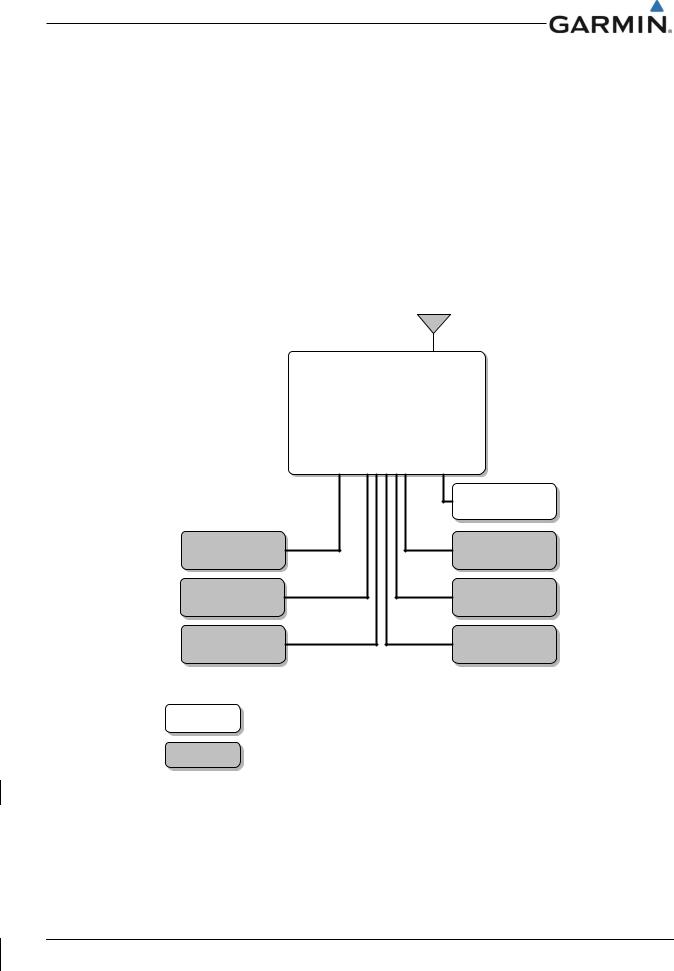
The GPS 175 is a panel-mounted 2” GPS Navigator. The GPS 175 features a capacitive touch-screen, full-color moving map display, power/home button, dual concentric rotary knob with push entry, SD card slot, and photo cell. The internal AHRS sensor cannot be used to drive anything other than the display of attitude on a non-certified PED. The built in Bluetooth allows for flight plan I/O and GPS position interface with a PED (Database concierge only available through Flight Stream 510). The GPS 175 is capable of providing TSO-C146e compliant GPS/WAAS navigation for en route, terminal, non-precision and precision capabilities (LPV) when interfaced with a CDI. The GPS 175 is also a certified ADS-B Out position source. The bezel of the GPS 175 is 2 inches x 6.25 inches and is designed to fit in the same location as older 2 inch avionics, such as GNC 255 or GTR 225.
GPS
Antenna
GPS 175
|
FS 510 |
|
(Optional) |
Display |
OBS Resolver |
Autopilot |
Discretes |
CDI |
GTX 345 or GDL 88 |
Legend |
|
Installed per |
|
this STC |
|
Existing |
|
Equipment |
|
Figure 2-1 GPS 175 System Diagram
190-02207-A2 |
GPS 175/GNX 375/GNC 355 Part 23 AML STC Maintenance Manual |
Rev. 2 |
Page 2-1 |
2.1.2 GNX 375
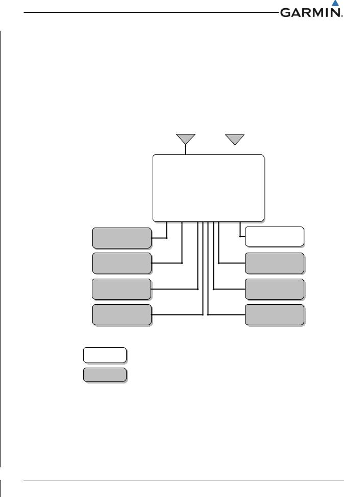
The GNX 375 is a panel-mounted 2” GPS Navigator and Transponder. The GNX 375 features a capacitive touch-screen, full-color moving map display, power/home button, dual concentric rotary knob with push entry, SD card slot, and photo cell. The GNX 375 has the same capabilities as the GPS 175, but has a Mode S transponder and ADS-B receiver. The internal AHRS sensor cannot be used to drive anything other than the display of attitude on a non-certified PED. The built in Bluetooth will allow flight plan I/O, GPS position, and ADS-B Weather/Traffic interface with a PED but will not allow software or database loading. The GPS navigation function is capable of providing TSO-C146e compliant GPS/WAAS navigation for en route, terminal, non-precision and precision capabilities (LPV) when interfaced with a CDI. The bezel of the GNX 375 is 2 inches x 6.25 inches and is designed to fit in the same location as older 2 inch avionics, such as GTX 327.
Transponder |
|
GPS |
Antenna |
|
Antenna |
|
||
|
|
|
GAE 12 |
GNX 375 |
|
(Optional) |
||
|
|
FS 510 |
|
(Optional) |
Display |
OBS Resolver |
Autopilot |
Discretes |
CDI |
Audio Panel |
Legend |
|
Installed per |
|
this STC |
|
Existing |
|
Equipment |
|
Figure 2-2 GNX 375 System Diagram
190-02207-A2 |
GPS 175/GNX 375/GNC 355 Part 23 AML STC Maintenance Manual |
Rev. 2 |
Page 2-2 |
2.1.3 GNC 355
The GNC 355 is a panel-mounted 2” GPS Navigator and COM radio. The GNC 355 features a capacitive touch-screen, full-color moving map display, power/home button, dual concentric rotary knob with push entry, SD card slot, and photo cell. The GNC 355 has the same capabilities as the GPS 175, but has a VHF COM radio. The GNC 355 has a 25 KHz spacing radio and the GNC 355A has a 8.33 KHz spacing radio. The internal AHRS sensor cannot be used to drive anything other than the display of attitude on a non-certified PED. The built in Bluetooth will allow flight plan I/O, GPS position, and ADS-B Weather/Traffic interface with a PED but will not allow software or database loading. The GPS navigation function is capable of providing TSO-C146e compliant GPS/WAAS navigation for en route, terminal, nonprecision and precision capabilities (LPV) when interfaced with a CDI. The bezel of the GNC 355 is 2 inches x 6.25 inches and is designed to fit in the same location as older 2 inch avionics, such as GNC 255 or GTR 225.
COM |
|
GPS |
Antenna |
|
Antenna |
|
||
|
|
|
GNC 355( )
Audio Panel |
FS 510 |
|
(Optional) |
||
|
||
Display |
OBS Resolver |
|
Autopilot |
Discretes |
|
CDI |
GTX 345 or GDL 88 |
|
Legend |
|
|
Installed per |
|
|
this STC |
|
|
Existing |
|
|
Equipment |
|
|
Figure 2-3 GNC 355 System Diagram |
|
190-02207-A2 |
GPS 175/GNX 375/GNC 355 Part 23 AML STC Maintenance Manual |
Rev. 2 |
Page 2-3 |
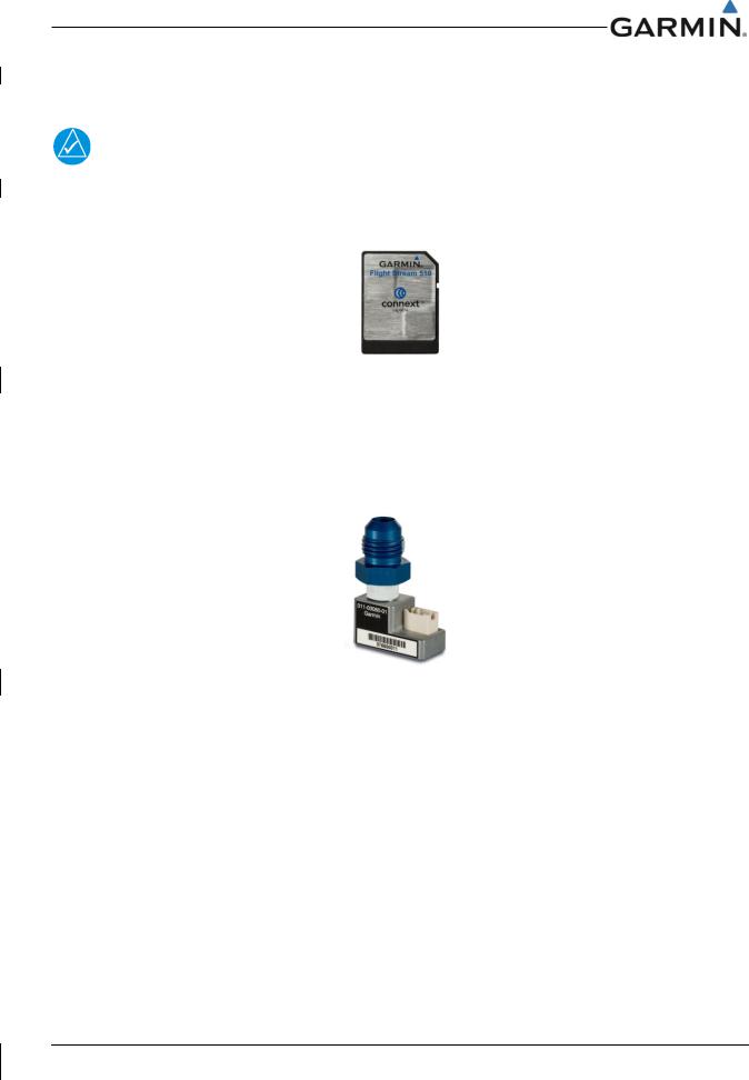
2.1.4 Flight Stream 510
NOTE
The Flight Stream 510 is a wireless-enabled data card that is inserted into the SD card slot.
The Flight Stream 510 interfaces to the GPS 175/GNX 375/GNC 355 by replacing the front-loaded data card to allow wireless database transfer with PEDs over Wifi.
Figure 2-4 Flight Stream 510
2.1.5 GAE 12
The GNX 375 allows for the use of an optional GAE 12 module as a transponder pressure altitude input. The GAE 12 module directly attaches to the GNX 375 backplate and connects to the aircraft static pressure system. The GAE 12 module replaces and functions the same as the configuration module.
Figure 2-5 GAE 12
190-02207-A2 |
GPS 175/GNX 375/GNC 355 Part 23 AML STC Maintenance Manual |
Rev. 2 |
Page 2-4 |
3.CONTROL AND OPERATION
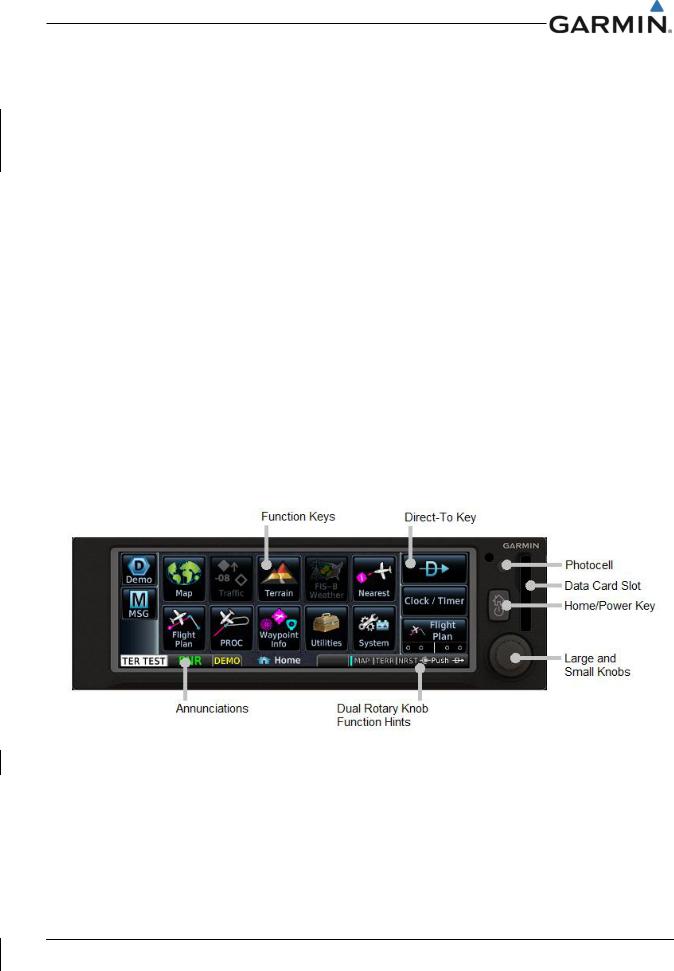
Control and operation of the GPS 175, GNX 375, and GNC 355 units occurs through the use of the touch display, dual rotary knob, and the home/power key. The Home page, seen below in Figure 3-1, Figure 3-2 and Figure 3-3, is the first page displayed after the startup prompts. All functions of the GPS 175/GNX 375/GNC 355 can be accessed through the Home page. At any time, the Home/Power key can be pressed to return to the Home page.
3.1GPS 175
The GPS 175 Home page is shown below in Figure 3-1. The figure below also contains labels identifying key aspects of the GPS 175 features and controls. These features and controls are as follows:
•Function Keys - Touch the function keys to access the features or pages described on the key.
•Direct-To Key – This key is used to initiate and activate navigation to a waypoint.
•Annunciations - The area of the screen displays annunciations to the pilot.
•Photocell – The photocell may be configured to be used by the display to automatically adjust the display backlighting with no further prompt.
•Data Card Slot - A card slot in the unit that accepts standard SD cards, Loader cards, and Flight Stream 510.
•Home/Power Key – This key can be pressed once to return to the Home page at any time, or can be held down to power off the unit.
•Large and Small Knobs – Control knobs that can be used to scroll through selections or various options on the display. Pressing the inner knob acts as an enter or selection of the currently highlighted information.
•Dual Rotary Knob Function Hints - This area of the screen provides more detailed information on the operation of the dual concentric knobs for the given page.
Figure 3-1 GPS 175 Home Page
190-02207-A2 |
GPS 175/GNX 375/GNC 355 Part 23 AML STC Maintenance Manual |
Rev. 2 |
Page 3-1 |
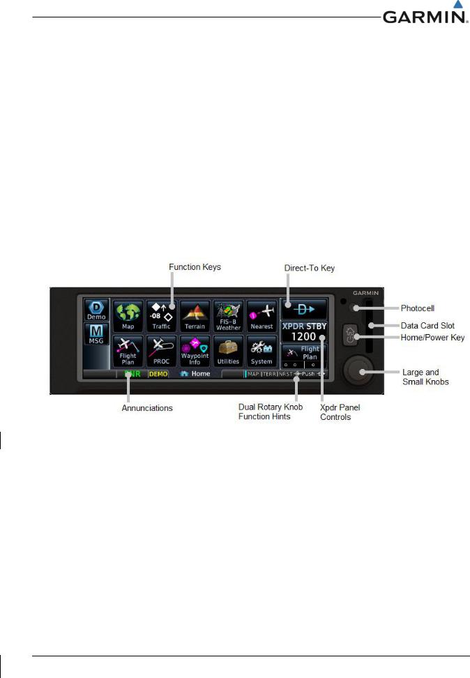
3.2GNX 375
The GNX 375 Home page is shown below in Figure 3-2. The figure below also contains labels identifying key aspects of the GNX 375 features and controls. These features and controls are as follows:
•Function Keys - Touch the function keys to access the features or pages described on the key.
•Direct-To Key – This key is used to initiate and activate navigation to a waypoint.
•XPDR Panel Controls – This key is used to access transponder functions and modes.
•Annunciations - The area of the screen displays annunciations to the pilot.
•Photocell – The photocell may be configured to be used by the display to automatically adjust the display backlighting with no further prompt.
•Data Card Slot - A card slot in the unit that accepts standard SD cards, Loader cards, and Flight Stream 510.
•Home/Power Key – This key can be pressed once to return to the Home page at any time, or can be held down to power off the unit.
•Large and Small Knobs – Control knobs that can be used to scroll through selections or various options on the display. Pressing the inner knob acts as an enter or selection of the currently highlighted information.
•Dual Rotary Knob Function Hints - This area of the screen provides more detailed information on the operation of the dual concentric knobs for the given page.
Figure 3-2 GNX 375 Home Page
190-02207-A2 |
GPS 175/GNX 375/GNC 355 Part 23 AML STC Maintenance Manual |
Rev. 2 |
Page 3-2 |
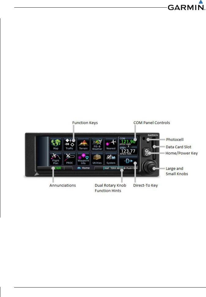
3.3GNC 355
The GNC 355 Home page is shown below in Figure 3-3. The figure below also contains labels identifying key aspects of the GNC 355 features and controls. These features and controls are as follows:
•Function Keys - Touch the function keys to access the features or pages described on the key.
•Direct-To Key – This key is used to initiate and activate navigation to a waypoint.
•COM Panel Controls – This key is used to access the COM radio frequencies and functions.
•Annunciations – The area of the screen displays annunciations to the pilot.
•Photocell – The photocell may be configured to be used by the display to automatically adjust the display backlighting with no further prompt.
•Data Card Slot - A card slot in the unit that accepts standard SD cards, Loader cards, and Flight Stream 510.
•Home/Power Key – This key can be pressed once to return to the Home page at any time, or can be held down to power off the unit.
•Large and Small Knobs – Control knobs that can be used to scroll through selections or various options on the display. Pressing the inner knob acts as an enter or selection of the currently highlighted information.
•Dual Rotary Knob Function Hints - This area of the screen provides more detailed information on the operation of the dual concentric knobs for the given page.
Figure 3-3 GNC 355 Home Page
190-02207-A2 |
GPS 175/GNX 375/GNC 355 Part 23 AML STC Maintenance Manual |
Rev. 2 |
Page 3-3 |
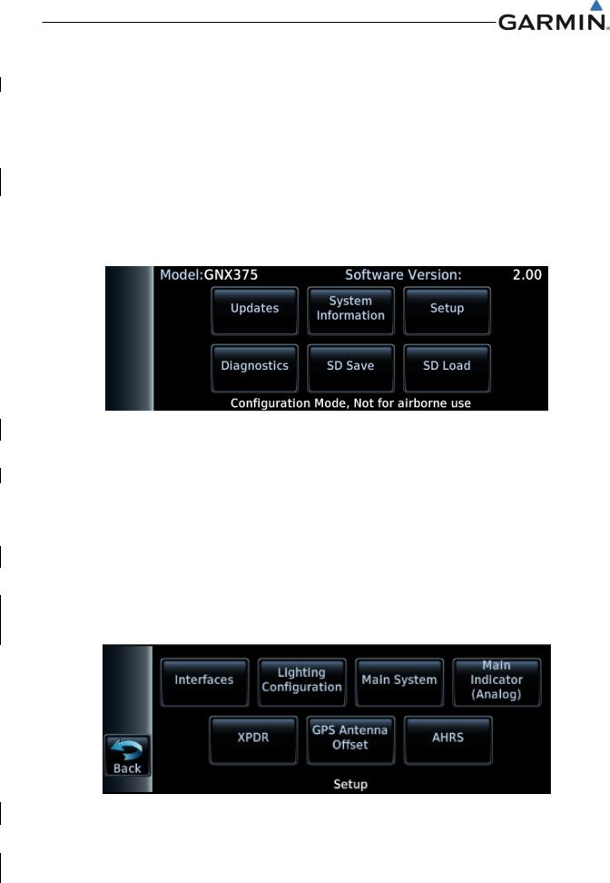
3.4Configuration Mode Overview
Configuration mode is used to configure the GPS 175/GNX 375/GNC 355 settings for each specific installation. To access Configuration mode, hold down the inner knob and press the power/home button. When the configuration mode home page appears as shown below, release the knob.
The Configuration Mode page is the first page that is displayed in this mode. For detailed information regarding how to configure the GPS 175, refer to GPS 175 Part 23 AML STC Installation Manual. For detailed information regarding how to configure the GNX 375, refer to GNX 375 Part 23 AML STC Installation Manual. For detailed information regarding how to configure the GNC 355, refer to GNC 355 Part 23 AML STC Installation Manual. While in configuration mode, different pages can be selected by touching the desired key on the display. Some pages may require scrolling to view all of the information an keys. Scrolling pages are indicated by a series of dots along the bottom of the page, and scrolling is done by touching the screen and dragging the page in the desired direction.
Figure 3-4 Configuration Mode Home Screen
3.4.1 Updates
The Software Updates page allows the user to update the GPS 175/GNX 375/GNC 355 software versions. For more information on software updates and instructions see Section 7.2.
3.4.2 System Information
The System Information page displays general and board specific information for the GPS 175/GNX 375/GNC 355. This page is used when checking for software versions as described in Section 7.1.
3.4.3 Setup
This section provides a brief overview of the pages that are accessed from the GPS 175/GNX 375/GNC 355 Setup page. To access the GPS 175/GNX 375/GNC 355 Setup page, touch the Setup key from the Configuration Mode page, as shown in Figure 3-4.
|
Figure 3-5 GNX 375 Setup Page |
|
|
190-02207-A2 |
GPS 175/GNX 375/GNC 355 Part 23 AML STC Maintenance Manual |
Rev. 2 |
Page 3-4 |

3.4.3.1 Interfaces
The Interfaced Equipment page allows for the configuration of the various input and outputs that support interfaces to the GPS 175/GNX 375/GNC 355.
3.4.3.1.1 ARINC 429
The Interfaced Equipment – ARINC 429 page allows the configuration of data formats and speeds of ARINC 429 inputs and outputs.
3.4.3.1.2 RS-232 (RS-422)
The Interfaced Equipment – RS–232 / RS–422 page allows the configuration of data formats for both
Port 1 and Port 2.
•Port 1 is capable of operating as either an RS-232 port or an RS-422 port.
•Port 2 is only capable of operating as an RS-232 port.
3.4.3.1.3 GDU
The GDU toggle key indicates whether or not a GDU is Present or Not Present in the installation.
3.4.3.2 Lighting Configuration
The Lighting Configuration page allows the user to configure the backlight and key lighting brightness display parameters. This page also allows the configuration of the photocell and the lighting bus settings.
3.4.3.3 Main System
The Main System allows the user to configure system related settings for the GPS 175/GNX 375/GNC 355. Page settings include the following:
• |
Air/Ground Threshold |
• |
Terrain Alerts |
• |
Fuel Type |
• |
Graphical Edit |
• |
GPS Select |
• |
Composite CDI |
• |
System ID |
• |
Bluetooth |
• |
RF Procedure Legs |
• ADS-B Logging (GNX 375 Only) |
|
• |
Ownship Icon |
• |
External FPL |
3.4.3.4 Main Indicator (Analog)
The Main Indicator (Analog) page allows the user to calibrate the OBS resolver and configure the selected course behavior.
3.4.3.5 XPDR (GNX 375 Only)
The XPDR Configuration page allows the user to configure the transponder related settings for the GNX 375. Page settings include the following:
• |
Sensors |
• |
Airframe |
• |
Options |
• |
Flight ID |
• |
Test |
• |
Clear XPDR Settings |
3.4.3.6 GPS Antenna Offset
The GPS Antenna Offset page allows the configuration of GPS antenna height, lateral offset, and longitudinal offset.
190-02207-A2 |
GPS 175/GNX 375/GNC 355 Part 23 AML STC Maintenance Manual |
Rev. 2 |
Page 3-5 |

3.4.3.7 AHRS
The AHRS page allows the user to set the display orientation, yaw offset, and calibrate the internal AHRS. The Display Orientation must be set and the aircraft must be level before calibrating the internal AHRS.
3.4.3.8 COM (GNC 355 only)
The COM page allows the user to select and configure squelch mode, configure carrier squelch, configure MIC gain, select sidetone source and configure the volume.
3.4.4 Diagnostics
The Diagnostics page provides access to pages that are helpful for unit maintenance and troubleshooting. Ground checks are performed using the tools on this page. The following pages are accessible within the Diagnostics page:
• |
ARINC Inputs |
• |
Main Indicator |
• |
WAAS |
• |
Serial Inputs |
|
(Analog) |
• |
Temps |
• |
Discrete Inputs |
• |
Composite Indicator |
• |
Logs |
• |
Discrete Outputs |
• |
Analog Inputs |
• |
Main Data Inputs |
• |
HSDB Ethernet |
• |
Gillham Encoder |
• |
XPDR Main Data |
• |
XPDR (GNX 375 |
|
(GNX 375 Only) |
|
(GNX 375 Only) |
|
Only) |
• |
Power Stats |
• |
Clear Config Settings |
3.4.4.1 ARINC Inputs
This page displays the ARINC 429 data that is being received over each ARINC 429 port. Each port is chosen for display by touching the ARINC 429 Port key to toggle between the input ports. Select a port to display. The GPS 175/GNX 375/GNC 355 will then display the label, SSM, Data, and SDI for each ARINC 429 packet received by the selected port. This is useful for determining if the expected labels are being received and for troubleshooting incorrect or swapped wiring to the input ports. The data log can be paused/resumed by touching the Pause key. The displayed data log can be cleared by touching the
Clear Log key.
3.4.4.2 Serial Inputs
This page displays the status of each serial data port. For each serial port, the status will say either Not Configured, Receiving, or Not Receiving. This data is useful for determining if the serial data ports are configured and operating as intended.
3.4.4.3 Discrete Inputs
This page displays the state of each of the discrete input pins on the GPS 175/GNX 375/GNC 355. For each discrete input, the pin number, pin function and pin active state are shown. This page is useful for diagnosing and troubleshooting discrete wiring issues.
3.4.4.4 Discrete Outputs
This page displays the state of each of the discrete outputs on the GPS 175/GNX 375/GNC 355. This page also allows for the discrete outputs to be toggled between the Active and Inactive states. This is useful for ensuring that these signals output are properly connected to annunciator lights, or other LRUs, and that they are receiving the signal.
3.4.4.5 HSDB Ethernet
This page displays the status of the HSDB ethernet port and the status of any LRUs that are interfaced to the GPS 175/GNX 375/GNC 355 via HSDB. The ethernet port will display either Not Configured, Receiving, or Not Receiving. For each LRU (GDU/GDL 88/GTX 345), the page will display either Online or Offline.
190-02207-A2 |
GPS 175/GNX 375/GNC 355 Part 23 AML STC Maintenance Manual |
Rev. 2 |
Page 3-6 |

3.4.4.6 XPDR (GNX 375 Only)
The GNX 375 monitors internal systems to verify functionality. Errors are displayed as Pilot Alerts, Failures, Faults, and Warnings. Failures are the most severe, followed by Faults, Warnings, then pilot alerts. This page allows the user to view the status of all failure conditions, active faults, active warnings, and associated pilot alerts. For troubleshooting of these errors see the XPDR Alert Troubleshooting flowcharts start at Figure 5-6.
3.4.4.7 Main Indicator (Analog)
This page displays the status of the analog deviation and flag outputs to the CDI. These can be changed and the output viewed on the CDI for the purpose of performing ground checks on the analog CDI interface.
3.4.4.8 Composite Indicator
This page displays the status of the composite deviation and vertical/lateral flag outputs to the CDI. These can be changed and the output viewed on the CDI for the purpose of performing ground checks on the composite CDI interface.
3.4.4.9 Analog Inputs
This page displays the lighting bus voltages for Bus Setting and Input Voltage.
3.4.4.10 Gillham Encoder (GNX 375 Only)
The Gillham Diagnostics page displays the status and discrete pin settings for the Gillham altitude input.
3.4.4.11 Power Stats
This page displays the number of times the GPS 175/GNX 375/GNC 355 has powered up and the total elapsed operating hours for the GPS 175/GNX 375/GNC 355.
3.4.4.12 WAAS
This page displays the WAAS engine status, including UTC date/time, current latitude/longitude, and navigation status. This page also allows the GPS/WAAS engine to be reset.
3.4.4.13 Temps
This page displays the current, minimum, maximum, and average temperatures for the processor, display, and LED boards.
3.4.4.14 Logs
This page allows for the export and clearing of the error log, maintenance log, ADS-B data log (GNX 375 only) and WAAS data log. The Clear Log key removes all messages from the selected log and the Save to SD Card key saves the selected information to the SD card.
3.4.4.15 Main Data Inputs
The Main Data Inputs page displays ARINC 429, RS-232, and other electrical inputs information. Data not received is dashed out. The page aids in verifying electrical interfaces during installation and troubleshooting.
3.4.4.16 XPDR Main Data (GNX 375 Only)
This page provides the user access to the GPS Data Diagnostics and Air Data Diagnostics pages.
190-02207-A2 |
GPS 175/GNX 375/GNC 355 Part 23 AML STC Maintenance Manual |
Rev. 2 |
Page 3-7 |
3.4.4.17 Clear Config Settings
To reset the unit to the original factory configuration values, tap Clear Config Settings > OK. Then restart the unit.
3.4.5 SD Save
SD Save exports the configuration to an SD card. This allows specific airframe configuration information to be loaded to a difference unit. Use the following instructions to save the configuration information to an SD card:
1.Insert an SD card into the card slot.
2.Power on the unit in configuration mode.
3.Touch the SD Save key.
4.Tap OK to acknowledge a successful export.
3.4.6SD Load
SD Load allows a previously saved configuration to be loaded from an SD card. The System ID and software version must match the unit saved to the card. Before configuring, determine if a previously saved configuration is available. Use the following instructions to load the saved configuration information to a unit:
1.Power the unit on in configuration mode.
2.Insert SD card into the card slot.
3.Tab SD Load.
4.Tap a file to load.
5.Restart the unit.
6.Verify settings on Interface Settings page are correct.
190-02207-A2 |
GPS 175/GNX 375/GNC 355 Part 23 AML STC Maintenance Manual |
Rev. 2 |
Page 3-8 |


4.2Servicing Information
The GPS 175, GNX 375 and GNC 355 do not require servicing. In the event of system failure, troubleshoot the GPS 175/GNX 375 in accordance with Section 5.
4.2.1 Periodic Maintenance
The GPS 175/GNX 375/GNC 355 are designed to detect internal failures. A thorough self-test is executed automatically upon application of power to the units. The built-in tests (BIT) are continuously executed. Detected errors are indicated as failure annunciations, system messages or a combination of the two.
Antenna installations are not covered under this STC. Inspect and maintain all antennas in accordance with the data provided for that specific antenna installation.
4.2.2 Special Tools
A milliohm meter with an accuracy of ±0.1 mΩ (or better) is required to measure the electrical bonding between the GPS 175/GNX 375/GNC 355 system components and aircraft ground.
190-02207-A2 |
GPS 175/GNX 375/GNC 355 Part 23 AML STC Maintenance Manual |
Rev. 2 |
Page 4-2 |
 Loading...