


500W Series
Quick
Reference
|
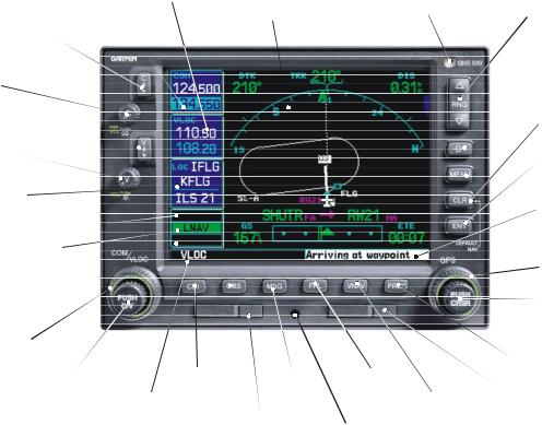
Nav Freq |
Graphic Moving |
|
Com Freq |
Window |
||
Map Display and |
|||
Window |
|
||
|
Navigation Info |
||
|
|
Comm Freq Flip/Flop
Power and Com
Volume/Squelch
Nav Radio Freq Flip/Flop
Nav Radio Volume
Localizer ID
and Runway
Terrain Annunciator
Flight Phase Annunciator
GPS Integrity Annunciator
Large Knob |
|
|
Com/VLOC Freq |
|
|
(MHz) |
KeyCDI |
|
Small Knob |
OBS |
|
Com/VLOC |
Navigation |
Key Key |
Freq (kHz) |
Source: GPS, |
Aviation |
|
||
|
VLOC, or |
|
|
Database |
|
|
GPS-PTK |
|
|
Data Card |
|
|
|
Photocell |
|
for Auto- |
|
Dimming |
Range Keys |
|
|
Direct-To Key |
|
|
|
Menu Key |
|
|
|
Clear Key |
|
|
|
Enter Key |
|
|
|
Waypoint and |
|
|
|
arrival alerts, |
|
|
|
turn advisories, |
|
|
|
function, and |
|
|
|
page number |
|
|
|
Large Knob |
|
|
|
Small Knob |
|
|
|
(Cursor - Press |
|
|
|
to activate) |
|
|
|
Procedure Key |
|
Key |
|
Terrain Database |
|
VNAV Key |
Data Card |
||
|
|||
Cam Lock |
|
|

MODEL DESCRIPTIONS
Model Descriptions
This guide covers the operation of the GNS 530W, GNS 530AW, and the GPS 500W. In general, all models will be referred to as the 500W-series, except where there are physical or operational differences. The 500W-series units are 6.25” wide and 4.60” high. The display is a 320 by 234 pixel color LCD. The units include two removable data cards, one with a Jeppesen aviation database (inserted in the left-most card slot) and the second is a Terrain database (inserted in the right-most card slot).
GPS 500W
The GPS 500W is a GPS-only unit with a WAAS GPS engine and is TSO C146a certified for en route, terminal, precision, and non-precision approaches. The GPS 500W can simultaneously give aviators vital approach information and weather and traffic data in relation to their position on a large, color moving map display. Thanks to a high-contrast color display, the information can be easily read from wide viewing angles even in direct sunlight. Its color moving map features a built-in database that shows cities, highways, railroads, rivers, lakes, coastlines, and a complete Jeppesen aviation database. The Jeppesen database (that can be updated with a front-loading data
card) contains all airports, VORs, NDBs, Intersections, FSS, Approach, DPs/STARs and SUA information. The obstacle and terrain databases provide an aid to navigation to help you work with approved navigation charts.
Pilots will enjoy the GPS 500W as an Multi-Function Display (MFD), especially when it is coupled with traffic, lightning detection, and weather interfaces like Ryan TCAD, TIS from the Garmin GTX 330 Mode S transponder, L3 SKYWATCH™, or STORMSCOPE® WX 500. With the Fault Detection and Exclusion (FDE) prediction program included with the Trainer CD, the GPS 500W may be used for oceanic or remote operations. For the latest in graphical and textual weather information, the GPS 500W can con-
nect to XM Satellite Radio’s XM WX Weather Service via the GDL 69 datalink receiver plus XM Audio with the
GDL 69A.
GNS 530W and GNS 530AW
The GNS 530W and GNS 530AW include all of the features of the GPS 500W, and also include an IFR certified airborne VHF communications transceiver and IFR certified airborne VOR/Localizer and Glideslope receivers. This multi-purpose unit is available with either a 10-watt (GNS 530W) or 16-watt (GNS 530AW) Com transceiver. References to the GNS 530W also include the GNS 530AW.
1
KEYS AND KNOBS
Left-hand Keys and Knobs
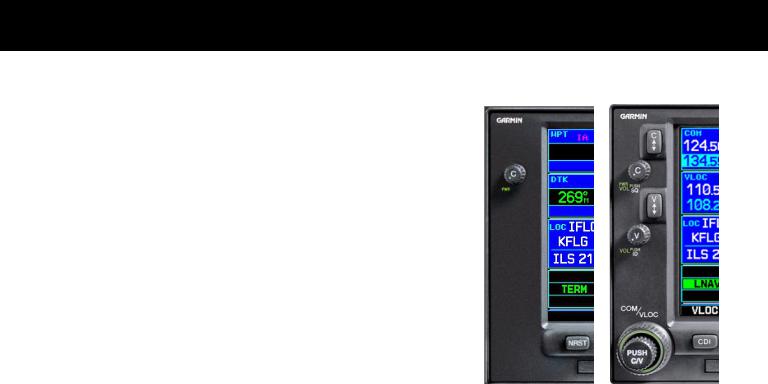
kThe COM power/volume knob controls unit power and, in the GNS 530W, communications radio volume. Press momentarily to disable automatic squelch control. Turn clockwise to turn the unit on.
jIn the GNS 530W, the VLOC volume knob controls audio volume for the selected VOR/ Localizer frequency. Press momentarily to enable/disable the ident tone.
In the GNS 530W, the large left knob (COM/VLOC) is used to ytune the megahertz (MHz) value of the standby frequency for the communications transceiver (COM) or the VOR/Localizer receiver,
whichever is currently selected by the tuning cursor.
vIn the GNS 530W, the small left knob (PUSH C/V) is used to tune the kilohertz (kHz) value of the standby frequency for the communications transceiver (COM) or the VLOC receiver, whichever is currently selected by the tuning cursor. Press this knob momentarily to toggle the tuning cursor between the COM and VLOC frequency fields.
WIn the GNS 530W, the COM flip-flop key is used to swap the active and standby COM frequencies. Press and hold to select the emergency channel (121.500 MHz).
VIn the GNS 530W, the VLOC flip-flop key is used to swap the active and standby VLOC frequencies
(i.e., make the selected standby frequency active).
GPS 500W |
GNS 530W |
On the GNS 530W, the large and small left knobs allow you to tune the desired COM or VLOC frequency.
2
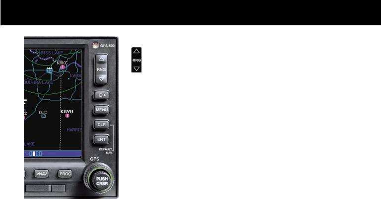
Data is entered using the large and small right knobs. Experiment with them to become efficient at entering data.This greatly reduces the amount of time spent operating the 500W-series
unit in flight.
KEYS AND KNOBS
Right-hand Keys and Knobs
The range key (RNG) allows you to select the desired map scale. Press the up arrow to zoom out to a larger area, or the down arrow to zoom in to a smaller area.
DThe direct-to key provides access to the direct-to function, which allows you to enter a destination waypoint and establishes a direct course (singleleg flight plan) to the selected destination.
mThe menukey (MENU) displays a context-sensitive list of options. This options list allows you to access additional features or make settings changes which relate to the currently displayed page.
cThe clear key (CLR) is used to erase information or cancel an entry. Press and hold this key to immediately display the Default Navigation Page, regardless of which page is currently displayed.
EThe enter key (ENT) is used to approve an operation or complete data entry. It is also used to confirm information, such as the Database Page during power on.
tgroups: NAV, WPT, AUX or NRST. With the on-screen cursor enabled, the large right knob allows you to move the cursor about the page.The large right knob (GPS) is used to select between the various page
rThe small right knob (PUSH CRSR) is used to select between the various pages within one of the groups listed above. Press this knob momentarily to display the on-screen cursor. The cursor allows you to enter data and/or make a selection from a list of options.
3
KEYS
GPS 500W
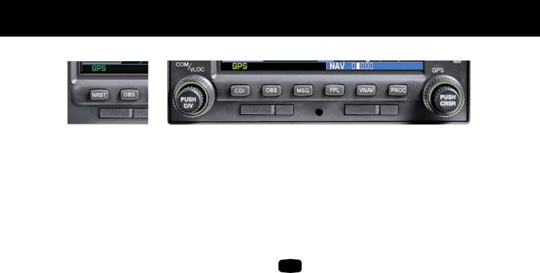
Bottom Row Keys
NThe nearest (NRST) key (GPS 500W) displays the Nearest Airports page. Then, turning the small right knob steps through the NRST pages.
CThe course deviation indicator (CDI) key (GNS 530W) is used to toggle the navigation source (GPS or VLOC) that provides output to an external HSI or CDI.
OThe omni-bearing selector (OBS) key is used for two functions: to activate OBS selection and as a suspend key.
As a Suspend key, it is used to select manual or automatic sequencing of waypoints. Pressing this key selects SUSP mode, which retains the current “active to” waypoint as your navigation reference even after passing the waypoint (i.e., prevents sequencing to the next waypoint). Pressing the OBS key again returns to normal operation, with automatic sequencing of waypoints.
Whenever OBS mode is selected, you may set the desired course to/from a waypoint using the OBS Page, or an external OBS selector on your HSI or CDI.
GNS 530W
MThe message (MSG) key is used to view system messages, important warnings, and requirements.
FThe flight plan (FPL) key allows you to create, edit, activate and invert flight plans, as well as access approaches, departures and arrivals. A closest-point-to-flight-plan feature is also available from the flight plan key.
VNAV |
The vertical navigation (VNAV) key allows |
|
you to create a three-dimensional profile |
||
|
||
|
which guides you to a final (target) altitude at |
|
|
a specified location. |
PThe procedures (PROC) key allows you to select approaches, departures and arrivals from your flight plan. When using a flight plan, available procedures for your departure and/or arrival airport are offered automatically. Otherwise, you may select the desired airport, then the desired procedure.
4

POWER ON
Powering Up
1.Turn the COM power/volume knob clockwise to turn the unit on and set the desired radio volume.
2.The Main and GPS software version page appears briefly,followedbylandandterraindatabasepages, as the unit conducts self-tests to ensure proper operation.
3.Once the self-test concludes, database confirmation pages are displayed,showing the effective and expiration dates of the databases on the NavData® card. Press the ENT key to acknowledge the last databasepageandproceedtotheinstrumentpanel self-test page.There may be more self-test screens depending on optional equipment installed in your aircraft.
4.The instrument panel self-test page allows you to verify that the unit is communicating properly with in-panel instruments. Compare on-screen indications with the information depicted on connected instruments,such as the CDI,HSI,RMI and/or external annunciators. Once you have verified proper operation, turn the large right knob to select "Set Full Fuel?", "Go To Checklist", or "OK?" (to display the Satellite Status Page), and then press the ENT key. Other pages may exist depending on the installation of optional features.
5.When the GPS receiver has acquired a sufficient number of satellites to determine a position, the Map Page is automatically displayed showing your present position.
Power-up Sequence
5
 Loading...