


 Loading...
D-Link DI-704P
Express Ethernetwork TM Broadband Router with Print Server
Manual
Building Networks for People
Contents |
|
Package Contents ................................................................................ |
3 |
Introduction............................................................................................ |
4 |
Features and Benefits ........................................................................... |
5 |
LEDs .................................................................................................... |
6 |
Connections .......................................................................................... |
7 |
Introduction to Broadband Technology ................................................... |
8 |
Sample Scenario ................................................................................ |
10 |
Network Setup .................................................................................... |
11 |
Setup Wizard ...................................................................................... |
12 |
Using the Configuration Menu.............................................................. |
17 |
Networking Basics .............................................................................. |
62 |
Reset .................................................................................................. |
90 |
Technical Specifications ...................................................................... |
91 |
Contacting Technical Support .............................................................. |
92 |
Warranty and Registration ................................................................... |
93 |
2
Package Contents
Contents of Package:
!D-Link DI-704P Express EtherNetworkTM
Broadband Router
!Manual, Warranty and Print Server Software on CD
!Quick Installation Guide
!Power Adapter - 5V DC
!Ethernet (CAT5-UTP/Straight-Through) Cable
If any of the above items are missing, please contact your reseller.
WARNING! Using a power supply with a different voltage rating than the one included with the DI-704P will cause damage and void the warranty for this product.
System Requirements for Configuration:
!Ethernet-based Cable or DSL Modem
!Computer with Windows, Macintosh, or Linux-based Operating System with an installed Ethernet adapter
!Internet Explorer version 6.x or Netscape Navigator
version 6.x and above, with Javascript enabled
3
Introduction
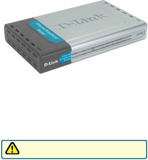
Thank you for purchasing DI-704P 4-Port Ethernet Broadband Router. The DI704P is an Ethernet Broadband Router with a built-in 4-port switch. It also features a parallel port to share a printer on the home or office network and includes a print server application for Windows1. As many as four computers can be connected directly to the router’s integrated switch, using its four 10/100Mbps AutoMDIX Ethernet ports. More computers can be added to the network by connecting additional switches to the DI-704P. The DI-704P package even includes an Ethernet cable to get you started.
The DI-704P is ideal if you’re creating your first home or small business network, or if you’re a more advanced user looking for additional management settings.
The DI-704P includes a new, easy-to-use D-Link web-based graphical user interface (GUI) to configure the router. To prevent unwanted Internet intruders from accessing your private network, the DI-704P also serves as a feature-rich firewall.
So, whether you’re a college student who wants to network with friends and roomates, an executive working at home or in a small office, or a concerned parent who just wants to have more control over how your children access the Internet, then the D-Link Express EtherNetwork DI-704P is the networking solution for you.
1Print Server software included is for Windows Operating Systems only. Postscript Level 1 and 2 printers can be connected to the DI-704P for Macintosh OS 9.x or X computers. The DI-704P does not support non-Postscript printers with Macintosh OS. 4
Features & Benefits
!Firewall Features
!Filtering - Easily applied filtering based on Media Access Control (MAC) Addresses, IP Addresses, Port Addresses, and time schedule allows or denies computer on the network access to the Internet.
!Network Address Translation - NAT allows your private network to share a single public IP address. All your computer connected to the DI-704P will be on a private network shielded from Internet intruders.
!Built-In 4-Port Switch - Allows you to quickly and easily share an Internet connection with multiple computers and devices. Each 10/ 100 Ethernet Port automatically senses and accepts the type of Category (CAT) 5 cable you attach - whether straight through or cross-over. Connect additional switches to allow more computer to access the Internet.
!Built-In Print Server - Includes a parallel port to connect to a centronic printer and includes a Windows-based print server software application, so users on the network can share the printer1. The print server is also capable of TCP/IP printing.
!Ethernet Cable Included - One Ethernet cable is included with the DI-704P to get you started.
!Simple Setup Wizard for Easy Installation - The D-Link setup wizard simplifies the installation process, getting you up and running in just a few clicks.
1Print Server software included is for Windows Operating Systems only. Postscript Level 1 and 2 printers can be connected to the DI-704P for Macintosh OS 9.x or X computers. The DI-704P does not support non-Postscript printers with Macintosh OS. 5
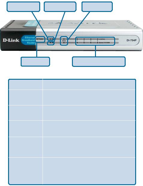
LEDs
M1 LED |
M2 LED |
WAN LED |
POWER LED |
LOCAL NETWORK LEDs |
LED |
LED Activity |
|
Power |
A solid light indicates a proper connection to |
|
|
the power supply. |
|
M1 LED |
Flashes consistently to indicate that the |
|
DI-704P is working properly. |
||
|
||
M2 LED |
Solid light indicates that Internet connec- |
|
tion has been established. |
||
|
||
WAN |
A Solid light indicates connection on the |
|
WAN port. This LED blinks during data |
||
|
transmission. |
|
LOCAL |
A solid light indicates a connection to an |
|
NETWORK |
||
Ethernet-enabled computer on ports 1-4. This |
||
LEDs |
||
LED blinks during data transmission |
||
(Ports 1-4) |
||
|
6
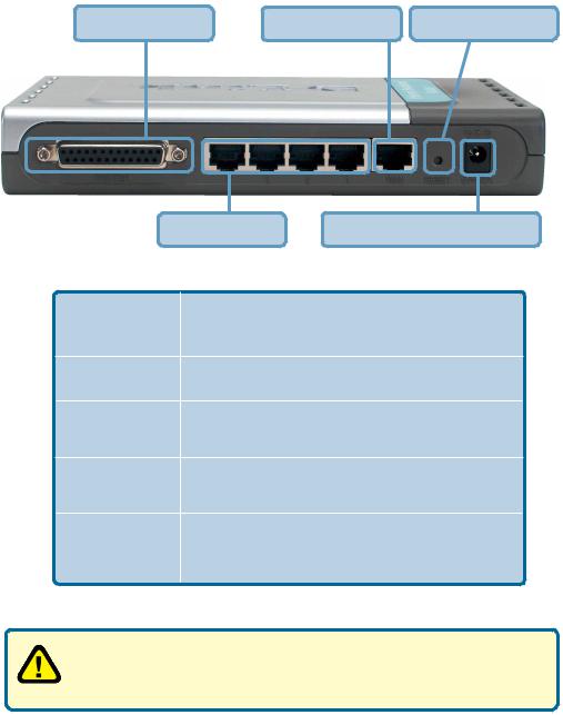
Connections
Printer Port |
WAN Port |
Reset Button |
LAN Ports |
Receptor for Power Adapter |
Receptor for |
Connect the supplied power adapter that came |
|
with the unit. Using the wrong power adapter will |
||
PowerAdapter |
||
damage the unit. |
||
|
||
Reset Button |
Reset button is to reset the device to its factory |
|
default settings. |
||
|
||
Printer Port |
Connect to the printer using a parallel cable. This |
|
feature is used to share the printer on the network. |
||
|
||
WAN Port |
WAN port is the connection point for your DSL or |
|
Cable modem. |
||
|
||
Lan Ports |
LAN port is where you would connect each |
|
computer to your network. |
||
|
||
|
|
WARNING!
Using a power supply with a different voltage rating than the one included with the DI-704P will cause damage and void the warranty for this product.
7
Introduction to Broadband
Router Technology
A router is a device that forwards data packets from a source to a destination. Routers can work on Open System Interconnection (OSI) layer 3, which forwards data packets using an IP address and not a MAC address. A router will forward data from the Internet to a particular computer on your LAN.
The information that makes up the Internet gets moved around using routers. When you click on a link on a wed page, you send a request to a server to show you the next page. The information that is sent and received from your computer is moved from your computer to the server using routers. A router also determines the best route that your information should follow to ensure that the information is delivered properly.
A router controls the amount of data that is sent through your network by eliminating information that shouldn’t be there. This provides security for the computers behind your router because computers from the outside cannot access or send information directly to any computer on your network. The router determines which computer the information should be forwarded to and sends it. If the information is not intended for any computer on your network, the data is discarded. This keeps any unwanted or harmful information from accessing or damaging your network.
Introduction to Firewalls
A firewall is a device that sits between your computer and the Internet that prevents unauthorized access to or from your network. A firewall can be a computer using firewall software or a special piece of hardware built specifically to act as a firewall. In most circumstances, a firewall is used to prevent unauthorized Internet users from accessing private networks suchs as corporate LANs and Intranets.
A firewall watches all of the information moving to and from your network and analyzes each piece of data. Each piece of data is checked against a set of criteria that the administrator configures. If any data does not meet the criteria, that data is blocked and discarded. If the data meets the criteria, the data is paased through.. This method is called packet filtering.
A firewall can also run specific security functions based on the type of application or type of port that is being used. For example, a firewall can be configured to work with an FTP or Telnet server. Or a firewall can be configured to work with specific UDP or TCP ports to allow certain applications or games to work
properly over the Internet. |
8 |
Introduction to Local Area Networking
Local Area Networking (LAN) is the term used when connecting several computers together over a small area such as a building or group of buildings. LAN’s can be connected over large areas. A collection of LANs connected over a large area is called a Wide Area Network (WAN).
A LAN is consists of multiple computers connected to each other. There are many types of media that can connect computers together. The most common media is CAT5 cable; UTP or STP twisted pair wire. Each computer must have a Network Interface Card (NIC), which communicates the data between computers. A NIC is usually a 10Mbps network card or 10/100Mbps network cards.
Most networks use hardware devices such as hubs or switches that each cable can be connected to in order to continue the connection between computers. A hub simply takes any data arriving through each port and forwards the data to all other ports. A switch is more sophisticated, in that a switch can determine the port that each piece of data is supposed to be delivered to. A switch minimizes network traffic and speeds up the communication over a network.
Networks take some time in order to plan and implement correctly. There are many types of scenarios to consider which could affect the operability of a network. Some of these issues are discussed in the manual under the
Networking Basics section.
9
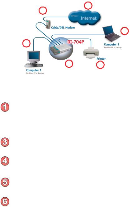
Sample Scenario
1
2
5
4
3 6
A typical network setup at home (as shown above) might contain the following devices. For specific information on setting up your network with the DI-704P please see the Network Setup section on the following page.
You will need broadband Internet access (a Cable or DSL subscription line into your home or office)
 Consult with your Cable or DSL provider for proper installation of the modem
Connect the Cable or DSL modem to the DI-704P wireless broadband router (see the Quick Installation Guide included with the DI-704P.)
If you are connecting a desktop computer to your network, you can install the D-Link DFE-530TX+ Ethernet adapter into an available PCI slot. (See the Quick Installation Guide included with the DWL-530TX+.)
If you are connecting a laptop computer to your network, install the drivers for the Ethernet Cardbus adapter (e.g., D-Link DFE-690TXD) into a laptop computer.(See the Quick Installation Guide included with the DFE-690TXD.)
Connect your printer to the printer port on the DI-704P. Please refer to the quick installation guide for loading the print server software.
** Easily upgrade to a wireless network by adding a wireless Access Point (D-Link DWL-900AP+) ** |
10 |
Network Setup
Turn everything off.
A.Power OFF your Cable or DSL modem. If you modem does not have an on/off switch, disconnect the power cable.
B.Turn OFF your computer.
C.Do NOT connect the power adapter to your D-Link router.
Connect the D-Link Router Cables.
A.Connect the Ethernet (or networking) cable from the Cable or DSL modem to the WAN port of the router.
B.Use the D-Link supplied Ethernet cable to connect the Ethernet port (Network Card) of your computer to one of the LAN ports of the router. The complete setup should look like Fig.1 shown above.
Power up the devices in sequence.
A. Power up the Cable or DSL modem. Wait until the modem has made the connection to your Internet Service Prover’s (ISP’s) network.
Note: Please see the Manual included with your modem for an explanation of the modem’s LEDs.
B.Power up the D-Link router by connecting the D-Link provided power adapter to the router and to an available power outlet.
C.Turn on your computer.
D.Now, refer to either the Quick Installation Guide or continue
to follow this manual to complete the installation process.
11
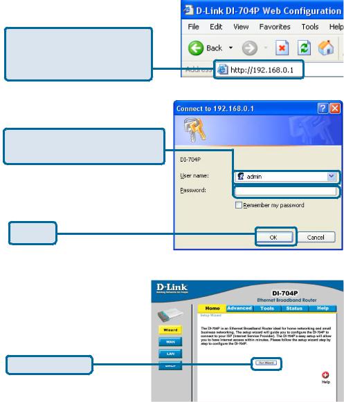
Using the Setup Wizard
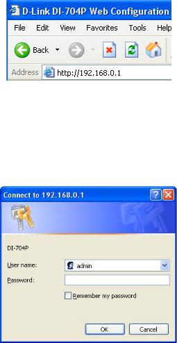
Open your Web browser and type “http://192.168.0.1” into the URL address box. Then press the
Enter or Return key.
The logon pop-up screen will appear.
Type “admin” for the username and leave the password field blank.
Click OK
Once you have logged in, the Home screen will appear.
Click Run Wizard
12
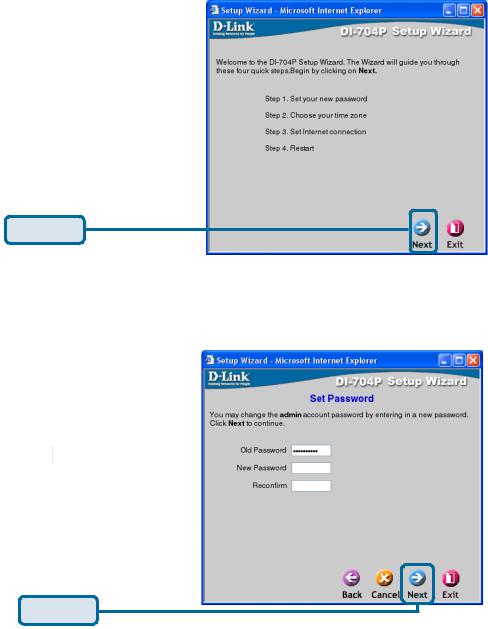
Using the Setup Wizard (continued)
You will see the following screens
Click Next
Set up your new password. You have the option to establish a password.
Click Next
13

Using the Setup Wizard (continued)
Set up your Time Zone. You have the option to the set standard time for your router. To change the default selection, select the drop down arrow and chose the correct time zone.
Click Next
Select your Internet Connection. You will be prompted to select the type of Internet connection for your router.
If you are unsure of which setting to select, please contact your Internet Service Provider.
Click Next
Select Others only if you use PPTP in Europe or
BigPond Cable in Australia.
14
Using the Setup Wizard (continued)
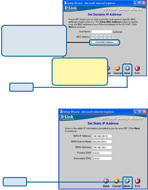
If you selected Dynamic IP Address, this screen will appear: (Used mainly for Cable Internet service.)
Click the “Clone MAC Address” button to automatically copy the MAC address of the network adapter in your computer. You can also manually type in the MAC address.
What is a MAC address? Each network adapter has a discrete Media Access Control (MAC) address. Note that some computers and peripherals may already include built-in network adapters.
Click Next
If your ISP requires a Static IP Address, and this option is selected, then this screen will appear:
Enter the IP Address information originally provided to you by your ISP. You will need to complete all the required fields.
Click Next
15
Using the Setup Wizard (continued)
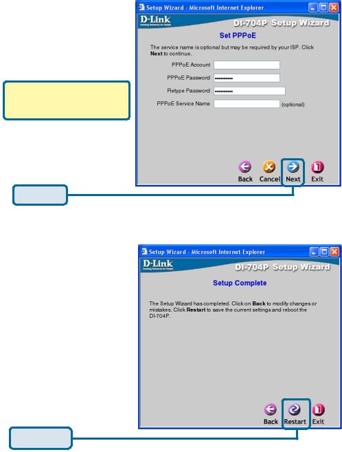
If your ISP uses PPPoE (Point-to-Point Protocol over Ethernet), and this option is selected, then this screen will appear: (Used mainly for DSL Internet service.)
Please be sure to remove any existing PPPoE client software installed on your computers.
Enter in the username and password provided to you by your ISP.
Click Next
Click Restart
16
Using the Configuration Menu
Whenever you want to configure your network or the DI-704P, you can access the Configuration Menu by opening the web-browser and typing in the IPAddress of the DI-
704P. The DI-704P default IP Address is shown below:
Open the web browser Type in the IP Address of the DI-704P
Home > Wizard
Note: if you have changed the default IP Address assigned to the DI-704P, make sure to enter the correct IP Address.
The factory default User name is
“admin” and the default Password is blank (empty). It is recommended that you change the admin password for security purposes. Please refer to Tools>Admin to change the admin password.
17
Using the Configuration Menu (continued)
Home > Wizard (continued)
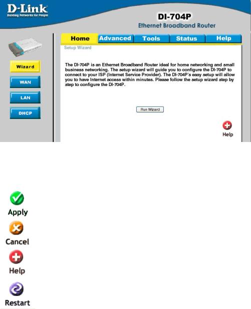
The Home>Wizard screen will appear. Please refer to the Quick Installation Guide for more information regarding the Setup Wizard.
Clicking Apply will save changes made to the page
Clicking Cancel will clear changes made to the page
Clicking Help will bring up helpful information regarding the page
Clicking Restart will restart the router. (Necessary for some changes.)
18
Using the Configuration Menu (continued)
Home > WAN (continued)
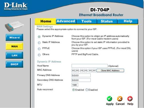
WAN is short for Wide Area Network. The WAN settings can be referred to as the Public settings. All IP information in the WAN settings are public IP addresses which are accessible on the Internet. The WAN settings consist of four options: Dynamic IP Address, Static IP
Address, PPPoE, and Others. Select the appropriate option and fill in the information needed to connect to your ISP.
Choose Dynamic IP Address to obtain IP address information automatically from your ISP. Select this option if your ISP does not give you any IP numbers to use. This option is commonly used for Cable modem services. Host Name: The Host Name field is optional but may be required by some ISPs. The host name is the device name of the Broadband Router.
19
Using the Configuration Menu (continued)
Home > WAN (continued)
MAC Address:
The default MAC address is set to the WAN’s physical interface MAC address on the Broadband Router. You can use the “Clone MAC Address” button to copy the MAC address of the Ethernet Card installed by your ISP and replace the WAN MAC address with this MAC address. It is not recommended that you change the default MAC address unless required by your ISP.
Primary/Secondary DNS Address:
Enter a DNS Address if you do not wish to use the one provided by your ISP.
MTU:
Only enter the MTU if it is required by your ISP. Otherwise, leave it at the default setting of 1500.
Auto-reconnect:
If enabled, the Broadband Router will automatically connect to your ISP after your system is restarted or if the connection is dropped.
20
Using the Configuration Menu (continued)
Home > WAN > Static IP Address
Choose Static IP Address if all WAN IP information is provided to you by your ISP. You will need to enter in the IP Address, subnet mask, gateway address, and DNS address(es) provided to you by your ISP. Each IP address entered in the fields must be in the appropriate IP form, which are four IP octets separated by a dot (x.x.x.x).
The Router will not accept the IP Address if it is not in this format.
IP Address:
Public IP address provided by your ISP.
Subnet Mask:
Subnet mask provided by your ISP.
ISP Gateway Address:
Public IP address of your ISP that you are connecting to.
Primary/Secondary DNS Address:
Enter a DNS Address if you do not wish to use the one provided by your ISP.
MTU:
Enter an MTU value only if required by your ISP. Otherwise, leave it at the default setting of 1500.
21
Using the Configuration Menu (continued)
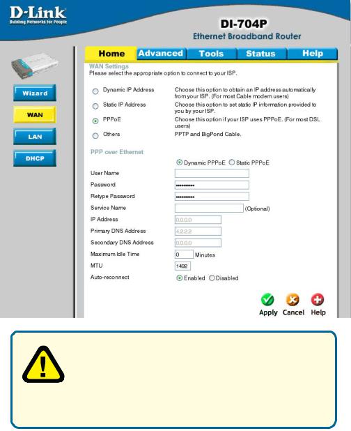
Home > WAN > PPPoE
Please be sure to remove any Client Software program on your computer before you start your configuration of the DI-704P Router. Choose PPPoE (Point to Point Protocol over Ethernet) if your ISP uses PPPoE connection. Your ISP will provide you with a username and password. This option is typically used for
DSL services. Select Dynamic PPPoE to obtain an IP address automatically for your PPPoE connection. Select Static PPPoE to use a static IP address for your PPPoE connection.
22
Using the Configuration Menu (continued)
Home > WAN > PPPoE (continued)
Dynamic PPPoE:
PPPoE connection where you will receive an IP address automatically from your ISP
Static PPPoE:
PPPoE connection where you have an assigned (static) IP address
User Name:
Your PPPoE username provided by your ISP
Password:
Your PPPoE password provided by your ISP
Retype Password:
Re-enter PPPoE password
Service Name:
Enter the service name provided by your ISP. (optional)
IP Address:
This option is only available for Static PPPoE. Enter in the static IP address for the PPPoE connection.
Primary DNS Address:
Primary DNS IP provided by your ISP
Secondary DNS Address:
Optional
Maximum Idle time:
The amount of time of inactivity before disconnecting your PPPoE session. Enter a Maximum Idle Time (in minutes) to define a maximum period of time for which the Internet connection is maintained during inactivity. If the connection is inactive for longer than the defined Maximum Idle Time, then the connection will be dropped. Either set this to zero or enable Auto-reconnect to disable this feature.
MTU:
MTU stands for Maximum Transmission Unit. For PPPoE connections, you may need to change the MTU settings in order to work correctly with your ISP.
Auto-reconnect:
If enabled, the Broadband Router will automatically connect to your ISP after your |
|
system is restarted or if the connection is dropped. |
23 |
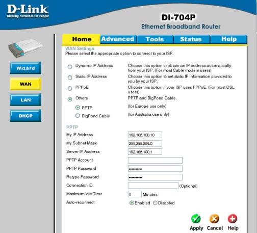
Using the Configuration Menu (continued)
Home > WAN > PPTP
Dynamic IP Address for PPTP is a WAN connection used in Europe.
My IP Address:
Enter in the IP address for the
My Subnet Mask:
Enter the subnet mask information.
Server IP:
Enter the Server IP address. By default, its set to 192.168.0.1
24
Using the Configuration Menu (continued)
Home > WAN > PPTP (continued)
PPTP Account:
Enter in the username for the PPTP account
PPTP Password:
Enter the password for the PPTP account. Retype in Password to confirm
Connection ID:
(Optional) enter the Connection ID if required
Maximum Idle Time:
The amount of time of inactivity before disconnecting your PPPoE session. Enter a Maximum Idle Time (in minutes) to define a maximum period of time for which the Internet connection is maintained during inactivity. If the connection is inactive for longer than the defined Maximum Idle Time, then the connection will be dropped. Either set this to zero or enable Auto-reconnect to disable this feature.
Auto-reconnect:
If enabled, the device will automatically connect to your ISP after your unit is restarted or when the connection is dropped.
25
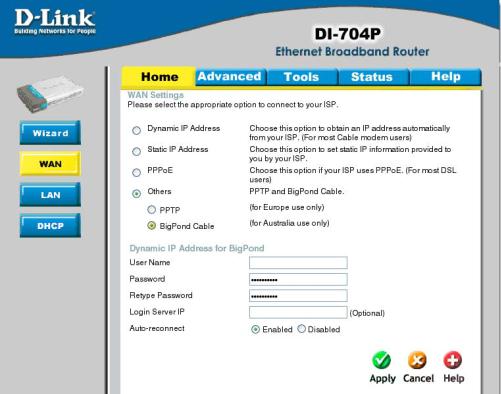
Using the Configuration Menu (continued)
Home > WAN > BigPond Cable
Dynamic IP Address for BigPond is a WAN connection used in Australia.
Account:
Enter in the username for the BigPond account
Password:
Enter the password for the BigPond account
Login Server:
(Optional) enter the Login Server name if required
Auto-reconnect:
If enabled, the device will automatically connect to your ISP after your unit is restarted or when the connection is dropped.
26

Using the Configuration Menu (continued)
Home > LAN
LAN is short for Local Area Network. This is considered your internal network. These are the IP settings of the LAN interface for the DI-704P. These settings may be referred to as Private settings. You may change the LAN IP address if needed. The LAN IP address is private to your internal network and cannot be seen on the Internet.
IP Address:
The IP address of the LAN interface. The default IP address is 192.168.0.1.
Subnet Mask:
The subnet mask of the LAN interface. The default subnet mask is 255.255.255.0.
Local Domain Name:
This field is optional. Enter in the your local domain name.
27
Using the Configuration Menu (continued)
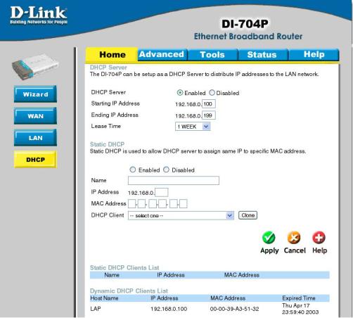
Home > DHCP
DHCP stands for Dynamic Host Control Protocol. The DI-704P has a built-in DHCP server. The DHCP Server will automatically assign an IP address to the computers on the LAN/private network. Be sure to set your computers to be DHCP clients by setting their TCP/IP settings to “Obtain an IP Address Automatically.” When you turn your computers on, they will automatically load the proper TCP/IP settings provided by the DI-704P. The DHCP Server will automatically allocate an unused IP address from the IP address pool to the requesting computer. You must specify the starting and ending address of the IP address pool.
28
Using the Configuration Menu (continued)
Home > DHCP
Static DHCP allows computers on the LAN to receive the same DHCP IP address everytime it boots up. You can bind a specific IP address to a specific computer
based on the computer’s MAC address
Starting IP address:
The starting IP address for the DHCP server’s IP assignment.
Ending IP address:
The ending IP address for the DHCP server’s IP assignment.
Lease Time:
The length of time for the IP lease.
29
Loading...