


Daikin GCU compact 315, GCU compact 324, GCU compact 515, GCU compact 524, GCU compact 315 Biv Installation manuals
...For certified companies
ROTEX
GCU compact
Installation and maintenance instructions
Gas Combi Unit compact
 0085 CO 0180
Types
GCU compact 315 GCU compact 324 GCU compact 515 GCU compact 524 GCU compact 533
GB
Edition
GCU compact 315 Biv GCU compact 324 Biv GCU compact 515 Biv GCU compact 524 Biv GCU compact 533 Biv

List of contents
1 Guarantee . . . . . . . . . . . . . 4
1.1 Warranty conditions . . . . . . . . . . . . . . . . . . . . . . 4
2 Safety . . . . . . . . . . . . . . . . . . . . . . . . . . . . . . 5
2.1 Observing instructions . . . . . . . . . . . . . . . . . . . . 5 2.2 Warning signs and explanation of symbols . . . . 5 2.3 Avoid danger . . . . . . . . . . . . . . . . . . . . . . . . . . . 5 2.4 Proper use . . . . . . . . . . . . . . . . . . . . . . . . . . . . . 5 2.5 Instructions for operating safety. . . . . . . . . . . . . 6
2.5.1 Before working on the heating system . . . . . . . . . .6 2.5.2 Electrical installation . . . . . . . . . . . . . . . . . . . . . . . .6 2.5.3 Installation room . . . . . . . . . . . . . . . . . . . . . . . . . . .6 2.5.4 Requirements for the heating water . . . . . . . . . . . .6 2.5.5 Heating system and sanitary connection . . . . . . . .6 2.5.6 Fuel . . . . . . . . . . . . . . . . . . . . . . . . . . . . . . . . . . . . .6 2.5.7 Operation . . . . . . . . . . . . . . . . . . . . . . . . . . . . . . . .6 2.5.8 Instructing the user/owner. . . . . . . . . . . . . . . . . . . .6
3 Product description. . . . . . . . . . . . . . . . . . . 7
3.1 Design and components . . . . . . . . . . . . . . . . . . 7
3.1.1 GCU compact 315 / 324 . . . . . . . . . . . . . . . . . . . . .7 3.1.2 GCU compact 515 / 524 / 533. . . . . . . . . . . . . . . . .8
3.2 Brief description . . . . . . . . . . . . . . . . . . . . . . . . . 9
4 Set-up and installation . . . . . . . . . . . . . . . 11
4.1 Dimensions and connection dimensions . . . . . 11
4.1.1Connection dimensions for the heating and
hot water connections . . . . . . . . . . . . . . . . . . . . . .12
4.2 Installation versions . . . . . . . . . . . . . . . . . . . . . 14
4.2.1 Operation independent of ambient air. . . . . . . . . .15 4.2.2 Operation partially independent of ambient air . . .16 4.2.3 Ambient air dependent operation . . . . . . . . . . . . .16
4.3 Transport and delivery . . . . . . . . . . . . . . . . . . . 16 4.4 Installing the Gas Combi Unit compact . . . . . . 16
4.4.1 Selecting the installation site . . . . . . . . . . . . . . . .16 4.4.2 Setting up the unit . . . . . . . . . . . . . . . . . . . . . . . . .17 4.4.3 Remove the sound insulation hood. . . . . . . . . . . .18
4.5 Air/flue system (LAS) . . . . . . . . . . . . . . . . . . . . 18
4.5.1 General instructions for flue system . . . . . . . . . . .18 4.5.2 Connecting a flue gas line. . . . . . . . . . . . . . . . . . .19 4.5.3 Flue gas system kits . . . . . . . . . . . . . . . . . . . . . . .20
4.6 Water connection . . . . . . . . . . . . . . . . . . . . . . . 21
4.6.1 Connecting the safety group (SBG) . . . . . . . . . . .21 4.6.2 Connecting hydraulic lines . . . . . . . . . . . . . . . . . .22 4.6.3 Connect the condensate drain . . . . . . . . . . . . . . .23
4.7 Connection Control and Electrics. . . . . . . . . . . 23
4.7.1 Instructions concerning electrical connection . . . .23 4.7.2 Establishing the electrical connection . . . . . . . . . .23
4.7.3Integrated heating circulation pump and
3-way-valve . . . . . . . . . . . . . . . . . . . . . . . . . . . . . .25
4.8 Temperature sensor. . . . . . . . . . . . . . . . . . . . . 25
4.8.1Connecting the exterior temperature sensor
RoCon OT1 . . . . . . . . . . . . . . . . . . . . . . . . . . . . . .25
4.9Connect the gas line, check the burner
setting for gas type. . . . . . . . . . . . . . . . . . . . . . 26
4.9.1 Important instructions for gas connection . . . . . . .26 4.9.2 Connecting the gas line. . . . . . . . . . . . . . . . . . . . .26 4.9.3 Installing/removing the burner trim . . . . . . . . . . . .26 4.9.4 Checking the gas pre-installation . . . . . . . . . . . . .27
4.10 Optional connections . . . . . . . . . . . . . . . . . . . . 28
4.10.1 Mixer module RoCon M1 . . . . . . . . . . . . . . . . . . .28 4.10.2 Room control RoCon U1 . . . . . . . . . . . . . . . . . . . .28
4.10.3 Internet Gateway RoCon G1 . . . . . . . . . . . . . . . . 28
4.11 Filling the system . . . . . . . . . . . . . . . . . . . . . . 28
4.11.1 Check the water quality and adjust the pressure gauge . . . . . . . . . . . . . . . . . . . . . . . . . . . . . . . . . 28
4.11.2 Filling the hot water heat exchanger . . . . . . . . . . 28 4.11.3 Filling the storage tank . . . . . . . . . . . . . . . . . . . . 28 4.11.4 Filling the heating system and the storage tank
charging circuit . . . . . . . . . . . . . . . . . . . . . . . . . . 30
5 Start-up. . . . . . . . . . . . . . . . . . . . . . . . . . . . .31
5.1 Initial start-up. . . . . . . . . . . . . . . . . . . . . . . . . . 31
5.1.1 Requirements . . . . . . . . . . . . . . . . . . . . . . . . . . . 31 5.1.2 Checks before start-up . . . . . . . . . . . . . . . . . . . . 31 5.1.3 Start-up . . . . . . . . . . . . . . . . . . . . . . . . . . . . . . . . 31 5.1.4 After start-up . . . . . . . . . . . . . . . . . . . . . . . . . . . . 32
5.2 Checklists for start-up . . . . . . . . . . . . . . . . . . . 33
6 Control unit . . . . . . . . . . . . . . . . . . . . . . . . .34
6.1Operating elements on the boiler control
|
panel . . . . . . . . . . . . . . . . . . . . . . . . . . . . . . . . |
34 |
6.2 |
Replacing the operating section RoCon B1 . . |
35 |
6.3 |
Changing the sensors . . . . . . . . . . . . . . . . . . . |
35 |
6.3.1Changing the flow temperature sensor / return
temperature sensor and pressure sensor . . . . . . 36
6.3.2Changing the internal mixer sensor for heating
support (only GCU compact 5xx) . . . . . . . . . . . . 36
6.3.3Changing the storage tank temperature sensor . 37
7 Gas burner . . . . . . . . . . . . . . . . . . . . . . . . . .38
7.1 Structure and brief description . . . . . . . . . . . . 38 7.2 Safety function . . . . . . . . . . . . . . . . . . . . . . . . 39 7.3 Burner setting . . . . . . . . . . . . . . . . . . . . . . . . . 39
7.3.1 |
Setting values . . . . . . . . . . . . . . . . . . . . . . . . . . . |
40 |
7.3.2 Establishing access to the burner . . . . . . . . . . . . |
40 |
|
7.3.3 |
Checking and setting the burner . . . . . . . . . . . . . |
40 |
7.3.4Starting problems - calibrate the firing unit, starting output burner blower and setting the
gas volume . . . . . . . . . . . . . . . . . . . . . . . . . . . . . 41 7.3.5 Setting ignition and Ionisation electrodes . . . . . . 43
7.4 Dismantling the burner . . . . . . . . . . . . . . . . . . 43
8 Hydraulic connection . . . . . . . . . . . . . . . . .45
8.1 Hydraulic system connection . . . . . . . . . . . . . 45
9 Service and maintenance . . . . . . . . . . . . . .47
9.1General overview of service and maintenance 47
9.2 Service and maintenance tasks . . . . . . . . . . . 47
9.2.1 Checking the connections and pipes. . . . . . . . . . 47 9.2.2 Checking and cleaning the condensate drain. . . 47 9.2.3 Checking and cleaning the burner. . . . . . . . . . . . 48
10 Faults and malfunctions . . . . . . . . . . . . . . .49
10.1 Troubleshooting . . . . . . . . . . . . . . . . . . . . . . . 49 10.2 Overview of possible malfunctions . . . . . . . . . 49 10.3 Fault codes . . . . . . . . . . . . . . . . . . . . . . . . . . . 51 10.4 Rectifying burner faults and STB faults. . . . . . 53 10.5 Emergency operation . . . . . . . . . . . . . . . . . . . 54
10.5.1 Parallel operation . . . . . . . . . . . . . . . . . . . . . . . . 54
11 Taking out of service. . . . . . . . . . . . . . . . . .55
11.1 Temporary shutdown . . . . . . . . . . . . . . . . . . . 55 11.2 Final shutdown and disposal. . . . . . . . . . . . . . 55
2 |
ROTEX GCU compact - |

List of contents
12 Technical data . . . . . . . . . . . . . . . . . . . . . . . 56
12.1 Basic data . . . . . . . . . . . . . . . . . . . . . . . . . . . . .56
12.1.1 GCU compact 3xx . . . . . . . . . . . . . . . . . . . . . . . . 56 12.1.2 GCU compact 5xx . . . . . . . . . . . . . . . . . . . . . . . . 57 12.1.3 Integrated gas burner . . . . . . . . . . . . . . . . . . . . . 58 12.1.4 Integrated heating circulation pump, 3-way valve 58
12.2 Gas type, connection pressures . . . . . . . . . . . .59 12.3 Tightening torque . . . . . . . . . . . . . . . . . . . . . . .60 12.4 Flow rate and residual feed height . . . . . . . . . .60 12.5 Temperature sensor . . . . . . . . . . . . . . . . . . . . .60 12.6 Electrical connection diagram . . . . . . . . . . . . . .61
13 Notes . . . . . . . . . . . . . . . . . . . . . . . . . . . . . . 62 14 List of keywords . . . . . . . . . . . . . . . . . . . . . 63
15 For the chimney sweep . . . . . . . . . . . . . . . 64
15.1 Data for designing the flue gas pipe . . . . . . . . .64 15.2 Emissions measurement. . . . . . . . . . . . . . . . . .64
ROTEX GCU compact - |
3 |

1 Guarantee
1 Guarantee
1.1 Warranty conditions
The legal guarantee conditions fundamentally apply. Our warranty conditions beyond that can be found online on your sales representative's webpage.
4 |
ROTEX GCU compact - |
2 Safety
2 Safety
2.1 Observing instructions
This instruction is the >> Original Version << in your language.
Please read this manual carefully and thoroughly before proceeding with the installation or modification of the heating system.
These instructions are intended for authorised and trained heating and sanitation experts who have experience in the proper installation and maintenance of heating systems and hot water storage tanks by virtue of their technical training and knowledge.
This manual provides all the necessary information for installation, start-up and maintenance, as well as basic information on operation and settings. Please go through the attached documents for a detailed description of operation and control.
All heating parameters needed for smooth operation are already factory-set. Please refer to other relevant documents for information on setting the control.
Relevant documents
–ROTEX GCU compact:
–For the operator
–Operating manual for the operator.
–ROTEX RoCon BF: Operating instructions.
–When connecting additional ROTEX components; the associated installation and operating instructions.
The guides are included in the scope of supply for the individual units.
2.2 Warning signs and explanation of symbols
Meaning of the warnings
Warnings in this manual are classified according into their severity and probability of occurrence.
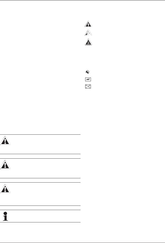
DANGER!
Draws attention to imminent danger.
Disregarding this warning can lead to serious injury or death.
WARNING!
Indicates a potentially dangerous situation.
Disregarding this warning can result in serious injury or death.
CAUTION!
Indicates a situation which may cause possible damage.
Disregarding this warning can lead to damage to property and the environment.
This symbol identifies user tips and particularly useful information, but not warnings or hazards.
Special warning signs
Some types of danger are represented by special symbols:
Electric power
Danger of explosion
Risk of burning or scalding
 Risk of poisoning
Validity
Some information in this manual has limited validity. The validity is highlighted by a symbol.
Pay attention to the stipulated tightening torque (See chapter 12.3 "Tightening torque")
Only applies for units with unpressurised solar system connection (Drain Back).
Only applies for units with a bivalent solar system connection (BIV).
Order number
Information about order numbers are identified with the shopping basket icon  .
.
Handling instructions
ƔInstructions on actions are shown as a list. Actions of which the sequential order must be maintained are numbered. Î Results of actions are identified with an arrow.
2.3 Avoid danger
ROTEX Gas Combi Unit compact conforms to the state-of-the-art and meets all recognised technical requirements. However, improper use may result in serious physical injuries or death, as well as property damage. Install and operate only ROTEX Gas Combi Unit compact to avoid danger:
–as stipulated and in perfect condition,
–with an awareness of the safety and hazards involved.
This assumes knowledge and use of the contents of this manual, the relevant accident prevention regulations and the recognised safety-related and occupational medical rules.
2.4 Proper use
The ROTEX GCU compact may only be used for the heating of hot water heating systems. It may only be erected, connected and operated only according to the indications in this manual.
The ROTEX GCU compact must only be operated with the integrated circulation pump and only in connection with a control system that has been approved by ROTEX.
Any other use outside the intended use is considered as improper and leads to a loss of warranty. The operator alone shall bear responsibility for any resulting damage.
Proper use also includes observing the relevant maintenance and servicing conditions. Spare parts must at least satisfy the technical requirements defined by the manufacturer. This is the case, for example, with original spare parts.
ROTEX GCU compact - |
5 |

2 Safety
2.5 Instructions for operating safety
2.5.1 Before working on the heating system
ƔWork on the heating system (such as installation, connection and initial start-up) may only be carried out by authorised, trained heating technicians.
ƔSwitch off the main switch and secure it against unintended switching on when carrying out any work on the heating system.
ƔSeals must not be damaged or removed.
ƔMake sure that the safety valves comply with the requirements of EN 12828 when connecting on the heating side, and with the requirements of EN 12897 when connecting on the domestic water side.
2.5.2 Electrical installation
ƔElectrical installations must only be conducted by electrical engineers and in compliance with valid electrical guidelines as well as the specifications of the energy supply company.
ƔBefore completing the mains connection, compare the mains voltage, indicated on the type plate (230 V, 50 Hz) with the supply voltage.
ƔBefore beginning work on live parts, disconnect them from the power supply (switch off main switch, remove fuse) and secure against unintentional restart.
ƔEquipment covers and service panels must be replaced as soon as the work is completed.
2.5.3 Installation room
ƔOperate ROTEX GCU compact only if sufficient combustion air supply is ensured. If you operate the ROTEX GCU compact in a room-air independent manner with a concentric air/flue gas system (LAS) dimensioned as per ROTEX standard, this is fulfilled automatically and there are no other conditions for the equipment erection room. With installation in residential rooms, this method of operation applies exclusively.
ƔMake sure that, with installation in a room-air dependent or
limited room-air independent manner, an inlet air opening to the outside of at least 150 cm2 is provided.
ƔDo not operate the ROTEX GCU compact by the ambient air dependent method in rooms with aggressive vapours (e.g. hair spray, perchloroethylene, carbon tetrachloride), strong dust formation (e.g. workshop) or high humidity (e.g. laundry).
ƔStrictly keep the minimum distances to walls and other objects (see chapter 4.1).
2.5.4 Requirements for the heating water
Avoid damage caused by deposits and corrosion: Observe the relevant regulations of technology to prevent creation of corrosion products and deposits.
Measures for desalination, softening or hardness stabilization are necessary, if the filling and top-up water have a high total hardness (>3 mmol/l - sum of the calcium and magnesium concentrations, calculated as calcium carbonate.
Using filling water and top-up water which does not meet the stated quality requirements can cause a considerably reduced service life of the equipment. The responsibility for this is entirely that of the operator.
2.5.5 Heating system and sanitary connection
ƔCreate a heating system according to the safety requirements of EN 12828.
ƔWith sanitary connection, you must observe;
–EN 1717 - Protection of potable water from contamination in domestic water installations and general requirements concerning safety equipment for the prevention of domestic water contamination by back-flow
–EN 806 - Technical regulations for domestic water installations (TRWI)
–and, in addition, the country-specific legal regulations.
During operation of the ROTEX GCU compact with hot water storage, the storage tank temperature may exceed 60°C, particularly when solar power is used.
ƔTherefore, incorporate scald protection during the installation
of the system (domestic hot water mixing construcion, e.g. VTA32,  15 60 16).
2.5.6 Fuel
The ROTEX GCU compact is factory set to the gas type indicated on the burner sticker and on the settings type plate and adjusted to the gas pressure indicated on the burner sticker.
ƔOperate the unit only with the gas type and gas pressure indicated on these stickers.
ƔInstallation and adaptation of the gas system must only be conducted by personnel qualified for this work and in compliance with valid gas installation related guidelines as well as the applicable regulations of the gas supply company.
2.5.7 Operation
ƔOperate ROTEX GCU compact only with closed silencer hoods.
ƔOnly operate the ROTEX GCU compact if all the requirements as per the checklist in chapter 5.2 are fulfilled.
2.5.8 Instructing the user/owner
ƔBefore you hand over the heating system, explain to the owner how he/she can operate and check the heating system.
ƔHand over the technical documentation (at least the operating instruction manual and operating handbook) to the user and advise him that these documents must be made available at all times and be stored in the immediate vicinity of the unit.
ƔMake a record of the handover by filling out and signing the installation and instruction forms jointly with the user/owner.
6 |
ROTEX GCU compact - |
3 Product description
3 Product description
3.1 Design and components
3.1.1 GCU compact 315 / 324 |
|
|
|
|
|
|
|
|
|
|
|
|
|
|
|
|
|
|
|
|
|
|
|
|
|
|
|
|
|
89 '+: |
|
|
|
|
|
|
|
|
|
|
|
|
|
|
|
|
|
|
|
|
|
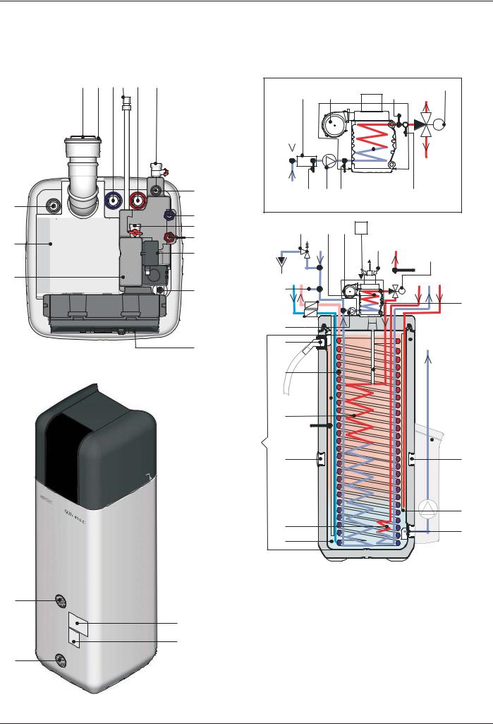
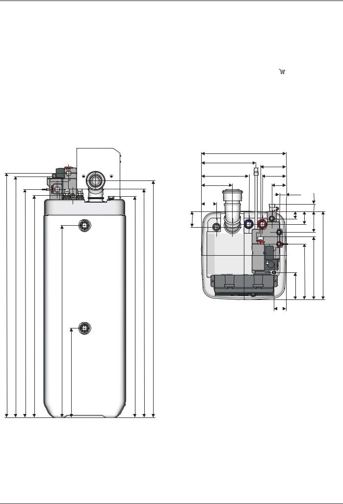
Fig. 3-1 Structure and components GCU compact 315/324 - plan view (for legend designations, see tab. 3-1)


; |
)/6 |
|
|
|
W9 |
89 '+: |
|
|
|
||||
|
|
|
|
|
|
|
|
|
|
|
|
|
$ |
|
|
|
|
|
|
0 |
|
|
|
|
|
|
% |
|
|
|
|
|
|
|
|
|
|
|
|
|
|
|
W5 |
|
W5 |
|
|
'6 |
|
|
|
|
; |
|
|
|
|
|
|
|
|
|
|
|
|
|
|
|
89 '+: |
|
|
|
|
|
|
W9 |
|
|
|
|
|
$ |
|
|
|
|
|
0 |
||
|
|
|
|
% |
||
|
|
|
|
|
$ |
|
|
|
|
|
|
|
|
|
|
|
|
|
|
|
|
|
|
|
|
|
% |
|
|
|
|
|
|
|
|
|
|
|
|
|
|
|
|
|
|
|
|
|
|
|
|
|
|
|
|
|
|
|
|
|
|
|
|
W'+: |
|
|
|
|
536 |
' |
|
|
|
|
|
|
|
|
|
|
|
|
|
|
|
|
|
|
|
|
|
|
|
|
|
|
|
& |
|
|
|
|
|
|
|
|
|
|
|
|
Fig. 3-3 Structure and components GCU compact 315 / 324 -
Schematic view (for legend designations, see tab. 3-1)
Fig. 3-2 Structure and components GCU compact 315 / 324 - front view (for legend designations, see tab. 3-1)
ROTEX GCU compact - |
7 |
3 Product description
3.1.2 GCU compact 515 / 524 / 533
|
; |
)/6 |
|
|
|
W9 |
89 '+: |
|
|
|
|
|
|
|
|
|
|
|
|
|
|
|
|
|
|
|
|
|
|
|
|
|
|
|
|
|
|
|
|
|
|
|
|
|
|
|
|
|
|
|
|
|
|
|
|
W5 |
|
W5 |
|
|
'6 |
|
|
|
|
|
|
|
89% W9 |
|
|
|
|
|
|
|
|
|
|
|
|
|
|
|
|
; |
|
|
|
|
|
|
|
|
|
|
|
|
|
|
|
|
|
|
|
|
|
|
|
|
|
|
|
|
||
|
|
|
|
|
|
|
|
|
|
|
|
|
|
|
|
|
|
|
|
|
|
|
|
|
|
89 '+: |
|
|
|
|
|
|
|
||
|
|
|
|
|
|
|
|
|
|
|
|
|
|
|
|
|
$ |
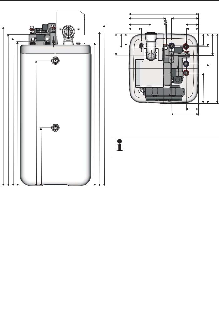
Fig. 3-4 Structure and components GCU compact 515 / 524 / 533 - |
|
|
|
|
|
|
|
|
|
|
|
|
|
|
|
|
|
plan view (for legend designations, see tab. 3-1) |
|
|
|
|
|
|
|
% |
|
|
|
|
|
|
|
|
|
|
|
|
|
|
|
|
|
|
|
|
|
|
|
|
|
|
|
' |
|
|
|
|
|
|
|
|
|
|
|
|
|
|
|
|
|
|
|
|
|
|
|
|
|
|
|
|
|
|
|
|
|
|
536 |
|
|
|
|
|
|
|
|
|
|
|
|
|
|
|
|
|
|
|
|
|
|
|
|
|
||
|
|
|
|
|
|
|
|
|
( |
|
|
|
|
|
|
|
|
|
|
|
|
|
|
|
||
|
& |
|
|
|
|
|
|
|
|
|
|
|
|
|
|
|
|
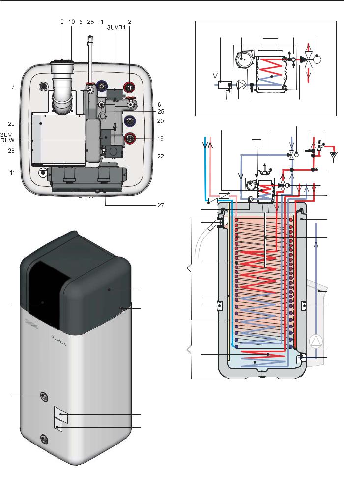
Fig. 3-6 Structure and components GCU compact 515 / 524 / 533 -
Schematic view (for legend designations, see tab. 3-1)
Fig. 3-5 Structure and components GCU compact 515 / 524 / 533 - front view (for legend designations, see tab. 3-1)
8 |
ROTEX GCU compact - |
3 Product description
1Cold water connection (1" AG)  2)
2)
2Hot water (1" AG)  2)
2)
3Storage charge - flow (1" AG) 
4Storage charge - return flow (1" AG) 
5Heaterflow (1" AG)*  2)
2)
6Heaterreturn flow (1" AG)* 
7


 Solar - flow (1" IG)
8Draining connection or 


 solar return flow
9Exhaust
10Supply air
11Sensor immersion sleeve for storage temperature sensor tDHW
12Upper filling connection and condensate overflow connection 
13Condensation drain pipe
14Condensate pipe
15Heating heat exchanger (boiler body)
16Heat exchanger (stainless steel) for drinking water heating
17Heat exchanger (stainless steel) for storage tank charging or heating support
18Heat exchanger (stainless steel) for bivalent storage charge 1)
19 BIV storage charge - flow 1)2) (1" AG)
20


 BIV storage charge - return flow 1) (1" AG)
21


 Solar inflow layering pipe
22Heating circulation pump
23Burner blower
24 |
Safety overpressure valve (heating circuit) |
|
A |
Gas boiler |
|
|||
|
3) |
|
B |
Storage tank (polypropylene double walled |
||||
25 |
Connection for SBG GCU compact 3) |
|
|
|
jacket with PUR hard foam heat insulation) |
|||
26 |
Gas connection (G ½" IG) with connected |
|
C |
Unpressurised storage tank water |
||||
|
gas hose |
|
D |
Hot water zone |
|
|||
27 |
Boiler control panel with RoCon BF control |
|
DS |
Pressure sensor |
|
|||
28 |
Heat insulation |
|
E |
Solar zone |
|
|||
29 |
Burner trim |
|
FLS1 |
|
|
|
|
|
30 |
Silencer hood |
|
|
|
Flow sensor with return temperature sen- |
|||
31 |
Insertion mount, sound insulation hood |
|
|
|
sor tR1 (boiler |
|
||
32 |
Type plate |
|
circuit) 536 |
|
||||
33 |
Setting type plate |
|
|
|
Optional: ROTEX Solaris R3 regulation |
|||
34 |
Threaded insert for carrying loop |
|
|
|
and pump unit |
|
|
|
35 |
Cover screen boiler control panel |
|
AG |
Male thread |
|
|||
|
|
|
|
|||||
|
|
|
IG |
Female thread |
|
|||
3UV DHW |
|
ÜM |
Union nut |
|
||||
|
3-way change valve (distribution valve |
|
|
|
Safety devices |
|
||
|
KRW ZDWHU KHDWLQJ KHDWLQJ VXSSRUW) |
|
|
|
|
|||
3UV% |
|
|
|
Observe tightening torque! |
|
|||
|
|
|
|
|
|
|
||
|
3-way change valve (mixer valve) |
* |
|
Ball cock (1" IG) is supplied with the equip- |
||||
tDHW Storage temperature sensor |
|
|||||||
1) |
|
ment |
|
|||||
tR |
Return temperature sensor 1 in FLS1 |
|
Only valid for types with BIV configuration |
|||||
2) |
|
|||||||
|
(boiler circuit) |
|
Recommended accessories: |
|
||||
tR |
Return temperature sensor 2 (boiler |
3) |
|
Non-return valves (2 pcs.), |
16 50 70 |
|||
|
circuit) |
|
Recommended accessories: |
|
||||
tV1 |
Flow temperature sensor (boiler circuit) |
|
|
|
Safety group SBG GCU compact, |
|||
tV2 |
Internal mixer sensor (boiler circuit) |
|
|
|
15 70 46 |
|
|
|
|
|
|
|
|
|
|
||
|
|
|
|
|
|
|
|
|
Tab. 3-1 Legend from fig. 3-1 to fig. 3-6
3.2 Brief description
Die ROTEX Gas Combi Unit compact (GCU compact) is a fully preassembled gas condenser unit., which is built into a water storage tank. The excellent heat insulation properties of the plastic storage tank ensure that heat losses are kept to a minimum. The aluminium boiler body is inserted in a metal housing in the cover of the storage tank. The complete flue gas unit is surrounded by fresh air.
Operating mode
The ROTEX GCU compact is designed such that it can be operated independently of the ambient air (concentric flue gas/air inlet piping). The burner suctions the combustion air directly in through an installation shaft or a double-walled flue gas pipe. This procedure is recommended by ROTEX and has many advantages:
–The heating room does not need any ventilation opening into the open air and therefore does not cool down.
–Lower energy consumption.
–Additional energy recovery in the flue gas pipe through preheating the combustion air.
–Contamination from the environment of the burner are not suctioned in. The heating room can thus be used as a work-space, laundry room etc. at the same time.
–Possible to set up in loft areas or attic.
The condensate which arises is collected in the flue gas collector and transported into the storage tank via a plastic pipe where it is neutralised.
The pressureless storage water serves as heat storage medium. Useful heat is supplied and led out by completely submerged, helically intertwined stainless steel corrugated tubes (1.4404).
The hot water zone in the storage tank works as a combination of heat storage and geyser (see fig. 3-3 and fig. 3-6).
The cold water which flows out when the hot water is removed is first routed to the storage tank at the very bottom of the heat exchanger, where it cools the lower area of the storage tank down as much as possible. The readiness zone is heated by a heat exchanger for charging storage tank (SL-WT) which is heated using the gas burner, heated from top to bottom where the water also flows.
On its way to the top, the domestic water continuously absorbs the heat of the storage tank water. The flow direction, operating on the principle of counter-flow, and the coil-shaped heat exchanger create a pronounced temperature layering in the hot water storage tank. As high temperatures can be maintained for a very long time in the upper section of the storage tank, a high hot water output is achieved even if water is drawn off over a long period of time.
–On the GCU compact 515/515-BIV, 524/524-BIV models, the SL-WT ends approx. 40 cm above the floor of the container. Only the hot water zone about it is heated by the boiler. The tank volume below it is heated only on using the solar energy.
–On the GCU compact 315/315-BIV, 324/324-BIV, 533/533BIV models, the SL-WT is pulled down all the way to the container floor. The entire storage volume is heated by the boiler (greater hot water output readiness).
Optimum water hygiene
Low flow or unheated zones on the domestic water side are completely excluded with the ROTEX GCU compact. It is impossible for sludge, rust or other sediments to be deposited, as can be the case with other large volume tanks. The water which is fed into the system first is also discharged first (first in, first out principle).
ROTEX GCU compact - |
9 |

3 Product description
Low scaling
On the storage tank side only one deposition of scale is possible. All the stainless steel heat exchanger pipes in the storage tank water largely remain without fixed coverings. This means that no scale can build up which would continuously reduce the efficiency of heat transfer in the course of operation.
The thermal and pressure expansion and high flow rates in the domestic water heat exchanger release any possible scale deposits, which are then flushed away.
Solar utilisation
The hot water storage tank of ROTEX GCU compact can also be used by solar energy. Depending on the available heat from the sun, the entire hot water storage tank can be heated up. The stored heat is used for hot water generation and also for heating support on types GCU compact 5xx. The ISM ("Intelligent Storage Manager") controls the integrated 3-way valves in such a way that the solar heat yield is optimally divided up and used for the hot water generation and heating support. The high total storage capacity allows for bridging of the periods without any solar yield.
If a ROTEX pressurised solar system or an external heating boiler is used as an external heat generator, this means that only one of the - listed in section 3.1 - GCU compact with BIV configuration is permitted as the primary hot water storage unit.
On the models GCU compact BIV, the complete storage tank is designed as a hot water zone. It is possible to make thermal use of solar energy for hot water preparation. In connection with a ROTEX Solaris plant connected in series (preheating stage), the solar proportion is optimised.
Safety management
The entire safety management of the ROTEX GCU compact is entrusted to electronic control. This effects a safety switch-off in the event of water shortage, gas shortage or undefined operating states. A corresponding fault signal provides an engineer with all the necessary information for troubleshooting.
Electronic control
An electronic digital controller combined with the "intelligent" automatic firing unit of the burner controls all heating and hot water functions automatically for the direct heating circuit and a storage tank charging circuit.
Optionally, connected mixer modules RoCon M1 ( 15 70 68) can be used to connect and regulate one or more mixed circuits.
All settings, displays and functions are made via the integrated RoCon BF control. The display and operating elements offer convenient operating possibilities.
As an option, for increased convenience, a digital room controller (RoCon U1,  15 70 34) is available as an option. This can be used as a remote control and a room thermostat.
Using the optional gateway (RoCon G1,  15 70 56), the controller can be connected to the internet. This means that the ROTEX GCU compact can be controlled remotely via mobile phone (using an App).
Condensing technology
The calorific value engineering makes optimum use of the energy contained in the heating gas. The flue gas is cooled down in the boiler and in the flue system - when operated independently of ambient air - such that the temperature is below the dew point. A part of the water vapour generated on combustion of the gas thus condenses. The condensation heat is fed to the heating, unlike low temperature boilers, which makes efficiencies of over 100 % possible (in relation to the lower heating value).
10 |
ROTEX GCU compact - |
4 Set-up and installation
4 Set-up and installation
WARNING!
Incorrectly erected and installed gas devices may not operate properly and are dangerous for the health and safety of individuals.
ƔThe ROTEX GCU compact must be installed only by heating engineers authorised and trained by gas or energy supply companies.
4.1Dimensions and connection dimensions
Incorrect set-up and installation would render the manufacturer's guarantee for the unit void. If you have questions, please contact our Technical Customer Service.
U |
<![if ! IE]> <![endif]>V |
U |
|
<![if ! IE]> <![endif]>' |
|
| <![if ! IE]> <![endif]>5 |
A |
B |
|
| <![if ! IE]> <![endif]>K |
|||
|
|
||
|
<![if ! IE]> <![endif]>K |
<![if ! IE]> <![endif]>K K |
|
|
|
|
|
|
|
|
|
|
|
|
V |
|
|
|
W |
|
|
|
|
Z |
||
|
|
|
|
|
|
|
|
|
|
|
|
<![endif]>V
C
A |
Side view |
C Top view |
B |
Front view |
|
Fig. 4-1 Installation dimensions for flue gas pipe at the rear (for values see tab. 4-1)
U |
<![if ! IE]> <![endif]>V |
|
<![if ! IE]> <![endif]>' |
| <![if ! IE]> <![endif]>5 |
|
|
|
|
A |
|
|
|
|
|
|
|
|
|
|||
| <![if ! IE]> <![endif]>K |
|
|
|
|
|
|
||
|
|
|
|
|
|
|
||
| <![if ! IE]> <![endif]>K |
|
|
|
|
|
<![if ! IE]> <![endif]>K |
<![if ! IE]> <![endif]>K |
|
|
|
|
|
|
|
|
|
|
|
|
|
|
|
|
|
|
|
|
|
|
|
|
|
|
|
|
 V W
V W
|
U |
|
<![if ! IE]> <![endif]>V |
|
C |
B |
V |
<![endif]> V
V
C
Z |
V |
A |
Side view |
C Top view |
B |
Front view |
|
Fig. 4-2 Installation dimensions for flue gas pipe at the side (for values see tab. 4-1)
ROTEX GCU compact - |
11 |
4 Set-up and installation
Dim. |
GCU compact 3xx |
|
GCU compact 5xx |
h1 |
|
1380 |
|
|
|
|
|
h2 |
1920 |
|
1950 |
|
|
|
|
h3 |
|
1560 |
|
|
|
|
|
hR |
2070 |
|
2100 |
r1 |
110 |
|
250 |
|
|
|
|
r2 |
380 |
|
540 |
|
|
|
|
s1 |
|
345 |
|
|
|
|
|
s2 |
350, 4701) |
|
200, 3201) |
s3 |
535, 3651), 2852) |
|
500, 3301), 2502) |
s4 |
370, 2001), |
|
210, 401), |
Dim. |
GCU compact 3xx |
|
GCU compact 5xx |
s5 |
750, 630 |
1), 5002) |
|
s6 |
750, 6301), 5002) |
|
750, 6301) |
sD |
|
150 |
|
t |
615 |
|
790 |
|
|
|
|
w |
595 |
|
790 |
|
|
|
|
1)When installing the test adapter to the rear.
2) When using a shorter exhaust pipe D8 L25 ( |
15 50 79.0102) instead of |
the exhaust pipe D8 L50 contained in SET. |
|
Tab. 4-1 Connectionand set-up dimensions GCU compact in mm (in relation to fig. 4-1, fig. 4-2, fig. 4-10, fig. 4-13, fig. 4-14)
4.1.1 Connection dimensions for the heating and hot water connections |
|
|
|
|||
GCU compact 3xx |
|
|
|
|
|
|
|
|
|
|
|
|
|
|
|
|
|
|
|
|
|
|
|
|
|
|
|
|
|
|
|
|
|
|
|
|
|
|
|
|
|
|
|
|
|
|
<![if ! IE]> <![endif]> |
|
|
|
|
|
|
|
|
|
|
|
|
|
|
|
|
|
|
B |
<![if ! IE]> <![endif]> |
|
|
|
|
|
<![if ! IE]> <![endif]> |
<![if ! IE]> <![endif]> |
<![if ! IE]> <![endif]> |
|
|
|
|
Gc 3xx |
|
|
<![if ! IE]> <![endif]> |
|
|
|
|
|
|
|
|
|
|
|
|
<![if ! IE]> <![endif]> |
<![if ! IE]> <![endif]> |
| <![if ! IE]> <![endif]> |
<![if ! IE]> <![endif]> |
<![if ! IE]> <![endif]> |
A |
<![if ! IE]> <![endif]> |
|
|
|
|
|
|
|
|
|
| <![if ! IE]> <![endif]> |
B |
Rear side |
Gc GCU compact |
|
A |
Front side |
|
|
Fig. 4-4 Connection dimensions GCU compact 3xx (plan view) |
||
Fig. 4-3 Connection dimensions GCU compact 3xx (view from behind)
12 |
ROTEX GCU compact - |
4 Set-up and installation
GCU compact 5xx
<![if ! IE]><![endif]>
|
|
|
|
|
|
|
|
|
|
|
|
|
|
|
|
|
|
B |
|
| <![if ! IE]> <![endif]> |
<![if ! IE]> <![endif]> |
<![if ! IE]> <![endif]> |
<![if ! IE]> <![endif]> |
Gc 5xx
<![if ! IE]><![endif]>
| <![if ! IE]> <![endif]> |
|
A |
|
|
|
||
|
|
|
|
|
|
|
|
A |
Front side |
|
Gc GCU compact |
B |
Rear side |
|
|
Fig. 4-6 Connection dimensions GCU compact 5xx (plan view)
ROTEX recommends the installation of gravity brakes ( 16 50 70) or syphoning (lead the connection lines straight downward) of the potable water connections to avoid an increased loss through cooling.
Fig. 4-5 Connection dimensions GCU compact 5xx (view from behind)
ROTEX GCU compact - |
13 |
4 Set-up and installation
4.2 Installation versions
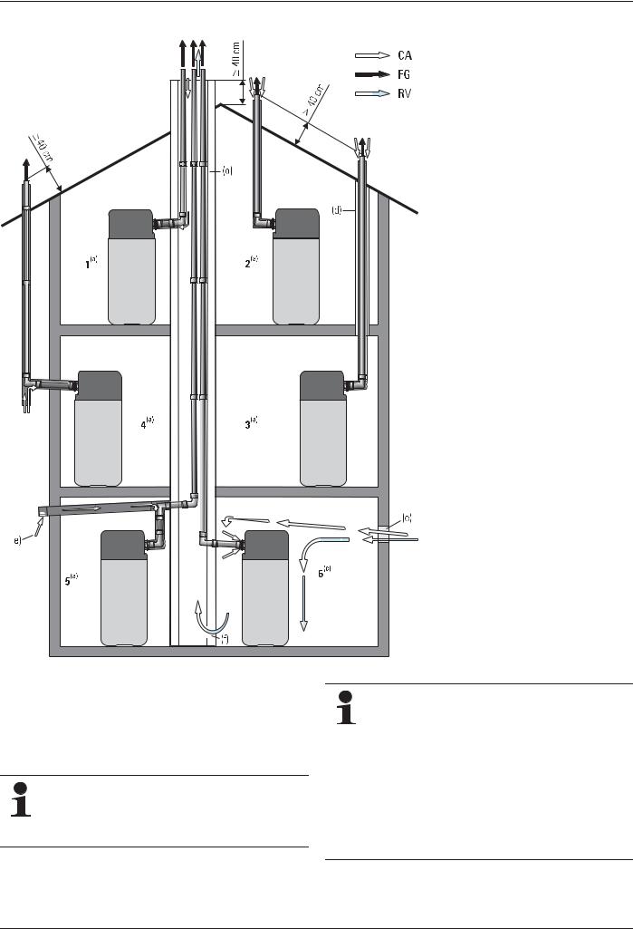
Fig. 4-7 Installation variants for the GCU compact
The ROTEX GCU compact are designed basically for operation independent of the ambient air. They are fitted with a concentric flue gas /air supply pipe DN 60/100.
The SET GCU1 ( 15 50 79.17) kit can be used to flexibly arrange the flue gas /air supply pipe for the connection directions to the rear or upwards and extended to DN 80/125.
In some cases, the resonance in the flue system can amplify the noise at the mouth of the flue gas pipe. The noise level can be effectively reduced with the application of a silencer (E8 MSD,  15 45 78 or E11 MSD,
  15 45 79).
1-6 Different set-ups (For a description, see section 4.2.1 to 4.2.3)
CA Inlet air (combustion air)
FG Flue gas
RV Rear ventilation
aSet up variant for room-air independent operation (flue gas/inlet air concentric)
bSet up variant for limited room-air inde-
pendent operation (flue gas/air inlet separate)
c Set up variant for room-air dependent operation
dLongitudinally ventilated shaft with fire resistance duration of 90 min (in residential buildings with low headroom 30 min).
Observe country-specific regulations for fire-resistance periods!
eVentilation opening (1x150 cm² or 2x75 cm²)
fRear ventilation opening (150 cm²)
Using the ROTEX GCU compact in room-air independent operation with a concentric flue gas/air supply pipe is recommended by ROTEX. If possible, choose this set-up!
In the event of limited room-air independent (separate flue gas/air supply pipes with a single-walled connecting pipe) and in the event of room-air dependent operation, the installation room must have a ventilation opening of at least 150 cm2 into the outdoors.
This reduces the overall energy efficiency of the building in the framework of the European Guideline 2010/31/EU: EPBD.
14 |
ROTEX GCU compact - |
4 Set-up and installation
4.2.1 Operation independent of ambient air
With equipment erection in residential rooms, only one of the set up variants 1 to 4 is permissible.
Set-up version 1
The ROTEX GCU compact with the SET GCU1 and the concentric LAS connection line SET H or SET K is connected to the chimney or an installation shaft.
–The combustible air supply from the outside runs through the chimney or through an installation shaft.
–The flue gas discharge using a flue gas pipe to the outside runs through the same shaft as the air supply.
–Minimum vertical distance between flue gas exit and roof ridge: 40 cm.
Set-up version 2
The ROTEX GCU compact is placed directly below the roof. Connection with SET GCU1 und SET L.
–The combustible air supply and flue gas discharge run through a concentric dual pipe.
–The combustible air supply from the outside runs through the outer ring-shaped gap of the dual tube and the flue gas discharge to the outside runs through the inner tube.
–Minimum vertical distance between flue gas exit and roof surface: 40 cm.
–Minimum height of the flue gas pipe: 2 m.
Set-up version 3
The ROTEX GCU compact is not placed directly below the roof. The dual tube for the combustible air supply and flue gas pipe runs through the roof truss.
–The combustible air supply and the flue gas discharge run through a concentric dual pipe (as in Installation version 2).
–In the area of the roof truss, the dual pipe for the combustible air supply and the flue gas duct must be laid through a protective pipe with sufficient fire resistance or be structurally separated from the roof truss.
Set-up version 4
The ROTEX GCU compact with the SET GCU1 and the LAS connection line SET H or SET K is connected to the exterior wall system SET G.
–The combustible air supply from the outside runs through the ring-shaped gap in the dual pipe, through the outer wall (suction from below).
–The flue gas discharge to the outside runs through a concentric pipe, through the outer wall and then up to at least 40 cm over the roof surface. In the external area, the outer air gap serves as heat insulation for the flue gas pipe.
If the wall feed through has a height of less than one meter above the plot, ROTEX recommends sending the combustible air through a separate air supply pipe (mounting height: about 2 m). W8 ZR,  15 50 79.00
66 or W11 ZR, 15 50 77.00 30
Set-up version 5
If, for constructional or legal/regulatory reasons, the shaft used for the flue gas routing is not suited for sending the combustion air through it at the same time, the combustion air must be sent through a separate line.
If the flue gas connection line to the shaft is double-walled and is surrounded by the combustion air, there are no additional ventilation requirements on the installation room.
–Combustion air inlet is routed from the outside via the adequately sealed inlet air which is connected directly to the concentric exterior pipe of the connection line. The air inlet line should be sized so that the suction resistance at nominal power is less than 50 Pa.
–The connection line between the ROTEX GCU compact and the installation shaft is completely concentric and surrounded by combustion air.
ROTEX GCU compact - |
15 |
4 Set-up and installation
4.2.2 Operation partially independent of ambient air
Alternative to set-up variant 5
The ROTEX GCU compact is operated with separately routed inlet air/ flue gas lines (2 line system).
–Combustion air inlet is routed from the outside via the adequately sealed inlet air through the external wall. The air inlet line should be sized so that the suction resistance at nominal power is less than 50 Pa.
–Flue gas dissipation to the outdoors is via the chimney or an installation shaft. If the connection line between the ROTEX GCU compact and the installation shaft is single-walled or is
not completely surrounded by combustion air, a ventilation opening of at least 150 cm2 is required.
Appropriate measures must be taken to ensure that the burner cannot be operated if the ventilation opening is closed.
–The installation shaft where the flue gas line runs must be rear
ventilated. In the lower area there must be a rear ventilation opening of at least 150 cm2 must be provided.
The cross-section of the installation shaft must be sized so that between the external wall of the flue gas line and the internal face of the installation shaft the following minimum distance must be maintained:
–with a rectangular shaft cross-section: 2 cm
–with round shaft cross-section: 3 cm.
The rear ventilation opening must not be in rooms where a positive pressure is generated (e.g. by controlled apartment ventilation, a tumble-drier etc.).
4.2.3 Ambient air dependent operation Set-up version 6
The ROTEX GCU compact can be connected even with ventilation and air-conditioning. Thereby, only the inner flue gas pipe (plastic pipe Ø 60 mm) of the concentric air-flue gas pipe is connected to the flue gas line. The device sucks the combustible air from the installation room through the ring-shaped gap of the jacket pipe.
For the flue gas routing to the outdoors, the shaft sizing and the rear ventilation, the same conditions apply as in section 4.2.2. A ventilation opening to the outside of 150 cm2 is imperative.
In some cases, the resonance in the flue system can amplify the noise at the mouth of the flue gas pipe. The noise level can be effectively reduced with the application of a silencer (E8 MSD,  15 45 78 bzw.
E11 MSD, 15 45 79).
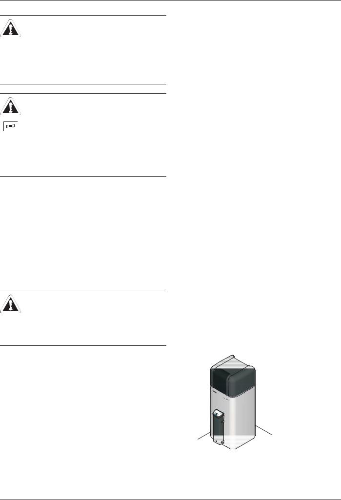
4.3 Transport and delivery
WARNING!
The ROTEX GCU compact is top heavy when not filled, it can tilt over during transport. This can pose a risk to persons or damage the machine.
ƔCorrectly secure the ROTEX GCU compact, transport carefully, use the handles.
The ROTEX GCU compact is delivered on a pallet. All industrial trucks, such as lifting trucks and forklift trucks, are suitable for transporting it.
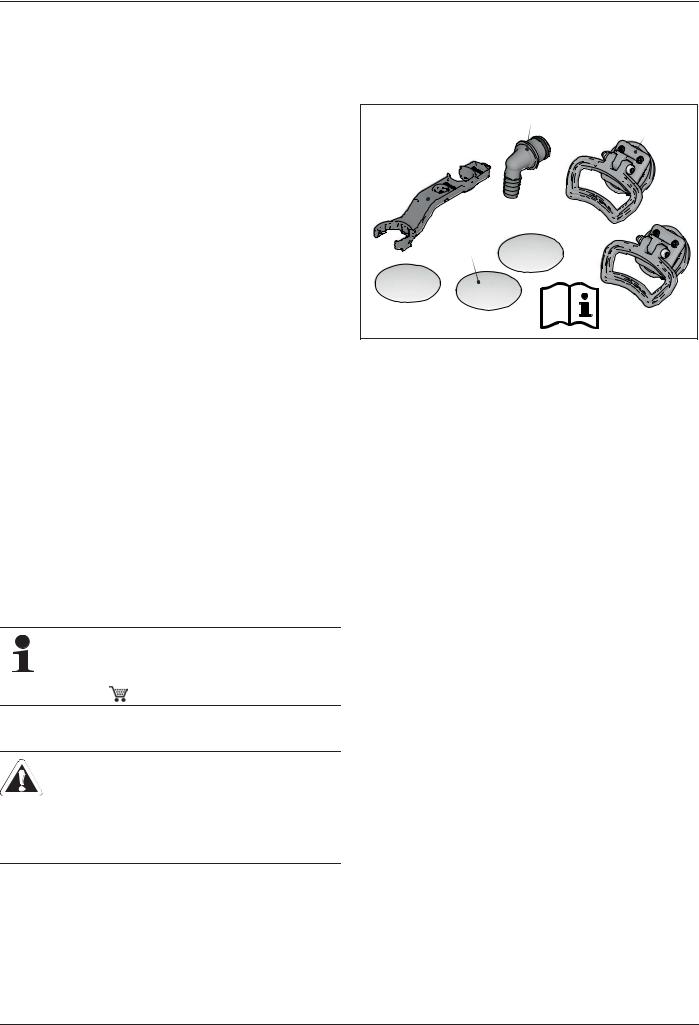
Scope of delivery
–ROTEX GCU compact (preassembled),
–Bag of accessories (see fig. 4-8),
–Outside temperature sensor (RoCon OT1), for weather-con- trolled regulation.
–Document pack.
&[ |
$[ |
'[ |
%[ |
A |
Handles (only required for |
C |
Hose connection piece for |
|
transport) |
|
safety overflow |
B |
Cover screen |
D |
Spanner |
Fig. 4- Contents of bag of accessories
Recommended accessory
–Safety group (SGB GCU compact,  15 70 46) with pressure gauge, safety valve, automatic bleeding, filling cock, connection fittings).
Additional accessories see ROTEX price list.
4.4 Installing the Gas Combi Unit compact
4.4.1 Selecting the installation site
The place of installation for the ROTEX GCU compact must meet the following minimum requirements.
Installation surface
–The base must be level and smooth and have a sufficient ground load-bearing capacity, of 1050 kg/m² plus safety factor. Install a pedestal if necessary.
–Observe the set-up dimensions (see section 4.1).
Installation room
–There are no special conditions for ventilation of the installation room for operation independent of the ambient air (using a concentric air/flue system).
–In the event of limited room-air independent operation and in
the event of room-air dependent operation, the installation room must have a ventilation opening of at least 150 cm2 to the outside. If the flue gas line goes via an installation shaft to the outside, it must be rear ventilated (see section 4.2.2).
–For partial ambient air-independent and for ambient airdependent mode, the installation room must be free from aggressive vapours (e.g. hair spray, perchloroethylene, carbon tetrachloride), heavy dust formation and high atmospheric humidity (e.g. washhouse).
–Outdoor installation is only possible to a limited extent. The storage tank must not be exposed to continuous direct sunlight, as the UV radiation and the effects of the weather will damage the plastic.
–Installation room must be continuously protected from frost.
16 |
ROTEX GCU compact - |
4 Set-up and installation
Surface temperatures, minimum distance
WARNING!
The plastic wall of the storage tank of the ROTEX GCU compact can melt under the effects of external heat (80°C) and, in the extreme case, can catch fire.
ƔOnly install the ROTEX GCU compact with a minimum distance of 1 m to other heat sources (>80°C) (e.g. electrical heater, oil heater, chimney) and the material to be combusted.
CAUTION!
Wird die ROTEX GCU compact is not erected adequately lower the flat solar panels (the top edge of the storage tank is higher than the bottom edge of the solar panels), the unpressurised solar system in the outdoor area will be unable to drain completely.
ƔErect the GCU compact low enough, with a solar connection, with regard to the flat solar panels (observe minimum gradient in the solar connecting lines)
–When operating independently of the ambient air with nominal output, the design does not allow temperatures > 70°C on any component outside the unit panels. Therefore, no minimum distance is required to components made with flammable materials.
–A minimum distance of 50 mm between the flue gas duct and flammable components should be maintained in a partial room air-independent and ambient air-dependent mode (separate flue gas/air intake line).
–Do not use or store easily inflammable and easily combustible substances directly next to the ROTEX GCU compact (minimum distance 1 m, see fig. 4-10).
4.4.2 Setting up the unit
WARNING!
The ROTEX GCU compact is top heavy when not filled, it can tilt over during transport. This can pose a risk to persons or damage the machine.
ƔCorrectly secure the ROTEX GCU compact, transport carefully, use the handles.
Precondition
–The installation site complies with the respective country-spe- cific regulations, as well as the minimum requirements described in section 4.4.1.
Set-up
ƔRemove the packaging and dispose of it in an environmentally sound manner.
ƔUnscrew the threaded inserts (fig. 4-9, item G), onto which the carrier loops are to be attached, from the hot water storage tank.
ƔThread the carrier loops (item A) through the threaded pieces (item G) and mount onto the available connections on the front and back of the hot water storage tank.


Fig. 4-9 Assemble the handles (for legend, see fig. 4-8)
ƔCarefully transport the ROTEX GCU compact to the erection site, use the handles.
ƔInstall ROTEX GCU compact at the place of installation.
–Recommended distances:
to the wall (s1/s2/s3/s4): see tab. 4-1 To the ceiling (sD): 150 mm.
–Install close to the discharge point.
 K5
K5
V 
 V V
V V
Fig. 4-10 Minimum distances for the erection of the GCU compact (for dimensions, see tab. 4-1)
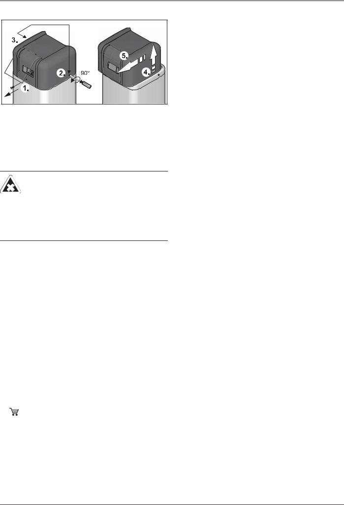
Ɣ Install the connection lines to allow for the removal of the sound insulation hood (fig. 4-11).
ROTEX GCU compact - |
17 |
4 Set-up and installation
4.4.3 Remove the sound insulation hood
Fig. 4-1 Unscrew/loosen screws, lift the cover at the back and remove in a forwards direction.
4.5 Air/flue system (LAS)
4.5.1 General instructions for flue system
WARNING!
There will be a risk of poisoning caused by flue gas escaping within enclosed rooms that are inadequately ventilated.
ƔInstall only approved flue gas systems.
ƔThe stipulated ventilation and rear ventilation must be ensured, depending on the set up variant.
ƔCoverings of the flue gas mouth are not allowed.
Minimum requirements
Observe country-specific regulations and EN 15287 for the design and measurement of the flue gas system.
Basically, for the flue gas system, you can use each flue gas pipe according to EN 14471 with EU label, which meets the following minimum requirements:
–Suitable for gas.
–Suitable for flue gas temperatures of at least 120°C (temperature class T120 or higher).
–Suitable for at least 200 Pa overpressure (pressure class P1 or H1).
–Humidity-resistant (condensation resistance class W).
–Sufficiently corrosion-resistant (corrosion resistance class 1 or 2).
The properties of the flue gas system must be identifiable on the installed system (nameplate in the installation room).
Type of connections
–Directly backwards (fig. 4-1: SET H,  15 50 79.08).
–At the side towards the back (fig. 4-2: SET K,  15 50 79.09).
–Direct roof penetration (fig. 4-7, variant 2 and 3: SET L, 15 50 79.10).
For other details and connection dimensions for the three versions of the flue gas pipe, see section 4.5.3.
–Each flue gas line must be installed with a suitable test adapter for checking and setting the combustion values. The
ROTEX LAS construction sets each include a test adapter
(D8PA,  15 50 79.00 93).
Installation position and line height
–The maximum permitted flue gas counter pressure is 200 Pa. The pressure loss in the supply line must not exceed 50 Pa.
–Angle of entry of the flue gas pipe into the chimney or installation shaft: at least 3°.
–Slope for horizontal parts of the flue gas pipe: at least 3°. Counter-slopes are not allowed at any point in the flue gas pipe.
–If the flue gas duct needs more than 3 deflections >45° for the flue gas duct, the maximum height for the flue gas duct reduces by at least 1 m per deflection (flue gas calculations may be needed).
–If the horizontal connecting piece is extended, the maximum permitted height of the flue gas pipe is reduced by exactly that length.
–Flexible flue gas lines must not be used in horizontal connection sections.
Flue gas system resistance
For a safe burner start and stable flue gas values in the lower output range, a minimum resistance in the flue gas line is necessary, especially for liquid gas units.
After the initial burner start, the ROTEX GCU compact switches at first into the storage tank charging mode. In this mode, the burner blower runs with max. speed.
ƔSwitch the burner on (see chapter 15.2 "Emissions measurement").
ƔMeasure the resistance with a differential pressure measurement unit on the flue gas measurement location between the flue gas and intake air measurement openings (differential pressure for the ROTEX GCU compact at least 0.45 mbar).
ÎIf the differential pressure is not reached when the burner
blower is at maximum speed, a silencer will need to be fitted (E8 MSD,  15 45 78 or E11 MSD,
  15 45 79)
The tab. 4-2 shows the maximum permissible height of the flue gas line to ensure that the ROTEX GCU compact can be operated in the rated power range.
|
Max. permissible height of the flue |
||||
Installation |
|
|
gas line ) |
|
|
version |
|
GCU compact |
|
||
(according to |
315 / 515 |
|
324 / 524 |
|
533 |
|
|
||||
fig. 4-7) |
|
|
|||
|
|
|
|
|
|
11), 2, 3, 4 |
123) |
|
153) |
|
193) |
5, 6 |
253) |
|
273) |
|
293) |
1)Shaft cross-section at DN80: 135 mm x 135 mm
) |
Concentric flue gas-/supply line: DN80/125 |
|
Design for natural gas (G20) |
Tab. 4-2 Maximum height for the flue gas duct in m
The characteristics for the flue gas calculation can be obtained from fig. 4-12 and chapter 15.1 "Data for designing the flue gas pipe".
18 |
ROTEX GCU compact - |
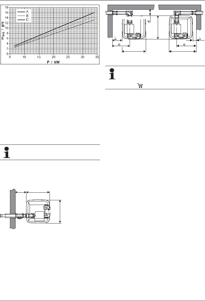
4 Set-up and installation
a |
A |
Natural gas E/H (G20) |
mET |
Flue gas mass flow |
B |
Natural gas LL/L (G25) |
P |
Burner load |
C |
Liquid gas |
|
|
Fig. 4-12 Flue gas mass flow in dependence of the burner load ROTEX GCU compact (all types)
The flue gas mass flow of the plant depends on the burner output of the ROTEX GCU compact.
4.5.2 Connecting a flue gas line Requirements
–The flue system fulfils the requirements described in section 4.5.1.
–The flue system fulfils any other required national or regional safety requirements.
–The ROTEX GCU compact is installed correctly.
Connection
We recommend to use the associated ROTEX LASsets (see fig. 4-15). They satisfy all requirements and are also fitted with special acid-proof seals.
ƔConnect the ROTEX GCU compact to the flue gas system inside the installation room (fig. 4-1 / fig. 4-2).
For dimensions, see tab. 4-1.
ƔPlace the nameplate of the flue gas pipe in the installation room.
 V W
V W


 A Z
A Z
<![endif]>

 V
V
|
|
<![if ! IE]> <![endif]>W |
|
V |
|
|
V |
V |
A |
A |
V |
|
Z |
Z |
|
Fig. 4-14 Plan view GCU compact Flue gas connection to the side with SET K (see section 4.5.3) - (for dimensions, see tab. 4-1)
In some cases, the resonance in the flue system can amplify the noise at the mouth of the flue gas pipe. The noise level can be effectively reduced with the application of a silencer (E8 MSD,  15 45 78 bzw.
E11 MSD, 15 45 79).
Fig. 4-13 Plan view GCU compact Flue gas connection to the rear with SET H (see section 4.5.3) - (for dimensions, see tab. 4-1)
ROTEX GCU compact - |
19 |

4 Set-up and installation
4.5.3 Flue gas system kits
<![endif]>
6(7 / |
|
|
|
:$ |
|
|
|
|
|
|
|
|
: :+ |
PP |
|
||
|
|
|
|
|
|
|
|
: :+9 |
PP |
|
|
|
|
|
|
|
|
|
|
|
|
||
|
|
: :+9 |
PP |
|
|
|
|
|
|
|
|
|
|
: :+9 |
PP |
|
|
|
|
|
|
|
|
|
|
: :.9 |
PP |
|
|
|
|
|
|
|
|
|
|
|
|
||
|
|
: :.9 |
PP |
|
|
|
|
|
|
|
|
|
|
: :.9 |
PP |
|
|
|
[[[ |
|
|
|
|
|
|
|
|
|
|
6(7 / |
|
|
|
|
|
|
|
|
6(7 /;;; |
||
|
|
|
|
|
;;; |
|
|
|
' )' |
|
|
|
|
|
|
|
|
|
|
|
' 6' 6 |
|
|
|
|
|
|
|
|
|
|
|
' 6' 6 |
|
|
|
|
|
|
|
|
|
|
|
' 6' 6 |
|
|
|
|
|
|
|
|
|
|
|
' )' |
|
|
|
|
|
|
|
|
6(7 *


( =5


 :$
:$
|
|
|
[ |
<![endif]>


 [
[
: =5


3$


6(7 .


6(7 (


|
|
|
|
|
|
|
|
|
3$ |
|
|
|
|
|
|
|
|
|
|
|
|
|
|
|
|
|
|
|
|
|
( 06' |
|
|
|
|
|
|||
|
|
|
|
|
|
|
|
|
|
|
|
|
|
|
|
|
|
|
|
V / |
|
||
|
|
|
|
|
|
||
|
|
|
|
|
V 5 |
|
|
V |
|
V |
/ |
V |
5 |
|
|
|
6(7 *&8 |
+ |
|
|
|
|
|
|
|
6(7 + |
|
|
|
|
|
|
|
|
3$ |
|
|
|
|
|
|
|
|
|
V + |
|


<![endif]>


 ( 55
( 55 


Fig. 4-15 Flue system kits |
* |
If needed |
(L) |
Flue gas connection left |
|
** |
See tab. 4-1 |
(R) |
Flue gas connection right |
|
|
|
(H) |
Flue gas connection rear |
20 |
ROTEX GCU compact - |
 Loading...