


 Loading...
Service Source
Apple Studio Display 17" LCD
(ADC)
Updated 6 Decenber 2004
© 2003 Apple Computer, Inc. All rights reserved.
Service Source
Take Apart
Apple Studio Display 17" LCD (ADC)
© 2003 Apple Computer, Inc. All rights reserved.
General Information
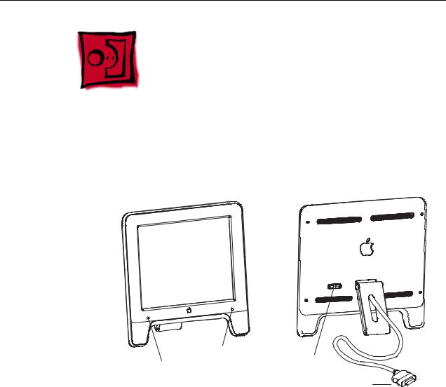
Overview
Front View |
Rear View |
Power On/Off Button
Launch Button |
USB Ports |
|
|
|
ADC Connector |
Note:
The Launch Button brings up the Apple Display preferences window. The Power Button turns the display on and off.
Identifying Versions of the Display
There are two versions of the display and although there are no specification differences, in some cases the service part will be different.
The versions can be identified as follows:
•Version A has a blue-gray logo (front and back).
•Version B has a silver logo (front and back) and a hinge that allows the foot to collapse to flat.
Note: Both version A and B have flexible hinges, the difference is that the version B hinge will collapse flat, parallel to the screen, to facilitate packing.
General Information |
Apple Studio Display 17" LCD Take Apart - 1 |

Tools
The following tools are recommended for the take apart procedures.
•Cotton gloves (922-1592)
•Hex key set, metric
•Phillips #1 screwdriver
•Volt meter (for troubleshooting)
•Black stick (nylon probe tool 922-5065) or other ESD-safe, non-marring tool
•ESD wriststrap and mat
Before Working on the Display
Warning: There is a risk of electric shock, fire or other hazard, if the Inverter Board, ADC Cable, MLB to USB Socket Cable, and the LCD Display Module are not replaced with the correct Apple service part.
Warning: Unless otherwise instructed in the service procedures, to avoid the risk of electric shock, fire or other hazard, disconnect the ADC connector from the computer to ensure that the display is not receiving power during service.
Important:
•The display LCD and the inside and outside of the case can scratch and retain fingerprints easily.
•Use clean soft cotton gloves when working on the display.
•Only rest the LCD screen and case parts on a soft clean surface.
•If available, place a protective film over the display to protect it from scratches or nicks.
•Remove all jewelry that could scratch or damage the display or plastic housing.
•Do not press on the LCD display panel or its edges as damage can result.
•Do not expose the display to high temperature or humidity.
•Do not expose the display to direct sunlight.
•Follow ESD safe procedures to avoid circuit damage. Use a grounded wrist strap.
General Information |
Apple Studio Display 17" LCD Take Apart - 2 |

Procedure
FOOT REMOVAL
1.Remove three hex key screws (a).
2.Remove Foot and Hinge Cap.
Screw part number:
(a) 922-5551
(a)
REAR COVER, EMI SHIELD, BEZEL,
AND USB COVER REMOVAL
1. |
Remove four hex key screws (Rear Cover) (a). |
|
2. |
Remove Rear Cover and Rear Shield. |
(a) |
3. |
Remove screw (b). |
|
4. |
Separate the USB Cover. |
|
5.Peel back Vent Labels if needed to release EMI Shield.
6.Slide the EMI Shield to disengage it
from the Chassis, then remove.
7. Remove the Vertical and Horizontal Clips from the Cradle assembly. Note: The Clips can crack or break. Use care when removing.
A black stick or flat-blade screwdriver may be helpful.
8.Separate the Bezel assembly from the LCD panel assembly.
Cradle
Clips
Screw part numbers:
(a)922-5965
(b)922-5560
(a)
(a)
|
(a) |
|
USB |
(b) |
Cover |
|
Clips
Bezel
General Information |
Apple Studio Display 17" LCD Take Apart - 3 |
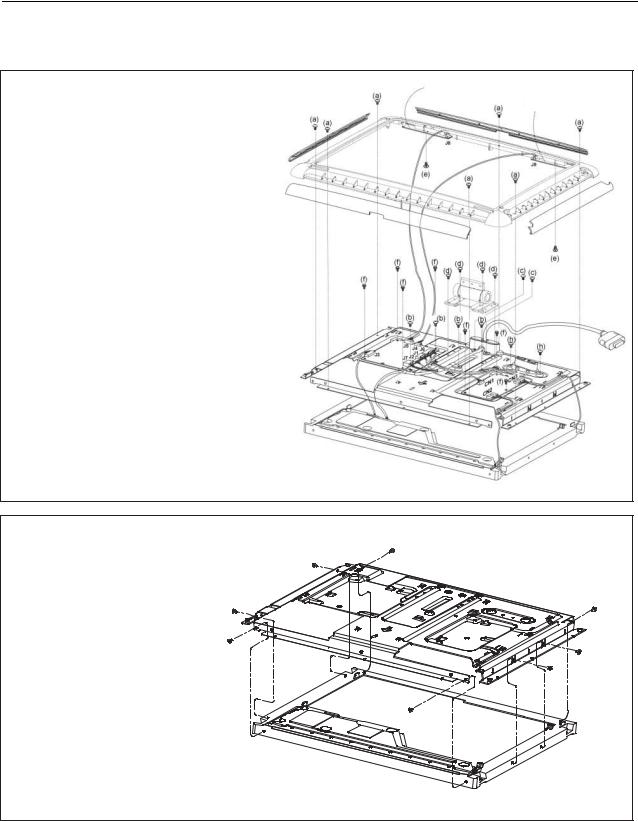
CRADLE, CHASSIS, LCD DISPLAY,
MAIN BOARD & INVERTER BOARD REMOVAL
1.Remove seven screws (a).
2.Disconnect J7, J2, J1, J6, J4, J5, J3, CN1, CN2, CN3 from the Main Board.
3.Remove seven screws (f).
4.Remove the Main Board and Inverter Board.
5.Remove four screws (b) & two screws (h).
6.Remove the USB Connector.
7.Remove four screws (d).
8.Remove the Hinge.
9.Remove two screws (c).
10.Remove the Main ADC Cable.
11.Disconnect the cables from the Touch Switches.
12.Remove two screws (e).
13.Remove the Touch Switches.
Screw part numbers:
(a)922-5560
(b)922-5560
(c)922-5560
(d)922-5620
(e)922-5553
(f)922-5554
(h)922-5560
Touch Switch
Touch Switch
CHASSIS AND LCD PANEL REMOVAL |
|
||
1. |
Remove eight screws (a). |
(a) |
|
2. |
Peel back Vent Label and Shielding Tape, |
(a) |
|
|
as needed, to release the Backlight Bulb |
|
|
|
wires. |
(a) |
|
3. |
Separate the Chassis and (a) |
||
|
|||
LCD panel.
Screw part number:
(a) 922-5555
(a) 


(a)
(a)
(a) 


General Information |
Apple Studio Display 17" LCD Take Apart - 4 |
Loading...