


 Loading...
K Service Source
Apple Two-Page Mono
Monitor
K Service Source
Basics
Two-Page Monochrome Monitor
Basics |
Monitor Distortion - 1 |
|
|
|
|
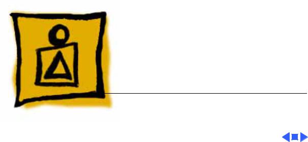
Monitor Distortion
Overview
All large-screen monitors are susceptible to distortions caused by environmental conditions.
Ideal Raster These distortions are usually not visible on monitors with smaller screens.
Raster Shifted Up |
Raster Shifted Right |
and Left |
|

Basics |
Monitor Distortion - 2 |
|
|
|
|
|
Important: Even monitors |
|
|
set to factory specifications |
|
|
may appear distorted when |
|
|
set up in a new environment. |
|
|
Common environmentally- |
|
|
caused distortions are shown |
|
|
on this and the following |
|
|
cards. Always check first for |
|
|
environmental causes before |
|
|
attempting to repair or |
|
|
adjust a monitor with a |
|
|
distorted raster. |
|
Basics |
Monitor Distortion - 3 |
|
|
|
|
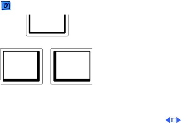
Environmental
Influences
The following environmental conditions may distort the raster of a Two-Page Monochrome Monitor:
• Proximity to metal objects, such as metal
Right Edge Not Straight desks, file cabinets, and bookshelves. Metal objects affect the earth’s magnetic field. Earth magnetism usually distorts only the edges of the screen.
Left Side Bowed Out |
Right Side Bowed In |

Basics |
Monitor Distortion - 4 |
|
|
|
|
• |
Fluorescent lights, other |
|
|
monitors, or electronic |
|
|
appliances such as coffee |
|
|
makers and copy |
|
|
machines. These objects |
|
|
cause dynamic raster |
|
|
distortion, that is, |
|
|
movement or jitter of the |
|
|
image. |
|
Basics |
Monitor Distortion - 5 |
|
|
|
|
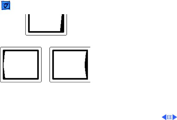
Upper-Right Corner Rounded
Left Edge S-Shaped |
Raster Tilted Right |
Troubleshooting
Important: Module swapping cannot fix a monitor with environmental distortion problems, and adjusting a monitor with such problems alters the factory settings.
Note: If the monitor has shifted up/down or right/ left only, adjust it using the centering controls. If you then move the monitor, you may need to readjust the centering controls.

Basics |
Monitor Distortion - 6 |
|
|
|
|
|
Before adjusting a monitor |
|
|
with a distorted raster, try |
|
|
the following: |
|
|
• Swivel or move the |
|
|
monitor, or |
|
|
• Remove the monitor from |
|
|
the building and recheck |
|
|
it in another location. |
|
|
If the display changes (for |
|
|
better or worse) when you |
|
|
move it to another location, |
|
|
the environment is the |
|
|
source of the problem. |
|
|
Relocate the monitor or |
|
|
remove the distortion- |
|
|
causing object. |
|

Basics |
Monitor Distortion - 7 |
|||
|
|
|
||
|
If the display does not change |
|||
|
when you move the monitor |
|||
|
to another location, |
|||
|
continue troubleshooting |
|||
|
the problem (refer to |
|||
|
Troubleshooting/Symptom |
|||
|
Charts). |
|||
|
|
|
|
|
|
|
|
|
|
K Service Source
Specifications
Apple Two-Page Monochrome
Monitor
Specifications |
Characteristics - 2 |
|
|
|
|
Picture Tube
Screen Resolution
Scan Rates
Characteristics
21-in. diagonal screen (20-in. viewable image) Phosphor EIA Type P4 (white)
Flat, square, high-contrast, antiglare surface
1,152 x 870 lines; 77 dpi
Displays up to 16 grays with 512K of video RAM
Vertical refresh rate: 75 Hz
Horizontal scan rate: 68.7 kHz
Dot clock: 100 MHz

|
Specifications |
Characteristics - 3 |
|||
|
|
|
|
||
Active Video |
15 in. by 11.3 in. |
||||
Display Area |
(381 mm by 287 mm) |
||||
Input Signal |
Video: analog; RS–343 standard |
||||
|
|
|
|
|
|
|
|
|
|
|
|

Specifications |
Controls - 4 |
|
|
|
|
Controls
User Controls
Rear panel: power switch
Right side: brightness and contrast controls

Specifications |
Physical and Electrical - 5 |
|
|
|
|
Physical and Electrical
Power Supply
Universal power supply
Voltage: 90–270 VAC, self-configuring Frequency: 47–63 Hz
Power: 95 W maximum
Size and Weight
Height: 15.7 in. (399 mm)—add 3.2 in. (81 mm) for integrated stand
Width: 19.5 in. (495 mm) Depth: 17.4 in. (442 mm) Weight: 55 lb. (25 kg)
Monitor Stand |
Integrated, tilt-and-swivel stand |
|
|
|
|
|
|
|

|
Specifications |
Operating Environment - 6 |
|||
|
|
|
|
||
|
|
Operating Environment |
|||
Temperature |
50°F–95°F (10°C–35°C) |
||||
Humidity |
90% maximum, noncondensing |
||||
Altitude |
10,000 ft. (3,048 m) maximum |
||||
|
|
|
|
|
|
|
|
|
|
|
|

K Service Source
Troubleshooting
Apple Two-Page Monochrome
Monitor

|
Troubleshooting |
General/ - 1 |
|
|
|
|
|
|
|
|
|
General
The Symptom Charts included in this chapter will help you diagnose specific symptoms related to your product. Because cures are listed on the charts in the order of most likely solution, try the first cure first. Verify whether or not the product continues to exhibit the symptom. If the symptom persists, try the next cure. (Note: If you have replaced a module, reinstall the original module before you proceed to the next cure.)
If you are not sure what the problem is, or if the Symptom Charts do not resolve the problem, refer to the Flowchart for the product family.
For additional assistance, contact Apple Technical Support.

 Troubleshooting Symptom Charts/No Raster - 2
Symptom Charts
No Raster
No raster, LED off |
1 |
Check AC power cord connections. |
|
|
2 |
Check internal power connectors. |
|
|
3 |
Replace blown fuse. |
|
|
4 |
Replace power supply. |
|
|
5 |
Replace on/off switch filter assembly. |
|
|
6 |
Replace deflection board. |
|
No raster, LED on |
1 |
Adjust brightness and contrast knobs. |
|
|
2 |
Verify that video card in computer is working properly. |
|
|
3 |
Check power supply and deflection board connections. |
|
|
4 |
Check CRT socket connectors. |
|
|
5 |
Replace video board. |
|
|
6 |
Replace deflection board. |
|
|
7 |
Replace CRT and yoke assembly. |
|
|
|
|
|
|
|
|
|

 Troubleshooting Symptom Charts/Geometry - 3
Geometry
Raster size too short, |
1 |
Adjust horizontal-size and vertical-size controls. |
||
tall, narrow, or wide |
2 |
Replace deflection board. |
||
|
3 |
Replace CRT and yoke assembly. |
||
Raster not centered |
1 |
Verify that distortion is not due to environmental conditions. |
||
|
|
Move monitor to another location. |
||
|
2 |
Adjust horizontal-shift and vertical-shift controls. |
||
|
3 |
Replace video board. |
||
Bad vertical linearity |
1 |
Adjust vertical linearity control. |
||
|
2 |
Replace deflection board. |
||
Bad horizontal |
1 |
Adjust horizontal linearity control. |
||
linearity |
2 |
Replace deflection board. |
||
|
|
|
|
|
|
|
|
|
|

 Troubleshooting Symptom Charts/Synchronization - 4
Synchronization
Single horizontal or |
1 |
Check yoke connectors. |
||
vertical line appears |
2 |
Check CRT socket connectors. |
||
on screen |
3 |
Replace deflection board. |
||
|
4 |
Replace CRT and yoke assembly. |
||
Picture breaks into |
1 |
Connect another monitor to computer. Switch on monitor to |
||
diagonal lines |
|
verify that computer produces video signal. |
||
|
2 |
Check connections between video board and deflection board. |
||
|
3 |
Replace deflection board. |
||
|
4 |
Replace video board. |
||
Picture rolls |
1 |
Verify that video card in computer is working properly. |
||
vertically |
2 |
Check connections between video board and deflection board. |
||
|
3 |
Replace deflection board. |
||
|
4 |
Replace video board. |
||
|
|
|
|
|
|
|
|
|
|
 Troubleshooting Symptom Charts/Video - 5
Video
Picture is too dark or |
1 |
Adjust contrast and brightness knobs. |
too bright |
2 |
Verify that video card in computer is working properly. |
|
3 |
Check connection between contrast/brightness assembly and |
|
|
video board. |
|
4 |
Perform video adjustments. |
|
5 |
Replace video board. |
|
6 |
Replace contrast/brightness assembly. |
|
7 |
Replace CRT and yoke assembly. |
Contrast/brightness |
1 |
Check connection between contrast/brightness assembly and |
unadjustable |
|
video board. |
|
2 |
Replace contrast/brightness assembly. |
|
3 |
Replace video board. |
|
4 |
Replace deflection board. |
|
5 |
Replace CRT and yoke assembly. |

|
Troubleshooting |
|
Symptom Charts/(Continued) - 6 |
||
|
|
|
|||
|
|
(Continued) |
|||
Out of focus |
1 |
Check CRT socket connectors. |
|||
|
|
2 |
Check connections between video board and deflection board. |
||
|
|
3 |
Perform focus adjustment. |
||
|
|
4 |
Check screen brightness with a light meter. If reading is |
||
|
|
|
“10” or higher, perform the cutoff and screen luminance |
||
|
|
|
adjustments. |
||
|
|
5 |
Replace video board. |
||
|
|
6 |
Replace deflection board. |
||
|
|
7 |
Replace CRT and yoke assembly. |
||
|
|
|
|
|
|
|
|
|
|
|
|

 Troubleshooting Symptom Charts/Miscellaneous - 7
Miscellaneous
Picture jitters or |
1 |
Check all grounding cable connections. |
||
flashes |
2 |
Confirm that adjacent computer equipment is properly |
||
|
|
grounded. Move electrical devices away from the monitor and |
||
|
|
temporarily shut off all fluorescent lights. |
||
|
3 |
Check connections between video board and deflection board. |
||
|
4 |
Replace deflection board. |
||
At a resolution of |
Note: This symptom occurs with Power Macintosh 9600 |
|||
1152x870, jitter or |
computers using an Apple/IMS video card with any display set at |
|||
a wavy image appears |
1152x870 screen resolution. The computer and the display are |
|||
on right side, left |
working properly. However, video cards with serial numbers |
|||
side, or entire screen |
lower than Fx705xxx should be replaced. Apple’s service stock |
|||
|
has been inspected and upgraded, so replacement video boards |
|||
|
should not exhibit this symptom. |
|||
|
Check the serial number on the video card. If it is lower than |
|||
|
Fx705xxx, replace the video card with a new one (Apple service |
|||
|
part number 661-1409). |
|||
Black spots on screen |
Replace CRT. |
|||
(burnt phosphors) |
|
|
|
|
|
|
|
|
|
|
|
|
|
|

 Troubleshooting Symptom Charts/Monitor Stand - 8
Monitor Stand
Monitor stand does not |
1 |
Verify that “Front” indicator on tilt/swivel mechanism |
||
swivel |
|
aligns with “Front” indicator on base of monitor stand. |
||
|
2 |
Verify that snap lock assembly on bottom of monitor stand is |
||
|
|
in place. |
||
Monitor stand does not |
1 |
Verify that plastic plug is in snap lock assembly. |
||
tilt |
2 |
Verify that snap lock assembly on bottom of monitor stand is |
||
|
|
in place. |
||
|
|
|
|
|
|
|
|
|
|

K Service Source
Take Apart
Apple Two-Page Monochrome
Monitor
Take Apart |
Swivel Stand - 1 |
|
|
|
|
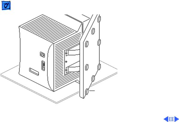
Swivel Stand
No preliminary steps are required before you begin this procedure.
Note: Remove the tiltswivel stand before you remove the CRT.
1 Tilt the monitor onto its left side.
2 Slide the monitor stand forward toward the bezel.
Swivel Stand
Take Apart |
Swivel Stand - 2 |
|
|
|
|
|
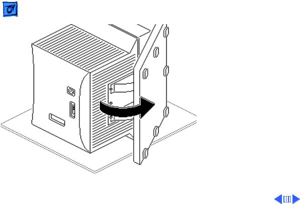
3 With one hand, slightly |
|
|
lift up the monitor and |
|
|
rotate the base of the |
|
|
stand until you can reach |
|
|
the three screws that |
|
|
secure the stand to the |
|
|
chassis. |
|
Take Apart |
Swivel Stand - 3 |
|||
|
|
|
|
|
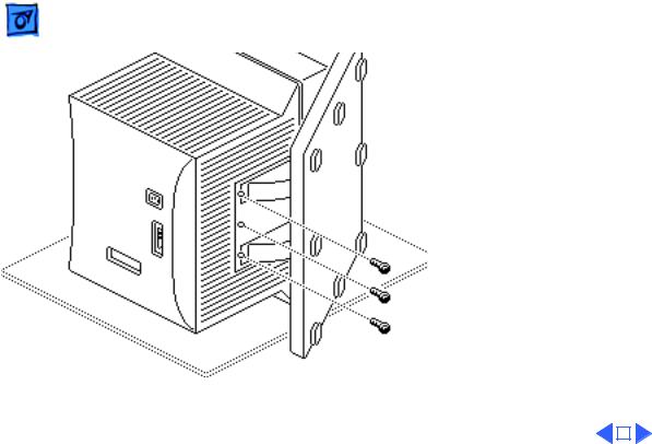
4 |
Remove the three |
|||
|
mounting screws. |
|||
5 |
Slide the monitor stand |
|||
|
back and remove it from |
|||
|
the chassis. |
|||
|
|
|
|
|
|
|
|
|
|

Take Apart |
Rear Cover - 4 |
|
|
|
|
Rear Cover
No preliminary steps are required before you begin this procedure.
±Warning: This product contains high voltage and a high-vacuum picture tube. To prevent serious injury, review CRT safety in Bulletins/Safety.
1 Remove the four cover mounting screws.
2 Pull the rear cover off the bezel.
Rear Cover
 Take Apart
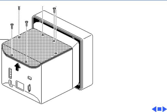
Access
Cover
Access Cover - 5
Access Cover
Before you begin, remove the rear cover.
±Warning: This product contains high voltage and a high-vacuum picture tube. To prevent serious injury, review CRT safety in Bulletins/Safety.
1Remove the six mounting screws and lockwashers that hold the access cover in place.
2Lift the access cover off the chassis.
Loading...