


 Loading...
Shake 4
New Features
Apple Computer, Inc.
© 2005 Apple Computer, Inc. All rights reserved.
Under the copyright laws, this manual may not be copied, in whole or in part, without the written consent of Apple. Your rights to the software are governed by the accompanying software license agreement.
The Apple logo is a trademark of Apple Computer, Inc., registered in the U.S. and other countries. Use of the keyboard Apple logo (Option-Shift-K) for commercial purposes without the prior written consent of Apple may constitute trademark infringement and unfair competition in violation of federal and state laws.
Every effort has been made to ensure that the information in this manual is accurate. Apple Computer, Inc. is not responsible for printing or clerical errors.
Apple Computer, Inc. 1 Infinite Loop
Cupertino, CA 95014-2084 408-996-1010 www.apple.com
Apple, the Apple logo, Final Cut, Final Cut Pro, FireWire, Mac, Macintosh, Mac OS, Nothing Real, QuickTime, Shake, and TrueType are trademarks of Apple Computer, Inc., registered in the U.S. and other countries. Exposé and Finder are trademarks of Apple Computer, Inc.
Adobe is a trademark of Adobe Systems Inc.
Cineon is a trademark of Eastman Kodak Company.
Maya, Alias, Alias/Wavefront, and O2 are trademarks of SGI Inc.
3ds Max is a trademark of Autodesk Inc.
Softimage and Matador are registered trademarks of Avid Technology, Inc.
Times is a registered trademark of Heidelberger Druckmaschinen AG, available from Linotype Library GmbH.
Other company and product names mentioned herein are trademarks of their respective companies. Mention of third-party products is for informational purposes
only and constitutes neither an endorsement nor a recommendation. Apple assumes no responsibility with regard to the performance or use of these products.

Contents
Preface |
5 |
About the New Features in Shake 4 |
|
5 |
Changes to the Shake Documentation |
|
6 |
Summary of New Features |
Chapter 1 |
9 |
Interface Enhancements |
|
9 |
Saving Favorite Views |
|
11 |
Enable/Disable Local File Paths |
|
11 |
Directories Saved to the Favorites List Are Permanent |
|
12 |
Locking Parameters |
|
12 |
A Next Button to Create Additional Local Variables |
|
12 |
The Console Tab |
|
13 |
New Global Parameters |
|
19 |
Resizing the Node Overview |
|
20 |
New Ways of Adding and Connecting Nodes |
|
23 |
Cloned Node Naming |
|
23 |
Monitor Calibration With Truelight |
|
24 |
Updated Onscreen Controls for Transform Nodes |
Chapter 2 |
29 |
Major Features and New Nodes |
|
31 |
Using Shake With Final Cut Pro 5 |
|
36 |
New Adaptive Method for Retiming |
|
38 |
Remastering Media Options in the FileIn Node |
|
42 |
The Cache Node |
|
47 |
New Parameter in the Mask Subtree of Nodes |
|
47 |
New Features for RotoShape Nodes |
|
51 |
The SmoothCam Node |
|
58 |
The AutoAlign Node |
|
69 |
The LensWarp Node |
3
Chapter 3 |
73 |
Compositing With the MultiPlane Node |
|
73 |
An Overview of the MultiPlane Node |
|
75 |
Using the Multi-Pane Viewer Display |
|
81 |
Connecting Inputs to a MultiPlane Node |
|
82 |
Using Camera and Tracking Data From .ma Files |
|
88 |
Transforming Individual Layers |
|
94 |
Attaching Layers to the Camera and to Locator Points |
|
100 |
Parameters in the Images Tab |
|
105 |
Manipulating the Camera |
4 |
Contents |
|
|

About the New Features
in Shake 4
Preface
This document covers all of the new features and enhancements introduced in Shake 4.
If you are already familiar with previous versions of Shake, this document lets you focus on the extensive new enhancements and additions.
Note: All of information in this document is duplicated from the Shake 4 User Manual included in your Shake box and available in PDF-format from the Shake Help menu.
Changes to the Shake Documentation
The print and onscreen (PDF-format) documentation has been completely reorganized and expanded from prior versions.
User Manual
The user manual has been divided into more chapters to make topics easier to find in the table of contents and in the bookmarks drawer of the onscreen PDF. In addition, the documentation of many prior features has been expanded.
Node Reference Guide
Scripting and variables documentation for each of Shake’s functions, previously located in the user manual, has been moved to a new document: the Shake 4 Node Reference Guide, accessible from the Shake Help menu.
The Cookbook
The Cookbook—a popular collection of tips and techniques for improving your workflow in Shake—has been relocated from the tutorials book to to the last chapter of the user manual. What’s more, content from the Cookbook has been integrated into the rest of the manual, where appropriate, to make these topics more accessible.
5
Summary of New Features
This section summarizes the new features that appear in this document.
Topics in Chapter 1
•You can open two scripts at once using the Shake graphical user interface.
•You can save and restore favorite views in each Shake interface area.
•You can enable the ability to use relative paths in the File Browser.
•Favorite directories in the File Browser are now saved automatically.
•There are now lock controls for each parameter.
•There is a new “next” button when you create local variables, which makes it easier to create many variables at a time.
•A new console tab lets you view the contents of the console from within Shake.
•New global parameters provide additional ways to control new features.
•An enhanced Node View provides options for visualizing animated nodes, expression links, node concatenation, and noodle color coding and stippling.
•You can now resize the node overview.
•There are four new ways of adding and connecting nodes to a node tree.
•Cloned nodes are now named differently.
•Truelight monitor calibration software is included, which also provide a new Viewer lookup table (VLUT) option for the Viewer.
•The onscreen controls for transform nodes have been updated, with additional hot keys.
Topics in Chapter 2
•Shake now supports the OpenEXR format.
•There is new support for clips and sequences sent from Final Cut Pro 5 to Shake 4.
•New adaptive retiming options in the FileIn node use optical flow technology to create smooth motion retiming.
•New remastering options in the FileIn node use optical flow technology to deinterlace, change frame rates, and rescale images for high-quality format conversion.
•A new Cache node lets you specify key points to be cached in your node tree.
•A new clampMask parameter in the mask subtree of nodes lets you clamp mask image data to a value between 0 and 1.
•The RotoShape node has new features, including:
•The ability to copy and paste shapes between compatible nodes.
•The ability to cut and paste rotoshape keyframes.
•Controls to retime shape keyframes
•New commands for attaching trackers to individual shape control points.
•The ability to import and export shape data.
•The SmoothCam node automatically smooths or locks camera motion in a shot.
6 |
Preface About the New Features in Shake 4 |
|
|
•The AutoAlign node uses advanced image processing to align up to three input images with one another, automatically.
•The LensWarp node provides calibration tools to correct for lens distortion, or to match the lens distortion from one shot in another.
Chapter 3
•Chapter 3 contains complete documentation for the MultiPlane node, which provides the ability to do the following:
•Composite background or foreground elements against a moving background plate using 3D camera tracking data.
•Arrange multiple layers within a 3D coordinate space for easy simulation of perspective, parallax, and other depth effects.
Preface About the New Features in Shake 4 |
7 |
|
|
Interface Enhancements |
1 |
|
This chapter covers general enhancements throughout the Shake interface.
Opening Two Scripts at Once
Shake is designed to have only one script open at a time. Typically, each script is used to create a single compositing project, with a single frame range and a single node tree. Although Shake supports multiple independent node trees within the same script, all trees share the same duration, defined by the timeRange parameter in the Globals tab.
If necessary, it is now possible to open two scripts simultaneously in two separate interface windows. In this case, what you’re really doing is launching two instances of Shake at once. This is primarily useful if you need to copy information from one script to another.
Important: When you open Shake twice, the first instance of Shake is the only one that is able to write to and read from the cache.
Saving Favorite Views
If you find yourself panning back and forth within a particular area to the same regions, you can now create a Favorite View within that area. The Favorite Views apply to the following areas of the Shake interface:
•Node View: You can save several views in your node tree where you’ll be making frequent adjustments.
•Viewer: If you’re doing paint work on a zoomed-in image in the Viewer, you can save the position and zoom level of several different regions of the image.
•Curve Editor: You can save several different pan, zoom-level, and displayed-curve collections that you need to switch among as you adjust the animation of different nodes in your project.
•Parameters tab: You can save the parameters being tweaked, as well as the node being displayed in the Viewer.
9
Once you’ve saved one or more Favorite Views in each interface area, you can instantly recall the position, zoom level, and state of that area by recalling the Favorite View that you saved. You can save up to five Favorite Views.
To define a Favorite View:
1Pan to a position in an area that contains the region you want to save as a Favorite View. If necessary, adjust the zoom level to encompass the area that you want to include.
2Depending on the area you’re adjusting, you can save additional state information particular to that area. Make additional adjustments as necessary so that you can recall the desired project elements:
•In the Node View, you can save the state of the nodes that are currently loaded into the Viewer and Parameters tabs.
•In the Viewer, you can save the node that’s currently being viewed.
•In the Curve Editor, you can save the curves that are currently loaded and displayed.
•In the Parameters tab, you can save the parameters that are being tweaked, as well as the node displayed in the Viewer.
3To save a Favorite View, move the pointer into that area and do one of the following:
•Right-click anywhere within the area, then choose Favorite Views > View N > Save from the shortcut menu (where N is one of the five Favorite Views you can save).
•Press Shift-F1-5, where F1, F2, F3, F4, and F5 correspond to each of the Favorite Views.
Restoring Favorite Views
Once you’ve defined one or more Favorite Views, you can restore them in one of two ways. Simply restoring the framing results in the current contents of that area being panned and zoomed to the saved position. Restoring the framing and state, on the other hand, results in the restoration of additional state information that was adjusted in step 2.
To restore the framing of a Favorite View, do one of the following:
•Right-click in the Viewer, Node View, or Curve Editor, then choose Favorite Views > View N > Restore Framing from the shortcut menu (where N is one of the five Favorite Views you can save).
•Press F1-5, where F1, F2, F3, F4, and F5 correspond to each of the Favorite Views.
That area is set to the originally saved position and zoom level.
10 |
Chapter 1 Shake 4.0 Interface Enhancements |
|
|
To restore the framing and state of a Favorite View, do one of the following:
•Right-click in the Viewer, Node View, or Curve Editor, then choose Favorite Views > View N > Restore Framing & State from the shortcut menu (where N is one of the five Favorite Views you can save).
•Press Option-F1-5 or Alt-F1-5, where F1, F2, F3, F4, and F5 correspond to each of the Favorite Views.
Depending on the area, the originally saved position and zoom level are recalled, as well as the following state information:
•In the Node View, the node or nodes that were loaded into the Viewer and Parameters tabs when you saved the Favorite View
•In the Viewer, the node that was viewed when you saved the Favorite View
•In the Curve Editor, the curves that were loaded and displayed when you saved the Favorite View
•In the Parameters tab, the parameters that were being tweaked, as well as the node that was displayed, when you saved the Favorite View
Enable/Disable Local File Paths
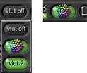
The Relative Path control, to the left of the Add to Favorites control in the File Browser, gives you the option to enter a relative file path into the File Name field.
Enable local file paths.
Disable local file paths.
Relative file paths can take one of two forms:
•./myDirectory/myFile/
•../myDirectory/myFile/
Directories Saved to the Favorites List Are Permanent
If there are one or more directories with content you frequently need to access, you can add them to the Favorites list. The Favorites list is a customizable list of directories that you can add to at any time. As of Shake 4, entries you add to the Favorites list are permanent.
Chapter 1 Shake 4.0 Interface Enhancements |
11 |
|
|
To add an entry to the favorites list: 1 Open the File Browser.
2 Click the Bookmark button.
The currently open directory is added to the Favorites list. All favorite directory paths you add are saved in the favoritePaths.h file, located in the $HOME/nreal/settings/ directory. To remove favorite directories, delete them from this file.
Locking Parameters
Most parameters now have a lock button next to the Autokey button. This control lets you lock that parameter so that it can’t be modified.
When you lock a parameter, its value field turns red to indicate that it’s locked.
Locked parameters cannot be edited, but if they contain keyframes, an expression, or a link to another parameter, these values continue to animate that parameter.
A Next Button to Create Additional Local Variables
When you create a local variable using the Local Variable Parameters window, you can click OK to create the variable and go back to your project, cancel to close the window without creating a new variable, or next to continue creating new variables.
The Console Tab
The Console tab displays the data that Shake sends to the OS while in operation. It’s a display-only tab. Two controls at the top of the Console tab let you change the color of the text, and erase the current contents of the Console. The maximum width of displayed text can be set via the consoleLineLength parameter, in the guiControls subtree of the Globals tab.
12 |
Chapter 1 Shake 4.0 Interface Enhancements |
|
|
New Global Parameters
The following new parameters have been added to the Globals tab:
consoleLineLength
The maximum line length of information displayed in the Console tab. This defaults to 120 characters.
textureProxy
The proxy level at which texture-rendered images that are used by the MultiPlane node’s hardware-rendering mode are displayed in the Viewer. This is similar to the interactiveScale setting, in that the proxy level that’s set here is used to generate on- the-fly Viewer images.
multiPlaneLocatorScale
Affects all MultiPlane nodes within the script. This parameter scales the depth of the virtual space used to distribute the locator points that are displayed in the Viewer (which represent 3D-tracking data clouds that are imported from .ma files). This parameter allows you to expand or compress the relative distance from the camera to the tracked background plate. Adjusting this parameter lets you more easily position layers in space when camera tracking data comes from a subject that’s either very far away, or very close. This parameter is for reference only, and has no effect on the data itself. The default multiPlaneLocatorScale value is 50.
noodleColor
Lets you change the base color of noodles in the Node View. Noodles are white by default, but you can use the Color control to change this to anything you like.
noodleColorA, -BW, -BWA, -RGB, -RGBA, -Z, -AZ, -BWZ, -BWAZ, -RGBZ, -RGBAZ
When noodleColorCoding is turned on (in the enhancedNodeView subtree), noodles are color coded and stippled (see “Noodle Color Coding” on page 16), based on the bit depth and number of color channels being propagated by each noodle in your node tree. When turned off, noodles appear using the default NoodleColor.
Different combinations of color channels are represented by different colors, and this group of parameters lets you customize the color used for each representation.
Using the Enhanced Node View
The enhancedNodeView subtree in the Globals tab provides additional display options for the Node View. These options can be turned on all together, or individually, to make it easy to spot image bit-depth at different parts of the tree, animated nodes, node concatenation, and expressions linking one node to another.
Chapter 1 Shake 4.0 Interface Enhancements |
13 |
|
|
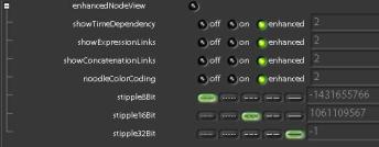
Unlike most other guiControls parameters, which are either off or on, these parameters—showTimeDependency, showExpressionLinks, showConcatentationLinks, and noodleColorCoding—have three states. This allows you to toggle all three parameters using the enhancedNodeView command from within the Node View. The three states are:
•off: Always off, regardless of whether or not enhancedNodeView is turned on.
•on: Always on, regardless of whether or not enhancedNodeView is turned on.
•enhanced: On when enhancedNodeView is on, and off when enhancedNodeView is off.
To toggle enhanced node view off and on:
1Before turning on enhanced Node View, make sure the proper subparameters are turned on in the enhancedNodeView subtree of the Globals tab.
2Move the pointer over the Node View, and do one of the following:
•Right-click, then choose Enhanced Node View from the shortcut menu.
•Press Control-E.
•Open the Globals tab, then click enhancedNodeView.
14 |
Chapter 1 Shake 4.0 Interface Enhancements |
|
|
Enhanced Node View Parameters
There are seven parameters in the enhancedNodeView subtree.
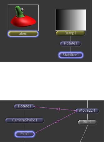
showTimeDependency
This parameter, when turned on, draws a bluish glow around nodes that are animated. This includes nodes that consist of FileIn nodes that reference a QuickTime movie or multiple-image sequence, nodes containing keyframed parameters, or nodes utilizing expressions that change a parameter’s value over time. In the following screenshot, the alien FileIn node is highlighted because it is a multi-frame animation. The Stabilize1 node is highlighted because it contains motion-tracking keyframes. The Ramp1 node is not highlighted because it’s only a single image, and the Rotate1 node is not animated.
showExpressionLinks
Turning this parameter on draws a light purple line connecting nodes that use expressions to reference other nodes. An arrow pointing from the linked node toward the referenced node indicates their relationship. In the following screenshot, the Move2D1 node contains expressions that link it to both the Rotate1 and Pan1 nodes.
Note: When you clone a node by copying it and then pasting it with the Paste Linked command, the resulting cloned node displays an expression link arrow when showExpressionLinks is turned on.
Chapter 1 Shake 4.0 Interface Enhancements |
15 |
|
|

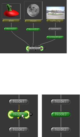
ShowConcatenationLinks
When this parameter is turned on, a green line connects a series of nodes that concatenate. For example, three transform nodes that have been added to a node tree in sequence so that they concatenate appear linked with a green line connecting the left edge of each node. As a result, nodes that break concatenation are instantly noticeable. In the following screenshot, the Rotate1, CameraShake1, and Pan1 nodes are concatenated.
Note: As is often repeated, node concatenation is a very good thing to take advantage of. You are encouraged to group nodes that concatenater whenever possible to improve the performance and visual quality of your output.
Noodle Color Coding
Turning on Shake’s noodle color coding parameters provides an additional way to visually distinguish the bit depth and channel information of the image data flowing down your node tree. With color coding turned on, you can see where in the node tree the bit depth is promoted or reduced, which noodles contain RGBA channel data versus BW data, and so forth.
Note: The Node View redraw speed of extremely large scripts may be reduced with noodleColorCoding turned on.
There are two kinds of coding used to identify the image data that noodles represent.
16 |
Chapter 1 Shake 4.0 Interface Enhancements |
|
|
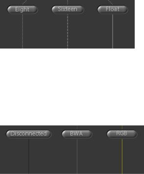
stipple8Bit, stipple16Bit, stipple32Bit
The stipple pattern of a noodle indicates its bit depth. In the following screenshot, three renamed Bytes nodes output 8-, 16-, and 32-bit float data respectively. The stippling indicates each bit depth at a glance.
noodleColor Coding
Different combinations of color channels being propagated down the node tree are represented by different colors. In the following screenshot (showing four renamed Reorder nodes), the first node is disconnected from any incoming image data, while the next two are respectively propagating BWA and RGB channels. The color channels represented by each noodle are clearly distinguishable (this screenshot is viewable in color via the onscreen help).
Customizing Noodle Color Coding
In the noodleColors subtree of the colors subtree, there are 12 different parameters for noodle color coding, corresponding to each possible combination of color channels in Shake. Each combination has a color control you can use to set up whichever color scheme makes the most sense to you.
Chapter 1 Shake 4.0 Interface Enhancements |
17 |
|
|

The top parameter, noodleColor, lets you change the base color of noodles in the Node View. Noodles are white by default, but you can use the color control to change this to anything you like.
Customizing Noodle Stippling
You can customize the stipple patterns of noodles in the enhancedNodeView subtree of the Globals tab. You can also customize the colors used to identify noodle bit depth in the noodleColors subtree of the colors subtree of the Globals tab.
18 |
Chapter 1 Shake 4.0 Interface Enhancements |
|
|
In the enhancedNodeView subtree, the stipple8Bit, stipple16Bit, and stipple32Bit parameters each have five different stipple patterns you can choose from, for maximum clarity.
Creating Custom Stipple Patterns
Different stipple patterns can be set in a .h preference file. Each stipple pattern is defined by a four-byte hex number that, when converted to binary, provides the pattern of the line drawn for each bit depth—each 1 corresponds to a dot, and each 0 corresponds to blank space.
For example, 0xFFFFFFFF is the hex equivalent of 1111111111, which creates a solid line. 0xF0F0F0 is the hex equivalent of 1111000011110000, which creates a dashed line.
The default settings are:
gui.nodeView.stipple8Bit = 0x33333333; gui.nodeView.stipple16Bit = 0x0FFF0FFF; gui.nodeView.stipple32Bit = 0xFFFFFFFF;
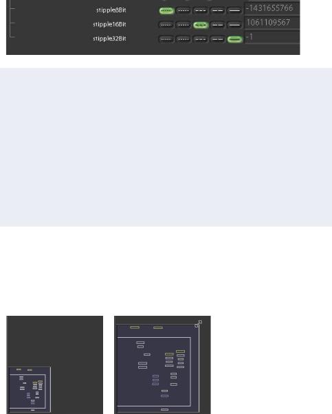
Resizing the Node Overview
The overview can be resized, making it easier to see.
To resize the node overview:
m Drag the upper-right corner, the top, or the right of the overview.
Default size |
After resizing |
Chapter 1 Shake 4.0 Interface Enhancements |
19 |
|
|
New Ways of Adding and Connecting Nodes
There are several new ways of working in the Node View.
To add one type of node to multiple nodes in the Node View: 1 Select two or more nodes in the Node View.
2In the Tool tabs, right-click the node you want to add, then choose Insert Multiple from the shortcut menu.
The new node is inserted after each selected node.
To connect one node to another by Shift-clicking: 1 Select the first node you want to connect.
20 |
Chapter 1 Shake 4.0 Interface Enhancements |
|
|
2Move the pointer over the second node you want to connect so that the knot is visible, then Shift-click the knot to connect both nodes together.
You can also use this technique to connect a group of nodes to a single multi-input node, such as the MultiLayer, MultiPlane, or Select node.
To connect several nodes to a multi-input node at once:
1 Select all of the nodes you want to connect to the multi-input node.
Chapter 1 Shake 4.0 Interface Enhancements |
21 |
|
|
2 Shift-click the plus sign input of the multi-input node.
All selected nodes are connected.
To insert a disconnected node between two existing nodes:
1Drag a node directly over a noodle so that both its knots appear highlighted. You can select which input of a multi-input node to insert by dragging the node to the left or right, so that the desired input knot is highlighted.
2 When you release the mouse button, the node is automatically inserted.
22 |
Chapter 1 Shake 4.0 Interface Enhancements |
|
|

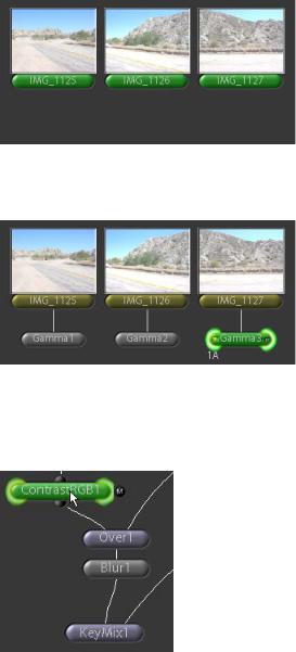
Cloned Node Naming
Cloned nodes are automatically named OriginalNode_CloneN, where N is the number of clones that have been made. You can clone a node as many times as you want, and all cloned nodes are linked to the original node. In the following screenshot, the Gamma1 node has been cloned twice, in order to apply an identical gamma correction to the other two images in the tree.
The links between cloned nodes can be viewed by turning on ShowExpressionLInks in the enhancedNodeView subtree of the Parameters tab. (and then turning on enhancedNodeView).
Monitor Calibration With Truelight
Shake includes Truelight, a color management system that lets you simulate on your Shake preview monitor, as closely as possible, the image that will eventually be printed to film or displayed on a high definition monitor or projector. This simulation is based on calibration data acquired from a variety of film stocks, film recorders, monitors, digital projectors, and film projectors, and on calibration profiles that you can generate yourself.
There are three parts to the Truelight tools:
•TLCalibrate, in the Other tab, is a utility node that you can use to accurately calibrate your monitor’s color characteristics. This node allows you to create a calibration profile by eyeballing adjustments to a series of ten images using the controls within this node. Once you’ve made your adjustments, you can save this profile for future use.
Note: This node also allows you to use calibration profiles generated by a Truelight Monitor probe.
Chapter 1 Shake 4.0 Interface Enhancements |
23 |
|
|
•The calibration profiles generated using TLCalibrate can then be used by the Truelight VLUT (Viewer lookup table) control in the Viewer shelf.
The Truelight VLUT lets you previsualize the image in the Viewer as it will look after being output from a film recorder, or displayed by a high definition monitor or projector. You can use the Load Viewer Lookup command to make adjustments to the Truelight VLUT parameters in the Parameters tab, choosing which device profile you want to emulate.
•A second node in the Color tab, Truelight, performs the same function as the Truelight VLUT, except that it can be added to the node tree. The Truelight node has parameters that are identical to the Truelight VLUT that let you specify the device profile, current display profile, and color space for the preview. Additional controls let you fine-tune the preview.
Important: The Truelight functions are intended for previsualization only. They are not intended for use as color correction operations.
For more information on using the Truelight plugins, see the Truelight documentation, located in the Documentation folder on the Shake installation disk.
Updated Onscreen Controls for Transform Nodes
The pan, scale, and rotate onscreen controls have been updated, and have additional keyboard shortcuts for transforming an image without having to position the pointer directly over it.
24 |
Chapter 1 Shake 4.0 Interface Enhancements |
|
|
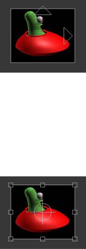
Pan
The pan controls provide two ways to move the image within the Viewer. Drag anywhere within the image bounding box to reposition the image freely. Drag the vertical arrowhead to restrict position changes to the yPan parameter. Drag the horizontal arrowhead to restrict position changes to the xPan parameter.
You can also press Q or P while dragging anywhere within the Viewer to pan an image without having to position the pointer directly over it.
Scale
Drag any of the corner controls to scale the entire image up or down, affecting the xScale and yScale parameters. Drag the top or bottom controls to scale the image vertically, affecting only the yScale parameter. Drag the left or right controls to scale the image horizontally, affecting only the xScale parameter.
Drag the center control to move the point about which scaling is performed, affecting the xCenter and yCenter parameters.
There is an additional method you can use to scale images in the Viewer.
To scale an image in the Viewer without using the scale handles: 1 Select an image.
2 With the pointer positioned over the Viewer, press E or I.
Chapter 1 Shake 4.0 Interface Enhancements |
25 |
|
|
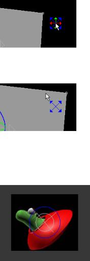
3When the dimension pointer appears, drag in the direction you want to scale the image. The colors in the dimension pointer correspond to the pan controls.
When you drag, the dimension pointer turns into an axis arrow, indicating the dimension in which you are scaling the image -- horizontal, vertical or diagonal.
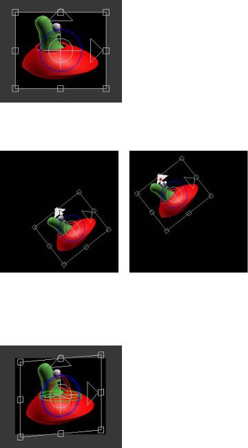
Rotate
Drag the blue rotate control to rotate the image about the center point, affecting the angle parameter. Drag the white center control to move the center point itself, affecting the xCenter and yCenter parameters.
To rotate an image without positioning the pointer directly over it, press W or O, then drag in the Viewer. The dimension pointer appears, allowing you to to rotate the image in any direction.
26 |
Chapter 1 Shake 4.0 Interface Enhancements |
|
|
Move2D
The Move2D node combines the onscreen transform controls for the Pan, Scale, and Rotate nodes into a single, all-purpose transformation node.
After an image is rotated with the Move2D node, the horizontal and vertical panning controls (arrowheads) lock movement to the new orientation of the image.
Move3D
Similar to the Move2D node, the Move3D node adds three colored dimensional angle controls to control xAngle (red), yAngle (green), and zAngle (blue) parameters. This lets you simulate 3D transformations with 2D images.
Chapter 1 Shake 4.0 Interface Enhancements |
27 |
|
|
As with the Move2D node, when an image is panned with the Move3D node, the horizontal and vertical panning controls lock movement to the new orientation of the image, instead of the absolute orientation of the Viewer frame.
There are keyboard shortcuts (identical to those used within the MultiPlane node) that you can use to manipulate images without having to position the pointer directly over them.
Note: Unlike similar controls available for layers connected to the MultiPlane node, the constrained pan controls do not move the image forward or back if the yAngle is tilted. To manipulate images within a more fully featured 3D environment, connect them to a MultiPlane node, and use the available controls.
28 |
Chapter 1 Shake 4.0 Interface Enhancements |
|
|

Major Features and New Nodes |
2 |
This chapter covers major new features, and new nodes that have been added to Shake 4.
Support For the OpenEXR Format
OpenEXR (.exr) is an extremely flexible, cross-platform file format developed and maintained by Industrial Light & Magic. Key features of the OpenEXR format include support for the efficient storage of high dynamic-range image data using the 16-bit float “half” format, and support for auxiliary image data channels. OpenEXR 16-bit float and 32-bit float data channels can be read directly into Shake’s RGBAZ data channels. In addition, OpenEXR 32-bit unsigned integer channel data can be read into Shake’s Z data channel, although Shake’s image processing nodes cannot process this data.
Note: 32-bit unsigned integer channel data will only be useful to custom plug-ins with built-in logic capable of processing the data within the Z channel.
A major feature of the OpenEXR format is its ability to support an extremely wide dynamic range. Thanks to its floating-point support, a contrast range of up to 30 f-stops can be supported with no loss of precision. Color resolution in 16-bit float (“half”) files is 1024 steps per f-stop.
Another advantage of the OpenEXR format is support for any number of additional auxillary data channels, in addition to the standard RGBAZ channels. For example, additional channels can be written to store luminance, surface normal direction channels, velocity channels, and even individual lighting passes written from a 3D rendering application.
29
Shake Support for Auxiliary OpenEXR Data Channels
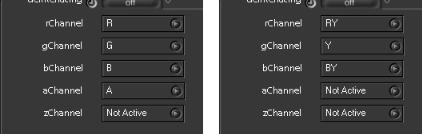
Internally, Shake only supports the processing of RGBAZ channels down the processing tree. However, the FileIn node provides channel remapping options in the Image tab of a FileIn node’s parameters. Each channel that Shake supports has a corresponding popup menu. Each menu presents a list of every compatible channel within the referenced OpenEXR file. Color channels that correspond to Shake’s supported channels are mapped by default.
FileIn channel pop-up menus for two files with different image channels
To remap any image channel:
1 Load a FileIn node that references an OpenEXR file into the Preferences tab.
2Choose a new channel to map to from any color channel pop-up menu. Channel remapping has the following restrictions:
•Any 16-bit or 32-bit float channel can be remapped within the RGBAZ channels.
•32-bit integer channels can only be remapped to the Z channel.
Note: If you want to access multiple 32-bit integer channels within a script, duplicate a number of FileIn nodes equal to the number of channels you want to access, then remap each 32-bit integer channel to a Z channel of one of the duplicate FileIn nodes.
Support for Data Compression
The OpenEXR format supports several codecs, with options for either lossless or lossy compression. Compression ratios range from 2:1 to 3:1.
Note: By default, FileOut nodes set to output OpenEXR images default to the Piz codec.
The following codec information appears courtesy of Industrial Light & Magic:
•none: No compression is applied.
•RLE: (Lossless) Differences between horizontally adjacent pixels are run-length encoded. This method is fast, and works well for images with large flat areas. But for photographic images, the compressed file size is usually between 60 and 75 percent of the uncompressed size.
30 |
Chapter 2 Major Features and New Nodes |
|
|
Loading...