


 Loading...
Truelight
Version 2.1
Shake Node
FilmLight
D I G I T A L F I L M T E C H N O L O G Y
Truelight
Product Version: 2.1
Shake Node
Document Version: 1.2
Date: 17/03/2005
Modified: 14/04/2005 21:03
© FilmLight 2005
Truelight
Truelight Overview |
|
1 |
|
Shake Node |
|
Truelight Overview
Truelight is a complete film colour management system for pre-visualising film images on electronic display devices. It provides a full simulation of the entire workflow from digital data to final projected image. By carefully measuring and characterising each stage in the workflow, the closest possible match between preview on the Shake monitor and the final projected film image can be achieved.
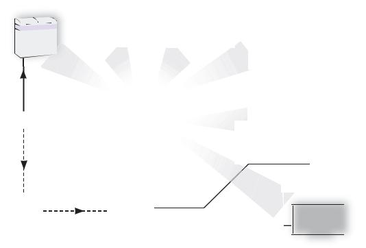
The simplified overview diagram below shows how the Truelight system uses calibration data to create a 3D colour-cube transform, accurately matching the electronic display of digital film images to the projection of a print created from the same digital source:
FILM RECORDER |
NEG FILM |
PRINT FILM |
|
|
|
||||||||||||||||
|
|
|
|
STOCK |
|
|
STOCK |
|
FILM PROJECTOR |
||||||||||||
|
|
|
|
|
|
|
|
|
|
|
|
|
|
|
|
|
|
|
|
||
|
|
|
|
|
|
|
|
|
|
|
|
|
|
|
|
|
|
|
|
|
|
|
|
|
|
|
|
|
|
|
|
|
|
|
|
|
|
|
|
|
|
|
|
|
|
|
|
|
CAL |
|
|
|
|
|
|
|
|
|
|
|
|
|
|
|
|
|
|
|
|
|
|
CAL |
|
|
|
|
|
|
|
|
|
|
|||||
|
|
|
|
|
|
|
|
|
|
|
|||||||||||
|
|
CAL |
|
|
|
|
|
|
|
|
|
|
|
|
|
|
|
|
CAL |
|
|
|
|
|
|
|
|
|
|
|
|
|
|
|
|
|
|
|
|
|
|
|
|
|
|
|
|
|
|
|
|
|
|
|
|
|
|
|
|
|
|
|
|
|
|
|
|
|
|
|
|
|
|
|
|
|
|
|
|
|
|
|
|
|
|
|
|
|
|
|
|
|
|
|
|
|
|
|
|
|
|
|
|
|
|
|
|
|
|
|
|
|
|
|
|
|
|
|
|
|
|
|
|
|
|
|
|
|
|
|
|
|
|
|
|
|
|
|
|
|
|
|
|
|
|
|
|
|
|
|
|
|
|
|
COMBINED |
|
||||||||
|
CALIBRATION |
|
||||||||
|
|
|
|
|
||||||
DIGITAL FILM |
|
|
CAL |
|
|
|
HD MONITOR OR |
|||
IMAGES |
|
|
|
|
|
|
|
DIGITAL PROJECTOR |
||
|
|
|
|
|
|
|
|
|
|
|
|
|
|
|
|
|
|
|
|
|
|
|
|
|
|
|
|
|
|
|
|
|
SHAKE |
TRUELIGHT TRANSFORM |
|
||
(PLUGIN) |
|
|||
|
UI MONITOR |
|||
|
|
|
CAL |
|
|
|
|
|
|
|
|
|
|
|
|
|
|
|
|
For more details on Truelight, please visit the FilmLight web pages at www.filmlight.ltd.uk, and follow the product link to the Truelight sections.
Truelight

2Truelight Licence
Shake Node
Truelight Licence
Truelight is automatically licensed to use generic profiles. The Truelight node can be upgraded to load custom profiles if required.
For further information, please refer to the Truelight support section of the FilmLight website:
www.filmlight.ltd.uk/support/truelight.html
Truelight
Monitor Calibration |
|
3 |
|
Shake Node |
|
Monitor Calibration
A monitor must be correctly calibrated before it can accurately reproduce images. The Truelight node provides a built in tool for the visual calibration of the Shake monitor. It is also possible to use monitor calibration files which have been created using a Truelight Monitor Probe and imported into the machine.
Before calibrating the Shake monitor, it should be set up to ensure optimal performance in your current viewing environment. You should use the controls on the display to set the brightness, the contrast, and the white point. The FilmLight recommended practice document RP-FL001 “Viewing Environment and Monitor Setup” gives more detailed advice on setting up your viewing environment - this can be downloaded from the FilmLight website.
The following procedure applies to the visual calibration of the Shake user interface monitor. If you have an external HD broadcast monitor, Truelight provides two preset calibration options which may be appropriate for your monitor (see step 5 on page 8).
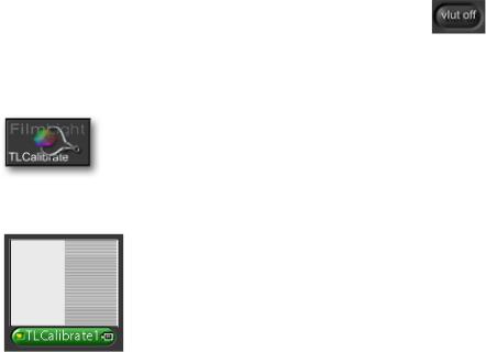
 Before starting, ensure that the VLUT and user scripts are switched off:
To start the Truelight Monitor Calibration utility:
1Click on the ‘other’ tool tab
2This tab should include two Truelight icons - click on the Truelight Calibrate icon:
ÎA ‘TLCalibrate’ node will appear in the Node View. This node does not require any inputs or outputs as it is just being used to generate a series of lineup patterns in the viewer:
Truelight

4Monitor Calibration
Shake Node
3The viewer should currently be displaying two patches side-by-side, a mid grey patch on the left and a patch composed of alternate white and black lines on the right. Select the Parameters1 tab to access the Truelight monitor calibration controls:
Before adjusting any of the controls, check that the ‘useProxy’ setting in the ‘Globals’ parameter tab is set to ‘Base’, and the viewer is set to a 1:1 zoom. If necessary, click on the viewer Home button  to reset the viewer.
4Leave the gang button turned on so that all three sliders move together and then drag any of the rgb sliders to the left or right, to visually match the ‘brightness’ of the two halves of the screen.
ÎIt may help to view the screen through half-closed eyes so that the white/black lines on the right-hand side of the viewer appear to merge into a continuous grey patch.
5If there is any noticeable colour cast on the left side of the screen compared to the right, click on the gang button to turn it off and then trim the rgb sliders independently to match the colour of the two patches.
6Once the two halves of the viewer match, and there appears to be a single uniform grey patch across the whole monitor, click on the ‘Next’ step button
ÎTwo new patches appear at half the level of the previous ones (i.e. one stop less), and the step number shown above the rgb sliders increments.
Truelight
Loading...