


ACS800
Hardware Manual
ACS800-PC Drives (150 to 600 HP)

2
ACS800 Single Drive Manuals
HARDWARE MANUALS
(appropriate manual is included in the delivery)
ACS800-04/U4 Hardware Manual 90 to 500 kW (125 to 600 HP) 3AFE64671006 (English)
•Safety instructions
•Electrical installation planning
•Mechanical and electrical installation
•Motor control and I/O board (RMIO)
•Maintenance
•Technical data
•Dimensional drawings
•Resistor braking
FIRMWARE MANUALS, SUPPLEMENTS AND GUIDES
(appropriate documents are included in the delivery)
Standard Application Program Firmware Manual 3AFE64527592 (English)
System Application Program Firmware Manual 3AFE63700177 (English)
Application Program Template Firmware Manual 3AFE64616340 (English)
Master/Follower 3AFE64590430 (English)
PFC Application Program Firmware Manual 3AFE64649337 (English)
Extruder Control Program Supplement 3AFE64648543 (English)
Centrifuge Control Program Supplement 3AFE64667246 (English)
Traverse Control Program Supplement 3AFE64618334 (English)
Crane Control Program Firmware Manual 3BSE11179 (English)
Adaptive Programming Application Guide 3AFE64527274 (English)
OPTION MANUALS
(delivered with optional equipment)
Fieldbus Adapters, I/O Extension Modules etc.
ACS800-PC Drives
150 to 600 HP
Hardware Manual
3AUA0000010601 Rev. C
EFFECTIVE: 10/16/2009
2009 ABB Inc. All Rights Reserved.
5
Safety Instructions
What this Chapter Contains
This chapter contains the safety instructions which you must follow when installing, operating and servicing the drive. If ignored, physical injury or death may follow, or damage may occur to the drive, the motor or driven equipment. Read the safety instructions before you work on the unit.
Use of Warnings and Notes
There are two types of safety instructions throughout this manual: warnings and notes. Warnings caution you about conditions which can result in serious injury or death and/or damage to the equipment. They also tell you how to avoid the danger. Notes draw attention to a particular condition or fact, or give information on a subject. The warning symbols are used as follows:
Dangerous voltage warning warns of high voltage which can cause physical injury and/or damage to the equipment.
General warning warns about conditions, other than those caused by electricity, which can result in physical injury and/or damage to the equipment.
Electrostatic discharge warning warns of electrostatic discharge which can damage the equipment.
Special note or recommendation. This symbol is used to highlight especially important information or recommendation for product application.
Safety Instructions

6
Installation and Maintenance Work
These warnings are intended for all who work on the drive, motor cable or motor. Ignoring the instructions can cause physical injury or death.
WARNING!
•Only qualified electricians are allowed to install and maintain the drive.
•Never work on the drive, motor cable or motor when main power is applied. After switching off the power, always wait for 5 minutes to let the intermediate circuit capacitors discharge before you start working on the drive, the motor or the motor cable.
Always ensure by measuring with a multimeter (impedance at least 1 Mohm) that:
1.Voltage between drive input phases L1, L2 and L3 and the frame is close to 0 V.
2.Voltage between terminals UDC+ and UDCand the frame is close to 0 V.
•Do not work on the control cables when power is applied to the drive or to the external control circuits. Externally supplied control circuits may cause dangerous voltages inside the drive even when the main power on the drive is switched off.
•Do not make any insulation or voltage withstand tests on the drive or drive modules.
•When reconnecting the motor cable, always check that the phase order is correct.
Note:
•The disconnecting device (means) of the drive does not isolate the input cables and busbars from the main AC supply. Before working inside the cabinet, isolate the input cables and busbars from the main supply with the disconnecting device at the distribution board or with the disconnector of the supply transformer.
•The motor cable terminals on the drive are at a dangerously high voltage when the input power is on, regardless of whether the motor is running or not.
•The brake control terminals (UDC+, UDC-, R+ and R- terminals) carry a dangerous DC voltage (over 500 V).
•Depending on the external wiring, dangerous voltages [115 V, 220 V or 230 V] may be present on the terminals of relay outputs RO1 to RO3.
•The Prevention of Unexpected Start function does not remove the voltage from the main and auxiliary circuits.
Safety Instructions

7
WARNING!
•Cover the drive when installing to ensure that dust from drilling or foreign objects do not enter the drive. Electrically conductive dust inside the unit may cause damage or lead to malfunction.
•Ensure sufficient cooling.
•Welding of the cabinet frame is not recommended. However, if electric welding is the only way to mount the cabinet, follow the instructions given in chapter "Mechanical Installation". Ensure that welding fumes are not inhaled. If the welding return wire is connected improperly, the welding circuit may damage electronic circuits in the cabinet.
•When removing the module from the cabinet and manoeuvring it outside the cabinet, prevent it from toppling over by securing it. The drive module is heavy and has a high center of gravity.
WARNING! The printed circuit boards contain components sensitive to electrostatic discharge. Wear a grounding wrist band when handling the boards. Do not touch the boards unnecessarily.
Safety Instructions

8
Grounding
These instructions are intended for all who are responsible for the grounding of the drive. Incorrect grounding can cause physical injury, death or equipment malfunction and increase electromagnetic interference.
WARNING!
•Ground the drive, the motor and adjoining equipment to ensure personnel safety in all circumstances, and to reduce electromagnetic emission and pickup.
•Make sure that grounding conductors are adequately sized as required by safety regulations.
•In a multiple-drive installation, connect each drive separately to protective earth (PE).
•Do not install a drive with EMC filter option +E202 on an ungrounded power system or a high resistance-grounded (over 30 ohms) power system.
Note:
•Power cable shields are suitable for equipment grounding conductors only when adequately sized to meet safety regulations.
•As the normal leakage current of the drive is higher than 3.5 mA AC or 10 mA DC (stated by EN 50178, 5.2.11.1), a fixed protective earth connection is required.
Fiber Optic Cables
WARNING! Handle the fibre optic cables with care. When unplugging optic cables, always grab the connector, not the cable itself. Do not touch the ends of the fibres with bare hands as the fibre is extremely sensitive to dirt. The minimum allowed bend radius is 35 mm (1.4 in.).
Safety Instructions

9
Operation
These warnings are intended for all who plan the operation of the drive or operate the drive. Ignoring the instructions can cause physical injury or death or damage the equipment.
WARNING!
•Before adjusting the drive and putting it into service, make sure that the motor
and all driven equipment are suitable for operation throughout the speed range provided by the drive. The drive can be adjusted to operate the motor at speeds above and below the speed provided by connecting the motor directly to the power line.
•Do not activate automatic fault reset functions of the Standard Application Program if dangerous situations can occur. When activated, these functions will reset the drive and resume operation after a fault.
•Do not control the motor with the disconnecting device (disconnecting means); instead, use the control panel keys 
 and
and 
 , or commands via the I/O board of the drive. The maximum allowed number of charging cycles of the DC capacitors (i.e. power-ups by applying power) is five in ten minutes.
•Do not use the optional Prevention of Unexpected Start function for stopping the drive when the drive is running. Give a Stop command instead.
Note:
•If an external source for start command is selected and it is ON, the drive (with Standard Application Program) will start immediately after fault reset unless the drive is configured for 3-wire (a pulse) start/stop.
•When the control location is not set to Local (L not shown in the status row of the display), the stop key on the control panel will not stop the drive. To stop
the drive using the control panel, press the LOC/REM key and then the stop key  .
.
Safety Instructions

10
Permanent Magnet Motor
These are additional warnings concerning permanent magnet motor drives.
WARNING! Do not work on the drive when the permanent magnet motor is rotating. Also, when the supply power is switched off and the inverter is stopped, a rotating permanent magnet motor feeds power to the intermediate circuit of the drive and the supply connections become live.
Installation and Maintenance Work
Before installation and maintenance work on the drive:
•Disconnect the motor from the drive with a safety switch and additionally if possible (or)
•lock the motor shaft and ground the motor connection terminals temporarily by connecting them together as well as to the PE. Before grounding, measure that the motor is de-energized.
Operation
Do not run the motor over the rated speed. Motor overspeed leads to overvoltage which may explode the capacitors in the intermediate circuit of the drive.
Safety Instructions
11
Table of Contents
Safety Instructions
What this Chapter Contains . . . . . . . . . . . . . . . . . . . . . . . . . . . . . . . . . . . . . . . . 5
Use of Warnings and Notes . . . . . . . . . . . . . . . . . . . . . . . . . . . . . . . . . . . . . . . . 5
Installation and Maintenance Work . . . . . . . . . . . . . . . . . . . . . . . . . . . . . . . . . . 6
Operation . . . . . . . . . . . . . . . . . . . . . . . . . . . . . . . . . . . . . . . . . . . . . . . . . . . . . . 9
Permanent Magnet Motor . . . . . . . . . . . . . . . . . . . . . . . . . . . . . . . . . . . . . . . . . 10
Table of Contents
About this Manual
What this Chapter Contains . . . . . . . . . . . . . . . . . . . . . . . . . . . . . . . . . . . . . . . 14 Target Audience . . . . . . . . . . . . . . . . . . . . . . . . . . . . . . . . . . . . . . . . . . . . . . . . 14 Common Chapters for Products . . . . . . . . . . . . . . . . . . . . . . . . . . . . . . . . . . . . 14 Categorization According to the Frame Size . . . . . . . . . . . . . . . . . . . . . . . . . . 14 Categorization According to the + Code . . . . . . . . . . . . . . . . . . . . . . . . . . . . . 14 Contents . . . . . . . . . . . . . . . . . . . . . . . . . . . . . . . . . . . . . . . . . . . . . . . . . . . . . . 15 Installation and Commissioning Flowchart . . . . . . . . . . . . . . . . . . . . . . . . . . . . 16 Inquiries . . . . . . . . . . . . . . . . . . . . . . . . . . . . . . . . . . . . . . . . . . . . . . . . . . . . . . 17
The ACS800-PC
What this Chapter Contains . . . . . . . . . . . . . . . . . . . . . . . . . . . . . . . . . . . . . . . 18
The ACS800-PC . . . . . . . . . . . . . . . . . . . . . . . . . . . . . . . . . . . . . . . . . . . . . . . . 18
Type Code . . . . . . . . . . . . . . . . . . . . . . . . . . . . . . . . . . . . . . . . . . . . . . . . . . . . 19
Product Ordering — Special Note . . . . . . . . . . . . . . . . . . . . . . . . . . . . . . . . . . 20
Main Circuit and Control . . . . . . . . . . . . . . . . . . . . . . . . . . . . . . . . . . . . . . . . . . 20
Mechanical Installation
What this Chapter Contains . . . . . . . . . . . . . . . . . . . . . . . . . . . . . . . . . . . . . . . 23 Moving the Unit . . . . . . . . . . . . . . . . . . . . . . . . . . . . . . . . . . . . . . . . . . . . . . . . 23 Before Installation . . . . . . . . . . . . . . . . . . . . . . . . . . . . . . . . . . . . . . . . . . . . . . . 24 Fastening the Cabinet to the Floor and Wall . . . . . . . . . . . . . . . . . . . . . . . . . . 26 Electric Welding . . . . . . . . . . . . . . . . . . . . . . . . . . . . . . . . . . . . . . . . . . . . . . . . 28
Planning the Electrical Installation
What this Chapter Contains . . . . . . . . . . . . . . . . . . . . . . . . . . . . . . . . . . . . . . . 29
To Which Products this Chapter Applies . . . . . . . . . . . . . . . . . . . . . . . . . . . . . 29
Motor Selection and Compatibility . . . . . . . . . . . . . . . . . . . . . . . . . . . . . . . . . . 29
Permanent Magnet Synchronous Motor . . . . . . . . . . . . . . . . . . . . . . . . . . . . . . 33
Supply Connection . . . . . . . . . . . . . . . . . . . . . . . . . . . . . . . . . . . . . . . . . . . . . . 33
Table of Contents

12
Thermal Overload and Short-Circuit Protection . . . . . . . . . . . . . . . . . . . . . . . . 34 Ground Fault Protection . . . . . . . . . . . . . . . . . . . . . . . . . . . . . . . . . . . . . . . . . . 34 Emergency Stop Devices . . . . . . . . . . . . . . . . . . . . . . . . . . . . . . . . . . . . . . . . . 35 Prevention of Unexpected Start (ACS800-07/U7 only) . . . . . . . . . . . . . . . . . . . 36 Selecting the Power Cables . . . . . . . . . . . . . . . . . . . . . . . . . . . . . . . . . . . . . . . 37 Power Factor Compensation Capacitors . . . . . . . . . . . . . . . . . . . . . . . . . . . . . . 39 Equipment Connected to the Motor Cable . . . . . . . . . . . . . . . . . . . . . . . . . . . . 40 Protecting the Relay Output Contacts and Attenuating
Disturbances in Case of Inductive Loads . . . . . . . . . . . . . . . . . . . . . . . . . . . . . 41 Selecting the Control Cables . . . . . . . . . . . . . . . . . . . . . . . . . . . . . . . . . . . . . . . 42 Connection of a Motor Temperature Sensor to the Drive I/O . . . . . . . . . . . . . . 43 Routing the Cables . . . . . . . . . . . . . . . . . . . . . . . . . . . . . . . . . . . . . . . . . . . . . . 43
Electrical Installation |
|
What this Chapter Contains . . . . . . . . . . . . . . . . . . . . . . . . . . . . . . . . . . . . . . . |
45 |
Before Installation . . . . . . . . . . . . . . . . . . . . . . . . . . . . . . . . . . . . . . . . . . . . . . . |
45 |
Checking the Insulation of the Assembly . . . . . . . . . . . . . . . . . . . . . . . . . . . . . |
46 |
Warning Sticker . . . . . . . . . . . . . . . . . . . . . . . . . . . . . . . . . . . . . . . . . . . . . . . . . |
46 |
Example Wiring Diagram . . . . . . . . . . . . . . . . . . . . . . . . . . . . . . . . . . . . . . . . . . |
47 |
Power Cable Connection Diagram . . . . . . . . . . . . . . . . . . . . . . . . . . . . . . . . . . |
48 |
Connecting the Power Cables . . . . . . . . . . . . . . . . . . . . . . . . . . . . . . . . . . . . . . |
49 |
Connecting the Control Cables . . . . . . . . . . . . . . . . . . . . . . . . . . . . . . . . . . . . . |
50 |
Installation of Optional Modules . . . . . . . . . . . . . . . . . . . . . . . . . . . . . . . . . . . . |
52 |
Layout Drawing of Factory Installed Optional Equipment . . . . . . . . . . . . . . . . . |
54 |
Motor Control and I/O Board (RMIO) |
|
What this Chapter Contains . . . . . . . . . . . . . . . . . . . . . . . . . . . . . . . . . . . . . . . |
55 |
To Which Products this Chapter Applies . . . . . . . . . . . . . . . . . . . . . . . . . . . . . . |
55 |
Note for the ACS800-02 with Enclosure Extension, ACS800-07/U7, and |
|
ACS800-PC . . . . . . . . . . . . . . . . . . . . . . . . . . . . . . . . . . . . . . . . . . . . . . . . . . . . |
55 |
Note on External Power Supply . . . . . . . . . . . . . . . . . . . . . . . . . . . . . . . . . . . . |
55 |
RMIO board specifications . . . . . . . . . . . . . . . . . . . . . . . . . . . . . . . . . . . . . . . . |
57 |
Installation Checklist and Start-Up
Checklist . . . . . . . . . . . . . . . . . . . . . . . . . . . . . . . . . . . . . . . . . . . . . . . . . . . . . . 60
Start-Up Procedure . . . . . . . . . . . . . . . . . . . . . . . . . . . . . . . . . . . . . . . . . . . . . . 61
Maintenance |
|
What this Chapter Contains . . . . . . . . . . . . . . . . . . . . . . . . . . . . . . . . . . . . . . . |
62 |
Safety . . . . . . . . . . . . . . . . . . . . . . . . . . . . . . . . . . . . . . . . . . . . . . . . . . . . . . . . |
62 |
Maintenance Intervals . . . . . . . . . . . . . . . . . . . . . . . . . . . . . . . . . . . . . . . . . . . . |
62 |
Air Filter Material . . . . . . . . . . . . . . . . . . . . . . . . . . . . . . . . . . . . . . . . . . . . . . . . |
62 |
Checking and Replacing the Air Filters . . . . . . . . . . . . . . . . . . . . . . . . . . . . . . . |
63 |
Exhaust Filter for UL Type 12 . . . . . . . . . . . . . . . . . . . . . . . . . . . . . . . . . . . . . . |
66 |
Heatsink . . . . . . . . . . . . . . . . . . . . . . . . . . . . . . . . . . . . . . . . . . . . . . . . . . . . . . |
68 |
Table of Contents

13
Fans . . . . . . . . . . . . . . . . . . . . . . . . . . . . . . . . . . . . . . . . . . . . . . . . . . . . . . . . . 68
Replacing the Cabinet Fan . . . . . . . . . . . . . . . . . . . . . . . . . . . . . . . . . . . . . . . . 69
Layout of the Drive Module . . . . . . . . . . . . . . . . . . . . . . . . . . . . . . . . . . . . . . . 72
Capacitors . . . . . . . . . . . . . . . . . . . . . . . . . . . . . . . . . . . . . . . . . . . . . . . . . . . . 75
Replacing the Drive Module . . . . . . . . . . . . . . . . . . . . . . . . . . . . . . . . . . . . . . . 77
LEDs . . . . . . . . . . . . . . . . . . . . . . . . . . . . . . . . . . . . . . . . . . . . . . . . . . . . . . . . . 80
Technical Data
What this Chapter Contains . . . . . . . . . . . . . . . . . . . . . . . . . . . . . . . . . . . . . . . 81
Free Space Around the Unit . . . . . . . . . . . . . . . . . . . . . . . . . . . . . . . . . . . . . . 87
Input Power Connection . . . . . . . . . . . . . . . . . . . . . . . . . . . . . . . . . . . . . . . . . . 88
Motor Connection . . . . . . . . . . . . . . . . . . . . . . . . . . . . . . . . . . . . . . . . . . . . . . . 88
Efficiency . . . . . . . . . . . . . . . . . . . . . . . . . . . . . . . . . . . . . . . . . . . . . . . . . . . . . 88
Cooling . . . . . . . . . . . . . . . . . . . . . . . . . . . . . . . . . . . . . . . . . . . . . . . . . . . . . . . 89
Degrees of Protection . . . . . . . . . . . . . . . . . . . . . . . . . . . . . . . . . . . . . . . . . . . . 89
Ambient Conditions . . . . . . . . . . . . . . . . . . . . . . . . . . . . . . . . . . . . . . . . . . . . . 89
Materials . . . . . . . . . . . . . . . . . . . . . . . . . . . . . . . . . . . . . . . . . . . . . . . . . . . . . . 90
Applicable Standards . . . . . . . . . . . . . . . . . . . . . . . . . . . . . . . . . . . . . . . . . . . . 90
CE Marking . . . . . . . . . . . . . . . . . . . . . . . . . . . . . . . . . . . . . . . . . . . . . . . . . . . . 91
Equipment Warranty and Liability . . . . . . . . . . . . . . . . . . . . . . . . . . . . . . . . . . . 92
Dimensional Drawings
Resistor Braking
What this Chapter Contains . . . . . . . . . . . . . . . . . . . . . . . . . . . . . . . . . . . . . . . 95 To Which Products this Chapter Applies . . . . . . . . . . . . . . . . . . . . . . . . . . . . . 95 Availability of Brake Choppers and Resistors for the ACS800 . . . . . . . . . . . . . 95 How to Select the Correct Drive/Chopper/Resistor Combination . . . . . . . . . . . 95 Optional Brake Chopper and Resistor(s) for the ACS800-U2, ACS800-U4, ACS800-PC and ACS800-07/U7 . . . . . . . . . . . . . . . . . . . . . . . . . . . . . . . . . . . 96 Resistor Installation and Wiring . . . . . . . . . . . . . . . . . . . . . . . . . . . . . . . . . . . . 96 Protection of Frame Sizes R7 and R8 (ACS800-U2, ACS800-U4,
ACS800-PC, ACS800-U7/07) . . . . . . . . . . . . . . . . . . . . . . . . . . . . . . . . . . . . . 97 Brake Circuit Commissioning . . . . . . . . . . . . . . . . . . . . . . . . . . . . . . . . . . . . . . 98
Table of Contents

14
About this Manual
What this Chapter Contains
This chapter describes the intended audience and contents of the manual. It contains a flowchart of steps in checking the delivery, installing and commissioning the drive. The flowchart refers to chapters/sections in this manual and other manuals.
Target Audience
This manual is intended for people who plan the installation, install, commission, use and service the drive. Read the manual before working on the drive. The reader is expected to know the fundamentals of electricity, wiring, electrical components and electrical schematic symbols.
The manual is written for readers worldwide. Both SI and imperial units are shown. Special US instructions for installations within the United States that must be performed per the National Electrical Code and local codes are marked with (US).
Common Chapters for Products
Chapters "Planning the Electrical Installation", "Motor Control and I/O Board (RMIO)" and "Resistor Braking" apply to the ACS800-01/U1, ACS800-02/U2, ACS800-04/U4, ACS800-07/U7, and ASC800-PC.
Categorization According to the Frame Size
Some instructions, technical data and dimensional drawings which concern only certain frame sizes are marked with the symbol of the frame size R2, R3... or R8. The frame size is not marked on the drive designation label. To identify the frame size of your drive, see the rating tables in chapter "Technical Data".
Categorization According to the + Code
The instructions, technical data and dimensional drawings which concern only certain optional selections are marked with + codes, e.g. +E205. The options included in the drive can be identified from the + codes visible on the type designation label of the drive. The + code selections are listed in chapter "The ACS800-PC" under "Type Code".
About this Manual

15
Contents
The chapters of this manual are briefly described below.
"Safety Instructions" give safety instructions for the installation, commissioning, operation and maintenance of the drive.
"About this Manual" introduces this manual. "The ACS800-PC" describes the drive.
"Mechanical Installation" shows how to move and unpack the delivery and how to fasten the cabinet to the floor.
"Planning the Electrical Installation" instructs on the motor and cable selection, the protections and the cable routing.
"Electrical Installation" instructs how to wire the drive.
"Motor Control and I/O Board (RMIO)" shows external control connections to the motor control and I/O board and its specifications.
"Installation Checklist and Start-Up" helps in checking the mechanical and electrical installation of the drive.
"Maintenance" contains preventive maintenance instructions.
"Technical Data" contains the technical specifications of the drive, e.g. the ratings, sizes and technical requirements, provisions for fulfilling the requirements for CE and other markings and warranty policy.
"Dimensional Drawings" contains the dimensional drawings of the drive.
"Resistor Braking" describes how to select, protect and wire optional brake choppers and resistors. The chapter also contains technical data.
About this Manual
16
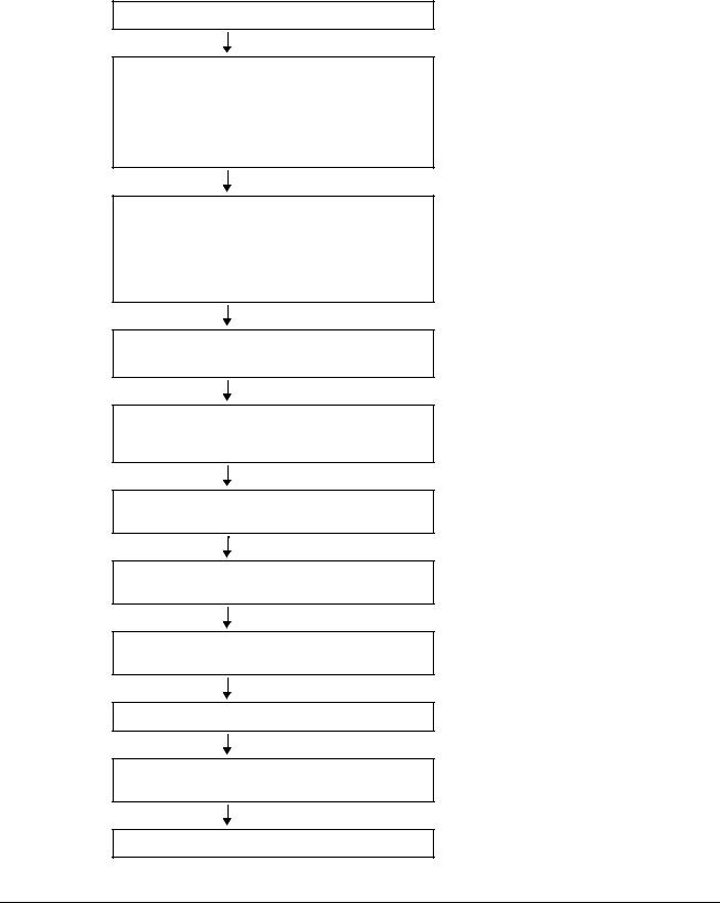
Installation and Commissioning Flowchart
Task
Identify the frame size of your drive: R7 or R8.
Plan the installation.
Check the ambient conditions, ratings, required cooling air flow, input power connection, compatibility of the motor, motor connection, and other technical data.
Select the cables.
Unpack and check the unit.
Check that all necessary optional modules and equipment are present and correct.
Only intact units may be started up.
Check the installation site.
If the drive is about to be connected to an IT (ungrounded) system, check that the drive is not equipped with EMC filter +E202.
Route the cables.
Check the insulation of the motor and the motor cable.
Install the drive. Connect the power cables. Connect the control and the auxiliary control cables.
Check the installation.
Commission the drive.
Commission the optional brake chopper (if present).
See
“Technical Data / NEMA Ratings”
"Technical Data"
"Planning the Electrical Installation"
Option manual (if optional equipment is included)
“Mechanical Installation: Moving the Unit, Before Installation”
If the converter has been non-operational for more than one year, the converter DC link capacitors need to be reformed. Ask ABB for instructions.
“Mechanical Installation: Before Installation”
"Technical Data"
“The ACS800-PC: Type Code.” For instructions on how to disconnect the EMC filtering, contact ABB.
“Planning the Electrical Installation: Routing
the Cables”
“Electrical Installation: Checking the Insulation
of the Assembly “
“Mechanical Installation, Electrical Installation,
Resistor Braking” (optional)
"Installation Checklist and Start-Up"
"Installation Checklist and Start-Up", appropriate firmware manual
"Resistor Braking"
About this Manual

17
Inquiries
Address any inquiries about the product to the local ABB representative, quoting the type code and the serial number of the unit. If the local ABB representative cannot be contacted, address inquiries to the manufacturing facility.
About this Manual

18
The ACS800-PC
What this Chapter Contains
This chapter describes the construction and operating principle of the drive in short.
The ACS800-PC
I/O Expansion AIMA-01 and swing frame
Circuit Breaker 
Swing frame with options
Drive Module 
The ACS800-PC is a cabinet-installed drive for controlling AC motors.
Fuses are located |
Drive Control Unit |
|
RDCU (RMIO) |
||
behind the control |
||
Control Panel |
||
unit |
||
|
||
|
* Emergency Stop |
Switch Handle
Circuit Breaker
* Cabinet Filter
Output Connections 
Install before input power cables
Input Power Cable  directly to Circuit
Breaker
The ACS800-PC

19
Type Code
The type code contains information on the specifications and configuration of the drive. The first digits from left express the basic configuration (e.g. ACS800-PC- 0170-5). The optional selections are given thereafter, separated by + signs (e.g.
+E202). The main selections are described below. Not all selections are available for all types. For more information, refer to ACS800 Ordering Information (EN code: 64556568, available on request).
Selection |
Alternatives |
|
|
|
|
Product series |
ACS800 product series |
|
|
|
|
Type |
PC |
cabinet built (USA). When no options are selected: 6-pulse diode |
|
|
bridge, UL type 1, circuit breaker with class T/L fuses, control panel |
|
|
CDP312R, US version of the Standard Application Program (three- |
|
|
wire start/stop as default setting), cable conduit entry, common |
|
|
mode filter in frame size R8, 2nd Environment EMC filter in frame |
|
|
R8, boards with coating, one set of manuals. |
|
|
|
Size |
Refer to Technical Data: NEMA Ratings. |
|
|
|
|
Voltage range |
5 |
460/480/500 VAC |
(nominal rating in |
7 |
525/575/600/690 VAC |
bold) |
|
|
+ options |
|
|
|
|
|
Degree of protection |
B054 |
UL type 1 with filter |
|
|
|
|
B055 |
UL type 12 |
|
|
|
Resistor braking |
D150 |
brake chopper (external resistor) |
|
|
|
Line options |
F250 |
line contactor |
|
|
|
Cabinet options |
G313 |
output for motor heater (external supply) |
|
|
|
Cabling |
|
Only top entry and exit |
|
|
|
Fieldbus |
K… |
Refer to ACS800 Ordering Information (EN code: 64556568). |
|
|
|
I/O |
L504 |
additional terminal block X2 |
|
|
|
|
L505 |
thermistor relay (1 or 2 pcs) (Not when +L506) |
|
|
|
|
L506 |
Pt100 relay (3 pcs) (Not when +L505) |
|
|
|
|
L515 |
I/O Extension Adapter |
|
|
|
|
L… |
Refer to ACS800 Ordering Information (EN code: 64556568). |
|
|
|
Starter for auxiliary |
M600 |
1…1.6 A |
motor fan |
M601 |
1.6…2.5 A |
|
||
|
M602 |
2.5…4 A |
|
M603 |
4…6.3 A |
|
M604 |
6.3…10 A |
|
M605 |
10…16 A |
|
|
|
Application program |
N… |
Refer to ACS800 Ordering Information (EN code: 64556568). |
|
|
|
Safety features |
Q950 |
prevention of unexpected start |
|
Q951 |
emergency stop of category 0 (+F250 required) |
|
|
|
The ACS800-PC
20
Product Ordering — Special Note
The ACS800-PC-0170-5 through -0440-5 are available with UL Type 1 and UL Type 12. The ACS800-PC-0490-5 through -0610-5 are available with UL Type 12. These units are always supplied with exhaust fan and are not available without the exhaust fan.
Main Circuit and Control
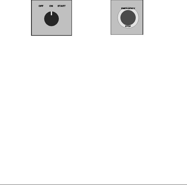
Door Switches
The following switches are mounted on the cabinet door when option F250+Q951 is included:
Operating switch (units with main |
Emergency stop button |
contactor only) |
(optional) |
“START” position closes the main contactor; “ON” position keeps the main contactor closed; “OFF” position opens the main contactor.
The ACS800-PC
21
Diagram
This diagram shows the control interfaces and the main circuit of the drive.
Motor control and I/O board (RMIO)
External control via analogue/digital inputs and outputs
|
|
|
|
|
|
|
|
Input power |
|
~ |
= |
|
|
|
|
|
|
|
|
|
|||
|
|
|
|
|
|||
|
|
|
|
|
|
|
|
|
|
|
|
|
|
|
|
|
|
|
|
|
|
|
|
|
|
|
|
|
|
|
|
Optional module 1: RMBA, RAIO, RDIO, RDNA, RPBA, RCNA, RMBP, RETA or RTAC
Optional module 2: RTAC, RAIO or RDIO
DDCS communication option module:
RDCO-01, RDCO-02 or RDCO-03
= ~ 
 Output power
Brake chopper (optional)
R- UDC+ UDC-
R+
Operation
This table describes the operation of the main circuit in short.
Component |
Description |
|
|
six-pulse rectifier |
converts the three-phase AC voltage to DC voltage |
|
|
capacitor bank |
energy storage which stabilizes the intermediate circuit DC voltage |
|
|
six-pulse IGBT inverter |
converts the DC voltage to AC voltage. The motor operation is controlled |
|
by switching the IGBTs. |
|
|
The ACS800-PC

22
Printed Circuit Boards
The drive contains the following printed circuit boards as standard:
•Main circuit board (AINT)
•Motor control and I/O board (RMIO) with a fibre optic link to the AINT board
•Input bridge control board (AINP)
•Input bridge protection board (AIBP) which includes varistors and snubbers for the thyristors
•Power supply board (APOW)
•Gate driver control board (AGDR)
•Diagnostics and panel interface board (ADPI)
•Brake chopper control board (ABRC) with option +D150
Motor Control
The motor control is based on the Direct Torque Control (DTC) method. Two phase currents and DC link voltage are measured and used for the control. The third phase current is measured for earth fault protection.
The ACS800-PC

23
Mechanical Installation
What this Chapter Contains
This chapter describes the mechanical installation procedure of the drive.
Moving the Unit
Move the transport package by truck and pallet truck to the installation site.
<![if ! IE]><![endif]>) Max 30
WARNING! The ACS800-PC is to be handled and shipped standing up ONLY. This unit is not designed to be laid on its back.
WARNING! Lift the drive by the upper part only using the lifting lugs/bars attached to the top of the unit.
Mechanical Installation

24
Before Installation
Check for external damage. If damage exists, immediately document, contact the shipper and contact ABB.
Delivery Check
The drive delivery contains:
•Drive cabinet including factory installed options such as optional modules (inserted onto the RMIO board in the RDCU unit)
•Residual voltage warning stickers
•Hardware manual
•Appropriate firmware manuals and guides
•Appropriate optional module manuals
•Delivery documents.
Check that there are no signs of damage. Before attempting installation and operation, check the information on the type designation label of the drive to verify that the unit is of the correct type. The label includes a NEMA rating, a type code and a serial number which allow individual recognition of each unit. The first digit of the serial number refers to the manufacturing plant. The next four digits refer to the unit’s manufacturing year and week respectively. The remaining digits complete the serial number so that there are no two units with the same serial number.
The type designation label is located on the inside of the front cover. UL and cUL listing marks are shown on a seperate label.
|
Input |
3PH 48...63Hz |
ABB Inc. |
|
|
Voltage(U1) |
380..500 Vac |
Made in USA of foreign parts |
|
|
Current(I1n) |
498 A |
|
|
|
Short Circuit |
100kA |
|
|
|
Output |
3PH 0...300 Hz |
Mfg. Date: 06-August-2008 |
Orig. Firmware: ASXR734U |
|
Voltage(U2) |
0...U1 Vac |
||
|
Current(I2n) |
515 A |
|
|
|
|
|
|
|
|
Power(Pn) |
400 Hp |
|
|
|
|
|
S/N 2083201813 |
|
|
|
|
|
|
Schematic: 3AUA0000011083 |
|
|
||
ACS800-PC-0400-5+B055+K454+L503+L504+L505+M603
Type designation label
Requirements for the Installation Site
Check the installation site according to the requirements below. Refer to ACS800-PC Dimensional Drawings for frame details. See "Technical Data" for the allowed operation conditions of the drive.
Mechanical Installation

25
Cooling Air Flow
Provide the drive with the amount of clean cooling air given in "Technical Data" / "NEMA Ratings".
Enclosure Ratings
NEMA 1 (NEMA Standard 7-15-1991)
Type 1 enclosures are intended for indoor use primarily to provided a degree of protection against limited amounts of falling dirt.
UL Type 1 (ANSI/UL50)
Indoor use primarily to provide protection against contact with the enclosed equipment and against a limited amount of falling dirt.
Recommendation
NEMA 1 / UL Type 1 enclosures should be applied to clean environments without circulating dust or other contaminants that may collect on surfaces. Equipment of this enclosure rating should be applied to clean electrical room or installed in another enclosure with higher degree of protection. NEMA 1 / UL Type 1 enclosures typically are not the best selection for installation on industrial factory floors.
NEMA 12 (NEMA Standard 7-15-1991)
Type 12 enclosures are intended for indoor use primarily to provide a degree of protection against circulating dust, falling dirt, and dripping noncorrosive liquids.
UL Type 12 (ANSI/UL50)
Indoor use to provide a degree of protection against dust, dirt, fiber flyings, dripping water, and external condensation of noncorrosive liquids.
Recommendation
NEMA 12 / UL Type 12 enclosures should be used in environments that contain circulating dust or other contaminant particles. NEMA 12 / UL Type 12 enclosures are recommended for most applications in industrial factory floor where dust is present but spraying liquids are not.
Regular preventative maintenance of filter changing or cleaning is required. Inspect the enclosure and installed equipment for dust or particle build up that may limit cooling, clean as needed.
Mechanical Installation
26
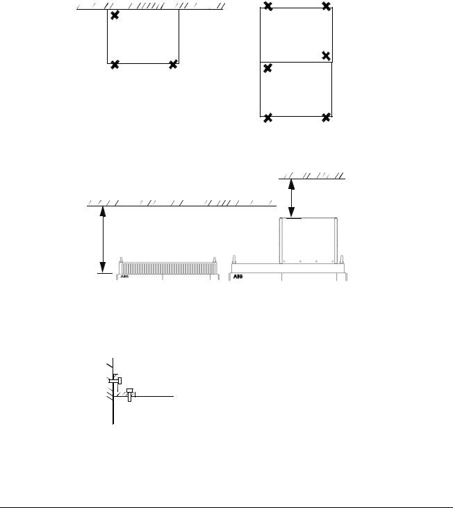
Fastening the Cabinet to the Floor and Wall
Fasten the cabinet to the floor with the fastening holes inside the cabinet. When fastening at the back is not possible, fasten the cabinet at the top using L-brackets bolted to the holes of the lifting lugs (M12 bolt). The cabinet can be fastened against a wall or back to back with another cabinet. Refer to "Dimensional Drawings" for the horizontal and vertical fastening points. Height adjustment can be done by using metal shims between the bottom frame and floor.
Fastening points when installed back against wall
Fastening points when installed back against back
12 in. for fan replacement
15 in.
UL Type 1 |
UL Type 12 |
Top clearance
 L-bracket
M12 bolt
Cabinet top
Fastening the cabinet at the top by using L-brackets (side view)
Mechanical Installation

27
Fastening the Cabinet Through the Holes Inside the Cabinet
The cabinet can be fastened to the floor using the fastening holes inside the cabinet. The maximum allowed distance between the fastening points is 800 mm (31.50 in.).
Fastening bolt: M12 (1/2" to 9/16")
Bottom View
Mechanical Installation

28
Electric Welding
It is not recommended to fasten the cabinet by welding. Cabinets without flat bars at the base
If the preferred fastening methods (clamping or bolting through the holes inside the cabinet) cannot be used, proceed as follows:
•Connect the return conductor of the welding equipment to the cabinet frame at the bottom within 0.5 metres of the welding point.
WARNING! If the welding return wire is connected improperly, the welding circuit may damage electronic circuits in the cabinet. The thickness of the zinc coating of the cabinet frame is 100 to 200 micrometres; on the flat bars the coating is approximately 20 micrometers. Ensure that the welding fumes are not inhaled.
Mechanical Installation

29
Planning the Electrical Installation
What this Chapter Contains
This chapter contains the instructions that you must follow when selecting the motor, cables, protections, cable routing and way of operation for the drive system. Always follow local regulations.
Note: If the recommendations given by ABB are not followed, the drive may experience problems that the warranty does not cover.
To Which Products this Chapter Applies
This chapter applies to the ACS800-01/U1, ACS800-02/U2, ACS800-04/U4, ACS800-PC, and ACS800-07/U7 types up to -0610-X.
Motor Selection and Compatibility
1.Select the motor according to the rating tables in chapter Technical Data. Use the DriveSize PC tool if the default load cycles are not applicable.
2.Check that the motor ratings lie within the allowed ranges of the drive control program:
•Motor nominal voltage is 1/2 … 2 · UN of the drive
•Motor nominal current is 1/6 … 2 · I2hd of the drive in DTC control and
0 … 2 · I2hd in scalar control. The control mode is selected by a drive parameter.
3.Check that the motor voltage rating meets the application requirements:
•The motor voltage is selected according to the AC voltage feeding the drive when the drive is equipped with a diode input bridge (a non-regenerative drive) and will operate in motor mode (i.e. no braking).
•The motor nominal voltage is selected according to “the equivalent AC power source voltage of the drive” if the intermediate DC circuit voltage of the drive is increased from the nominal level by resistor braking or by the control program of a regenerative IGBT line-side converter (parameter selectable function).
The equivalent AC power source voltage for the drive is calculated as follows:
UACeq = UDCmax/1.35
where
UACeq = equivalent AC power source voltage of the drive UDCmax = maximum intermediate DC circuit voltage of the drive See notes 6 and 7 below the "Requirements Table".
Planning the Electrical Installation

30
4.Consult the motor manufacturer before using a motor in a drive system where the motor nominal voltage differs from the AC power source voltage.
5.Ensure that the motor insulation system withstands the maximum peak voltage in the motor terminals. See the "Requirements Table" below for the required motor insulation system and drive filtering.
Example: When the supply voltage is 480 V and the drive is operating in motor mode only, the maximum peak voltage in the motor terminals can be approximated as follows: 480 V · 1.35 · 2 = 1296 V. Check that the motor insulation system withstands this voltage.
Protecting the Motor Insulation and Bearings
The output of the drive comprises – regardless of output frequency – pulses of approximately 1.35 times the equivalent mains network voltage with a very short rise time. This is the case with all drives employing modern IGBT inverter technology.
The voltage of the pulses can be almost double at the motor terminals, depending on the attenuation and reflection properties of the motor cable and the terminals. This in turn can cause additional stress on the motor and motor cable insulation.
Modern variable speed drives with their fast rising voltage pulses and high switching frequencies can generate current pulses that flow through the motor bearings, which can gradually erode the bearing races and rolling elements.
The stress on motor insulation can be avoided by using optional ABB du/dt filters. du/dt filters also reduce bearing currents.
To avoid damage to motor bearings, the cables must be selected and installed according to the instructions given in the hardware manual. In addition, insulated N- end (non-driven end) bearings and output filters from ABB must be used according to the following table. Two types of filters are used individually or in combinations:
•Common mode filter (mainly reduces bearing currents).
•du/dt filter (protects motor insulation system and reduces bearing currents).
Planning the Electrical Installation
 Loading...