


ACS55-01E-04A3-2
Table of contents
 Loading...
ABB ACS55-01E-04A3-2, ACS55-01E-02A2-1, ACS55-01E-09A8-2, ACS55-01E-02A2-2, ACS55-01N-01A4-2 User Manual
...
User's Guide
for type ACS55
AC Drives
from 0.18 to 2.2 kW
ACS55
English EN
Dansk DA
Deutsch DE
Español ES
Suomi FI
Français FR
Italiano IT
Nederlands NL
Português PT
Русский RU
Svenska SV
中文 CN
한국어 KR
GHV Vertriebs-GmbH • 85567 Grafing • Tel: +49 (0) 8092 8189 0 • Fax: +49 (0) 8092 8189 99 • info@ghv.de • www.ghv.de

List of related manuals
Drive manual Code
ACS55 User’s Guide 3AFE68929300
PC tool guide
DriveConfig User’s Guide 3AFE68910897
Maintenance instruction
Guide for Capacitor Reforming 3AFE68735190
GHV Vertriebs-GmbH • 85567 Grafing • Tel: +49 (0) 8092 8189 0 • Fax: +49 (0) 8092 8189 99 • info@ghv.de • www.ghv.de

3
Table of contents
English . . . . . . . . . . . . . . . . . . . . . . . . . . . . . . . . . . . . . . . . . . . . . . . . . . . . . . . . . . . . . . . . . . . . . . . . . . . . . . . .5
Dansk . . . . . . . . . . . . . . . . . . . . . . . . . . . . . . . . . . . . . . . . . . . . . . . . . . . . . . . . . . . . . . . . . . . . . . . . . . . . . . .25
Deutsch . . . . . . . . . . . . . . . . . . . . . . . . . . . . . . . . . . . . . . . . . . . . . . . . . . . . . . . . . . . . . . . . . . . . . . . . . . . . . .45
Español . . . . . . . . . . . . . . . . . . . . . . . . . . . . . . . . . . . . . . . . . . . . . . . . . . . . . . . . . . . . . . . . . . . . . . . . . . . . . .65
Suomi . . . . . . . . . . . . . . . . . . . . . . . . . . . . . . . . . . . . . . . . . . . . . . . . . . . . . . . . . . . . . . . . . . . . . . . . . . . . . . .85
Français . . . . . . . . . . . . . . . . . . . . . . . . . . . . . . . . . . . . . . . . . . . . . . . . . . . . . . . . . . . . . . . . . . . . . . . . . . . . .105
Italiano . . . . . . . . . . . . . . . . . . . . . . . . . . . . . . . . . . . . . . . . . . . . . . . . . . . . . . . . . . . . . . . . . . . . . . . . . . . . . .125
Nederlands . . . . . . . . . . . . . . . . . . . . . . . . . . . . . . . . . . . . . . . . . . . . . . . . . . . . . . . . . . . . . . . . . . . . . . . . . .145
Português . . . . . . . . . . . . . . . . . . . . . . . . . . . . . . . . . . . . . . . . . . . . . . . . . . . . . . . . . . . . . . . . . . . . . . . . . . .165
Русский . . . . . . . . . . . . . . . . . . . . . . . . . . . . . . . . . . . . . . . . . . . . . . . . . . . . . . . . . . . . . . . . . . . . . . . . . . . . .185
Svenska . . . . . . . . . . . . . . . . . . . . . . . . . . . . . . . . . . . . . . . . . . . . . . . . . . . . . . . . . . . . . . . . . . . . . . . . . . . . .205
中文 . . . . . . . . . . . . . . . . . . . . . . . . . . . . . . . . . . . . . . . . . . . . . . . . . . . . . . . . . . . . . . . . . . . . . . . . . . . . . . . .225
한국어 . . . . . . . . . . . . . . . . . . . . . . . . . . . . . . . . . . . . . . . . . . . . . . . . . . . . . . . . . . . . . . . . . . . . . . . . . . . . . .245
3AFE68929300 Rev C
EN, DA, DE, ES, FI, FR, IT, NL, PT, RU, SV, CN, KR
Effective: 2010-04-12
© 2010 ABB Oy. All Rights reserved.
GHV Vertriebs-GmbH • 85567 Grafing • Tel: +49 (0) 8092 8189 0 • Fax: +49 (0) 8092 8189 99 • info@ghv.de • www.ghv.de

4
GHV Vertriebs-GmbH • 85567 Grafing • Tel: +49 (0) 8092 8189 0 • Fax: +49 (0) 8092 8189 99 • info@ghv.de • www.ghv.de

EN 5
User's Guide
for type ACS55
AC Drives
from 0.18 to 2.2 kW
English EN
GHV Vertriebs-GmbH • 85567 Grafing • Tel: +49 (0) 8092 8189 0 • Fax: +49 (0) 8092 8189 99 • info@ghv.de • www.ghv.de

6 EN
3AFE68929300 Rev C
EN
Effective: 2010-04-12
© 2010 ABB Oy. All Rights reserved.
ABB Oy
Drives
P.O. Box 184
FI-00381 HELSINKI
FINLAND
Telephone +358 10 22 11
Fax +358 10 22 22681
Internet www.abb.com/drives
Product and service inquiries
Address any inquiries about the product to your local ABB representative, quoting the type designation and serial number of the unit in
question. A listing of ABB sales, support and service contacts can be found by navigating to www.abb.com/drives
and selecting Sales,
Support and Service network.
Product training
For information on ABB product training, navigate to www.abb.com/drives and select Training courses.
Providing feedback on ABB Drives manuals
Your comments on our manuals are welcome. Go to www.abb.com/drives, then select Document Library – Manuals feedback form (LV
AC drives).
GHV Vertriebs-GmbH • 85567 Grafing • Tel: +49 (0) 8092 8189 0 • Fax: +49 (0) 8092 8189 99 • info@ghv.de • www.ghv.de

EN 7
Safety instructions
Read the following instructions carefully before proceeding with the
installation.
Warning! Dangerous voltage!
Only a competent electrician may install ACS55.
Never work on the drive, the motor cable or the motor when main
power is applied. After switching off the input power, always wait at
least for 5 minutes to let the intermediate circuit capacitors
discharge before you start working on the drive.
Warning! If the heat sink is not earthed properly, you can get an
electric shock if you touch the heat sink.
Note: DIP switches are at a dangerous voltage.
Note: Even when the motor is stopped, dangerous voltages are
present at power circuit terminals L/R, N/S, T1/U, T2/V and T3/W.
Note: Even when the unit is powered down, there may be
dangerous external voltages connected from outside to the relay
output terminals.
Warning! Hot surfaces!
During operation, the cooling element may reach high temperature
(>80°C). Make sure to follow the installation instructions.
General safety instructions
ACS55 starts the motor automatically after a supply break if the
external start signal is on.
Never attempt to repair a broken unit. ACS55 is not a field
repairable unit. Contact the supplier for replacement.
Install ACS55 in a locked or tool-openable space.
Do not connect input power to the unit more than once every three
minutes.
Altering the DIP switches will affect the function and performance
of ACS55. Check that the changes will not cause any risk to
persons or property.
About this manual
This guide provides information necessary to install and start-up
the unit.
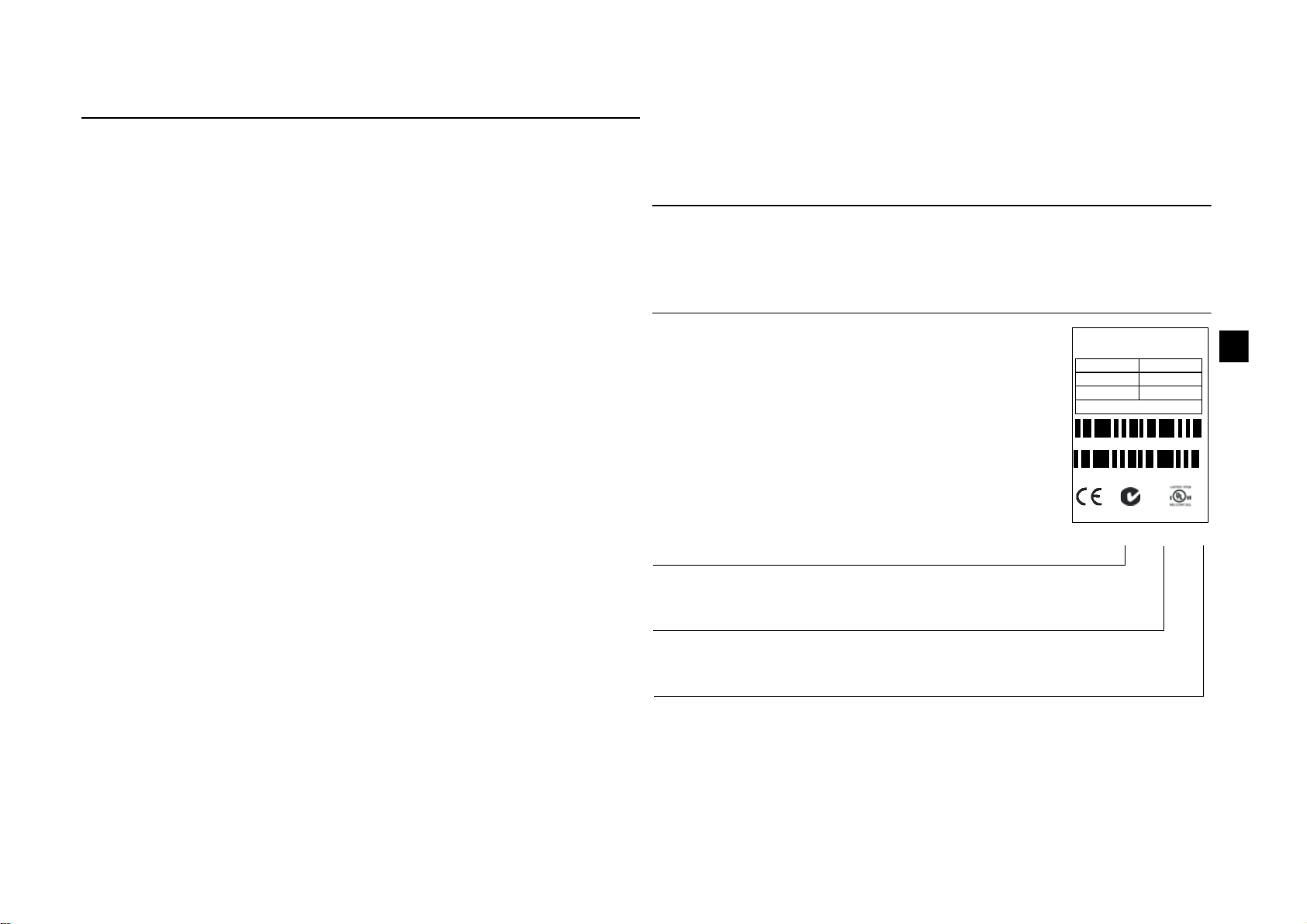
Delivery check
Serial number (S/N) is printed on the rating plate.
(M = manufacturing location, YY = manufacturing year, WW =
manufacturing week, R = product revision number (A, B, C…),
XXXX = integer starting every week from 0001)
U1
f1
I1
U2
f2
I2
ACS55 -01E-09 A8-2
IP20
S/N MYYWWRXXXX
3AFE XX XXXXXX
Pn motor: 2.2 kW (3 HP)
1~ 200..240V
50/60Hz
22.0 A
3~ 0..U1
0..250Hz
9. 8A
RoHS Made in China
ACS55-01_-____-_
The delivery includes:
1. ACS55
2. User’s Guide
3. Two clamps for the control cable (EMC units
only).
Check the rating plate and ensure that the
delivered device corresponds to the order.
EMC filter: E = Built in, N = No
Max. continuous output current (I
2
):
01A4 = 1.4 A, 02A2 = 2.2 A, 04A3 = 4.3 A,
07A6 = 7.6 A, 09A8 = 9.8 A
Supply voltage (U
1
):
1 = 110…120 VAC +10%/-15%
2 = 200…240 VAC +10%/-15%
GHV Vertriebs-GmbH • 85567 Grafing • Tel: +49 (0) 8092 8189 0 • Fax: +49 (0) 8092 8189 99 • info@ghv.de • www.ghv.de
8 EN
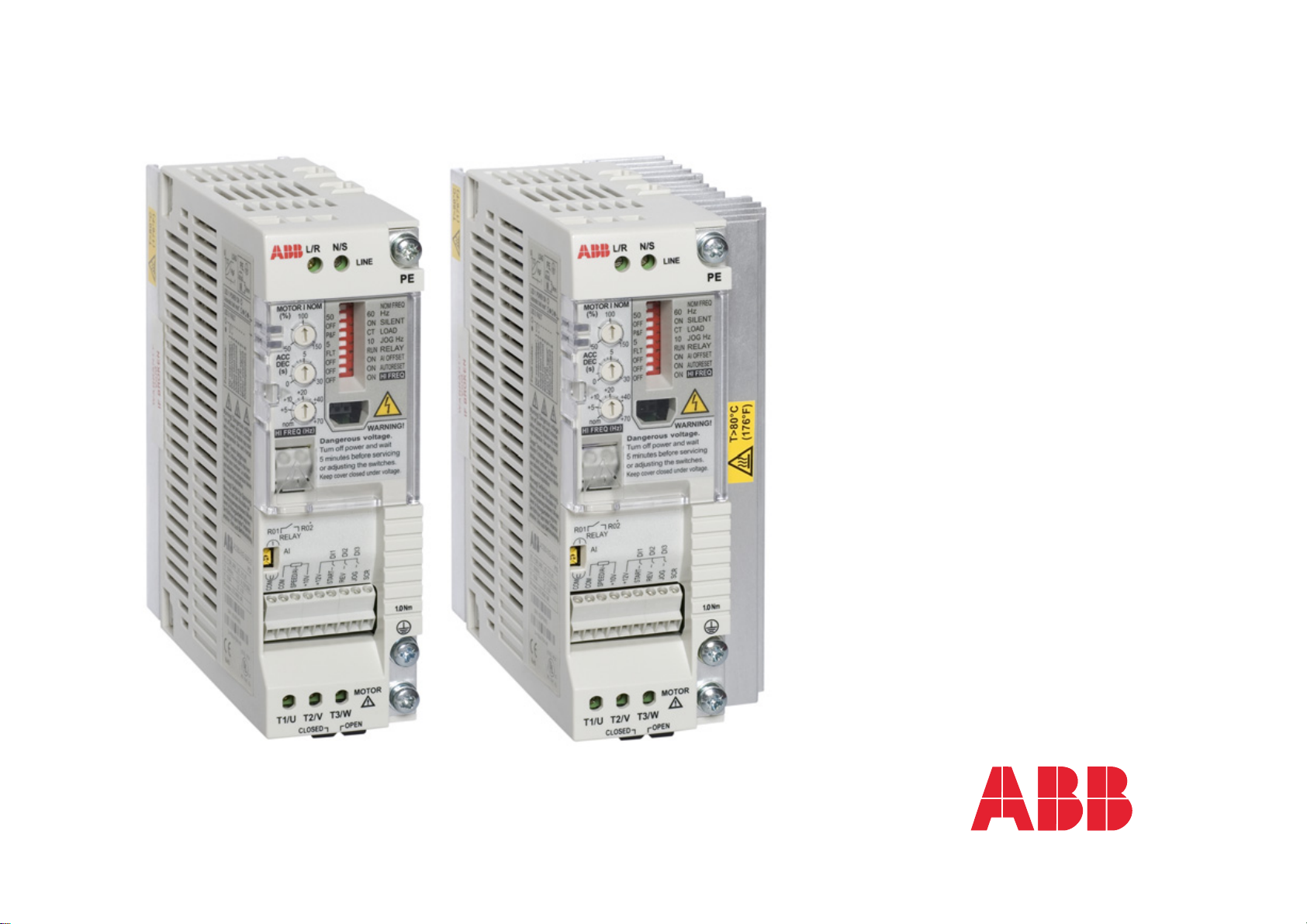
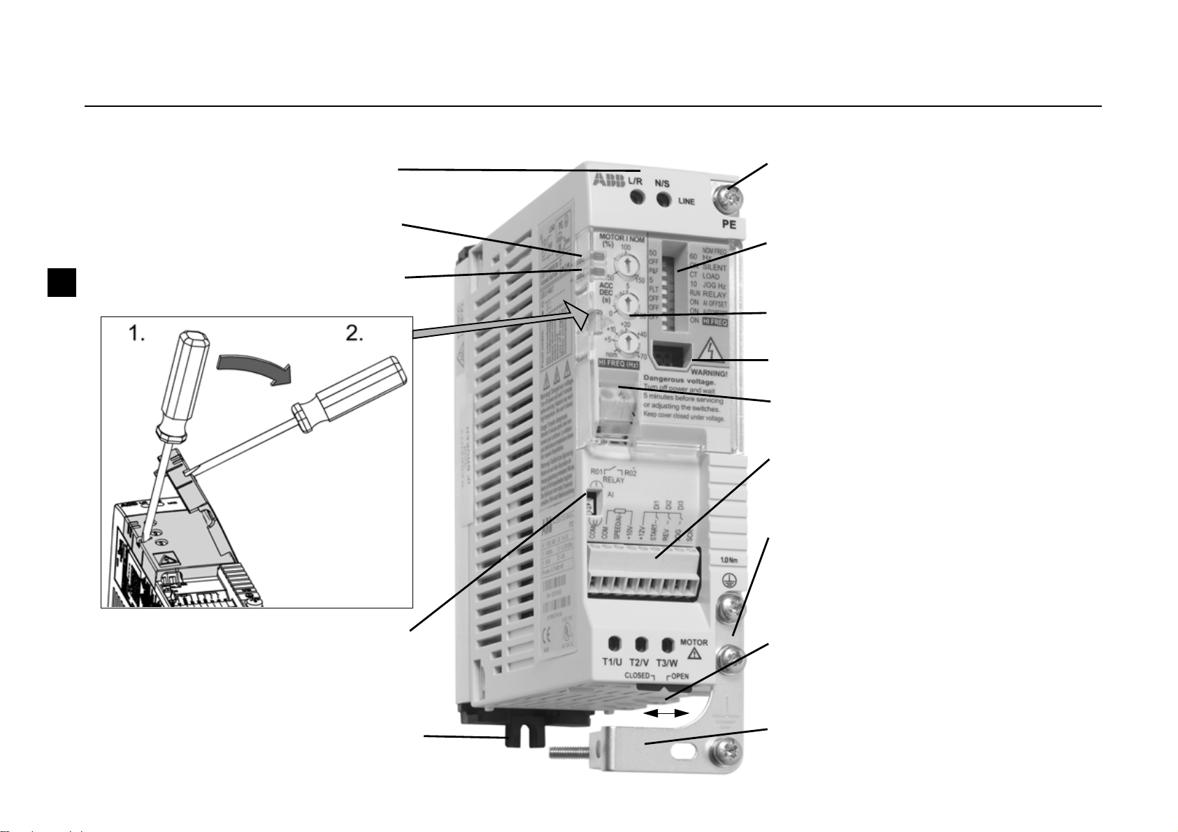
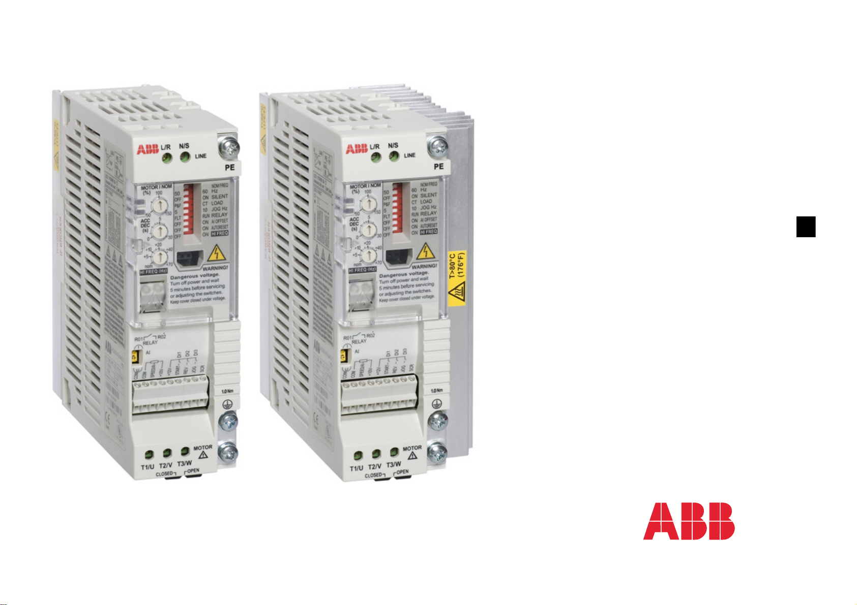
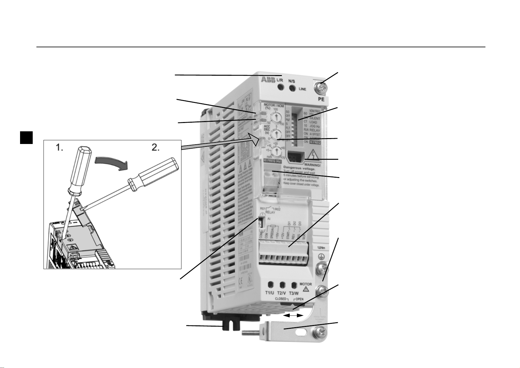
Overview of the unit
ACS55 drive controls the speed of a 3-phase AC induction motor.
Input terminals, page 17
Power on LED, page 21
Fault LED, page 21
Control potentiometers, page 16
Analogue input signal selector
(voltage/current), page 18
Mounting clip, pages 12 - 13
Relay output terminals, page 18
Motor cable terminals, page 17. Sliding
cover provides additional insulation. Slide
the cover left to close.
Protective earth (PE), page 17
DIP switches, page 14
Control cable terminals, page 18
Clamp plate, page 19 (EMC units only)
Motor cable shield, page 17
DriveConfig kit interface, page 24
GHV Vertriebs-GmbH • 85567 Grafing • Tel: +49 (0) 8092 8189 0 • Fax: +49 (0) 8092 8189 99 • info@ghv.de • www.ghv.de

EN 9
Installation and start-up steps
Read Safety instructions on page 7 before proceeding.
Checking the insulation of the assembly
Do not make any voltage tolerance or insulation resistance tests (for example hi-pot or megger) on any part of the drive as testing can
damage the drive. Every drive has been tested for insulation between the main circuit and the chassis at the factory. Also, there are
voltage-limiting circuits inside the drive which cut down the testing voltage automatically.
Action Pg.
1 Check the delivery. 7
2 Ensure that the installation environment is suitable for ACS55. 10
3 Mount the unit. 12 -
13
4 Check applicability of the standard settings: Motor nominal frequency is 50 Hz; load is a pump or a fan; maximum output
frequency is 50 Hz. If the standard settings are not suitable, adjust the DIP switches.
14
5 Make sure the MOTOR I NOM potentiometer matches the rated current of the motor. It defines operation of the motor
thermal protection function.
16
6 Adjust the acceleration/deceleration time potentiometer ACC/DEC if necessary. 16
7 Connect the power supply cable and motor cables. 17
8 Connect the control wires. 18
9 Turn the power on. Green LED is illuminated. Note: Motor rotates if the start signal is active.
10 Set the speed reference and activate the start signal. The motor accelerates to the given speed reference. 20
GHV Vertriebs-GmbH • 85567 Grafing • Tel: +49 (0) 8092 8189 0 • Fax: +49 (0) 8092 8189 99 • info@ghv.de • www.ghv.de

10 EN
Environmental limits
1) When operating the drive in subzero temperatures, keep the input power connected. Install the drive inside an enclosure. Ensure that
heat generated by the drive will be properly dissipated.
Degree of protection of ACS55 is IP20.
Installation site Storage and transportation in a protective package
Air temperature -20°C (-4°F), no frost allowed
1)
+40°C (104°F), with nominal load
+50°C (122°F), if continuous output current is
max. 85% of the nominal output current I
2
+55°C (131°F), if continuous output current is
max. 75% of the nominal output current I
2
-40°C (-40°F) to +70°C (158°F)
Altitude 0…2000 m (0...6,600 ft). At altitudes
1000...2000 m (3,300...6,600 ft), P
N
and I2 are
decreased by 1% for every 100 m.
No limitation
Relative humidity Less than 95%, non-condensing Less than 95%, non-condensing
Contamination
levels
(IEC 60721-3-3)
• No conductive dust allowed
• Air must be clean, free from corrosive
materials and conductive dust
• Chemical gases: Class 3C2
• Solid particles: Class 3S2
Storage Transportation
• No conductive dust allowed
• Chemical gases: Class 1C2
• Solid particles: Class 1S2
• No conductive dust allowed
• Chemical gases: Class 2C2
• Solid particles: Class 2S2
Sinusoidal
vibration
(IEC 60068-2-6)
Frequency range: 5...150 Hz
Constant peak acceleration: 1 g
In accordance with ISTA 1A specification
Shock
(IEC 60068-2-29)
Not allowed Max. 100 m/s
2
(330 ft/s2), 11 ms (36 fts)
Free fall Not allowed Not allowed
GHV Vertriebs-GmbH • 85567 Grafing • Tel: +49 (0) 8092 8189 0 • Fax: +49 (0) 8092 8189 99 • info@ghv.de • www.ghv.de

EN 11
Dimensions
f
e
Frame
A
mm
(in.)
Frame
B
mm
(in.)
Frame
C
mm
(in.)
Frame
D
mm
(in.)
a53
(2.09)72(2.83)74(2.91)74(2.91)
b45
(1.77)
67.5
(2.66)70(2.76)70(2.76)
c 128
(5.04)
128
(5.04)
159
(6.26)
159
(6.26)
d 67.5
(2.66)
67.5
(2.66)
--
e- - 77
(3.03)77(3.03)
f- - 40
(1.57)40(1.57)
g- - 40
(1.57)40(1.57)
h 183
(7.20)
183
(7.20)
-230
(9.06)
i 156
(6.14)
156
(6.14)
182
(7.17)
214
(8.43)
j 170
(6.69)
170
(6.69)
194
(7.64)
226
(8.90)
k 146.5
(5.77)
146.5
(5.77)
171
(6.73)
203
(7.99)
b
a
d
c
g
h
i
j
k
GHV Vertriebs-GmbH • 85567 Grafing • Tel: +49 (0) 8092 8189 0 • Fax: +49 (0) 8092 8189 99 • info@ghv.de • www.ghv.de

12 EN
Mounting
Warning! The unit will warm up to high temperature during normal operation. Ensure sufficient cooling air flow in all conditions:
- Always install ACS55 so that cooling fans are vertical.
- Leave sufficient space around frame A and B units. Frame C and D units are fan cooled, so they can be installed side by side without
extra space between them.
Install the unit using the mounting clip on a 35 mm DIN rail or on a wall.
Mounting on DIN rail
"Click" ACS55 to the rail. Press the
lever on top of the mounting clip to
detach.
Mounting on wall
Install the unit onto the wall through
the mounting clip. Use M4 screws.
Clearance distances
Always leave sufficient space around the unit to ensure
proper cooling.
5 cm
(2 in.)
Frames
A and B
cm (in.)
Frames
C and D
cm (in.)
X 1.5 (0.6) 0 (0)
5 cm
(2 in.)
5 cm
(2 in.)
5 cm
(2 in.)
X
X
X
GHV Vertriebs-GmbH • 85567 Grafing • Tel: +49 (0) 8092 8189 0 • Fax: +49 (0) 8092 8189 99 • info@ghv.de • www.ghv.de
EN 13
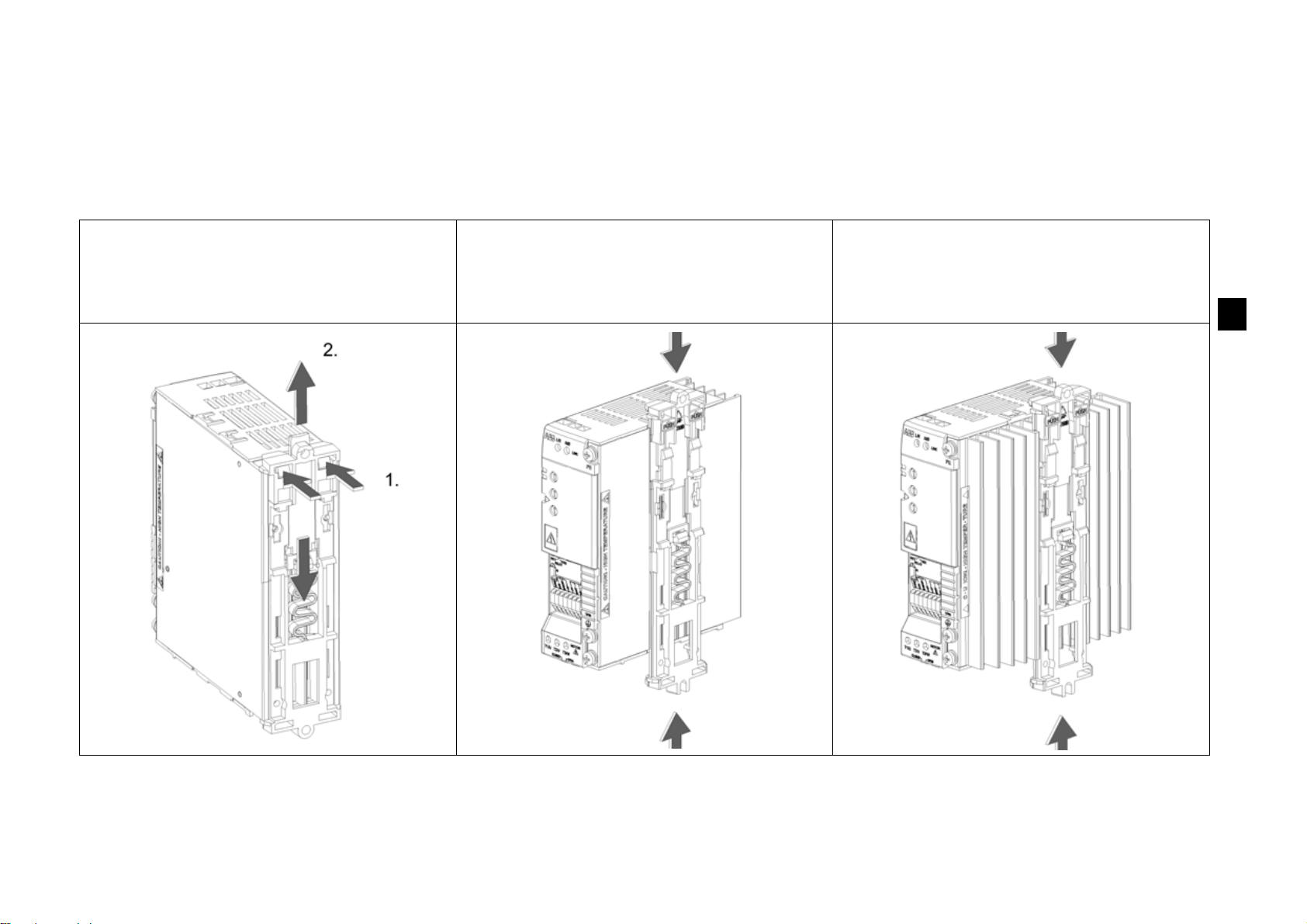
Attaching and detaching the wall mounting clip
The unit can be mounted either with the wide or the narrow side against the wall. Install the mounting clip on the desired side. See
instructions below for frames A and B. Detach the mounting clip of frames C and D by pulling downward and attach it by pushing
upward.
Detaching the mounting clip, Frames A
and B: Press the two plastic buttons to
detach the upper and lower part of the clip
from each other.
Attaching the mounting clip, Frame A:
Place the two parts as shown and click
them together.
Attaching the mounting clip, Frame B:
Push the two parts between the cooling
fins and click them together.
GHV Vertriebs-GmbH • 85567 Grafing • Tel: +49 (0) 8092 8189 0 • Fax: +49 (0) 8092 8189 99 • info@ghv.de • www.ghv.de
14 EN
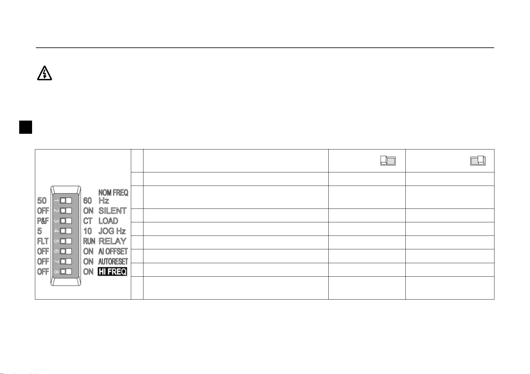
DIP switches
DIP switches are used to adapt ACS55 to the motor and the application.
Warning! The DIP switch is at a dangerous voltage (200 V). Turn off power and wait for 5 minutes before adjusting the switches.
Keep the protective cover closed when ACS55 is powered.
Configuration
• Open the front cover using the tip of a screwdriver, and adjust the DIP switches.
• Use the tip of a screwdriver to slide the switch to the left or right. By default, all switches are in their left position.
• Close the front cover.
Basic information
DIP switch
# Name and function Default
setting
Alternative
setting
1 NOM FREQ HZ: Motor nominal frequency 50 Hz 60 Hz
2 SILENT: Motor noise level (PWM switching
frequency)
OFF - Normal
(5 kHz)
ON - Silent (16 kHz)
3 LOAD: Load torque type (U/f curve) P&F - Pump/fan CT - Constant torque
4 JOG HZ: Constant frequency for the jogging function 5 Hz 10 Hz
5 RELAY: Relay output operation FLT - Fault RUN - Motor running
6 AI OFFSET: Minimum value for analogue input OFF - 0 mA (0 V) ON - 4 mA (2 V)
7 AUTORESET: Automatic fault reset function OFF - No autoreset ON - Autoreset enabled
8 HI FREQ: High frequency mode OFF - Standard ON - High frequency
enabled
GHV Vertriebs-GmbH • 85567 Grafing • Tel: +49 (0) 8092 8189 0 • Fax: +49 (0) 8092 8189 99 • info@ghv.de • www.ghv.de

EN 15
Additional information
For more information, see DriveConfig User’s Guide [3AFE68910897 (English)].
No. Name Information
1NOM
FREQ Hz
Defines the motor nominal frequency (see the motor rating plate).
2 SILENT Defines the drive switching frequency. Note: The higher the frequency the more electromagnetic
noise and the shorter the allowed motor cable length to comply with the European EMC
regulations. See Technical data on page 22. Note: The switching frequency adapts to the
ACS55 temperature.
3 LOAD Optimises the output voltage and frequency characteristics according to the load. Select P&F for
the squared torque (e.g. pumps and fans) and CT for the constant torque loads (e.g. conveyors).
ACS55 automatically boosts the starting voltage 10% to compensate the motor losses and to
increase the starting torque.
4 JOG Hz Defines the jogging frequency. Activate the jogging function on by connecting 12…24 VDC to digital input 3 ("JOG").
(Drive accelerates or decelerates to the jogging frequency, and keeps it until the input is switched off.)
5 RELAY Selects the drive state the normally open contact of the relay output indicates. FLT = Fault. Contact is opened while
at a fault state or at a power off state. RUN = Running. Contact is closed while running.
6AI
OFFSET
Activates a living zero supervision for the analogue input. 4 mA (2 V) = ACS55 trips on a fault if the value drops
below the limit. See section Speed controlling on page 20 for information on analogue input scaling.
7AUTO-
RESET
Activates the automatic reset function for the following faults: Undervoltage, overvoltage, analogue input loss.
ON = ACS55 will try to reset automatically three seconds after a fault trip. Maximum number of resets is ten in three
minutes. If exceeded, ACS55 stops and will not attempt a new reset. See also Status indications and fault tracing on
page 21.
Warning! If the start signal is on, the motor will be started after a reset. Make sure that this will not cause danger.
8 HI FREQ Defines the maximum output frequency. OFF: Max. frequency = value defined by the NOM FREQ HZ switch. ON:
Max. frequency = value defined by the NOM FREQ HZ switch + value of HI FREQ potentiometer. See Control
potentiometers on page 16.
U
f
CT
P&F
f
N
U
N
10%
GHV Vertriebs-GmbH • 85567 Grafing • Tel: +49 (0) 8092 8189 0 • Fax: +49 (0) 8092 8189 99 • info@ghv.de • www.ghv.de

16 EN
Control potentiometers
The control potentiometers can be adjusted using a screwdriver. By default, all potentiometers are in their middle position.
MOTOR I
NOM
Calculate MOTOR I NOM with the equation below or pick a value from the MOTOR I NOM selection chart
below. ACS55 estimates the temperature of the motor based on the measured output current and the
defined motor nominal current. The drive trips if the estimated temperature implies motor overheating.
Note: If motor cables are long causing large capacitive currents, it might be necessary to increase the
MOTOR I NOM setting.
ACC/DEC Defines the acceleration and deceleration time from minimum to maximum frequency and vice versa in
seconds. The longer the ACC/DEC time, the more slowly ACS55 will follow the given reference.
HI FREQ Limits the output frequency to a desired value between nominal frequency and nominal frequency + 70 Hz.
To use this potentiometer, turn the high frequency mode on with the HI FREQ DIP switch. See DIP switches
on page 14.
MOTOR I NOM (%) =
Motor nominal current [A]
ACS55 nominal current [A]
• 100%
ACS55-01x-
-01A4-x
0,7 0,8 1,0 1,2
1,4
1,6 1,8 2,0 2,1
-02A2-x
1,11,31,51,82,0
2,2
2,4 2,6 2,8 3,0 3,3
-04A3-x
2,2 2,6 3,0 3,5 4,0
4,3
4,7 5,2 5,6 6,0 6,5
-07A6-x
3,84,65,36,16,8
7,6
8,4 9,3 10,2 11,4
-09A8-x
4,95,96,97,88,8
9,8
10,8 12,0 13,3 14,7
MOTOR I NOM
50 60 70 80 90
100
110 120 130 140 150%
Ref. [%]
t
100
ACC/DEC
MOTOR I NOM selection chart
ACC/DEC time
Motor nominal current (A)
GHV Vertriebs-GmbH • 85567 Grafing • Tel: +49 (0) 8092 8189 0 • Fax: +49 (0) 8092 8189 99 • info@ghv.de • www.ghv.de
EN 17
Connecting power supply and motor
Warning! Before installation ensure that the main supply is off.
Note: Ensure power supply is correct! Connecting 230 VAC to the ACS55 unit rated for 115 VAC input will damage
the drive!
Warning! If the heat sink is not earthed properly, you can get an electric shock if you touch the heat sink.
Note: Use only supplied M4x8 Combi screws. Maximum allowed intrusion depth for the grounding screws is
6mm.
Follow local rules for cable cross sections. Use 60°C (140°F) rated power cable, or 75°C (167°F) rated cable if
ambient temperature is above 30°C (86°F). See also Additional cabling and EMC instructions on page 19.
Earth leakage current of the ACS55 can exceed 3.5 mA AC / 10 mA DC. According to EN50178, ACS55 may only
be used in permanent installation.
Input fuse
See Technical data on page 22 for recommended fuse types.
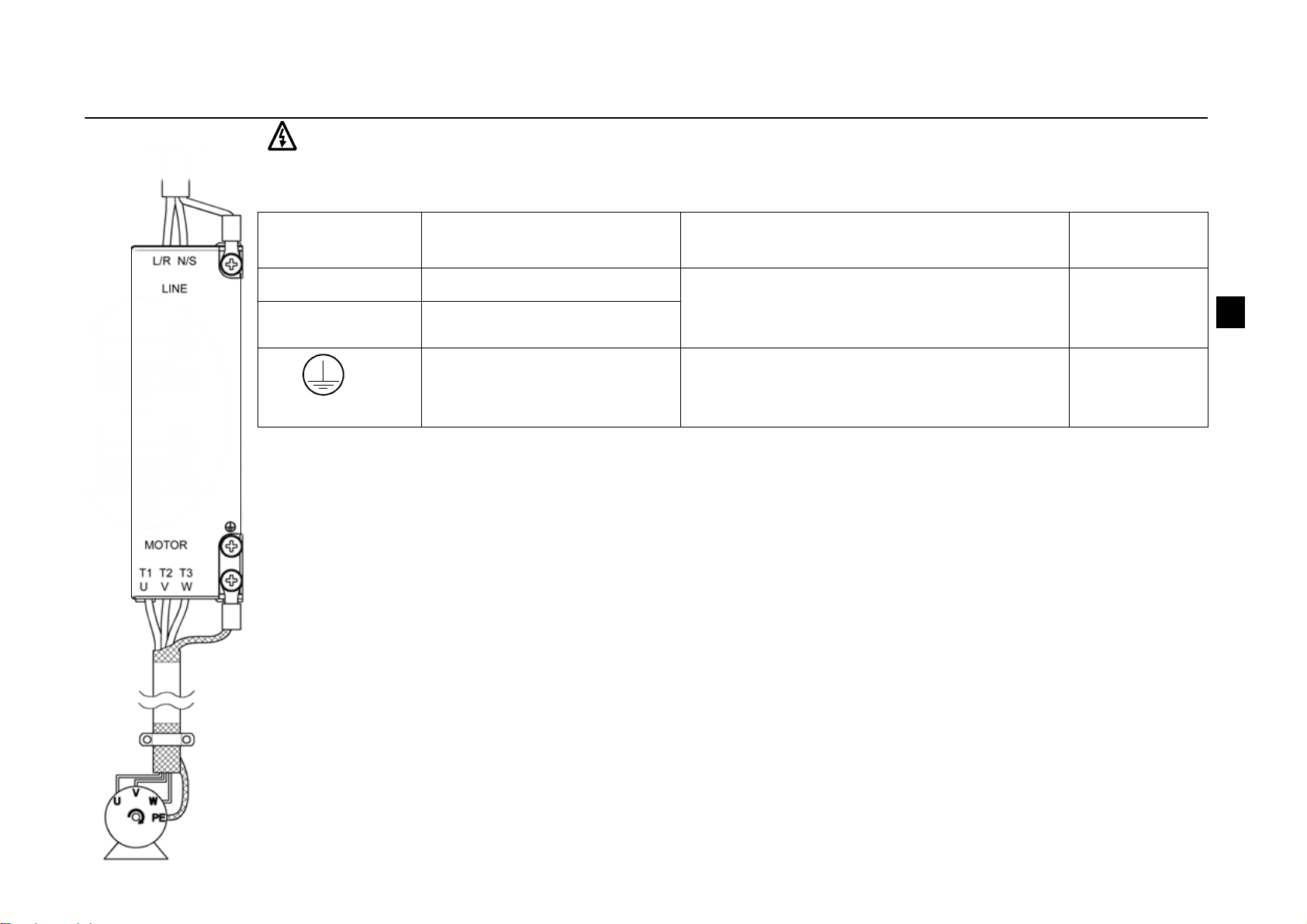
Motor
The motor must be a 3-phase AC induction motor, with nominal voltage U
N
from 200 to 240 V and nominal
frequency f
N
either 50 or 60 Hz. Motor nominal current must be less than or equal to the nominal output current (I2)
of the drive.
If the phases are connected, U-U, V-V and W-W, and the selected direction is forward, the shaft rotates clockwise
as seen from the drive shaft end.
Terminal Description Wire size Tightening
torque
L/R, N/S 1~ power supply input Max. 2.5 mm
2
(frames A and B) or max.
4mm
2
(frames C and D) four conductor
cable
0.5 N·m
T1/U, T2/V, T3/W Power output to motor
PE Protective earth.
Motor cable protective
conductor and shield.
Use multi-strand copper wire. Size of the
wire is not allowed to be smaller than the
size of the power cable used.
1 N·m
1-phase
input voltage
GHV Vertriebs-GmbH • 85567 Grafing • Tel: +49 (0) 8092 8189 0 • Fax: +49 (0) 8092 8189 99 • info@ghv.de • www.ghv.de
18 EN
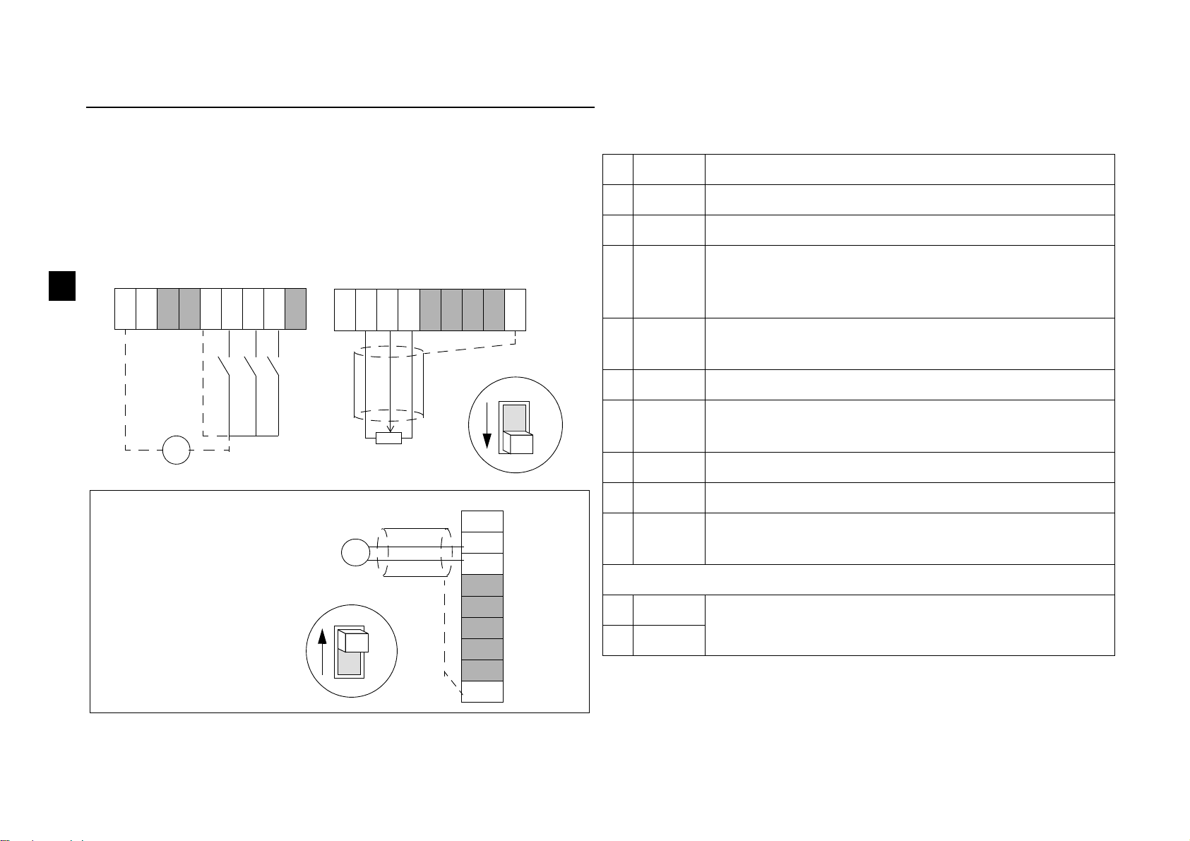
Connecting control wires
Internal (1) or external (2) power supply can be used for the digital
inputs. Analogue control voltage is 0…10 VDC as default. (The AI
jumper must be in voltage ("U") position).
Control terminals
• Conductor size: stranded 0.25…1.5 mm
2
(AWG 23 to AWG 16)
• Tightening torque: 0.25 N·m.
1) Connected internally to frame (earth) through 1 Mohm resistor.
2) Digital input impedance is 1.5 kohm.
Using 0/4…20 mA current signal:
- Change AI jumper to current
("I") position.
- Set AI OFFSET switch to ON
position if 4…20 mA current
signal is desired.
SCR
START
REV
JOG
+-
2)
1)
U
I
12...24 VDC supply
+12V
COM
SPEED/AI
+10V
COM
SCR
START
REV
JOG
+12V
COM
SPEED/AI
+10V
COM
AI
U
I
AI
SCR
START
REV
JOG
+12V
COM
SPEED/AI
+10V
COM
+-
1...10 kohm
# Name Description
1 COM Common for digital or analogue inputs
1)
2 COM Common for digital or analogue input
1)
3 AI Analogue input: Speed (frequency) reference.
0/2…10 VDC (Ri=190 kohm), or 0/4…20 mA
(Ri=100 ohm). Resolution 0.1%, accuracy +/-1%.
4 +10V Reference voltage for analogue input.
Accuracy +/-2%. Max. 10 mA.
5 +12V Auxiliary voltage for digital inputs. Max. 30 mA.
6 START Digital input 1: Start (resets the drive after a fault
trip)
2)
7 REV Digital input 2: Reverse rotation direction
2)
8 JOG Digital input 3: Activate jog speed
2)
9 SCR Earth for signal cable screen. Connected internally
to frame earth.
Relay output
1 RO1 Fault: Relay opens.12 V...250 VAC / 30 VDC
10 mA...2 A
2RO2
GHV Vertriebs-GmbH • 85567 Grafing • Tel: +49 (0) 8092 8189 0 • Fax: +49 (0) 8092 8189 99 • info@ghv.de • www.ghv.de
EN 19
Additional cabling and EMC instructions
Follow these instructions for trouble free operation and to ensure compatibility with the European EMC directive.
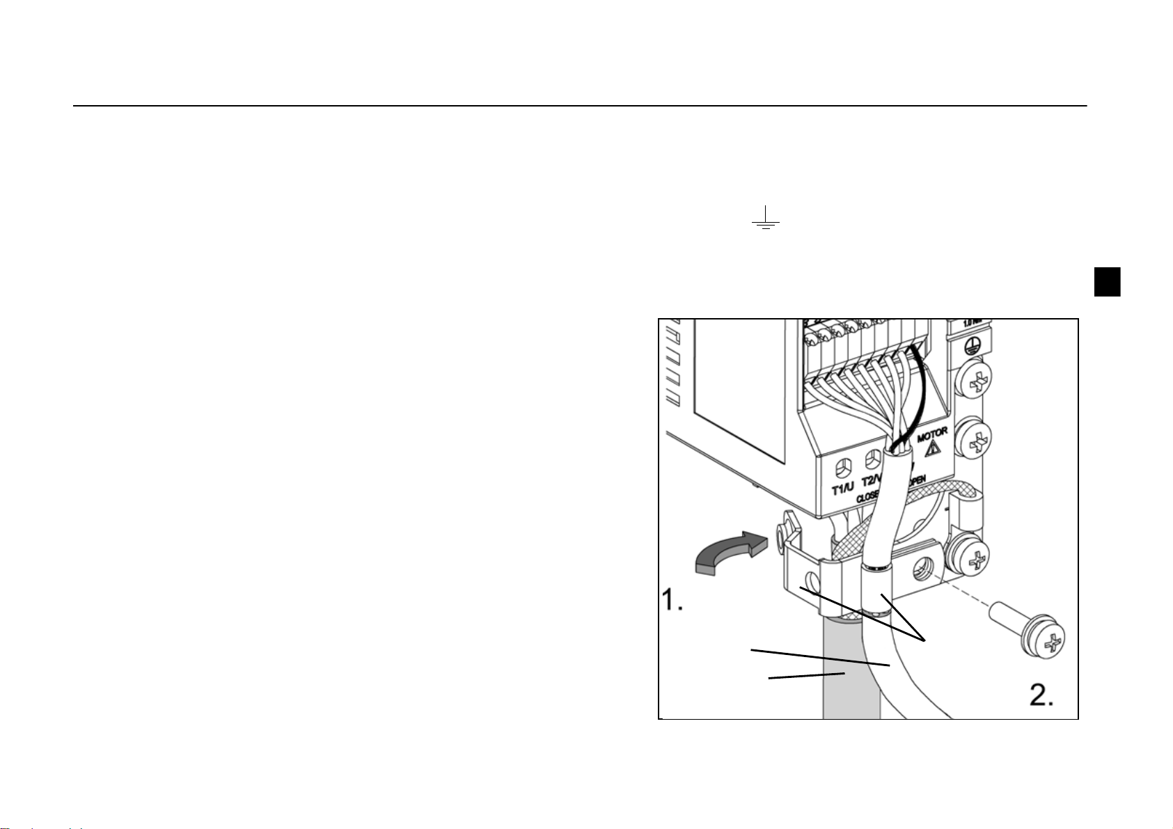
Motor cable
The motor cable must be a symmetrical three conductor cable with a concentric PE conductor or a four conductor cable with a
concentric shield. Braided metallic screen is recommended, e.g. type MCCMK (NK Cables).
- Twist the cable screen wires together into a bundle, and connect to the earthing terminal . Keep the bundle as short as possible.
- Clamp the cable screen as shown in the figure when internal or external EMC filter is used.
- At the motor end the motor cable screens must be earthed 360 degrees with an EMC cable gland or the screen wires must be twisted
together into a bundle not longer than 5 times its width and connected to the PE terminal of the motor.
Control cables
Control cables must be multi-core cables with a braided copper wire screen.
A double shielded twisted pair cable is recommended for the analogue
signals.
- Twist the screen together into a bundle and connect to terminal SCR. Keep
the bundle as short as possible.
- Clamp the control cable as shown in the figure (EMC units only).
- Route the motor cable away from the control wires and the power supply
cable to avoid electromagnetic interference (distance > 20 cm).
Note: Never mix 24 VDC and 115/230 VAC signals in the same cable.
control cable
motor cable
clamps
GHV Vertriebs-GmbH • 85567 Grafing • Tel: +49 (0) 8092 8189 0 • Fax: +49 (0) 8092 8189 99 • info@ghv.de • www.ghv.de
20 EN
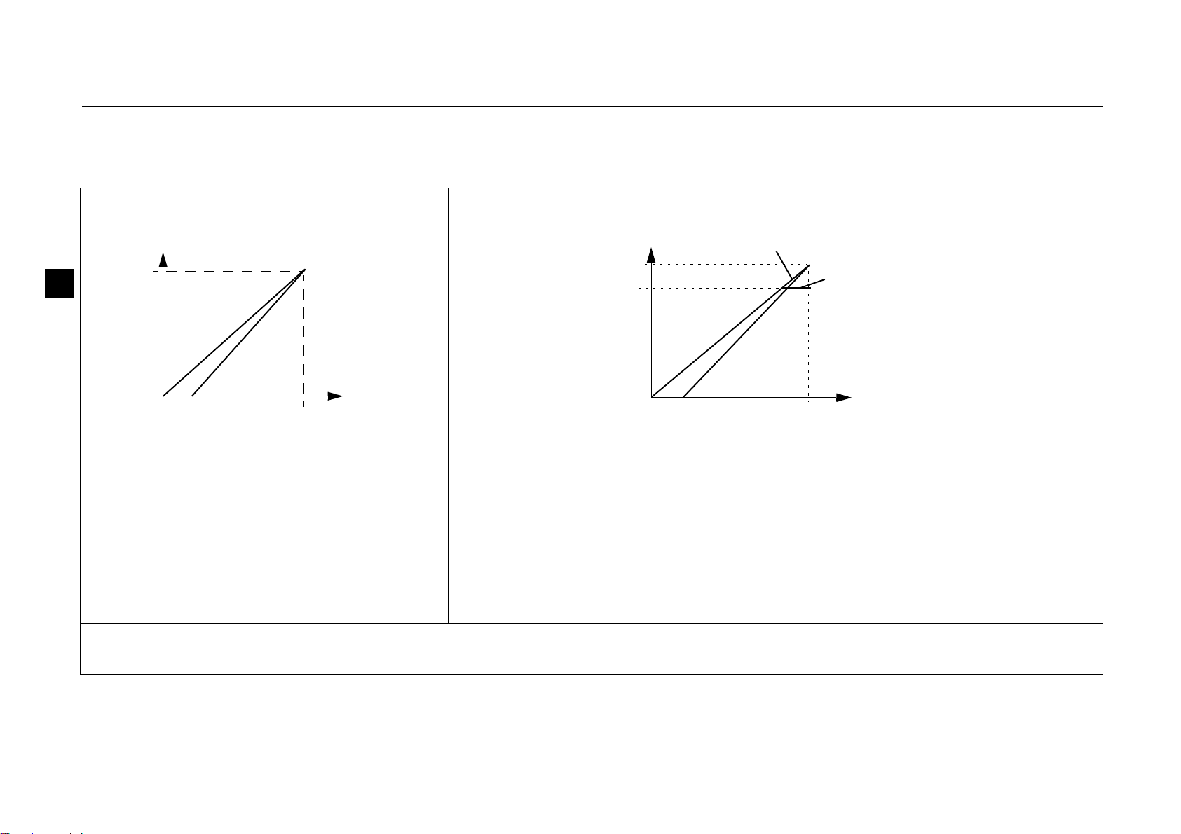
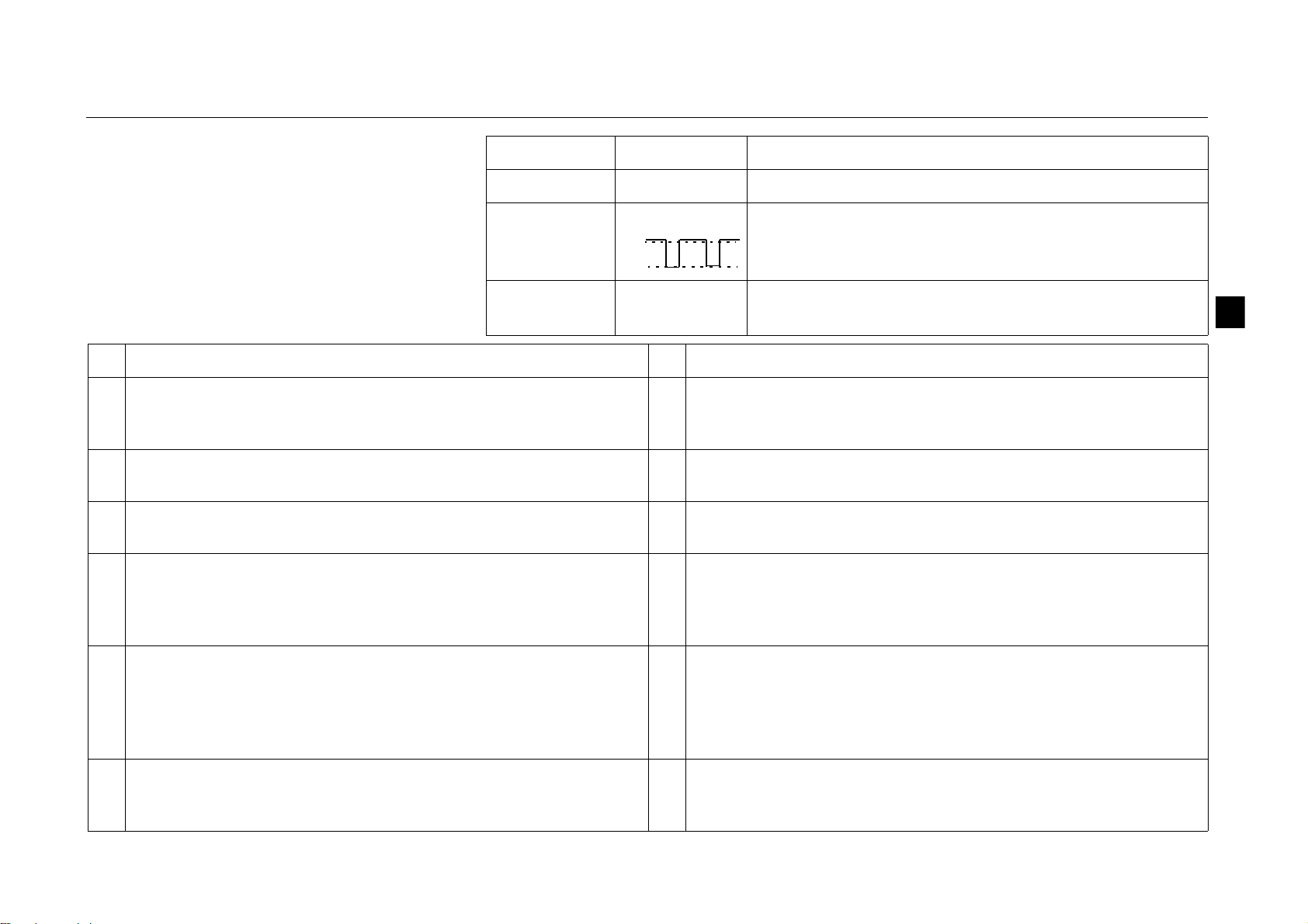
Speed controlling
The analogue input gives the speed (frequency) reference for ACS55. The correspondence between the analogue input and the
reference depends on the settings of the DIP switches as shown below. Output frequency follows the reference changes as defined by
the ACC/DEC potentiometer.
High frequency mode OFF (default) High frequency mode ON
DIP switch settings:
HI FREQ = OFF
AI OFFSET = OFF (curve a) or ON** (curve b)
MOTOR NOM FREQ = 50 or 60 Hz
DIP switch settings:
HI FREQ = ON
AI OFFSET = OFF (curve a) or ON** (curve b)
MOTOR NOM FREQ = 50 or 60 Hz
The output frequency is limited to the selected
nominal frequency of the motor.
Actual output frequency is limited to a value between f
N
and fN + 70 Hz by the
HI FREQ potentiometer. The potentiometer does not affect the scaling of the
analogue input.
* Use AI jumper to select voltage or current signal. See page 18.
** To protect the drive against analogue input signal loss, the drive trips if the signal value is below 2 V (4 mA).
f
Input*
10 V
f
N
[V, mA]
0
2 V
4 mA
a
b
20 mA
f
Input*
10 V
[V, mA]
0
f
N
+ 70 Hz
frequency reference
f
N
output frequency limit
2 V
4 mA
a
b
20 mA
GHV Vertriebs-GmbH • 85567 Grafing • Tel: +49 (0) 8092 8189 0 • Fax: +49 (0) 8092 8189 99 • info@ghv.de • www.ghv.de
EN 21
Status indications and fault tracing
(*) Automatically reset if the AUTORESET is ON. See DIP switches on page 14.
ACS55 has two status indication LEDs, visible
through the front cover.
If the drive detects a problem, the red LED will
blink. After fixing the problem, reset by
switching the start signal off. If start is off
already, turn it first on and then off again.
See the table below for the fault codes (= the
number of LED blinks).
Green LED Red LED Description
On Off ACS55 operates normally.
On Blinking Protective function has been activated. Number of
blinks indicates the fault code.
Blinking Blinking
ACS55 will reset automatically within 3 seconds. (*)
Warning! Motor starts, if start signal is on.
# Possible causes and what to do # Possible causes and what to do
1 DC overvoltage (*). 1) Mains voltage is too high: Check supply.
2) Deceleration ramp time is too short compared to the load inertia:
Increase ACC/DEC time with potentiometer.
7 Motor overload (I2t overload): 1) Check the load, and verify that
the motor size is suitable for ACS55. 2) Verify that setting of
MOTOR I NOM potentiometer is correct.
2 DC undervoltage (*). Mains voltage is too low: Check supply. 8 Inverter overload or excessive internal temperature: 1) Load is too
high or 2) drive cooling is insufficient.
3 Output short circuit: Switch off the power and check the motor
windings and motor cable.
9 Other fault. Internal error. Turn power off and on again. If problem
persists, replace the unit.
4 Output overcurrent. 1) Acceleration time is too short compared to
the load inertia: Increase ACC/DEC time with potentiometer. 2)
Motor and drive sizes do not match: Check motor.
10 Parameterization fault. Note: Both LEDs will blink. DIP switches
have been moved from default setting after the drive has been
parameterized with DriveConfig tool. Put the switches back to
default position.
5 Reserved 11 Drive is battery-powered. Drive status indicates Fault, because it is
not possible to start the drive. For drive operation, the drive must
be connected to mains. However, when the drive is powered from
the DriveConfig kit supply, the connection between DriveConfig
and the drive is OK.
6 Analogue input value is less than 4 mA/2 V. (*) Note: This
supervision is active if AI OFFSET is ON.
12 Drive has been controlled by DriveConfig (or other application via
serial communication) and the communication has been lost.
Check the communication.
On
Off
12
GHV Vertriebs-GmbH • 85567 Grafing • Tel: +49 (0) 8092 8189 0 • Fax: +49 (0) 8092 8189 99 • info@ghv.de • www.ghv.de

22 EN
Technical data
* Allowed for 1 minute.
** Recommended values. Do not use ultra rapid or low peak fuses. Follow local rules.
230 V 115 V
Built-in EMC, ACS55-01E- 01A4-2 02A2-2 04A3-2 07A6-2 09A8-2 01A4-1 02A2-1
No EMC, ACS55-01N- 01A4-2 02A2-2 04A3-2 07A6-2 09A8-2 01A4-1 02A2-1
Motor continuous output power kW 0.18 0.37 0.75 1.5 2.2 0.18 0.37
hp 1/4 1/2 1 2 3 1/4 1/2
Frame size (no EMC) A A B C C A A
Frame size (EMC) AABDDAA
Nominal ratings
Input voltage U
1
V 200…240 (+10/-15%) 110…120 (+10/-15%)
Continuous output current I
2
A 1.4 2.2 4.3 7.6 9.8 1.4 2.2
Max. output current I
2max
* A 2.1 3.3 6.5 11.4 14.7 2.1 3.3
Output voltage U
2
V0…U1, 3-phase 0…2×U1, 3-phase
Input current I
1
A 4.4 6.9 10.8 18.2 22.0 6.4 9.5
Switching frequency kHz 5 (max. 16)
Protection limits
Overcurrent (peak) A 4.4 6.9 13.5 23.9 30.9 4.4 6.9
Overtemperature 95°C / 203°F (heat sink)
Maximum wire sizes
Power terminals mm
2
2.5 (AWG 14) 4 (AWG 12) 2.5 (AWG 14)
Control terminals mm
2
1.5 (AWG 16)
Power losses W213251741032435
Line fuse size**
IEC, type IEC269 gG A10161625321016
UL, types CC and T A 10 15 20 25 30 10 15
Weight, Built-in EMC, ACS55-01E- kg (lb) 0.65 (1.4) 0.7 (1.5) 0.9 (2) 1.6 (3.5) 1.7 (3.7) 0.65 (1.4) 0.7 (1.5)
Weight, No EMC, ACS55-01N- kg (lb) 0.65 (1.4) 0.7 (1.5) 0.9 (2) 1.2 (2.6) 1.3 (2.9) 0.65 (1.4) 0.7 (1.5)
GHV Vertriebs-GmbH • 85567 Grafing • Tel: +49 (0) 8092 8189 0 • Fax: +49 (0) 8092 8189 99 • info@ghv.de • www.ghv.de
EN 23
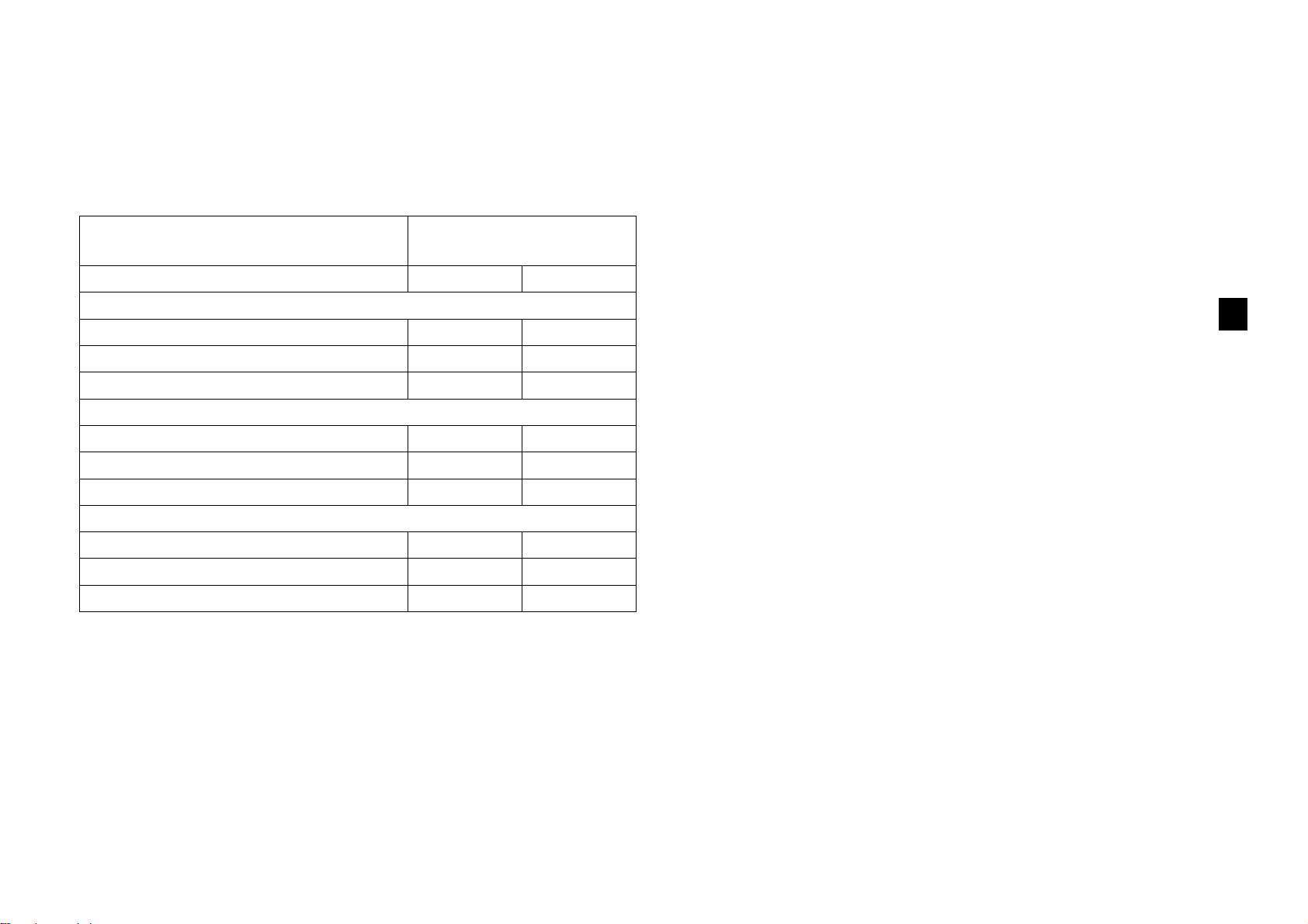
Maximum motor cable lengths
To comply with European EMC regulations, the motor cable length
has to be limited as specified in the table below. The shorter the
motor cable, the lower the noise emissions to the supply line and
the environment.
1) Switching frequency can be selected with the DIP switch. See
page 15.
2) Applicable for conducted emissions only.
3) Applicable for conducted and radiated emissions.
Protections
Overvoltage, undervoltage, output short circuit, overcurrent,
analogue input loss, motor overload, inverter overload.
Distribution networks isolated from earth
Drives with built-in EMC filter must not be used in a floating network
or in a high impedance earthed industrial distribution network.
Environmental information
A product to be disposed contains valuable raw material that
should be recycled, thus preserving energy and natural resources.
Instructions for disposal are available from ABB sales and service
companies.
Liability limits
The manufacturer is not responsible for:
• Any costs resulting from a failure if the installation,
commissioning, repair, alteration or ambient conditions of the
drive do not fulfil the requirements specified in the
documentation delivered with the unit and other relevant
documentation.
• Units subjected to misuse, negligence or accident.
• Units comprised of materials provided or designs stipulated by
the purchaser.
In no event shall the manufacturer, its suppliers or subcontractors
be liable for special, indirect, incidental or consequential damages,
losses or penalties.
If you have any question concerning your ABB drive, please
contact the local distributor or ABB office. The technical data,
information and specifications are valid at the time of printing.
The manufacturer reserves the right to modifications without prior
notice.
Converter type
ACS55-01x-
Switching frequency
Built-in EMC filter 5 kHz 16 kHz
1)
EN61800-3, First environment, unrestricted distribution
2)
01A4-2, …, 04A3-2 10 m 3 m
01A4-1, 02A2-1 10 m 3 m
07A6-2, 09A8-2 10 m 3 m
EN61800-3, First environment, restricted distribution
3)
01A4-2, …, 04A3-2 10 m 10 m
01A4-1, 02A2-1 10 m 10 m
07A6-2, 09A8-2 20 m 10 m
EN61800-3, Second environment
3)
01A4-2, …, 04A3-2 10 m 10 m
01A4-1, 02A2-1 10 m 10 m
07A6-2, 09A8-2 30 m 10 m
GHV Vertriebs-GmbH • 85567 Grafing • Tel: +49 (0) 8092 8189 0 • Fax: +49 (0) 8092 8189 99 • info@ghv.de • www.ghv.de
24 EN
Approvals
CE
The ACS55 complies with the requirements of the European
• Low Voltage Directive 73/23/EEC with amendments
• EMC Directive 89/336/EEC with amendments.
Corresponding declarations and a list of main standards are
available on request.
Electromagnetic compatibility:
The ACS55 fulfils the following standards provided that installation
is done properly and according to the instructions of this manual:
1) Observe the maximum allowed motor cable lengths and
switching frequency, page 23. See also cabling instructions on
page 19.
The current harmonic levels can be reduced by fitting external input
chokes.
UL, cUL and C-Tick markings
See the rating plate.
UL, cUL:
The ACS55 is suitable for use on a circuit capable of delivering not
more than 65 kA rms symmetrical amperes, 230 volts maximum,
when protected by CC or T class fuses.
C-Tick:
For the electromagnetic compatibility, see the specification in
section CE above.
Compliance with the European Machinery Directive
The drive complies with the European Machinery Directive
requirements for an equipment intended to be incorporated into
machinery. The declaration of incorporation is available from ABB.
Product protection in the USA
This product is protected by one or more of the following US
patents
Other patents pending.
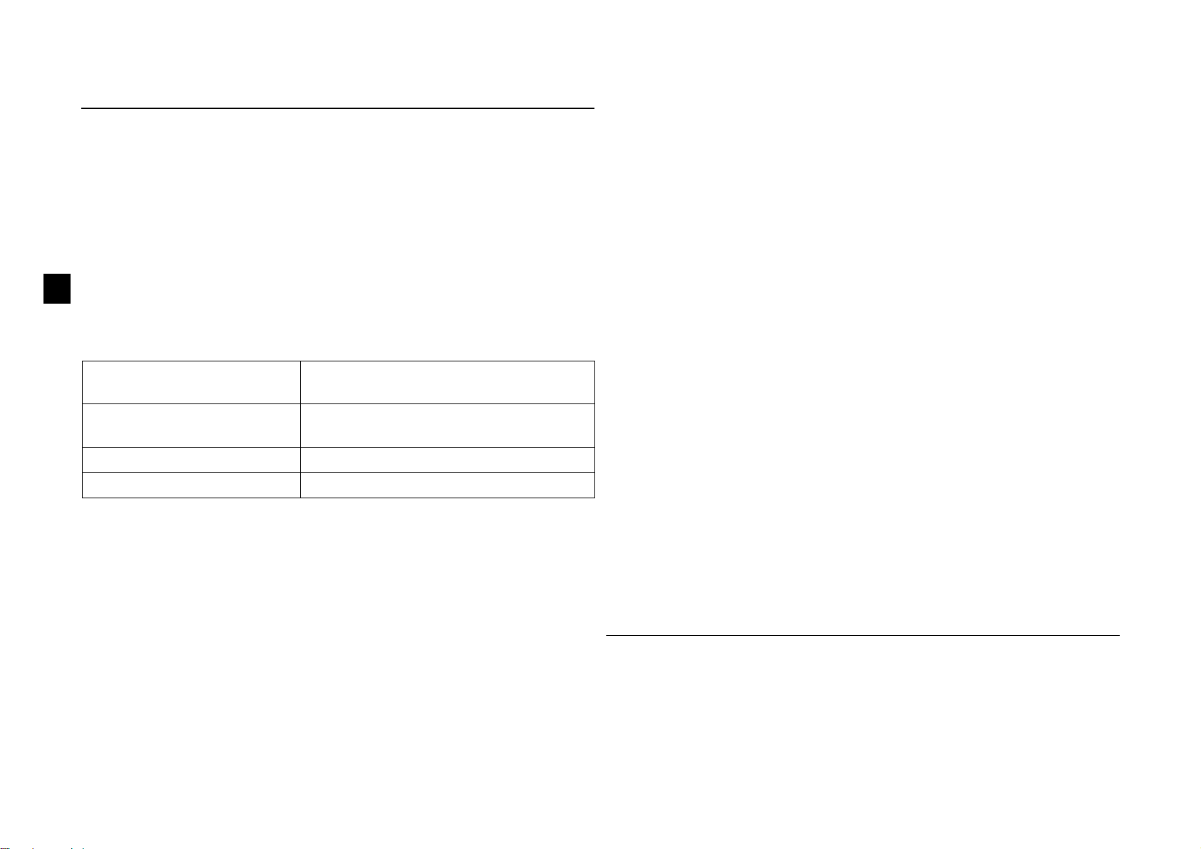
Accessories
Input chokes: CHK-A1, CHK-B1, CHK-C1, CHK-D1
Output choke: ACS-CHK-B3, ACS-CHK-C3
Potentiometer unit: ACS55-POT
DriveConfig kit, for more information please contact your local ABB
office. See DriveConfig User’s Guide [3AFE68910897 (English)].
Conductive high frequency
emissions
EN61800-3 first environment, unrestricted/
restricted distribution
1)
Radiated high frequency
emissions
EN61800-3 first environment, restricted
distribution
Immunity EN61800-3 second environment
Line current harmonics IEC61000-3-2
4,920,306 5,301,085 5,463,302 5,521,483 5,532,568 5,589,754 5,612,604
5,654,624 5,799,805 5,940,286 5,942,874 5,952,613 6,094,364 6,147,887
6,175,256 6,184,740 6,195,274 6,229,356 6,252,436 6,265,724 6,305,464
6,313,599 6,316,896 6,335,607 6,370,049 6,396,236 6,448,735 6,498,452
6,552,510 6,597,148 6,600,290 6,741,059 6,774,758 6,844,794 6,856,502
6,859,374 6,922,883 6,940,253 6,934,169 6,956,352 6,958,923 6,967,453
6,972,976 6,977,449 6,984,958 6,985,371 6,992,908 6,999,329 7,023,160
7,034,510 7,036,223 7,045,987 7,057,908 7,059,390 7,067,997 7,082,374
7,084,604 7,098,623 7,102,325 7,109,780 7,164,562 7,176,779 7,190,599
7,215,099 7,221,152 7,227,325 7,245,197 7,250,739 7,262,577 7,271,505
7,274,573 7,279,802 7,280,938 7,330,095 7,349,814 7,352,220 7,365,622
7,372,696 7,388,765 7,408,791 7,417,408 7,446,268 7,456,615 7,508,688
7,515,447 7,560,894 D503,931 D510,319 D510,320 D511,137 D511,150
D512,026 D512,696 D521,466 D541,743S D541,744S D541,745S
D548,182S D548,183S D573,090S
GHV Vertriebs-GmbH • 85567 Grafing • Tel: +49 (0) 8092 8189 0 • Fax: +49 (0) 8092 8189 99 • info@ghv.de • www.ghv.de
DA 25
Betjeningsvejledning
for type ACS55
AC Drives
fra 0,18 til 2,2 kW
Dansk DA
GHV Vertriebs-GmbH • 85567 Grafing • Tel: +49 (0) 8092 8189 0 • Fax: +49 (0) 8092 8189 99 • info@ghv.de • www.ghv.de

26 DA
3AFE68929300 Rev C
DA
Gældende fra: 2010-04-12
© 2010 ABB Oy. Alle rettigheder forbeholdes.
ABB A/S
Meterbuen 33
DK-2740 Skovlunde
Tlf: +45 44 50 44 50
Fax +45 44 50 43 65
Forespørgsler vedrørende produktet og service
Har du spørgsmål vedrørende produktet, kontakt din lokale ABB-afdelling med oplysning om enhedens typebetegnelse og serienummer.
Se ABB's salgs-, support- og serviceafdelinger på www.abb.com/drives
. Vælg Sales, Support and Service network.
Produktuddannelse
Du kan læse om ABB's produktkurser på www.abb.com/drives. Vælg Training courses.
Dit feedback vedrørende ABB-drevmanualer
Vi modtager gerne dine kommentarer til vores manualer. Gå til www.abb.com/drives, og vælg Document Library – Manuals feedback
form (LV AC drives).
GHV Vertriebs-GmbH • 85567 Grafing • Tel: +49 (0) 8092 8189 0 • Fax: +49 (0) 8092 8189 99 • info@ghv.de • www.ghv.de
DA 27
Sikkerhedsinstruktioner
følgende instruktioner omhyggeligt, inden installation udføres.
Advarsel! Farlig spænding!
Det er kun en uddannet elektriker, som må installere ACS55.
Undlad at arbejde med drevet, motorkablet eller motoren, når
nettet er tilsluttet. Vent 5 minutter, efter at netspændingen er
udkoblet, så mellemkredskondensatorerne kan aflades, inden
arbejdet med drevet, motoren eller motorkablet påbegyndes.
Advarsel! Hvis kølepladen ikke jordes korrekt, så kan du få
elektrisk stød, hvis du berører kølepladen.
Bemærk! DIP-switche er tilsluttet farlig spænding.
Bemærk! Selv når motoren er stoppet, kan der være farlig
spænding ved effektklemmerne L/R, N/S, T1/U, T2/V og T3/W.
Bemærk! Selv når enheden slukkes, kan der være farlig spænding
fra eksterne kilder tilsluttet relæets udgangsklemmer.
Advarsel! Varme overflader!
Under drift kan køleelementet nå op på en høj temperatur (>80°C).
Sørg for at følge installationsinstruktionerne.
Generelle sikkerhedsinstruktioner
ACS55 starter motoren automatisk efter strømafbrydelse, hvis det
eksterne startsignal er slået til.
Forsøg ikke at reparere en ødelagt enhed. ACS55 kan ikke
repareres på stedet. Kontakt leverandøren for udskiftning.
Installer ACS55 et sted, som kan aflåses, eller kun er tilgængelig
ved brug af værktøj.
Tilslut ikke indgangsstrømmen til enheden mere end hvert tredje
minut.
Skift af DIP-switche påvirker ACS55's funktion og ydeevne.
Kontroller at en ændring ikke indebærer risiko for personer eller
ejendom.
Om denne manual
Denne vejledning indeholder nødvendig information om installation
og start af enheden.
Kontrol ved levering
Serienummeret (S/N) er trykt på mærkepladen.
(M = produktionssted, YY = produktionsår, WW = produktionsuge,
R = produktrevisionsnummer (A, B, C…), XXXX = heltal med start
hver uge fra 0001)
U1
f1
I1
U2
f2
I2
ACS55 -01E-09 A8-2
IP20
S/N MYYWWRXXXX
3AFE XX XXXXXX
Pn motor: 2.2 kW (3 HP)
1~ 200..240V
50/60Hz
22.0 A
3~ 0..U1
0..250Hz
9. 8A
RoHS Made in China
ACS55-01_-____-_
Ved leveringen medfølger:
1. ACS55
2. Betjeningsvejledning
3. To klemmer til styrekablet (kun EMC-enheder).
Kontroller mærkepladen og at den leverede
enhed svarer til den bestilte.
EMC-filter: E = Indbygget, N = Nr.
Maks. kontinuerlig udgangsstrøm (I
2
):
01A4 = 1,4 A, 02A2 = 2,2 A, 04A3 = 4,3 A,
07A6 = 7,6 A, 09A8 = 9,8 A
Forsyningsspænding (U
1
):
1 = 110…120 VAC +10%/-15%
2 = 200…240 VAC +10%/-15%
GHV Vertriebs-GmbH • 85567 Grafing • Tel: +49 (0) 8092 8189 0 • Fax: +49 (0) 8092 8189 99 • info@ghv.de • www.ghv.de
28 DA
Oversigt
ACS55-drev styrer hastigheden af en 3-faset AC-kortslutningsmotor.
Indgangsterminaler, side 37
LED for tilsluttet spænding, side 41
LED-fejl, side 41
Styringspotentiometre, side 36
Analog indgangssignalvælger
(spænding/strøm), side 38
Monteringsklemme, side 32 - 33
Relæ-udgangsklemmer, side 38
Motorkabelklemmer, side 37
Glidecover giver ekstra isolering. Træk
coveret til venstre for at lukke.
Beskyttelsesjord (PE), side 37
DIP-switches, side 34
Styrekabelklemmer, side 38
Klemmeplade, side 39 (kun EMC-enheder)
Motorkabelskærm, side 37
Grænseflade for DriveConfig-kit, side 44
GHV Vertriebs-GmbH • 85567 Grafing • Tel: +49 (0) 8092 8189 0 • Fax: +49 (0) 8092 8189 99 • info@ghv.de • www.ghv.de

DA 29
Installation og start
Læs Sikkerhedsinstruktioner på side 27 , inden du går videre.
Isolationstest
Der må ikke udføres nogen spændingstolerance- eller isolationsmodstandstest (fx hi-pot eller megger) på nogen del af drevet, da en
sådan test kan beskadige drevet. Alle drev er blevet isolationstestede mellem hovedkreds og ramme på fabrikken. Der er også
spændingsbegrænsende kredse inden i drevet, og disse reducerer automatisk testspændingen.
Handling S.
1 Tjek leverancen. 27
2 Sørg for, at installationsmiljøet er egnet til ACS55. 30
3 Monter enheden. 32 -
33
4 Kontroller at standardindstillingerne passer: Motorens nominelle frekvens er 50 Hz; belastningen er en pumpe eller
blæser; maks. udgangsfrekvens er 50 Hz. Hvis standardindstillingerne ikke passer, så juster DIP-switchene.
34
5 Sørg for MOTOR I NOM-potentiometeret passer til motorens mærkestrøm. Den definerer virkningen af motorens
overbelastningsbeskyttelse.
36
6 Juster accelerations-/decelerationstidspotentiometret ACC/DEC efter behov. 36
7 Tilslut strømforsyningskabler og motorkabler. 37
8 Tilslut styrekabler. 38
9 Slut netspændingen til. Den grønne LED lyser. Bemærk: Motoren roterer, hvis startsignalet er aktivt.
10 Angiv hastighedsreferencen og aktiver startsignalet. Motoren accelererer til den angivne hastighedsreference. 40
GHV Vertriebs-GmbH • 85567 Grafing • Tel: +49 (0) 8092 8189 0 • Fax: +49 (0) 8092 8189 99 • info@ghv.de • www.ghv.de

30 DA
Omgivelsesbetingelser
1) Ved betjening af drevet i frostvejr skal indgangsstrømmen holdes tilsluttet. Installer drevet inden i kapslingen. Sørg for at varmen fra
drevet kan slippe ud.
Beskyttelsesgraden for ACS55 er IP20.
Montagested Lagring og transport i beskyttelsespakning
Lufttemperatur -20°C (-4°F), frost ikke tilladt
1)
+40°C (104°F), med nominel belastning
+50°C (122°F), hvis kontinuerlig
udgangsstrøm er maks. 85% af den nominelle
udgangsstrøm I
2
+55°C (131°F), hvis kontinuerlig
udgangsstrøm er maks. 75% af den nominelle
udgangsstrøm I
2
-40°C (-40°F) til +70°C (158°F)
Højde over havet 0…2000 m (0...6600 ft). Ved højde over havet
på 1000...2000 m (3300...6600 ft), P
N
og I2
reduceres med 1% for hver 100 m.
Ingen grænse
Rel. luftfugtighed Mindre end 95%, ingen kondens Mindre end 95%, ingen kondens
Forureningsnivea
uer
(IEC 60721-3-3)
• Ledende støv ikke tilladt
• Luften skal være ren og fri for korroderende
materialer og elektrisk ledende støv.
• Kemiske gasser: Klasse 3C2
• Faste partikler: Klasse 3S2
Lagring Transport
• Ledende støv ikke tilladt.
• Kemiske gasser: Klasse 1C2
• Faste partikler: Klasse 1S2
• Ledende støv ikke tilladt
• Kemiske gasser: Klasse 2C2
• Faste partikler: Klasse 2S2
Vibration
(IEC 60068-2-6)
Frekvensområde: 5...150 Hz
Konstant maks. acceleration: 1 g
I henhold til ISTA 1A-specifikation
Stød
(IEC 60068-2-29)
Ikke tilladt Maks. 100 m/s
2
(330 ft/s2), 11 ms (36 fts)
Frit fald Ikke tilladt Ikke tilladt
GHV Vertriebs-GmbH • 85567 Grafing • Tel: +49 (0) 8092 8189 0 • Fax: +49 (0) 8092 8189 99 • info@ghv.de • www.ghv.de
Loading...