


ACQ550-x1-046A-2
ABB ACQ550-x1-046A-2, ACQ550-x1-04A6-2, ACQ550-x1-059A-2, ACQ550-x1-031A-2, ACQ550-x1-088A-2 User Manual
...
ACQ550
User’s Manual
ACQ550-U1 Drives (1
…200 hp)

Kit, IP21 / UL type 1 Frame size Code (English)
FMK-A-R1 R1 100000982
FMK-A-R2 R2 100000984
FMK-A-R3 R3 100000986
FMK-A-R4 R4 100000988
AC8-FLNGMT-R5 R5
ACS800PNTG01U-EN
AC8-FLNGMT-R6 R6
Kit, IP54 / UL type 12 Frame size Code (English)
FMK-B-R1 R1 100000990
FMK-B-R2 R2 100000992
FMK-B-R3 R3 100000994
FMK-B-R4 R4 100000996
BACNet is a registered trademark of ASHRAE.
CANopen is a registered trademark of CAN in Automation
e.V.
CC-Link is a trademark of CC-Link Partner Association.
ControlNet™ is a trademark of ODVA™.
DeviceNet™ is a trademark of ODVA™.
DRIVECOM is a registered trademark of DRIVECOM User
Group e.V.
EtherCAT is a registered trademark of Beckhoff.
EtherNet/IP™ is a trademark of ODVA™.
Modbus and Modbus/TCP are registered trademarks of
Schneider Automation Inc.
PROFIBUS, PROFIBUS DP and PROFINET IO are
registered trademarks of Profibus International.
List of related manuals
GENERAL MANUALS
ACQ550-U1 User’s Manual (1…200 hp)
• Safety
•Installation
• Start-up, control with I/O and ID Run
• Control panels
• Application macros
• Parameters
• Embedded fieldbus
• Fieldbus adapter
• Diagnostics
• Maintenance
• Technical data
Flange Mounting Instructions
REPL-01 Ethernet POWERLINK Adapter Module
User’s Manual
3AUA0000052289 (English)
RETA-01 Ethernet Adapter Module User’s Manual
3AFE64539736 (English)
RETA-02 Ethernet Adapter Module User’s Manual
3AFE68895383 (English)
RPBA-01 PROFIBUS DP Adapter User’s Manual
3AFE64504215 (English)
SREA-01 Ethernet Adapter User’s Manual
3AUA0000042896 (English)
Typical contents
• Safety
• Installation
• Programming/Start-up
• Diagnostics
• Technical data
MAINTENANCE MANUALS
Guide for Capacitor Reforming in ACS50, ACS55,
ACS150, ACS310, ACS320, ACS350, ACS550, ACH550
and ACQ550
3AFE68735190 (English)
OPTION MANUALS
(delivered with optional equipment)
OHDI-01 115/230 V Digital Input Module User ’s Manual
3AUA0000003101 (English)
OREL-01 Relay Output Extension Module User’s
Manual
3AUA0000001935 (English)
RCAN-01 CANopen Adapter User’s Manual
3AFE64504231 (English)
RCCL-01 CC-Link Adapter Module User’s Manual
3AUA0000061340 (English)
RCNA-01 ControlNet Adapter User’s Manual
3AFE64506005 (English)
RDNA-01 DeviceNet Adapter User’s Manual
3AFE64504223 (English)
RECA-01 EtherCAT Adapter Module User’s Manual
3AUA0000043520 (English)

ACQ550-U1 Drives
1…200 hp
User’s Manual
2017 ABB Oy. All Rights Reserved.
3AUA0000145616 Rev C
EN
EFFECTIVE 3-15-2017

ACQ550-U1 User’s Manual 5
Safety
Use of warnings and notes
There are two types of safety instructions throughout this manual:
• Notes draw attention to a particular condition or fact, or give information on a
subject.
• Warnings caution you about conditions which can result in serious injury or death
and/or damage to the equipment. They also tell you how to avoid the danger . The
warning symbols are used as follows:
Electricity warning warns of hazards from electricity which can cause physical
injury and/or damage to the equipment.
General warning warns about conditions, other than those caused by electricity,
which can result in physical injury and/or damage to the equipment.
WARNING! The ACQ550 adjustable speed AC drive should ONLY be installed by a
qualified electrician.
WARNING! Even when the motor is stopped, dangerous voltage is present at the
power circuit terminals U1, V1, W1 and U2, V2, W2 and, depending on the frame
size, UDC+ and UDC-, or BRK+ and BRK-.
WARNING! Dangerous voltage is present when input power is connected. After
disconnecting the supply, wait at least 5 minutes (to let the intermediate circuit
capacitors discharge) before removing the cover.
WARNING! Even when power is switched off from the input terminals of the
ACQ550, there may be dangerous voltage (from external sources) on the terminals
of the relay outputs RO1…RO3.
WARNING! When the control terminals of two or more drives are connected in
parallel, the auxiliary voltage for these control connections must be taken from a
single source which can either be one of the drives or an external supply.
Safety
6 ACQ550-U1 User’s Manual
WARNING! Disconnect the internal EMC filter when installing the drive on an IT
system (an ungrounded power system or a high-resistance-grounded [over 30 ohm]
power system), otherwise the system will be connected to ground potential through
the EMC filter capacitors. This may cause danger, or damage the drive.
Disconnect the internal EMC filter when installing the drive on a corner grounded TN
system, otherwise the drive will be damaged.
Note: When the internal EMC filter is disconnected, the drive is not EMC comp atible.
See section Disconnecting the internal EMC filter on page 23. Also see sections IT
systems on page 276 and Corner grounded TN systems on page 275.
WARNING! Do not attempt to install or remove EM1, EM3, F1 or F2 screws while
power is applied to the drive’s input terminals.
WARNING! Do not control the motor with the disconnecting device (disconnecting
means); instead, use the control panel start and stop keys and , or
commands via the I/O board of the drive. The maximum allowed number of charging
cycles of the DC capacitors (i.e. power-ups by applying power) is five in ten minutes.
WARNING! The ACQ550-U1 is not field repairable. Never attempt to repair a
malfunctioning drive; contact the factory or your local Authorized Service Center for
replacement.
WARNING! The ACQ550 will start up automatically after an input voltage
interruption if the external run command is on.
WARNING! The heat sink may reach a high temperature. See chapter Technical
data on page 267.
Note: For more technical information, contact the factory or your local ABB
representative.
Safety

ACS550-U1 User’s Manual 7
Table of contents
List of related manuals
Safety
Use of warnings and notes . . . . . . . . . . . . . . . . . . . . . . . . . . . . . . . . . . . . . . . . . 5
Table of contents
Installation
Installation flow chart . . . . . . . . . . . . . . . . . . . . . . . . . . . . . . . . . . . . . . . . . . . . 11
Preparing for installation . . . . . . . . . . . . . . . . . . . . . . . . . . . . . . . . . . . . . . . . . . 12
Installing the drive . . . . . . . . . . . . . . . . . . . . . . . . . . . . . . . . . . . . . . . . . . . . . . 16
Start-up, control with I/O and ID Run
How to start up the drive . . . . . . . . . . . . . . . . . . . . . . . . . . . . . . . . . . . . . . . . . 33
How to control the drive through the I/O interface . . . . . . . . . . . . . . . . . . . . . . 39
How to perform the ID Run . . . . . . . . . . . . . . . . . . . . . . . . . . . . . . . . . . . . . . . . 40
Control panel
W/WW control panel features . . . . . . . . . . . . . . . . . . . . . . . . . . . . . . . . . . . . . . 43
W/WW control panel modes . . . . . . . . . . . . . . . . . . . . . . . . . . . . . . . . . . . . . . . 44
Application macros
ABB 2-wire macro . . . . . . . . . . . . . . . . . . . . . . . . . . . . . . . . . . . . . . . . . . . . . . 58
3-wire macro . . . . . . . . . . . . . . . . . . . . . . . . . . . . . . . . . . . . . . . . . . . . . . . . . . . 59
Alternate macro . . . . . . . . . . . . . . . . . . . . . . . . . . . . . . . . . . . . . . . . . . . . . . . . 60
Motor Potentiometer macro . . . . . . . . . . . . . . . . . . . . . . . . . . . . . . . . . . . . . . . 61
Hand-Auto macro . . . . . . . . . . . . . . . . . . . . . . . . . . . . . . . . . . . . . . . . . . . . . . . 62
PID Control macro . . . . . . . . . . . . . . . . . . . . . . . . . . . . . . . . . . . . . . . . . . . . . . 63
PFC macro . . . . . . . . . . . . . . . . . . . . . . . . . . . . . . . . . . . . . . . . . . . . . . . . . . . . 64
Connection examples of two-wire and three-wire sensors . . . . . . . . . . . . . . . . 65
User parameter sets . . . . . . . . . . . . . . . . . . . . . . . . . . . . . . . . . . . . . . . . . . . . . 66
Macro default values for parameters . . . . . . . . . . . . . . . . . . . . . . . . . . . . . . . . 67
Parameters
Complete parameter list . . . . . . . . . . . . . . . . . . . . . . . . . . . . . . . . . . . . . . . . . . 69
Complete parameter descriptions . . . . . . . . . . . . . . . . . . . . . . . . . . . . . . . . . . 83
Embedded fieldbus
Overview . . . . . . . . . . . . . . . . . . . . . . . . . . . . . . . . . . . . . . . . . . . . . . . . . . . . 177
Planning . . . . . . . . . . . . . . . . . . . . . . . . . . . . . . . . . . . . . . . . . . . . . . . . . . . . . 178
Mechanical and electrical installation – EFB . . . . . . . . . . . . . . . . . . . . . . . . . 179
Communication setup – EFB . . . . . . . . . . . . . . . . . . . . . . . . . . . . . . . . . . . . . 181
Activate drive control functions – EFB . . . . . . . . . . . . . . . . . . . . . . . . . . . . . . 185
Feedback from the drive – EFB . . . . . . . . . . . . . . . . . . . . . . . . . . . . . . . . . . . 190
Table of contents

8 ACS550-U1 User’s Manual
Diagnostics – EFB . . . . . . . . . . . . . . . . . . . . . . . . . . . . . . . . . . . . . . . . . . . . . 192
Modbus protocol technical data . . . . . . . . . . . . . . . . . . . . . . . . . . . . . . . . . . . 197
ABB control profiles technical data . . . . . . . . . . . . . . . . . . . . . . . . . . . . . . . . . 205
BACnet protocol technical data . . . . . . . . . . . . . . . . . . . . . . . . . . . . . . . . . . . 217
Fieldbus adapter
Overview . . . . . . . . . . . . . . . . . . . . . . . . . . . . . . . . . . . . . . . . . . . . . . . . . . . . . 229
Planning . . . . . . . . . . . . . . . . . . . . . . . . . . . . . . . . . . . . . . . . . . . . . . . . . . . . . 231
Mechanical and electrical installation – FBA . . . . . . . . . . . . . . . . . . . . . . . . . 232
Communication set-up – FBA . . . . . . . . . . . . . . . . . . . . . . . . . . . . . . . . . . . . . 233
Activate drive control functions – FBA . . . . . . . . . . . . . . . . . . . . . . . . . . . . . . 233
Feedback from the drive – FBA . . . . . . . . . . . . . . . . . . . . . . . . . . . . . . . . . . . 236
Diagnostics – FBA . . . . . . . . . . . . . . . . . . . . . . . . . . . . . . . . . . . . . . . . . . . . . 237
ABB Drives profile technical data . . . . . . . . . . . . . . . . . . . . . . . . . . . . . . . . . . 240
Generic profile technical data . . . . . . . . . . . . . . . . . . . . . . . . . . . . . . . . . . . . . 248
Diagnostics
Diagnostic displays . . . . . . . . . . . . . . . . . . . . . . . . . . . . . . . . . . . . . . . . . . . . . 251
Correcting faults . . . . . . . . . . . . . . . . . . . . . . . . . . . . . . . . . . . . . . . . . . . . . . . 252
Correcting alarms . . . . . . . . . . . . . . . . . . . . . . . . . . . . . . . . . . . . . . . . . . . . . . 258
Maintenance
Maintenance intervals . . . . . . . . . . . . . . . . . . . . . . . . . . . . . . . . . . . . . . . . . . . 261
Heatsink . . . . . . . . . . . . . . . . . . . . . . . . . . . . . . . . . . . . . . . . . . . . . . . . . . . . . 261
Main fan replacement . . . . . . . . . . . . . . . . . . . . . . . . . . . . . . . . . . . . . . . . . . . 262
Internal enclosure fan replacement . . . . . . . . . . . . . . . . . . . . . . . . . . . . . . . . 264
Capacitors . . . . . . . . . . . . . . . . . . . . . . . . . . . . . . . . . . . . . . . . . . . . . . . . . . . . 265
Control panel . . . . . . . . . . . . . . . . . . . . . . . . . . . . . . . . . . . . . . . . . . . . . . . . . 265
Technical data
Ratings . . . . . . . . . . . . . . . . . . . . . . . . . . . . . . . . . . . . . . . . . . . . . . . . . . . . . . 267
Input power connections . . . . . . . . . . . . . . . . . . . . . . . . . . . . . . . . . . . . . . . . . 271
Motor connections . . . . . . . . . . . . . . . . . . . . . . . . . . . . . . . . . . . . . . . . . . . . . 279
Brake components . . . . . . . . . . . . . . . . . . . . . . . . . . . . . . . . . . . . . . . . . . . . . 285
Control connections . . . . . . . . . . . . . . . . . . . . . . . . . . . . . . . . . . . . . . . . . . . . 289
Efficiency . . . . . . . . . . . . . . . . . . . . . . . . . . . . . . . . . . . . . . . . . . . . . . . . . . . . 290
Cooling . . . . . . . . . . . . . . . . . . . . . . . . . . . . . . . . . . . . . . . . . . . . . . . . . . . . . . 291
Dimensions and weights . . . . . . . . . . . . . . . . . . . . . . . . . . . . . . . . . . . . . . . . . 293
Degrees of protection . . . . . . . . . . . . . . . . . . . . . . . . . . . . . . . . . . . . . . . . . . . 296
Ambient conditions . . . . . . . . . . . . . . . . . . . . . . . . . . . . . . . . . . . . . . . . . . . . . 296
Materials . . . . . . . . . . . . . . . . . . . . . . . . . . . . . . . . . . . . . . . . . . . . . . . . . . . . . 297
Applicable standards . . . . . . . . . . . . . . . . . . . . . . . . . . . . . . . . . . . . . . . . . . . 299
CE marking . . . . . . . . . . . . . . . . . . . . . . . . . . . . . . . . . . . . . . . . . . . . . . . . . . . 299
C-Tick marking . . . . . . . . . . . . . . . . . . . . . . . . . . . . . . . . . . . . . . . . . . . . . . . . 299
UL/CSA markings . . . . . . . . . . . . . . . . . . . . . . . . . . . . . . . . . . . . . . . . . . . . . . 300
IEC/EN 61800-3 (2004) Definitions . . . . . . . . . . . . . . . . . . . . . . . . . . . . . . . . 301
Compliance with the IEC/EN 61800-3 (2004) . . . . . . . . . . . . . . . . . . . . . . . . . 301
Table of contents

ACS550-U1 User’s Manual 9
Index
Further information
Product and service inquiries . . . . . . . . . . . . . . . . . . . . . . . . . . . . . . . . . . . . . 315
Product training . . . . . . . . . . . . . . . . . . . . . . . . . . . . . . . . . . . . . . . . . . . . . . . 315
Providing feedback on ABB Drives manuals . . . . . . . . . . . . . . . . . . . . . . . . . 315
Document library on the Internet . . . . . . . . . . . . . . . . . . . . . . . . . . . . . . . . . . 315
Table of contents

10 ACS550-U1 User’s Manual
Table of contents
ACQ550-U1 User’s Manual 11
Installation
Study these inst allation instructio ns carefully before proceeding. Failure to observe
the warnings and instructions may cause a malfunction or personal hazard.
WARNING! Before you begin read chapter Safety on page 5.
Note: The installation must always be designed and made according to applicable
local laws and regulations. ABB does not assume any liability whatsoever for any
installation which breaches the local laws and/or other regulations. Furthermore, if
the recommendations given by ABB are not followed, the drive may experience
problems that the warranty does not cover.
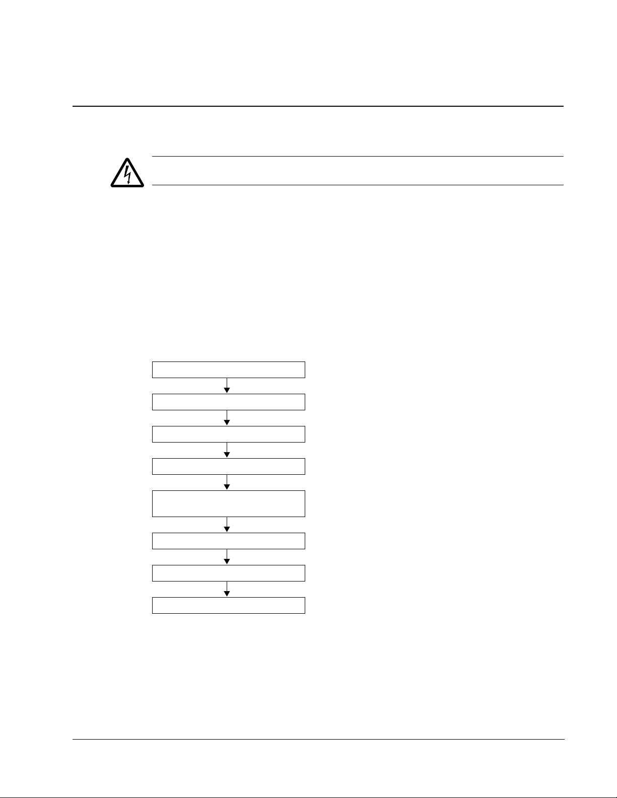
Installation flow chart
The installation of the ACQ550 adjustable speed AC drive follows the outline below.
The steps must be carried out in the order shown. At the right of each step are
references to the detailed information needed for the correct installation of the drive.
Task See
PREPARE for installation Preparing for installation on page 12
PREPARE the mounting location Prepare the mounting location on page 16
REMOVE the front cover Remove the front cover on page 17
MOUNT the drive Mount the drive on page 18
INSTALL wi ri n g Wiring overview on page 19 and
Install the wiring on page 26
CHECK installation Check installation on page 31
REINSTALL the cover Reinstall the cover on page 32
START-UP How to start up the drive on page 33
Installation
12 ACQ550-U1 User’s Manual
IP2040
Serial number
Type designation
Serial number
Type designation
Type designation
Serial number
Preparing for installation
Lifting the drive
Lift the drive only by the metal
chassis.
Unpacking the drive
1. Unpack the drive.
2. Check for any damage and
notify the shipper immediately
if damaged components are
found.
3. Check the contents against
the order and the shipping label to verify that all parts have been received.
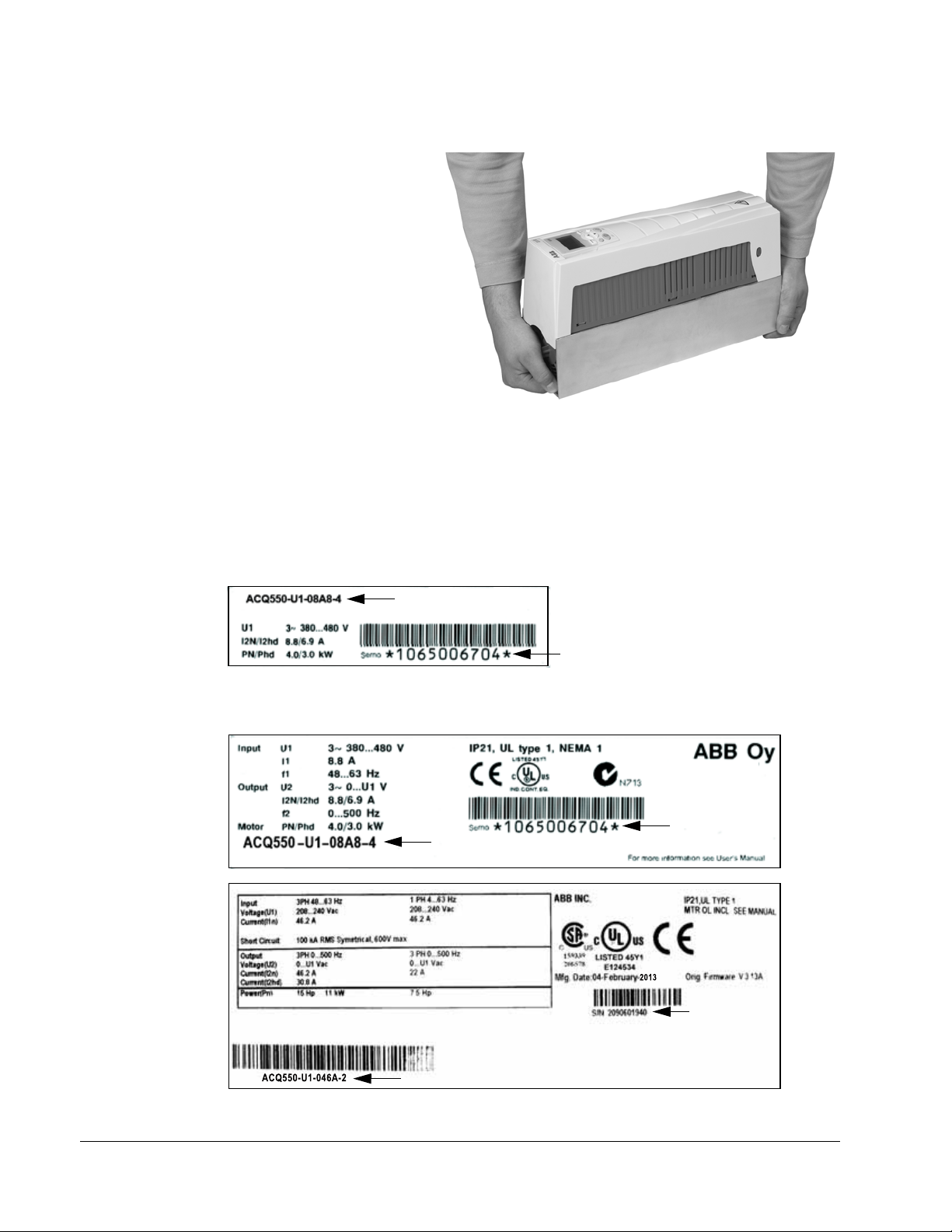
Drive identification
Drive labels
To determine the type of drive you are installing, refer to either:
• serial number label attached on upper part of the chokeplate between the
mounting holes, or
• type designation label attached on the heat sink – on the right side of the drive
cover. Two examples of the type designation label are given below.
Installation

ACQ550-U1 User’s Manual 13
AC, Standard Drive – 550 product series
Construction (region specific)
Output current rating
Voltage rating
Options
Examples of options:
B055 = IP54 / UL type 12 (no specification = IP21 / UL type 1).
0J400 = No control panel
L511 = OREL-01 Relay output extension
K451 = RDNA-01 DeviceNet
ACQ550-U1-08A8-4+J404+…
e.g. 08A8 = 8.8 A, see section Ratings on page 267 for details
2 = 208…240 V AC
4 = 380…480 V AC
6 = 500…600 VAC
U1= Setup and parts specific to US installation and NEMA compliance
Type designation
Use the following chart to interpret the type designation found on both the type
designation and the serial number label.
Ratings and frame size
The chart in section Ratings
the drive’s frame size – significant, since some instructions in this document vary,
depending on the drive’s frame size. To read the ratings tab le, you need the “Output
current rating” entry from the type designation. Also, when using the ratings table,
note that the table is broken into sections based on the drive’s “Voltage rating”.
Serial number
The format of the drive serial number shown on the labels is described below.
Serial number is of format CYYWWXXXXX, where
C: Country of manufacture
YY: Year of manufacture
WW: Week of manufacture; 01, 02, 03, … for week 1, week 2, week 3, …
XXXXX: Integer starting every week from 00001.
on page 267 lists technical specifications and identifies
Installation

14 ACQ550-U1 User’s Manual
Motor compatibility
The motor, drive and supply power must be compatible:
Motor
specification
Motor type 3-phase induction motor –
Nominal current Motor valu e is within this
Nominal frequency 10…500 Hz –
Voltage range Motor is compatible with
Insulation 500…600 V drives: Either
range: 0.2…2.0 · I
(I
2hd
current)
the ACQ550 voltage range.
the motor complies with
NEMA MG1 Part 31, or a
du/dt filter is used between
the motor and drive.
Verify Reference
• Type designation label on drive, entry for
= drive heavy duty
2hd
Output I
• Type designation on drive and rating table in
chapter Technical data on page 267.
208…240 V (for ACQ550-U1-XXXX-2) or
380…480 V (for ACQ550-U1-XXXX-4) or
500…600 V (for ACQ550-U1-XXXX-6)
For ACQ550-U1-XXXX-6
2hd
Tools required
To install the ACQ550 you need the following:
• screwdrivers (as appropriate for the mounting hardware used)
• wire stripper
• tape measure
, or
•drill
• for installations involving ACQ550-U1, frame sizes R5 or R6 and IP54 / UL type
12 enclosures: punch for creating conduit mounting holes
• for installations involving ACQ550-U1, frame size R6: appropriate crimping tool
for power cable lugs. See section Power terminal considerations – R6 frame size
on page 277.
• mounting hardware: screws or nuts and bolts, four each. The type of hardware
depends on the mounting surface and the frame size:
Frame size Mounting hardware
R1…R4 M5
R5 M6 1/4 in
R6 M8
#10
5/16 in
Suitable environment and enclosure
Confirm that the site meets the environmental requirements. To prevent damage
prior to installation, store and transport the drive according to the environmental
requirements specified for storage and transportation. See section Ambient
conditions
on page 296.
Installation

ACQ550-U1 User’s Manual 15
Confirm that the enclosure is appropriate, based on the site contamination level:
• IP21 / UL type 1 enclosure: The site must be free of airborne dust, corrosive
gases or liquids, and conductive contaminants such as dripping water,
condensation, carbon dust and metallic particles.
• IP54 / UL type 12 enclosure: This enclosure provides protection from airborne
dust and light sprays or splashing water from all directions.
• If, for some reason, an IP21 drive needs to be installed without the conduit box or
cover, or an IP54 drive without the conduit plate or hood, see the note in chapter
Technical data, page 300.
Suitable mounting location
Confirm that the mounting location meets the following constraints:
• The drive must be mounted vertically on a smooth, solid surface, and in a suitable
environment as defined above. For horizontal installation, contact your local ABB
representative for more information.
• The minimum space requirements for the drive are the outside dimensions (see
section Outside dimensions on page
(see section Cooling
on page 291).
294), plus air flow space around the drive
• The distance between the motor and the drive is limited by the maximum motor
cable length. See section Motor connection specifications
on page 279.
• The mounting site must support the drive’s modest weight. See section Weight on
page 295.
Installation
16 ACQ550-U1 User’s Manual
X0002
1
Installing the drive
WARNING! Before installing the ACQ550, ensure the input powe r supply to the drive
is off.
For flange mounting (mounting the drive in a cooling air duct), see the appropriate
Flange Mounting Instructions:
Frame
size
R1 FMK-A-R1 100000982 FMK-B-R1 100000990
R2 FMK-A-R2 100000984 FMK-B-R2 100000992
R3 FMK-A-R3 100000986 FMK-B-R3 100000994
R4 FMK-A-R4 100000988 FMK-B-R4 100000996
1
R5
1
R6
1
Not available in ACQ550-U1 IP54/UL type 12
AC8-FLNGMT-R5 ACS800-PNTG01U-EN - AC8-FLNGMT-R6 - -
IP21 / UL type 1 IP54 / UL type 12
Kit Code (English) Kit Code (English)
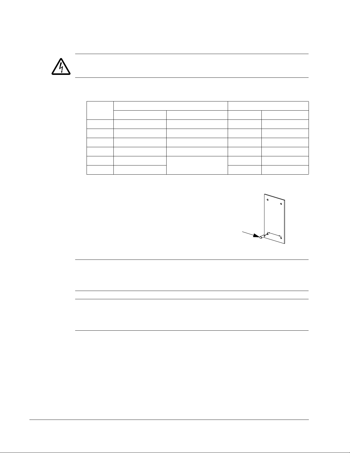
Prepare the mounting location
The ACQ550 should only be mounted where all of the
requirements defined in section Prepa ring for installation
on page 12 are met.
1. Mark the position of the mounting holes with the help of
the mounting template provided with the drive.
2. Drill the holes.
Note: Frame sizes R3 and R4 have four holes along the top. Use only two. If
possible, use the two outside holes (to allow room to remove the fan for
maintenance).
Note: ACS400 drives can be replaced using the original mounting holes. For R1 and
R2 frame sizes, the mounting holes are identical. For R3 and R4 frame sizes, the
inside mounting holes on the top of ACQ550 drives match ACS400 mounts.
Installation

ACQ550-U1 User’s Manual 17
3
IP2000
1
2
3
4
1
2
FM
R6
1
R1…R5
Remove the front cover
IP21 / UL type 1
1. Remove the control panel, if attached.
2. Loosen the captive screw at the top.
3. Pull near the top to remove the cover.
IP54 / UL type 12
1. If hood is present: Remove screws
(2) holding hood in place.
2. If hood is present: Slide hood up and
off of the cover.
3. Loosen the captive screws around
the edge of the cover.
4. Remove the cover.
Installation

18 ACQ550-U1 User’s Manual
IP2002
1
2
3
1, 4
FM
5
Mount the drive
IP21 / UL type 1
1. Position the ACQ550 onto the mounting screws or
bolts and securely tighten in all four corners.
Note: Lift the ACQ550 by its metal chassis (frame
size R6 by the lifting holes on both sides at the top).
2. Non-English speaking locations: Add a warning
sticker in the appropriate language over the existing
warning on the top of the module.
IP54 / UL type 12
For the IP54 / UL type 12 enclosures, rubber plugs are required in the holes
provided for access to the drive mounting slots.
1. As required for access, remove the rubber plugs.
Push plugs out from the back of the drive.
2. R5 & R6: Align the sheet metal hood (not shown) in
front of the drive’s top mounting holes. (Attach as
part of next step.)
3. Position the ACQ550 onto the mounting screws or
bolts and securely tighten in all four corners.
Note: Lift the ACQ550 by its metal chassis (frame
size R6 by the lifting holes on both sides at the top).
4. Reinstall the rubber plugs.
5. Non-English speaking locations: Add a warning sticker in the appropriate language
over the existing warning on the top of the module.
Installation

ACQ550-U1 User’s Manual 19
Wiring overview
Conduit/Gland kit
Wiring drives with the IP21 / UL type 1 enclosure requires a cond uit/gland kit with the
following items:
• conduit/gland box
• screws
• cover.
The kit is included with IP21 / UL type 1 enclosures.
Wiring requirements
WARNING! Ensure the motor is compatible for use with the ACQ550. The drive
must be installed by a competent person in accordance with the considerations
defined in section Preparing for installation on p age 12. If in doubt, contact you r local
ABB sales or service office.
As you install the wiring, observe the following:
• There are four sets of wiring instructions – one set for each combination of drive
enclosure type (IP21 / UL type and IP54 / UL type 12) and wiring type (conduit or
cable). Be sure to select the appropriate procedure.
• Determine electro-magnetic compliance (EMC) requirements per local codes.
See section Motor cable requirements for CE & C-Tick compliance on page 283.
In general:
– Follow local codes for cable size.
– Keep these four classes of wiring separated: input power wiring, motor wiring,
control/communications wiring and braking unit wiring.
• When installing input power and motor wiring, refer to the following, as
appropriate:
Terminal Description Specifications and notes
1
U1, V1, W1
PE Protective Ground Ground connections on page 275
U2, V2, W2 Power output to motor Motor connections on page 279
1
The ACQ550 -x1-xxxx-2 (208…240 V series) can be used with a single phase supply, if output
current is derated by 50%. For single phase supply voltage, connect power at U1 and W1.
3-phase power supply input Input power connections on page 271
• To locate input power and motor connection terminals, see section Power
connection diagrams on page 21. For specifications on power terminals, see
section Drive’s power connection terminals on page 276.
• For corner grounded TN systems, see section Corner grounded TN systems on
page 275.
• For IT systems, see section IT systems on page 276.
• For frame size R6, see section Power terminal considerations – R6 frame size on
page 277 to install the appropriate cable lugs.
Installation

20 ACQ550-U1 User’s Manual
• For drives using braking (optional), refer to the following, as appropriate:
Frame size Terminal Description Braking accessory
R1, R2 BRK+, BRK- Braking resistor Braking resistor. See section Brake
components on page 285.
R3, R4, R5, R6 UDC+, UDC- DC bus Contact your ABB representative to
order either:
• braking unit or
• chopper and resistor
• When installing control wiring, refer to the following chapters or sections, as
appropriate:
– Control terminals table on page 24
– Control connections
on page 289
– Application macros on page 57
– Complete parameter descriptions on page 83
– Embedded fieldbus on page 177
– Fieldbus adapter on page 229.
Installation

ACQ550-U1 User’s Manual 21
Panel connector
Fault LED (red)
Optional module 1
J2 – DIP switch
X1 – Communications
Optional module 2
GND
Power output to motor
Power input
EM1
X1 – Analog inputs and outputs
X1 – Digital inputs
X1 – Relay outputs
J2
ON
off position on position
for RS485 termination
(and 10 V ref. voltage output)
(and 24 V aux. voltage output)
PE
(U1, V1, W1)
(U2, V2, W2)
Optional braking
Frame
size
Terminal
labels
Brake options
R1, R2 BRK+, BRK- Brake resistor
R3, R4 UDC+, UDC- • Braking unit
• Chopper and resistor
(RS485)
R5/R6 differ.
See
Frame sizes
next page.
Diagram shows the R3 frame.
J2
ON
Other frames have similar layouts.
J1
AI1: (in voltage position)
AI2: (in current position)
ON
ON
J1 – DIP switches for analog inputs (two types can be used)
ON
12
J1
Power LED (green)
3AUA0000001571
EM3
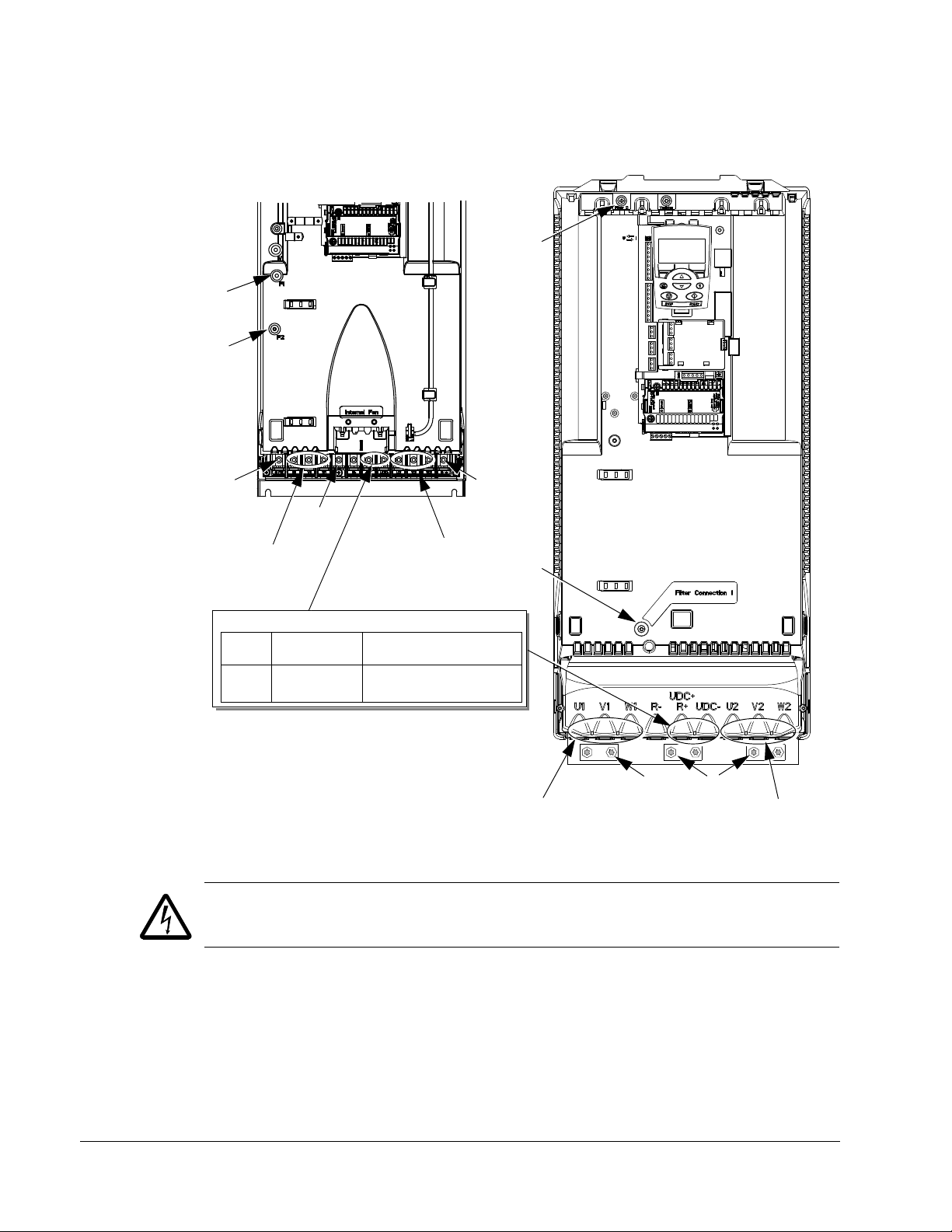
Power connection diagrams
The following diagram shows the terminal layout for frame size R3, which, in
general, applies to frame sizes R1
terminals.
…R6, except for the R5/R6 power and ground
WARNING! To avoid danger, or damage to the drive, on IT systems and corner
grounded TN systems, see section Disconnecting the internal EMC filte r on page 23.
Installation
22 ACQ550-U1 User’s Manual
GND
Power input
PE
(U1, V1, W1)
Optional braking
Frame
size
Terminal
labels
Brake options
R5, R6 UDC+, UDC- • Braking unit
• Chopper and resistor
X0011
F2
Power input
PE
(U1, V1, W1)
F1
F2
X0013
Power output to motor
(U2, V2, W2)
R5 R6
GND
GND
Power output to motor
(U2, V2, W2)
F1
The following diagram shows the power and ground terminal layout for frame sizes
R5 and R6.
WARNING! To avoid danger, or damage to the drive, on IT systems and corner
grounded TN systems, see section Disconnecting the internal EMC filter on p ag e 23.
Installation
ACQ550-U1 User’s Manual 23
Disconnecting the internal EMC filter
On certain types of systems, you must disconnect the internal EMC filter, otherwise
the system will be connected to ground potential through the EMC filter capacitors,
which might cause danger, or damage the drive.
Note: When the internal EMC filter is disconnected, the drive is not EMC compa tible.
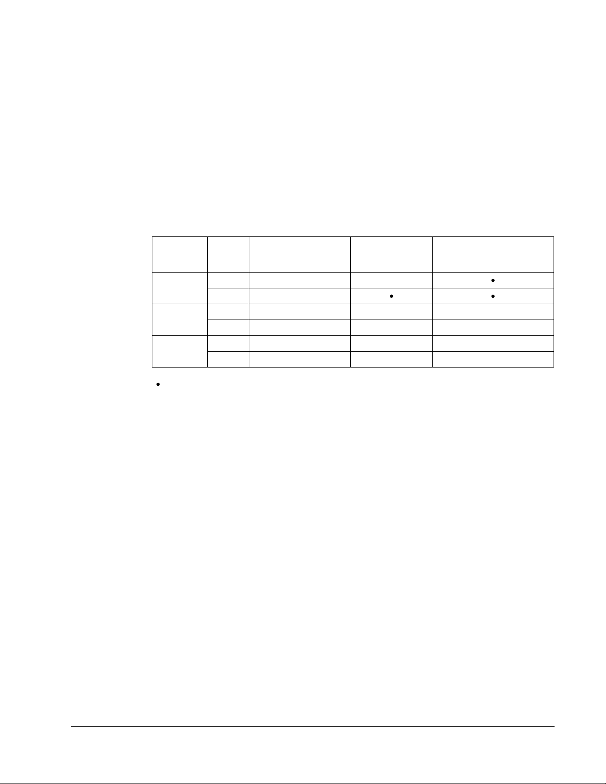
The following table shows the installation rules for the EMC filter screws in order to
connect or disconnect the filter, depending on the system type and the frame size.
For more information on the different system types, see IT sy stems on page 276 and
Corner grounded TN systems on page 275.
The locations of screws EM1 and EM3 are shown in the diagram on page 21. The
locations of screws F1 and F2 are shown in the diagram on page 22.
Frame
sizes
R1…R3
R4
R5…R6
x = Install the screw. (EMC filter will be connected.)
= Replace the screw with the provided polyamide screw. (EMC filter will be disconnected.)
–
= Remove the screw. (EMC filter will be disconnected.)
1
ACQ550-U1 drives are shipped with screw EM3 already removed.
Screw
EM1 x x
1
EM3
EM1 x x –
1
EM3
F1 x x –
F2 x x –
Symmetrically
grounded TN systems
(TN-S systems)
x
x ––
Corner grounded
TN systems
IT systems (ungrounded
or high-resistance-
grounded [> 30 ohm])
Installation
24 ACQ550-U1 User’s Manual
Analog I/O
ON
1
ON
ON
1
ON
ON
1
ON
ON
1
ON
Digital inputs
1
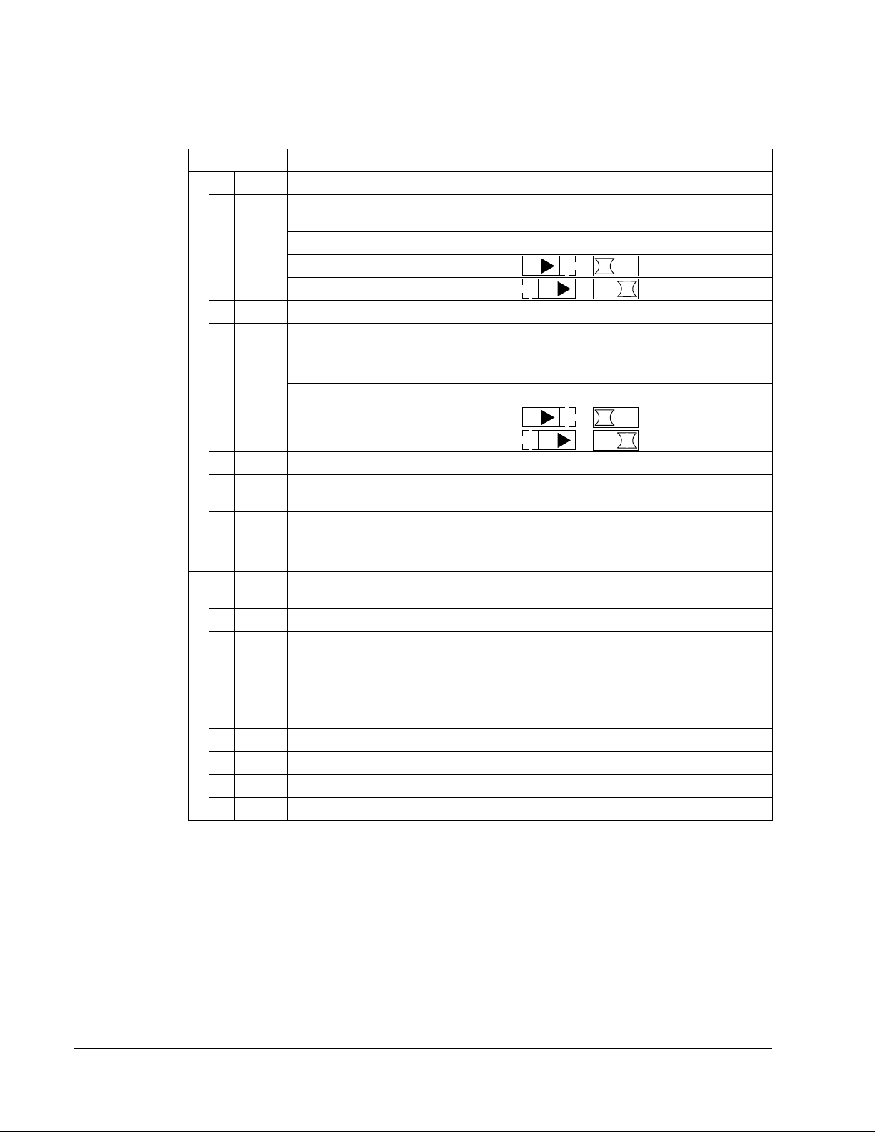
Control terminals table
The following provides information for connecting control wiring at X1 on the drive.
X1 Hardware description
1 SCR Terminal for signal cable shield (screen). (Connected internally to chassis ground.)
2 AI1 Analog input channel 1, programmable. Default2= frequency reference. Resolution
0.1%, accuracy ±1%.
Two different DIP switch types can be used.
J1: AI1 OFF: 0…10 V (R
J1: AI1 ON: 0…20 mA (Ri= 100 ohm)
3 AGND Analog input circuit common (connected internally to chassis gnd. through 1 Mohm).
4 +10 V Potentiometer reference source: 10 V ±2%, max. 10 mA (1 kohm <
5 AI2 Analog input channel 2, programmable. Default2= not used. Resolution 0.1%,
accuracy ±1%.
Two different DIP switch types can be used.
J1: AI2 OFF: 0…10 V (R
J1: AI2 ON: 0…20 mA (R
6 AGND Analog input circuit common (connected internally to chassis gnd. through 1 Mohm).
7 AO1 Analog output, programmable. Default2= frequency. 0…20 mA (load < 500 ohm).
Accuracy ±3%.
8 AO2 Analog output, programmable. Default
Accuracy ±3%.
9 AGND Analog output circuit common (connected internally to chassis gnd. through 1 Mohm).
10 +24V Auxiliary voltage output 24 V DC / 250 mA (reference to GND), short circuit
protected.
11 GND Auxiliary voltage output common (connected interna lly as floating).
12 DCOM Digital input common. To activate a digital input, there must be 10 V
(or -10 V) betwee n that input and DCOM. The 24 V may be provided by the
ACQ550 (X1-10) or by an external 12…24 V source of either polarity.
13 DI1 Digital input 1, programmable. Default
14 DI2 Digital input 2, programmable. Default2=fwd/rev.
15 DI3 Digital input 3, programmable. Default
16 DI4 Digital input 4, programmable. Default2= constant speed sel (code).
17 DI5 Digital input 5, programmable. Default
18 DI6 Digital input 6, programmable. Default
= 312 kohm)
i
= 312 kohm)
i
= 100 ohm)
i
R < 10 kohm).
2
= current. 0…20 mA (load < 500 ohm).
2
= start/stop.
2
= constant speed sel (code).
2
= ramp pair selection (code).
2
= not used.
Installation
ACQ550-U1 User’s Manual 25
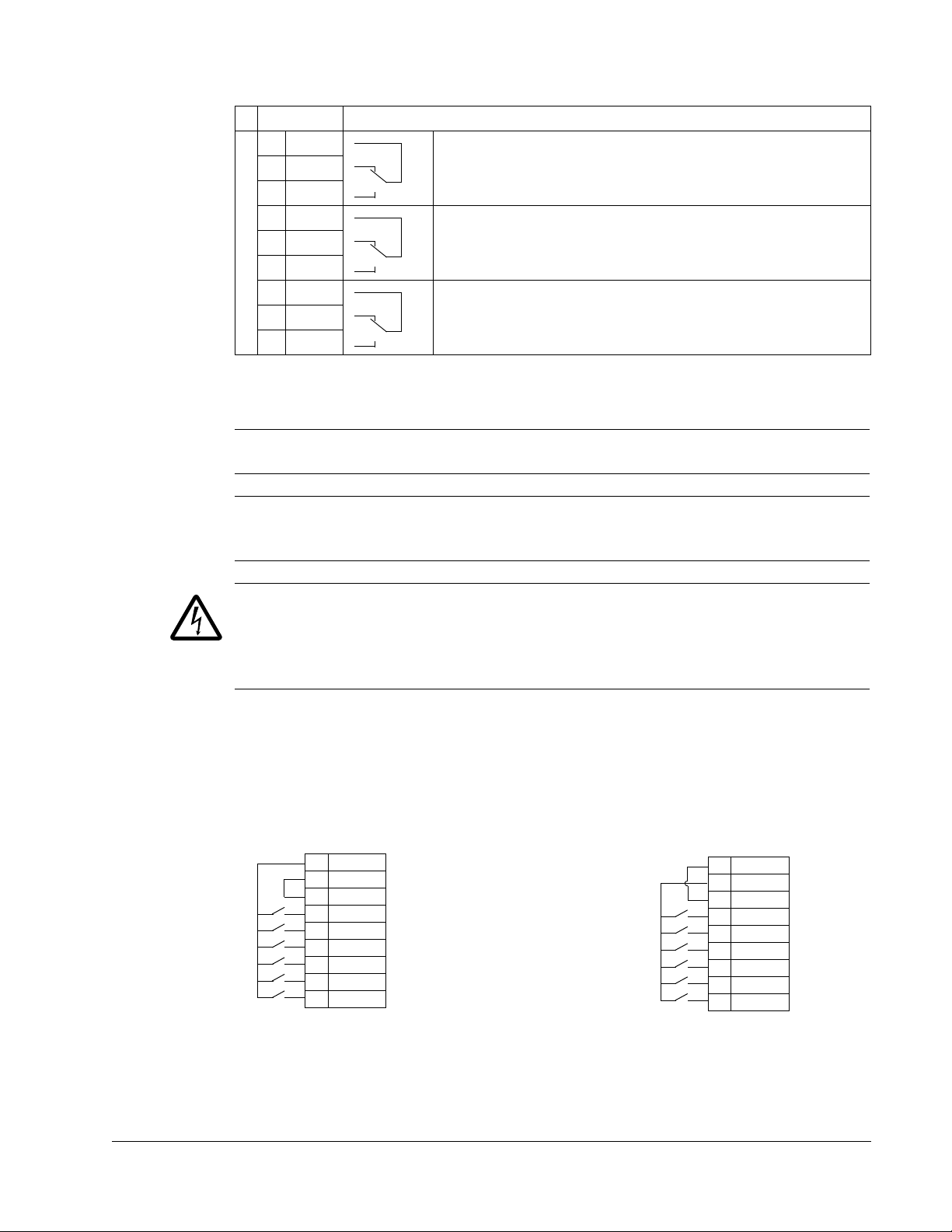
Relay outputs
NPN connection (sink)PNP connection (source)
10 +24V
11 GND
12 DCOM
13 DI1
14 DI2
15 DI3
16 DI4
17 DI5
18 DI6
10 +24V
11 GND
12 DCOM
13 DI1
14 DI2
15 DI3
16 DI4
17 DI5
18 DI6
X1
X1
X1 Hardware description
19 RO1C Relay output 1, programmable. Default2= Ready
20 RO1A
21 RO1B
22 RO2C Relay output 2, programmable. Default
23 RO2A
24 RO2B
25 RO3C Relay output 3, programmable. Default
26 RO3A
27 RO3B
1
Digital input impedance 1.5 kohm. Maximum voltage for digital inputs is 30 V .
2
Default values depend on the macro used. Values specified are for the default macro. See chapter
Application macros on page 57.
Maximum: 250 VAC / 30 V DC, 2 A
Minimum: 500 mW (12 V, 10 mA)
Maximum: 250 VAC / 30 V DC, 2 A
Minimum: 500 mW (12 V, 10 mA)
Maximum: 250 VAC / 30 V DC, 2 A
Minimum: 500 mW (12 V, 10 mA)
2
= Running
2
= Fault (-1)
Note: Terminals 3, 6 and 9 are at the same potential.
Note: For safety reasons the fault relay signals a “fault” when the ACQ550 is
powered down.
WARNING! All ELV (Extra Low V oltage) circuits connected to the drive must be used
within a zone of equipotential bonding, i.e. within a zone where all simultaneously
accessible conductive parts are electrically connected to prevent hazardous voltages
appearing between them. This is accomplished by a proper factory grounding.
The terminals on the control board as well as on the optional modules attachable to
the board fulfil the Protective Extra Low Voltage (PELV) requirements stated in
EN 50178, provided that the external circuits connected to the terminals also fulfil
the requirements and the installation site is below 2000 m (6562 ft).
You can wire the digital input terminals in either a PNP or NPN configuration.
Installation

26 ACQ550-U1 User’s Manual
ohm
M
3~
U1
V1
W1
PE
Install the wiring
Checking motor and motor cable insulation
WARNING! Check the motor and motor cable insulation before connecting the drive
to input power. For this test, make sure that motor cables are NOT connected to the
drive.
1. Complete motor cable connections to the motor, but NOT to the drive output
terminals (U2, V2, W2).
2. Measure the insulation resistance between each
phase conductor and the Protective Earth conductor
using a measuring voltage of 500 V DC. The
insulation resistance of an ABB motor must exceed
10 Mohm (reference value at 25 °C or 77 °F). For the
insulation resistance of other motors, please consult
the manufacturer’s instructions. Note: Moisture inside the motor casing will reduce
the insulation resistance. If moisture is suspected, dry the motor and repeat the
measurement.
Installation
ACQ550-U1 User’s Manual 27
1
2
X0004
6
3
IP2001
6
7
4
8
8
X0005
Frame
size
Tightening torque
N·m
lb·ft
R1, R2 1.4
1
R3 2.5
1.8
R4 5.6; PE: 2
4; PE 1.5
R5 15
11
R6 40; PE: 8
30; PE: 6
9
X0006
12
IP2003
11
13
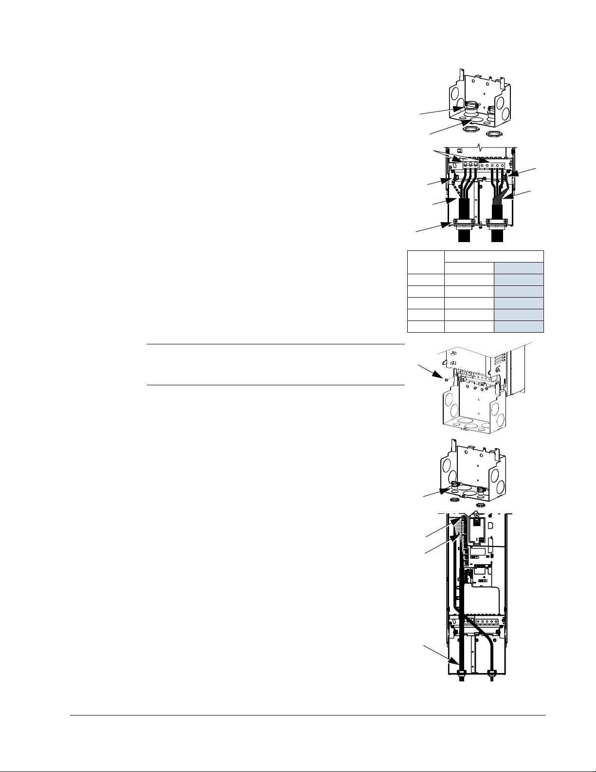
Wiring IP21 / UL type 1 enclosure with cables
1. Open the appropriate knockouts in the conduit/gland
box. (See section Conduit/Gland kit on page 19.)
2. Install the cable clamps for the power/motor cables.
3. On the input power cable, strip the sheathing back far
enough to route individual wires.
4. On the motor cable, strip the sheathing back far
enough to expose the copper wire shield so that the
shield can be twisted into a bundle (pig-tail). Keep the
bundle not longer than five times its width to minimize
noise radiation.
360° grounding under the clamp is recommended for
the motor cable to minimize noise radiation. In this
case, remove the sheathing at the cable clamp.
5. Route both cables through the clamps.
6. Strip and connect the power/motor wires and the
power ground wire to the drive terminals. See the
table on the right for tightening torques.
Note: For R6 frame size, refer to section Power
terminal considerations – R6 frame size on page 277.
7. Connect the bundle (pig-tail) created from the motor
cable shield to the GND terminal.
8. Install conduit/gland box and tighten the cable clamps.
9. Install the cable clamp(s) for the control cable(s).
(Power/motor cables and clamps not shown in the
figure.)
10. Strip control cable sheathing and twist the copper
shield into a bundle (pig-tail).
11. Route control cable(s) through clamp(s) and tighten
clamp(s).
12. Connect the ground shield bundle (pig-tail) for digital and
analog I/O cables at X1-1. (Ground only at the drive end.)
13. Strip and connect the individual control wires to the
drive terminals. See section Control terminals table
on page 24. Use a tightening torque of 0.4 N·m
(0.3 lb·ft).
14. Install the conduit/gland box cover (1 screw).
Installation

28 ACQ550-U1 User’s Manual
2
X0007
3
X0005
4
IP2004
7
7
5
Frame
size
Tightening torque
N·m lb·ft
R1, R2 1.4
1
R3 2.5
1.8
R4 5.6; PE: 2
4; PE 1.5
R5 15
11
R6 40; PE: 8
30; PE: 6
10
8
IP2005
11
Wiring IP21 / UL type 1 enclosure with conduit
1. Open the appropriate knockouts in the conduit/gland
box. (See section Conduit/Gland kit on page 19.)
2. Install thin-wall conduit clamps (not supplied).
3. Install conduit/gland box.
4. Connect conduit runs to box.
5. Route input power and motor wiring through
conduits (must be separate conduit runs).
6. Strip wires.
7. Connect power, mot or and ground wires to the drive
terminals. See the table on the right for tightening
torques.
Note: For R6 frame size, refer to section Power
terminal considerations – R6 frame size on page
277.
8. Route the control cable through the conduit (must be
separate from input power and motor conduit runs).
9. Strip the control cable sh eathing and twist the copper
shield into a bundle (pig-tail).
10. Connect the ground shield bundle (pig-tail) for digital
and analog I/O cables at X1-1. (Ground only at the
drive end.)
11. Strip and connect the individual control wires to the
drive terminals. See section Control terminals table
on page 24. Use a tightening torque of 0.4 N·m
(0.3 lb·ft).
Installation
12. Install the conduit/gland box cover (1 screw).
ACQ550-U1 User’s Manual 29
1
IP5003
4
5
2
IP5004
3
4
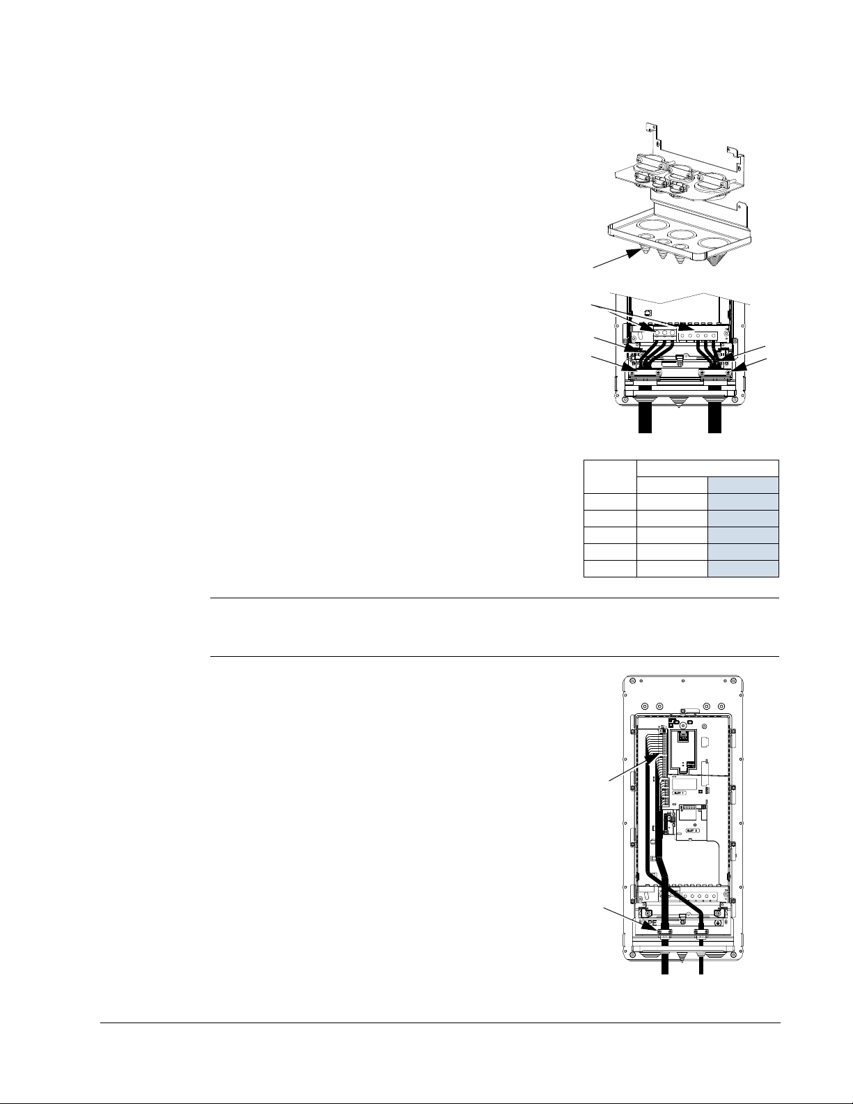
Frame
size
Tightening torque
N·m
lb·ft
R1, R2 1.4
1
R3 2.5
1.8
R4 5.6; PE: 2
4; PE 1.5
R5 15
11
R6 40; PE: 8
30; PE: 6
8
IP5005
9, 10
Wiring IP54 / UL type 12 enclosure with cables
1. Cut the cable seals as needed for the power, motor
and control cables. The cable seals are coneshaped, rubber seals on the bottom of the drive.
The conical part of the seals must face downwards
when the seals are inserted in the lead-through
plate holes.
2. On the input power cable, strip the sheathing back
far enough to route individual wires.
3. On the motor cable, strip the sheathing back far
enough to expose the copper wire shield so that
the shield can be twisted into a bundle (pig-tail).
Keep the bundle not longer than five times its width
to minimize noise radiation.
360° grounding under the clamp is recommended
for the motor cable to minimize noise radiation. In
this case, remove the sheathing at the cable
clamp.
4. Route both cables through the clamps and tighten
the clamps.
5. Strip and connect the power/motor wires and the
power ground wire to the drive terminals. See the
table on the right for tightening torques.
Note: For R6 frame size, refer to section Power terminal considerations – R6 frame
size on page 277.
6. Connect the bundle (pig-tail) created from the
motor cable shield to the GND terminal.
7. Strip control cable sheathing and twist the copper
shield into a bundle (pig-tail).
8. Route control cable(s) through clamp(s) and
tighten clamp(s).
9. Connect the ground shield bundle (pig-tail) for
digital and analog I/O cables at X1-1. (Ground only
at the drive end.)
10. Strip and connect the individual control wires to the
drive terminals. See section Control terminals table
on page 24. Use a tightening torque of 0.4 N·m
(0.3 lb·ft).
Installation

30 ACQ550-U1 User’s Manual
IP5013
1
2
IP5016
3
IP5007
6
4
Frame
size
Tightening torque
N·m
lb·ft
R1, R2 1.4
1
R3 2.5
1.8
R4 5.6; PE: 2
4; PE 1.5
R5 15
11
R6 40; PE: 8
30; PE: 6
Wiring IP54 / UL type 12 enclosure with conduit
1. Remove and discard the cable seals where conduit
will be installed. (The cable seals are cone-shaped,
rubber seals on the bottom of the drive.)
2. For each conduit run, install water tight conduit
connectors (not supplied).
3. Route the power wiring through the conduit.
4. Route the motor wiring through the conduit.
5. Strip the wires.
6. Connect the power, motor and ground wires to the
drive terminals. See the table on the right for
tightening torques.
Note: For R6 frame size, refer to section Power
terminal considerations – R6 frame size on page
277.
7. Route the control cable through the conduit.
8. Strip the control cable sheathing and twist the
copper shield into a bundle (pig-tail).
9. Connect the ground shield bundle (pig-tail) for digital and analog I/O ca bles at X1-1.
(Ground only at the drive end.)
10. Strip and connect the individual control wires to the drive terminals. See section
Control terminals table on page 24. Use a tightening torque of 0.4 N·m (0.3 lb·ft).
Installation
 Loading...