


Softstarters Type PSTX30...PSTX1250 User Manual short form
<![endif]>1SFC132082M9901

 according to EN /IEC 60947-4-2
This manual belongs to:
___________________________________________________________
2 Softstarters Type PSTX30...PSTX1250 User Manual short form 1SFC132082M9901
English |
ABB softstarter PSTX30...PSTX1250 operating instructions |
Page 4 |
||||||||||||||
EN |
Graphics |
|
|
|
|
|
|
|
Page 244 |
|||||||
|
|
|
|
|
|
|
|
|
|
|
|
|
|
|
|
|
Svenska |
ABB mjukstartare PSTX30...PSTX1250 bruksanvisning |
Sida 20 |
||||||||||||||
SV |
Grafik |
|
|
|
|
|
|
|
|
|
|
Sida 244 |
||||
|
|
|
|
|
|
|
|
|
|
|
|
|
|
|
|
|
Deutsch |
ABB sanftanlasser PSTX30...1250 betriebsanleitung |
Seite 36 |
||||||||||||||
DE |
Grafiken |
|
|
|
|
|
|
|
|
Seite 244 |
||||||
|
|
|
|
|
|
|
|
|
|
|
|
|
|
|
|
|
Français |
ABB démarrreur progressif PSTX30...PSTX1250 instruction de |
Page 52 |
||||||||||||||
FR |
service |
Page 244 |
||||||||||||||
|
Graphiques |
|
|
|
|
|
|
|||||||||
|
|
|
|
|
|
|
|
|
|
|
|
|
|
|
|
|
Italiano |
ABB avviatore graduale PSTX30...PSTX1250 instruzioni operative |
Pagina 68 |
||||||||||||||
IT |
Grafiche |
|
|
|
|
|
|
|
Pagina 244 |
|||||||
|
|
|
|
|
|
|
|
|
|
|
|
|
|
|
|
|
Español |
ABB arrancadores suaves PSTX30...PSTX1250 instrucciones de uso |
Página 84 |
||||||||||||||
ES |
Gráficos |
|
|
|
|
|
|
|
Página 244 |
|||||||
|
|
|
|
|
|
|
|
|
|
|
|
|
|
|
|
|
Portu- |
ABB chave de partida suave PSTX30...PSTX1250 Instruções de |
Página 100 |
||||||||||||||
gues |
Serviço |
Página 244 |
||||||||||||||
PT |
Gráficos |
|
|
|
|
|
|
|
|
|
||||||
|
|
|
|
|
|
|
|
|
|
|
|
|
|
|
|
|
Neder- |
ABB softstarter PSTX30...PSTX1250 Gebruiksaanwijzing |
Pagina 116 |
||||||||||||||
lands |
Grafieken |
|
|
|
|
|
|
Pagina 244 |
||||||||
NL |
|
|
|
|
|
|
|
|
|
|
|
|
|
|
|
|
|
|
|
|
|
|
|
|
|
|
|
|
|
|
|
|
|
Polski |
Softstarter ABB PSTX30...PSTX1250 – instrukcja obsługi |
Strona 132 |
||||||||||||||
PL |
Rysunki |
|
|
|
|
|
|
|
|
Strona 244 |
||||||
|
|
|
|
|
|
|
|
|
|
|
|
|
|
|
|
|
Русский |
Краткая инструкция по эксплуатации устройств плавного пускаABB |
стр. 148 |
||||||||||||||
RU |
PSTX30...PSTX1250 |
|
||||||||||||||
|
Иллюстрации |
|
|
|
|
стр. 244 |
||||||||||
|
|
|
|
|
|
|
|
|
|
|
|
|
|
|
|
|
Suomi |
ABB:n pehmokäynnistinten PSTX30...PSTX1250 käyttöohjeet |
Sivu 164 |
||||||||||||||
FI |
Graafiset symbolit |
|
|
Sivu 244 |
||||||||||||
|
|
|
|
|
|
|
|
|
|
|
|
|
|
|
|
|
Türkçe |
ABB Yumuşak Yolvericiler - PSTX30...PSTX1250 Kullanım Talimatları |
Sayfa 180 |
||||||||||||||
TR |
Grafikler |
|
|
|
|
|
|
|
|
|
Sayfa 244 |
|||||
|
|
|
|
|
|
|
|
|
|
|
|
|
|
|
|
|
|
|
|
|
|
|
|
|
|
|
|
|
|
|
|
|
196-244 |
|
|
|
|
|
|
|
|
|
|
|
|
|
|
|
|
|
|
ABB PSTX30...PSTX1250 |
212 |
||||||||||||||
|
|
|
|
|
|
|
|
|
|
|
|
|
|
|
|
244 |
|
|
|
|
|
|
|
|
|
|
|
|
|
|
|
|
|
Čeština |
ABB softstartéry PSTX30...PSTX1250 příručka |
Strana 228 |
||||||||||||||
CS |
grafika |
|
|
|
Strana 244 |
|||||||||||
|
|
|
|
|
|
|
|
|
|
|
||||||
|
|
|
|
|
|
|
|
|
|
|
|
|
|
|
|
|
|
Graphics |
244 |
||||||||||||||
|
|
|
|
|
|
|
|
|
|
|
|
|
|
|
|
|
<![endif]>CS ZH AR TR FI RU PL NL PT ES IT FR DE SV EN
Softstarters Type PSTX30...PSTX1250 User Manual short form 1SFC132082M9901 3
<![endif]>EN
1 Read this first
Thank you for selecting this ABB PSTX softstarter. Read carefully and make sure you understand all instructions before you mount, connect and configure the softstarter.
This manual is a short form manual intended for quick and easy installation of the PSTX softstarter. For complete information, see 1SFC132081M0201 - Softstarters Type PSTX30...PSTX1250,
•The softstarter shall be installed by authorized personnel only.
•ABB personnel must obey the ABB CISE 15.4 instructions.
•This manual is a part of the PSTX softstarter and must always be available to personnel that works with this material.
•Always read the full manual before you use the softstarter.
In the User Manual, these symbols are used:
Warning
General warning symbol indicates the presence of a hazard which could result in personal injury and damage to equipment or property.
Warning
Warning symbol indicates the presence of hazardous voltage which could result in personal injury.
Warning
Symbol indicates that only authorized and appropriately trained personnel are allowed to do the installation, operation and maintenance of the product. It should be done in accordance with existing laws and regulations.
Information
Information sign tells the reader important facts and conditions.
The graphics symbol in the right margin: refers to graphical information.
Approved personnel are allowed to install and make the electrical connection of the softstarter in accordance with existing laws and regulations.
Examine the softstarter and the package when you unpack your new PSTX softstarter. If there are damages, please speak to the transportation company or the ABB reseller/ office immediately.
Only approved personnel are allowed to do service and repair.
Note: not approved repair can effect the warranty.
Modifications to data in this manual can be applied without notice.
4 Softstarters Type PSTX30...PSTX1250 User Manual short form 1SFC132082M9901
2 Description
The PSTX softstarter has the latest technology for soft starting and soft stopping of standard squirrel cage motors.
General data |
Description |
|
|
Rated insulation voltage, Ui |
600 V / 690 V |
|
|
Rated operational voltage, Ue |
208-600 / 690 V, 50 / 60 Hz |
|
|
Rated control supply voltage, Us |
100-250 V, 50 / 60 Hz |
|
|
Voltage tolerance |
+10% to -15% |
|
|
Frequency tolerance |
± 10% |
|
|
Rated impulse withstand voltage |
6 kV operational circuit / 4 kV control supply circuit |
|
|
Inputs |
Start, stop, 3 programmable inputs, temperature |
|
sensor input |
|
|
24 V output |
24 V DC ± 5% Max 250 mA |
|
|
Analog output |
4-20 mA, 0-20 mA, 0-10 V, 0-10 mA |
|
|
Relay outputs |
3 programmable |
|
|
Communication |
3 Fieldbus ports, Extension I/O |
|
|
EMC |
IEC 60947-4-2 Class A 1 |
Recommended fuse |
6 A Delayed |
Control supply circuit |
MCB use C characteristics |
|
|
Pollution degree |
3 |
|
|
1 This product has been designed for environment A. Use of this product in environment B may cause unwanted electromagnetic disturbances in which case the user may be required to taken adequate mitigation measures.
 For more detailed electrical data and specifications, see
1SFC132081M0201 - Softstarters Type PSTX30...PSTX1250, Installation and Commissioning Manual
Suitable For Use On A Circuit Capable Of Delivering Not More Than
____ Symmetrical Amperes, ___ Volts Maximum When Protected by  15
15
___ J Class Time Delay Fuses or RK5 class Fuses or circuit breaker.
Refer to table 8.1 for corresponding current and voltage level for any given device.
The product should only be used within the specified ratings. Be aware
of the ambient temperature and altitude above sea level. Derating is  01 required above 40 °C (104 °F) and above 1000 m (3281 ft).
For more details, see 1SFC132081M0201 - Softstarters Type PSTX30...
PSTX1250, Installation and Commissioning Manual available
<![endif]>EN
Softstarters Type PSTX30...PSTX1250 User Manual short form 1SFC132082M9901 5
|
3 Mounting |
|
| <![if ! IE]> <![endif]>EN |
||
The PSTX softstarters has different sizes that you can install with M6 |
||
|
||
|
bolts, or bolts with the same dimension and strength. |
1.Find the correct drawing with dimensions for your softstarter and make sure that you have the correct drilling plan. Drilling plan is also printed on the box.
2.If the softstarter is installed in an enclosure, make sure that the enclosure size is not smaller than the minimum recommended.
Select the size from the applicable table for IEC or .
.
3.Make sure that the distance to the wall and the front, and the installation angle meet the requirements.
4.Make sure that there is free flow of air through the product.
5.You can remove the HMI and use it as a remote control. Drill a hole where you want to install the HMI. Use RJ45 cable between the HMI and the softstarter. The maximum cable length is 3 m.
Roll together the remaining cable to prevent blockage of the door.
Use the provided cable or another non shielded RJ45 cable.
Shielded cables should not be used.
Risk of damage to property. Make sure that no liquids, dust or conductive parts can go into the softstarter.
If you do not obey these instructions, this can cause the softstarter to become overheated or not operate correctly.

 02
02

 03
03

 04
04
 05
05 
 06
06
6 Softstarters Type PSTX30...PSTX1250 User Manual short form 1SFC132082M9901
4 Connection
This product is carefully manufactured and tested but there is a risk that damage can occur from such as shipment and incorrect operation. Obey to the procedure below during initial installation:
<![endif]>EN
Hazardous voltage: Will cause death or serious injury. Turn off and lock out all power that supply this device before you start work on the
equipment.
Mounting and electrical connection of the softstarter must be made by authorized personnel and in accordance with existing laws and regulations.
Apply the control supply voltage to make sure that the by-pass relays are in open position before you connect the softstarters PSTX30...
PSTX170 to operational voltage for the first time. If not, the equipment can start accidentally.
ABB personnel must obey to the ABB CISE 15.4 instructions.
1. |
To mount the softstarter, refer to Chapter 3 “Mounting”. |
|
|
2. |
Connect the main circuit: terminals 1L1 - 3L2 - 5L3 to the line side and |
|
|
|
terminals 2T1 - 4T2 - 6T3 to the motor side. Use wire connection for |
|
|
|
|
07 |
|
|
PSTX30...105, see Figure 1 in graphics 7, and terminal connection for |
|
|
|
|
|
|
|
PSTX142...1250, see Figure 2 , in graphics 7. |
|
|
|
|
|
|
|
PSTX softstarters can be connected both “In Line” and “Inside |
|
|
|
Delta” see figure 1. |
|
|
Use only wires of same dimension when you connect 2 wires on each terminal. (PSTX30...105 only).
1
PSTX PSTX
<![endif]>1SFC132082M9901
Figure 1: In Line, Inside Delta
Softstarters Type PSTX30...PSTX1250 User Manual short form 1SFC132082M9901 7
<![endif]>EN
Capacitors for power factor compensation are not allowed between the softstarter and the motor, since this can cause current peaks which can damage the thyristors in the softstarter. If you use such capacitors, they must be connected on the line side of the softstarter.
3. |
Connect control supply voltage to terminals 1 and 2. |
|
08 |
||
|
|
|
|
|
|
4. |
Connect terminal 22 to the functional earth. |
|
|
||
|
09 |
||||
|
|
|
|
|
|
|
|
|
|
|
|
The earthing is not a protective earth, it is a functional earth.
The earthing cable must be as short as possible. Maximum length 0.5 m. The earthing cable must be connected to the mounting plate, which must also be earthed.
5. Look at the diagram and connect the start/stop circuits: terminal 13, |
|
10 |
||
14, 18, 19 and 20/21, with the internal 24V DC terminal. When using |
|
|||
internal 24 V DC (terminals 20 or 21), the terminals 18 and 19 should |
|
|
||
be connected to each other. |
|
|
||
|
|
|
|
|
|
|
|
|
|
Terminal 15, 16 and 17 are programmable inputs for purposes such as reset, slow speed forward, slow speed reverse, stand still brake etc.
For usage of external supply see 1SFC132081M0201 - Softstarters
Type PSTX30...PSTX1250, Installation and Commissioning Manual
Use 24V DC only when you connect terminal 13, 14, 15, 16 and 17. Other voltages can cause damage to the softstarter and the warranty will no longer be valid.
6. Connect terminals 4, 5, 6, 7, 8, 9, 10, 11 and 12 to use the signal |
|
11 |
output relays. These are potential free contacts for maximum 250 V |
|
|
AC, 1.5 A AC-15 and 30 V DC, 5 A DC-12. |
|
|
7.Check that the operational voltage and control supply voltage correspond to the softstarter ratings.
8.Switch ON the control supply voltage, terminals 1 and 2.
9.Configure applicable parameters given in chapter 6,
Softstarter settings.
8 Softstarters Type PSTX30...PSTX1250 User Manual short form 1SFC132082M9901
10. Switch the operational voltage to ON. |
|
|
|
|
|
You can be flexible when you connect the PSTX softstarter, |
|
12 |
but following the previous steps will enable operation of the PSTX |
|
|
softstarter. You can find an example of a full installation in the graphics |
|
|
section. The first one uses fuses and contactors and the second one |
|
|
uses a circuit breaker. |
|
|
Refer to the timing diagram graphics 13 for the basic behaviour of |
|
|
|
13 |
|
PSTX softstarter. |
|
Built in Modbus RTU
The PSTX softstarter has an RS485 physical interface (terminals 23 and 24), that can be connected to external devices which have support for RS485 based communication. Through this interface it is possible to control the softstarter, retrieve status information and upload and download parameters. The softstarter has a Modbus RTU slave implemented via the RS485 interface.
See Figure 1.
PTC/PT100 temperature sensor input
The softstarter has input terminals for PTC and PT100 elements (terminals 25, 26 and 27). Please note that both PTC and PT100 cannot be used at the same time. See Figure 1.
Analogue output
The softstarter has one output for a configurable analog output signal (terminals 29 and 30). The load resistance is maximum 500 ohm for current output and minimum 500 ohm for voltage output. See Figure 1.
<![endif]>EN
1
Com 3 |
|
Temp In |
|
|
Analog out |
||||||
+(B) -(A) |
T1 |
T2 T3 |
+24V + GND |
||||||||
|
|
|
|
|
|
|
|
|
|
|
|
23 24 25 26 27 28 29 30
<![endif]>1SFC132082M9901
Figure 1: Terminal connection
For instructions and programming see
1SFC132081M0201 - Softstarters Type PSTX30...PSTX1250, Installation and Commissioning Manual
Softstarters Type PSTX30...PSTX1250 User Manual short form 1SFC132082M9901 9
<![endif]>EN
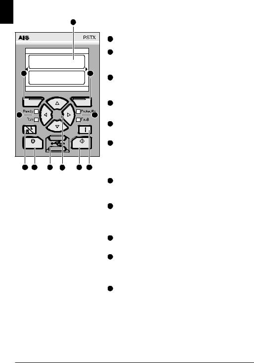
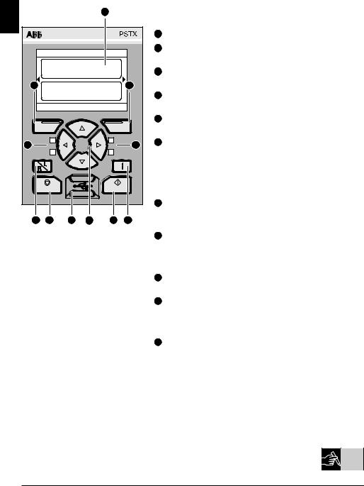
5 Human machine interface (HMI)
|
|
|
|
A |
|
|
Refer to figure 1 for the HMI parts: |
|
|
|
|
|
|
|
|
|
|
|
|
|
|
|
|
|
A |
Display for information. |
|
Local |
PSTX30 |
|
|
|
B |
Left selection soft key. The function is |
|
|
|
|
|
|
|
|||
|
Motor current |
0.0 |
A |
|
|
|
showed to the left in the display above the |
|
|
|
|
|
|
|
|
key. |
|
B |
Motor current |
0.0 |
% |
C |
|
C |
Right selection soft key. The function is |
|
|
|
|
|
|
|
|||
|
|
|
|
|
|
|
|
showed to the right in the display above the |
|
Options |
|
12:00 |
Menu |
|
|
|
key. |
|
|
|
|
|
|
|
D |
Left LED indicators. |
|
|
|
|
|
|
|
|
Ready (green) and Run (green). |
D |
|
|
|
|
|
E |
|
|
|
|
|
|
|
|
|
E |
Right LED indicators. |
|
|
|
|
|
|
<![if ! IE]> <![endif]>1SFC132082M9901 |
|
Protection (yellow) and Fault (red) |
Stop |
|
|
Start |
|
F |
Navigation keys. To navigate in the menu |
||
|
|
|
|
|||||
|
|
|
|
|
and change the parameter values. |
|||
|
|
|
|
|
|
|
|
|
|
|
|
|
|
|
|
|
Highlighted black board on numbers or text |
|
|
|
|
|
|
|
|
shown in the display indicates that the |
G |
H |
I |
F |
J |
K |
|
|
menu/value can be changed or scrolled |
Figure 1: HMI |
G |
Remote/local-key. Switch between local |
|
||
|
|
control from the HMI and remote control |
|
|
from hardwire input or fieldbus. |
HStop-key. Stop-switch for the softstarter. To stop the motor according to the set parameters.
(Only active in local control mode).
IMini USB port. For communication with external devices, eg. a PC.
JStart-key. Start-switch for the softstarter. To start the motor and operate it according to the set parameters.
(Only active in local control mode).
KInformation-key. For context-sensitive information about the softstarter status and settings.
Refer to the timing diagram in graphics 13 |
|
|
|
13 |
|
for the basic behaviour of PSTX softstarter. |
|
|
|
|
|
|
|
|
10 Softstarters Type PSTX30...PSTX1250 User Manual short form 1SFC132082M9901
6 Softstarter settings
6.1: First start-up
When the softstarter is powered up for the first time the HMI will enter the
Basic set-up assistant **. See figure 6, graphics 14.  14 After the set-up is complete you will enter the Home view.
6.2: Assistants menu
For an initial configuration of the softstarter it is recommended to use the Assistants. An Assistant is a step-by-step wizard which guides the user through a group of tasks to set-up and configure the softstarter.
Menu uAssistants
Push |
|
|
, Menu, to enter the menu. Use |
or |
to highlight Assistants |
|||||
|
||||||||||
and push |
|
|
, Select. |
|
|
|
|
|||
|
|
|
|
|
|
|||||
|
|
|
|
|
||||||
Assistants menu |
|
|
|
|
||||||
|
|
|
|
|
Basic set-up |
|
Application set-up |
|
||
|
|
|
|
|||||||
1. |
Language |
1. Application set-up |
|
|||||||
|
|
|
|
|||||||
2. |
Date and time |
2. Keep/Change values |
|
|||||||
|
|
|
|
|||||||
3. |
Motor data ** |
3. Tune settings |
|
|||||||
|
|
|
|
|||||||
4. |
System configuration |
4. Set-up complete |
|
|||||||
|
|
|
|
|
|
|||||
5. |
Set-up complete |
|
|
|
|
|||||
|
|
|
|
|
|
|
|
|
|
|
Use 
 ,
,  and
and  , to navigate through the steps and change the values.
See table 6.3 for a list of the parameters, and their recommended values, which can be configured through the Application set-up assistant.
<![endif]>EN
** All PSTX softstarters must be configured to the rated current of the motor. If the motor is connected In Line, set the parameter “01.01 Motor rated current Ie” to the value found on the rating plate of the motor. If the motor is connected Inside Delta, set the parameter “01.01 Motor rated current Ie” to (1 /(√3))=58 % of the rated motor current.
Softstarters Type PSTX30...PSTX1250 User Manual short form 1SFC132082M9901 11

|
|
Table 6.3: Application settings |
|
|
|
|
|
|
||||||
| <![if ! IE]> <![endif]>EN |
|
|
|
|
|
|
||||||||
|
|
|
|
|
|
|
|
|
|
|
|
|
|
|
|
|
|
|
|
|
|
|
|
|
Recommended basic setting |
|
|||
|
|
|
|
|
|
|
|
|
|
|
||||
|
|
|
|
|
|
|
|
|
|
|
|
|
|
|
|
|
|
|
|
|
<![if ! IE]> <![endif]>Start ramp time |
<![if ! IE]> <![endif]>Stop ramp time |
|
<![if ! IE]> <![endif]>Start ramp initial level |
<![if ! IE]> <![endif]>Stop ramp end level |
<![if ! IE]> <![endif]>Current limit level |
<![if ! IE]> <![endif]>Start mode |
|
<![if ! IE]> <![endif]>Stop mode |
|
|
|
|
|
|
|
|
|
|
|
|
|
|
|
|
|
|
Band saw |
10 |
- |
|
30 |
30 |
4 |
Voltage ramp |
|
No ramp |
||
|
|
|
|
|
|
|
|
|
|
|
|
|
|
|
|
|
|
Bow thruster |
10 |
- |
|
30 |
30 |
3 |
Voltage ramp |
|
No ramp |
||
|
|
|
|
|
|
|
|
|
|
|
|
|
|
|
|
|
<![if ! IE]> <![endif]>10) |
Centrifugal pump |
10 |
10 |
|
30 |
30 |
4 |
Voltage ramp |
|
Torque ramp |
||
|
|
|
|
|
|
|
|
|
|
|
|
|
||
|
|
Circular saw |
10 |
- |
|
30 |
30 |
4 |
Voltage ramp |
|
No ramp |
|||
|
|
<![if ! IE]> <![endif]>(class |
|
|
|
|
|
|
|
|
|
|
|
|
|
|
Cutter |
10 |
- |
|
30 |
30 |
4 |
Voltage ramp |
|
No ramp |
|||
|
|
|
Conveyor belt short |
10 |
- |
|
40 |
30 |
3,5 |
Voltage ramp |
|
No ramp |
||
|
|
<![if ! IE]> <![endif]>start |
|
|
|
|
|
|
|
|
|
|
|
|
|
|
Escalator |
10 |
- |
|
30 |
30 |
3,5 |
Voltage ramp |
|
No ramp |
|||
|
|
|
|
|
||||||||||
|
|
|
|
|
|
|
|
|
|
|
|
|
|
|
|
|
<![if ! IE]> <![endif]>Normal |
High pressure pump |
10 |
10 |
|
40 |
30 |
4,5 |
Voltage ramp |
|
Torque ramp |
||
|
|
|
|
|
|
|
|
|
|
|
|
|
|
|
|
|
Hydraulic pump |
10 |
- |
|
30 |
30 |
3 |
Voltage ramp |
|
No ramp |
|||
|
|
|
|
|
||||||||||
|
|
|
|
|
|
|
|
|
|
|
|
|
|
|
|
|
|
Lift/Elevator |
10 |
- |
|
30 |
30 |
3,5 |
Voltage ramp |
|
No ramp |
||
|
|
|
|
|
|
|
|
|
|
|
|
|
|
|
|
|
|
Piston compressor |
5 |
- |
|
50 |
30 |
3 |
Voltage ramp |
|
No ramp |
||
|
|
|
|
|
|
|
|
|
|
|
|
|
|
|
|
|
|
Scroll compressor |
2 |
- |
|
50 |
30 |
3 |
Voltage ramp |
|
No ramp |
||
|
|
|
|
|
|
|
|
|
|
|
|
|
|
|
|
|
<![if ! IE]> <![endif]>30) |
Axial fan |
10 |
- |
|
30 |
30 |
4 |
Voltage ramp |
|
No ramp |
||
|
|
|
|
|
|
|
|
|
|
|
|
|
||
|
|
Conveyor belt long |
10 |
- |
|
40 |
30 |
3,5 |
Voltage ramp |
|
No ramp |
|||
|
|
<![if ! IE]> <![endif]>(class |
|
|
||||||||||
|
|
|
|
|
|
|
|
|
|
|
|
|
|
|
|
|
Crusher |
10 |
- |
|
30 |
30 |
4 |
Voltage ramp |
|
No ramp |
|||
|
|
<![if ! IE]> <![endif]>start |
|
|
|
|
|
|
|
|
|
|
|
|
|
|
Centrifugal fan |
10 |
- |
|
30 |
30 |
4 |
Voltage ramp |
|
No ramp |
|||
|
|
|
|
|
||||||||||
|
|
<![if ! IE]> <![endif]>duty |
|
|
|
|
|
|||||||
|
|
|
|
|
|
|
|
|
|
|
|
|
|
|
|
|
Grinder |
10 |
- |
|
30 |
30 |
4 |
Voltage ramp |
|
No ramp |
|||
|
|
<![if ! IE]> <![endif]>Heavy |
|
|
||||||||||
|
|
|
|
|
|
|
||||||||
|
|
|
|
|
|
|
|
|
|
|
|
|
|
|
|
|
Mixer |
10 |
- |
|
30 |
30 |
3,5 |
Voltage ramp |
|
No ramp |
|||
|
|
|
|
|
|
|
|
|
|
|
|
|
|
|
|
|
|
|
|
|
|
|
|
|
|
|
|
|
|
|
|
|
|
|
|
|
|
|
|
|
|
|
|
|
Use the parameter values above as guidance only. Additional tuning can be necessary because of variations in load conditions.
12 Softstarters Type PSTX30...PSTX1250 User Manual short form 1SFC132082M9901
6.4: Navigation overview
<![if ! IE]><![endif]>EN
The softstarter has 10 keys on the keyboard, see chapter 5 for details of the key function.
Menu |
|
|
|
|
Push |
to go to the menu and then use |
or |
to select a menu item. |
|
Push |
to make your selection, see figure 1, graphics 14. The settings |
14 |
||
in the HMI can be set with numerical setting, switch setting or selection |
||||
lists. |
|
|
|
|
The numerical setting
Use the numerical setting when a numerical value is to be set in the softstarter.
Use  and
and  key to select a figure, a black board highlights the selected figure. Then push
  or
or  to change the value of the selected figure. Push
  , to save. See figure 2, graphics 14.
On/off switch
With the switch you can select 1 or 0 (on or off). Use  and
and  , a black board highlights the selected switch. Then push
  or
or  to change the value of the selected switch. Push
  , to save. See figure 3, graphics 14.
Selection list |
|
|
Use |
or |
, a black board highlights the selected option. |
Push |
, to save. |
|
See figure 4, graphics 14.
6.5: Parameters
Menu uParameters
Push  , Menu, to enter the menu. Use
  or
or  to select Parameters and then push
  , Select.
•Complete list - Set parameters
•Favourites - Create your own parameter list
•Modified - All parameters that differs from default
You can find the most common parameters in table 6.7.
Softstarters Type PSTX30...PSTX1250 User Manual short form 1SFC132082M9901 13

6.6: Options settings
<![if ! IE]><![endif]>EN
The options menu have the following selectable sub menus:
•Edit home view
•Active faults/protections
•Active warnings
•Security management
Active faults/protections and Active warnings gives information about any |
|
|
|
|
14 |
||
fault, protection and warning that have occurred during operation. For fault |
|
||
solution see chapter 7 Trouble shooting. |
|
|
|
|
|
||
See figure 5, graphics 14. |
|
|
|
|
|
|
|
|
|
|
|
For the sub-menues “Edit home view” and “security management” see 1SFC132081M0201 - Softstarters Type PSTX30...PSTX1250, Installation and Commissioning Manual
The motor can start unexpectedly if there is a start signal present, while you do any of the procedures below:
•Change from one type of control to a different one (i.e. fieldbus control to hardwire control or local to remote control)
•Reset events
•If you use automatic event reset
•If you use Auto restart
14 Softstarters Type PSTX30...PSTX1250 User Manual short form 1SFC132082M9901
Table 6.7: Parameter list for operational function
This is a selection of the most commonly used parameters. For complete parameter list and setting range, see:
1SFC132081M0201 - Softstarters type PSTX30...PSTX1250, Installation and Commissioning Manual
Operation functions
|
Parameter name |
Setting range |
Default value |
|
|
|
|
1.1 |
Motor rated current Ie |
PSTX30: 9 ... 30 A 1 |
30 A |
2.1 |
Start mode |
Voltage ramp, Torque ramp, |
Voltage ramp |
|
|
Full voltage start |
|
|
|
|
|
2.2 |
Stop mode |
Voltage ramp, Torque ramp, |
No ramp |
|
|
No ramp, Dynamic brake |
|
|
|
|
|
2.3 |
Start ramp initial level |
10 ... 99 % |
30% |
|
|
|
|
2.4 |
Start ramp time |
1 ... 120s |
10s |
|
|
|
|
2.5 |
Stop ramp end level |
10 ... 99% |
30% |
|
|
|
|
2.6 |
Stop ramp time |
1 ... 120s |
10s |
|
|
|
|
3.1 |
Current limit type |
Off, Normal, Dual, Ramp |
Normal |
|
|
|
|
3.2 |
Current limit level |
1.5 ... 7.5 xIe |
4.0 xIe |
|
|
|
|
Kick start 1 |
On/Off |
Off |
|
Slow speed 1 |
|
|
|
Motor heating 1 |
|
|
|
Motor braking 1 |
|
|
|
Sequence start 1 |
|
|
|
Automatic restart 1 |
|
|
|
26.12 Faulty connection operation |
Stop-Manual, |
Stop-Manual |
|
|
|
Stop-Automatic |
|
|
|
|
|
28.5 Step down level |
10 ... 100% |
80% |
|
|
|
|
|
28.41 System mode |
Normal, Demo, Small motor |
Normal |
|
|
|
|
|
28.43 Mains connection |
Auto, In line, Inside delta UI, |
Auto |
|
|
|
Inside delta IU, |
|
|
|
Two phase (L1 Shorted), |
|
|
|
Two phase (L2 Shorted), |
|
|
|
Two phase (L3 Shorted) |
|
|
|
|
|
28.42 Limp mode |
On/Off |
Off |
|
|
|
|
|
<![endif]>EN
1For full parameter list, see I1SFC132081M0201
- Softstarters Type PSTX30...PSTX1250, Installation and Commissioning Manual
Softstarters Type PSTX30...PSTX1250 User Manual short form 1SFC132082M9901 15

| <![if ! IE]> <![endif]>EN |
|
|
|
Protections |
|
|
|
|
|
|
|
|
|
Parameter name |
Setting range |
Default value |
|
|
|
|
|
|
|
|
|
13.1 |
EOL mode |
Normal/Dual |
Normal |
|
|||||
|
|
|
|
|
|
|
|
13.2 |
EOL class |
10 A, 10, 20, 30 |
10 |
|
|
|
|
|
|
|
|
13.3 |
EOL dual class |
10 A, 10, 20, 30 |
20 |
|
|
|
|
|
|
|
13.5 |
EOL operation |
Off, Stop-Manual, |
Stop-Manual |
|
|
|
|
|
Stop-Automatic, Indication |
|
|
|
|
|
|
|
|
|
13.10 Locked rotor operation |
Off, Stop-Manual, |
Off |
|
|
|
|
|
Stop-Automatic, Indication |
|
|
|
|
|
|
|
|
|
14.5 |
Current underload operation |
Off, Stop-Manual, |
Off |
|
|
|
|
Stop-Automatic, Indication |
|
|
|
|
|
|
|
|
|
15.4 |
Over voltage operation |
Off, Stop-Manual, |
Off |
|
|
|
|
Stop-Automatic, Indication |
|
|
|
|
|
|
|
|
|
15.7 |
Under voltage operation |
Off, Stop-Manual, |
Off |
|
|
|
|
Stop-Automatic, Indication |
|
|
|
|
|
|
|
|
16.2 |
Phase reversal operation |
Off, Stop-Manual, |
Off |
|
|
|
|
|
Stop-Automatic, Indication |
|
|
|
|
|
|
|
|
|
16.9 |
By-pass open operation |
Off, Stop-Manual, |
Indication |
|
|
|
|
Stop-Automatic, Indication |
|
|
|
|
|
|
|
|
|
18.5 |
Earth fault trip time |
0,1s ... 10,0s |
0,5s |
|
|
|
|
|
|
|
|
18.7 |
Earth fault operation |
Off, Stop-Manual, |
Off |
|
|
|
|
Stop-Automatic, Indication |
|
|
|
|
|
|
|
|
|
|
|
Warnings |
|
|
|
|
|
|
|
|
|
|
Parameter name |
Setting range |
Default value |
|
|
|
|
|
|
|
|
20.1EOL level |
40 ... 99% |
90% |
|
|
|
|
|
|
|
|
20.3 |
EOL warning |
On/Off |
Off |
|
|
|
|
|
|
|
|
20.7 |
Locked rotor |
On/Off |
Off |
|
|
|
|
|
|
|
|
20.9 |
Thyristor overload |
On/Off |
Off |
|
|
|
|
|
|
|
|
21.5 |
Current underload |
On/Off |
Off |
|
|
|
|
|
|
|
|
22.4 |
Over voltage |
On/Off |
Off |
|
|
|
|
|
|
|
|
22.8 |
Under voltage |
On/Off |
Off |
|
|
|
|
|
|
|
|
23.1 |
EOL time-to-trip |
On/Off |
Off |
|
|
|
|
|
|
|
|
23.4 |
THD(U) level |
1...10% |
10% |
|
|
|
|
|
|
|
|
23.6 |
THD(U) |
On/Off |
Off |
|
|
|
|
|
|
|
|
24.1 |
Number of starts limit |
1 ... 65535 |
65535 |
|
|
|
|
|
|
|
|
24.3 |
Number of starts |
On/Off |
Off |
|
|
|
|
|
|
|
|
23.8 |
Short circuit |
On/Off |
Off |
|
|
|
|
|
|
|
16 Softstarters Type PSTX30...PSTX1250 User Manual short form 1SFC132082M9901

7 Troubleshooting
Depending on PSTX Softstarter configuration, different events may be signalled on the display. See Event list Table 7.1.
|
Table 7.1: Event list |
Description |
|
|
|
|
|
|
Electronic overload |
The motor has been overloaded because of too high current over a |
|
|
certain time. Check starting conditions and EOL settings. |
||
|
|
||
|
|
|
|
|
Locked rotor |
The motor is running stiff. A damaged bearing or a stucked load |
|
|
could be possible causes. Check the load and the motor. |
||
|
|
||
|
|
|
|
|
Phase reversal |
The phase sequence is not correct. Change the phase sequence |
|
|
on the line side to (L1→L2→L3). |
||
|
|
||
|
Current imbalance |
Current imbalance between the phases. Restart the motor and |
|
|
check the main currents and voltage. |
||
|
|
||
|
|
|
|
|
Current underload |
The motor current has fallen below the settable value. Check that |
|
|
the motor current parameter (Ie) is set correctly. |
||
|
|
||
|
|
|
|
|
User defined protection |
Check the external sensor. |
|
|
|
|
|
|
|
Equipment protection. In a symmetrical three phase system, the |
|
|
Earth fault |
sum of the instantaneous line currents is equal to zero. Earth fault |
|
|
indicates if the sum differs more than a settable value. This can |
||
|
|
||
|
|
indicate a serious condition of the motor. |
|
|
|
|
|
|
Over voltage |
The mains voltage is too high. Check the mains voltage. |
|
|
|
|
|
|
Under voltage |
The mains voltage is too low. Check the mains voltage. |
|
|
|
|
|
|
Voltage imbalance |
Voltage imbalance between the phases. Restart the motor and |
|
|
check the mains voltage. |
||
|
|
||
|
|
|
|
| <![if ! IE]> <![endif]>Protections |
PT100 protection |
The external thermal sensor has detected a temperature higher |
|
than the trip level. Check the root cause of theover heating. |
|||
|
|||
|
|
||
|
|
|
|
|
PTC protection |
The external thermal sensor has detected a temperature higher |
|
|
than the trip level. Check the root cause of the over heating. |
||
|
|
||
|
|
|
|
|
Power factor underload |
The power factor has fallen below the trip level. |
|
|
|
|
|
|
|
The time at current limit has exceeded the set value. The starting |
|
|
Too long current limit |
condition is too heavy for the set current limit. Check starting condi- |
|
|
|
tions and parameters. |
|
|
|
|
|
|
Bypass open fault |
The bypass contactor or relay does not close when reached TOR. |
|
|
Contact ABB sales office for service. |
||
|
|
||
|
|
|
|
|
Fieldbus communication |
There is a communication disturbance between the softstarter and |
|
|
failure |
PLC. |
|
|
|
|
|
|
24V output |
Check the hardwire inputs. |
|
|
|
|
|
|
HMI failure |
There is communication disturbance between the softstarter and |
|
|
the HMI. Check the connection to the HMI. |
||
|
|
||
|
|
|
|
|
Extension IO failure |
There is communication disturbance between the softstarter and |
|
|
the extension I/O module. Check the connection to the I/O module. |
||
|
|
||
|
|
|
|
|
Max number of starts |
The settable maximum number of starts per hour has been |
|
|
reached. |
||
|
|
||
|
|
|
|
|
Auto-restart time-out |
The time between trip and auto-restart attempt exceeds setting. |
|
|
|
|
|
|
Too long start time |
It takes too long time to soft start the motor. Check starting condi- |
|
|
tions and current limit setting. |
||
|
|
||
|
|
|
|
|
Frequency range |
The frequency has been outside the allowed range longer than the |
|
|
allowed time. |
||
|
|
||
|
|
|
|
|
|
|
<![endif]>EN
Softstarters Type PSTX30...PSTX1250 User Manual short form 1SFC132082M9901 17

<![endif]>EN
<![endif]>Faults
|
Description |
|
|
A fault current, higher than 8 times the softstarter ratings, has |
|
High current |
occurred. Check the circuits including the motor for any insulation |
|
|
fault, phase to phase fault, or earth fault. |
|
|
|
|
Phase loss |
Voltage to one or more phases missing. Check that the mains are |
|
connected and that no line contactor or breaker is open. |
||
|
||
|
|
|
|
The heat sink temperature is too high. Check the starting conditions |
|
Heat sink overtemperature |
and the fans. Increase current limit if needed. Let the softstarter |
|
|
cool down before restart. |
|
|
|
|
Bad network quality |
Excessive disturbances in the operational supplying network. Check |
|
for harmonics or frequency disturbance in the supply network. |
||
|
||
|
|
|
Shunt fault |
The softstarter can not stop the motor due to internal short circuit. |
|
Contact ABB sales office for service. |
||
|
||
|
|
|
Low supply voltage |
Too low control supply voltage on terminals 1 and 2. Check for volt- |
|
age dips or interruptions. |
||
|
||
|
|
|
|
The thyristors are overheated. Check the starting conditions and |
|
Thyristor overload |
the fans. Increase current limit if needed. Let the thyristors cool |
|
|
down before restart. |
|
|
|
|
Short circuit thyristor |
One or several thyristors are shorted. Contact ABB sales office for |
|
service. |
||
|
||
|
|
|
Open circuit thyristor |
One or several thyristors are not conducting. Contact ABB sales |
|
office for service. |
||
|
||
|
|
|
Unspecified fault |
Internal fault in the softstarter. Disconnect and reconnect the supply |
|
voltage. If fault remains, contact ABB sales office for service. |
||
|
||
|
|
|
Invalid ID |
A valid softstarter ID has not been set. |
|
|
|
|
Faulty connection |
Motor is connected in a faulty way. |
|
|
|
|
Faulty usage |
It is not allowed to use the functions jog, motor heating and stand |
|
still break when the softstarter is connected inside delta. |
||
|
||
|
|
18 Softstarters Type PSTX30...PSTX1250 User Manual short form 1SFC132082M9901

<![endif]>Warning
|
Description |
|
Current imbalance |
Current imbalance between the phases. Restart the motor and |
|
check the mains currents and voltage. |
||
|
||
|
|
|
Current underload |
The motor current has fallen below the warning level. Check that |
|
the motor current parameter (Ie) is set correctly. |
||
|
||
|
|
|
Fan failure |
One or several fans are not working properly. Risk of overheating. |
|
Contact ABB sales office for service. |
||
|
||
|
|
|
EOL warning |
The motor is nearly overloaded because of too high current over a |
|
certain time. Check starting conditions and EOL settings. |
||
|
||
|
|
|
|
The motor current has exceeded the warning level. The motor is |
|
Locked rotor |
running stiff. A damaged bearing or a stucked load could be pos- |
|
|
sible causes. Check the load and the motor. |
|
|
|
|
Over voltage |
The main voltage is nearly out of range (x - x V) |
|
|
|
|
Under voltage |
The main voltage is nearly out of range (x - x V) |
|
|
|
|
Power factor underload |
The power factor has fallen below the warning level. |
|
|
|
|
THD(U) |
THD has exceeded the warning level. Check quality of the network. |
|
|
|
|
|
The calculated thyristor temperature has exceeded the warning |
|
Thyristor overload |
level. Check the starting conditions and the fans. Increase current |
|
|
limit if needed. |
|
|
|
|
Voltage imbalance |
Voltage imbalance between the phases has exceeded the warning |
|
level. Check the mains voltage. |
||
|
||
|
|
|
Short circuit |
There is an internal short circuit and the softstarter is running in limp |
|
mode. Contact ABB sales office for service. |
||
|
||
|
|
|
EOL time-to-trip |
The predicted time before EOL trip has fallen below the warning |
|
level. |
||
|
||
|
|
|
Phase loss |
Voltage to one or more phases missing. Check that the mains are |
|
connected and that no line contactor or breaker is open. |
||
|
||
|
|
|
|
The configurable limit for Number of starts (resettable) have been |
|
|
reached. The warning will stay active until the Number of starts |
|
Number of starts limit |
(resettable) value have been reset. Use menu: Menu → Settings → |
|
|
Reset to defaults → Reset operating data and select Number of |
|
|
starts (resettable) to perform the reset. |
|
|
|
|
|
The configurable limit for Motor run time (resettable) have been |
|
|
reached. The warning will stay active until the Motor run time |
|
Motor run time limit |
(resettable) value have been reset. Use menu: Menu → Settings → |
|
|
Reset to defaults → Reset operating data and select Motor run time |
|
|
(resettable) to perform the reset. |
|
|
|
<![endif]>EN
Softstarters Type PSTX30...PSTX1250 User Manual short form 1SFC132082M9901 19
<![endif]>SV
1 Läs detta först
Tack för att du valde denna ABB PSTX-mjukstartare. Läs denna manual noggrant och se till att du förstår alla instruktioner innan du monterar, ansluter och konfigurerar mjukstartaren.
Denna manual är en kortfattad manual för en snabb och enkel installation av PSTX-mjukstartaren. För fullständig information, se 1SFC132081M0201 - Mjukstartare typ PSTX30…PSTX1250, Manual för installation och idrifttagande
•Mjukstartaren får endast installeras av behörig personal.
•ABB-personal måste efterleva ABB CISE 15.4-instruktionerna.
•Denna manual är en del av PSTX-mjukstartaren och måste alltid finnas tillgänglig för personal som arbetar med detta material.
•Läs alltid hela manualen innan du använder mjukstartaren.
I användarmanualen används dessa symboler:
Varning
Allmän varningssymbol indikerar närvaron av en fara som kan leda till personskada och skador på utrustningen eller egendom.
Varning
Varningssymbol indikerar närvaron av farlig spänning som kan orsaka personskador .
Varning
Symbol indikerar att endast auktoriserade och lämpligt utbildad personal får utföra installationen, drift och underhåll av produkten. Det bör ske i enlighet med gällande lagar och förordningar.
Information
Informationsskylt uppmärksammar läsaren om viktiga fakta och förhållanden.


 Symbolen grafik i den högra marginalen hänvisar till grafisk information.
Behörig personal kan installera och ansluta mjukstartaren i enlighet med befintliga lagar och bestämmelser.
Undersök mjukstartaren och emballaget när du packar upp din nya PSTX-mjukstartare. Om skador föreligger ska du omedelbart kontakta transportföretaget eller ABB-återförsäljaren/-kontoret.
Underhåll och reparation får endast utföras av behörig personal.
Obs: reparation av icke-behöriga personer kan påverka garantin.
Ändringar av informationen i denna manual kan utföras utan föregående meddelande.
20 Mjukstartare typ PSTX30...PSTX1250, Kortfattad användarmanual 1SFC132082M9901
2 Beskrivning
PSTX-mjukstartaren har sen senaste tekniken för mjukstart och mjukstopp av vanliga asynkronmotorer.
Allmän information |
Beskrivning |
|
|
Isolationsmärkspänning, Ui |
600 V/690 V |
|
|
Huvudspänning, Ue |
208-600/690 V, 50/60 Hz |
|
|
Matningsspänning, Us |
100-250 V, 50/60 Hz |
|
|
Spänningstolerans |
+ 10 % till -15 % |
|
|
Frekvenstolerans |
± 10 % |
|
|
Märktålighet mot spänningspulser |
6 kV driftskrets/4 kV styrkrets |
|
|
Ingångar |
Start, stopp, 3 programmerbara ingångar, |
|
temperatursensoringång |
|
|
24 V utgång |
24 V DC ± 5 % Max 250 mA |
|
|
Analog utgång |
4-20 mA, 0-20 mA, 0-10 V, 0-10 mA |
|
|
Reläutgångar |
3 programmerbara |
|
|
Kommunikation |
3 fältbussportar, extension I/O |
|
|
EMC |
IEC 60947-4-2 Klass A 1 |
Rekommenderad säkring |
6 A trög |
Styrkrets |
MCB använd C-karakteristik |
|
|
Pollution degree |
3 |
|
|
<![endif]>SV
1Mjukstartaren är utformad för utrustning av klass A. Användning av produkten
ihemmiljöer kan orsaka radiostörningar. Om så är fallet kan det bli nödvändigt att vidta korrigerande åtgärder.
 För mer detaljerade elektriska data och specifikationer, se
  1SFC132081M0201 - Mjukstartare typ PSTX30…PSTX1250, Manual för installation
Lämplig för användning på en krets som inte kan leverera mer än ____
symmetriska ampere, ___ max antal volt om skyddad av ___ säkringar med J-klassad fördröjning eller RK5-klassade säkringar eller effektbrytare. Se tabell 8.1 angående motsvarande strömoch spänningsnivå för varje enskild enhet.
Produkten ska endast användas inom specificerade märkdata. Var uppmärksam på omgivningstemperaturen och höjd över havet.
Nedstämpling krävs över 40 °C och över 1 000 m.
För mer information, se 1SFC132081M0201 - Mjukstartare typ PSTX30…PSTX1250, Manual för installation

 15
15

 01
01
Mjukstartare typ PSTX30...PSTX1250, Kortfattad användarmanual 1SFC132082M9901 21
3 Montering
|
|
PSTX-mjukstartarna finns i olika storlekar som du kan montera med |
||
|
|
M6-bultar eller bultar med samma dimensioner och styrka. |
|
|
| <![if ! IE]> <![endif]>SV |
|
|
||
1. |
Ta fram rätt måttritning för din mjukstartare och se till att du har |
|||
|
||||
|
|
rätt borrplan. Borrplanen för PSTX30...PSTX370 har också tryckts |
||
|
|
|||
|
|
på kartongen. |
|
|
|
2. |
Om mjukstartaren installeras i en kapsling ska du se till att |
|
|
|
|
kapslingens storlek inte är mindre än den rekommenderade |
||
|
|
storleken. Välj storlek från tillämplig tabell för IEC eller |
. |
|
|
3. |
Se till att avståndet till väggen och framsidan samt |
|
|
|
|
installationsvinkeln uppfyller kraven. |
|
|
|
4. |
Se till att luften kan cirkulera fritt igenom produkten. |
|
|
|
5. |
Du kan ta bort HMI:n och använda den som en fjärrkontroll. Borra |
||
|
|
ett hål där du vill installera HMI:n. Använd en RJ45-kabel mellan |
||
HMI:n och mjukstartaren. Kabeln får inte vara längre än 3 m.
Rulla ihop resten av kabeln för att inte blockera dörren.
Använd medföljande kabel eller annan ej avskärmad RJ45-kabel. Avskärmade kablar ska inte användas.
Risk för skada på egendom. Se till att inga vätskor, ledande delar eller damm kan komma in i mjukstartaren.
Om du inte följer dessa anvisningar kan mjukstartaren överhettas eller inte fungera som den ska.

 02
02

 03
03

 04
04
 05
05 
 06
06
22 Mjukstartare typ PSTX30...PSTX1250, Kortfattad användarmanual 1SFC132082M9901
4 Anslutning
Denna produkt har tillverkats och testats noga, men det finns en risk för att skador har uppstått under transporten eller på grund av felaktig hantering. Följ proceduren nedan under den inledande installationen:
<![endif]>SV
Farlig spänning: Orsakar dödsfall eller allvarlig personskada. Bryt och blockera all spänning som försörjer enheten innan du börjar arbeta med utrustningen.
Montering och elektrisk koppling av mjukstartaren ska göras enligt gällande lagar och bestämmelser och utföras av behörig personal.
Innan mjukstartarna PSTX30...PSTX170 ansluts till huvudspänningen för första gången måste matningsspänning kopplas in för att säkerställa att by-pass-reläerna står i öppet läge. Gör detta för att förhindra att enheten startas oavsiktligen.
|
|
|
|
|
|
|
|
ABB-personal måste efterleva ABB CISE 15.4-instruktionerna. |
|
||
1. |
För att montera mjukstartaren, se avsnitt 3, ”Montering”. |
|
|||
2. |
Anslut till huvudkretsen: plintarna 1L1 - 3L2 - 5L3 till linjesidan |
|
|||
|
och plintarna 2T1 - 4T2 - 6T3 till motorsidan. Använd kabelanslutning |
|
|||
|
för PSTX30…105, se bild 1 |
i grafikavsnitt 7, och plintanslutning för |
|
||
|
07 |
||||
|
PSTX142…1250, se bild 2 |
i grafikavsnitt 7. |
|||
PSTX-mjukstartare kan anslutas både ”In Line” och ”Inside Delta”, se bild 1.
Använd endast kablar av samma storlek när du ansluter 2 kablar på varje plint. (endast PSTX30…105).
1
PSTX PSTX
<![endif]>1SFC132082M9901
Bild 1: In Line, Inside Delta
Mjukstartare typ PSTX30...PSTX1250, Kortfattad användarmanual 1SFC132082M9901 23
<![endif]>SV
Kondensatorer för effektfaktorkompensation är inte tillåtna mellan mjukstartaren och motorn eftersom detta kan orsaka strömtoppar som kan bränna upp tyristorerna i mjukstartaren. Om sådana kondensatorer ska användas måste de anslutas på mjukstartarens linjesida.
3. |
Anslut styrspänningen till plint 1 och 2. |
|
|
||
|
08 |
||||
|
|
|
|
|
|
4. |
Anslut plint 22 till funktionsjord. |
|
|
||
|
09 |
||||
|
|
|
|
|
|
|
|
|
|
|
|
|
|
|
|
|
|
|
|
Detta är inte en skyddsjord, utan en funktionsjord. Jordkabeln ska vara |
|
|
|
|
|
så kort som möjligt. Den maximala längden är 0,5 m. Jordkabeln ska |
|
|
|
|
|
anslutas till monteringsplåten som även den ska vara jordad. |
|
|
|
5. |
Titta på diagrammet och anslut start-/stoppkretsarna: plint 13, 14, 18, |
|
|
||
|
10 |
||||
|
19 och 20/21, med den interna 24V DC-plinten. När du använder intern |
|
|||
|
24 V DC (plintar 20 eller 21) ska plintarna 18 och 19 vara anslutna till |
|
|
||
|
|
|
|||
|
varandra. |
|
|
||
|
|
|
|
|
|
|
|
|
|
|
|
Plintarna 15, 16 och 17 är programmerbara ingångar för till exempel återställning, långsam fart framåt, långsam fart bakåt, broms för stillastående, osv.
För bruk av extern spänning, se 1SFC132081M0201 - Mjukstartare typ PSTX30…PSTX1250, Manual för installation och idriftsättnin
Använd endast 24V DC när du ansluter plint 13, 14, 15, 16 och 17.
Andra spänningar kan skada mjukstartaren och ogiltiggöra garantin.
6. Anslut plintarna 4, 5, 6, 7, 8, 9, 10, 11 och 12 för att använda |
|
|
|
11 |
|
signalutgångsreläerna. Dessa är potentialfria kontakter för högst |
|
|
|
|
|
250 V AC, 1,5 A AC-15 och 30 V DC, 5 A DC-12. |
|
|
|
|
7.Kontrollera att huvudspänningen och matningsspänningen motsvarar mjukstartarens märkvärden.
8.Slå till styrspänningen, plintarna 1 och 2.
9.Konfigurera tillämpliga parametrar, vilka ges i kapitel 6, Inställningar för mjukstartaren.
24 Mjukstartare typ PSTX30...PSTX1250, Kortfattad användarmanual 1SFC132082M9901

10. Slå till huvudspänningen. |
|
|
|
|
|
|
|
|
|
|
|
|
|
|
|
|
|
|
|||||
PSTX-mjukstartaren kan anslutas med viss flexibilitet, men om du |
|
|
|||||||||||||||||||||
|
12 |
||||||||||||||||||||||
följer ovanstående arbetssteg gör du PSTX-mjukstartaren driftklar |
|
||||||||||||||||||||||
under alla omständigheter. Ett exempel på en färdig installation finns i |
|
|
|||||||||||||||||||||
grafikavsnittet. Den första använder säkringar och kontaktor och den |
|
|
|||||||||||||||||||||
andra en effektbrytare. |
|
|
|
|
|
|
|
|
|
|
|
|
|
|
|
|
|
|
|||||
Se tidsschemat, grafikavsnitt 13, för PSTX-mjukstartarens |
|
|
|||||||||||||||||||||
|
13 |
||||||||||||||||||||||
basfunktioner. |
|
|
|
|
|
|
|
|
|
|
|
|
|
|
|
|
|
|
|
||||
Inbyggd Modbus RTU |
|
|
|
|
|
|
|
|
|
|
|
|
|
|
|
|
|
|
|
|
|||
PSTX-mjukstartaren har ett RS485 fysiskt gränssnitt (plintarna 23 och 24), som |
|
|
|||||||||||||||||||||
kan anslutas till externa enheter som stödjer RS485-baserad kommunikation. |
|
|
|||||||||||||||||||||
Genom detta gränssnitt är det möjligt att kontrollera mjukstartaren, hämta |
|
|
|||||||||||||||||||||
statusinformation och ladda upp och hämta parametrar. Mjukstartaren har en |
|
|
|||||||||||||||||||||
Modbus RTU-slav implementerad via RS485-gränssnittet. Se bild 1. |
|
|
|||||||||||||||||||||
PTC/PT100 temperatursensoringång |
|
|
|
|
|
|
|
|
|
|
|
|
|||||||||||
Mjukstartaren har ingångsplintar för PTCoch PT100-element (plintar 25, 26 och |
|
|
|||||||||||||||||||||
27). Observera att man inte kan använda PTC och PT100 samtidigt. Se bild 1. |
|
|
|||||||||||||||||||||
Analog utgång |
|
|
|
|
|
|
|
|
|
|
|
|
|
|
|
|
|
|
|
|
|||
Mjukstartaren har en utgång för en konfigurerbar analog utgångssignal |
|
|
|||||||||||||||||||||
(plintar 29 och 30). Belastningsmotståndet är högst 500 ohm för strömutgång |
|
|
|||||||||||||||||||||
och minst 500 ohm för spänningsutgång. Se bild 1. |
|
|
|
|
|||||||||||||||||||
|
|
|
|
|
|
|
|
|
|
|
|
|
|
|
|
|
|
|
|
|
|
|
|
|
1 |
|
|
|
|
|
|
|
|
|
|
|
|
|
|
|
|
|
|
|
|
|
|
|
23 |
24 |
|
26 |
27 |
|
28 |
29 |
30 |
|
<![if ! IE]> <![endif]>1SFC132082M9901 |
|
|
|
|||||||||
|
25 |
|
|
|
|
|
|||||||||||||||||
|
|
Com 3 |
|
T1 |
Teemp In |
|
|
+24V |
Analogout |
|
|
|
|
|
|||||||||
|
|
+(B) -(A) |
T2 |
T3 |
|
+ |
GND |
|
|
|
|
|
|||||||||||
|
|
|
|
|
|
|
|
|
|
|
|
|
|
|
|
|
|
|
|
|
|
|
|
|
|
|
|
|
|
|
|
|
|
|
|
|
|
|
|
|
|
|
|
|
|
|
|
<![endif]>SV
Bild 1: Plintanslutning
Mjukstartare typ PSTX30...PSTX1250, Kortfattad användarmanual 1SFC132082M9901 25
5 Human machine interface
(Gränssnitt mellan människa och maskin) (HMI)
| <![if ! IE]> <![endif]>SV |
|
|
|
A |
|
|
|
Se bild 1 för HMI-delarna: |
|
|
|
|
|
|
|
|
|
|
|
|
|
|
|
|
|
|
|
A |
Informationsdisplay. |
|
Lokal |
PSTX30 |
|
|
|
B |
Vänster funktionstangent Funktionen visas |
||
|
|
|
|
|
till vänster på displayen över knappen. |
||||
|
|
Motorström |
|
|
A |
|
|
|
|
|
|
|
|
|
|
|
|
||
|
|
|
|
0,0 |
|
|
|
C |
Höger funktionsknapp Funktionen visas till |
|
B Motorström |
|
|
% |
C |
|
|
höger på displayen över knappen. |
|
|
|
|
|
|
|
||||
|
|
|
|
0,0 |
|
|
|
D |
Vänster LED-indikatorer. |
|
Alternativ |
|
12:00 |
Meny |
|
|
|
Ready (Redo) (grön) och Run (Kör) (grön). |
|
|
|
|
|
|
|
||||
|
|
|
|
|
|
|
|
E |
Höger LED-indikatorer. |
|
|
|
|
|
|
|
|
|
Protection (Skydd) (gul) och Fault (Fel) (röd). |
D |
Ready |
|
|
Protectio |
E |
F |
Navigeringsknappar. För att navigera i |
||
|
|
|
|
|
|
||||
|
Run |
|
|
Fault |
|
|
menyn och ändra parametervärdena. |
||
|
|
|
|
|
|
|
|||
|
|
|
|
|
|
|
|
|
Om nummer eller text som visas på |
|
|
|
|
|
|
|
|
<![if ! IE]> <![endif]>1SFC132082M9901 |
displayen har markerats i svart indikerar |
|
|
|
|
|
|
|
|
detta att menyn/värdet kan ändras eller |
|
|
|
|
|
|
|
|
|
|
|
|
Stop |
|
|
Start |
|
|
|
rullas igenom |
|
|
|
|
|
|
|
|
|
G |
Knapp fjärr/lokal. Växla mellan lokal kontroll |
|
|
|
|
|
|
|
|
|
från HMI:n och fjärrkontroll från fast |
|
G |
H |
I |
F |
J |
K |
|
|
inkopplad styrning eller fältbuss. |
Bild 1: HMI |
H Stopp-knapp. Stoppknapp för mjukstartaren. |
|
För att stoppa motorn enligt de inställda |
|
parametrarna. |
|
(Endast aktiv i lokalt styrningsläge.) |
IMini-USB-port. För kommunikation med externa enheter som till exempel en dator.
JStart-knapp. Startknapp för mjukstartaren. För att starta motorn och driva den enligt de inställda parametrarna.
(Endast aktiv i lokalt styrningsläge.)
KInformations-knapp. För kontextkänslig information om mjukstartarens status och inställningar.
Se tidsschemat i grafikavsnitt 13 |
13 |
PSTX-mjukstartarens basfunktioner. |
26 Mjukstartare typ PSTX30...PSTX1250, Kortfattad användarmanual 1SFC132082M9901
6 Inställningar för mjukstartaren
6.1: Första start
När mjukstartaren startas för första gången öppnar HMI
Basinställningsassistenten **. Se figur 6, bilder 14.  14 När inställningen är färdig öppnas hemskärmen.
6.2: Menyn Assistenter
Vi rekommenderar att assistenterna används vid första konfigurationen av mjukstartaren. En Assistent är en vägledning steg för steg som vägleder användaren genom en grupp med uppgifter för att installera och konfigurera mjukstartaren.
Meny u Assistenter |
|
|
|
|
|
||||
Tryck på |
|
, Meny, för att öppna menyn. Använd |
eller |
för att markera |
|||||
|
|||||||||
Assistenter och tryck på |
|
, Välj. |
|
|
|
||||
|
|
|
|
||||||
|
|
|
|
|
|
||||
Menyn Assistenter |
|
|
|
|
|
||||
|
|
|
|
|
|
||||
|
|
Basinställning |
|
|
Applikationsinställning |
||||
1. |
Språk |
|
|
|
|
1. |
Applikationsinställning |
|
|
|
|
|
|
|
|
||||
2. |
Datum och tid |
|
2. |
Behålla/ändra värden |
|
||||
|
|
|
|
|
|
|
|||
3. |
Uppgifter om motorn ** |
|
3. |
Ändra inst |
|
|
|||
|
|
|
|
|
|
||||
4. |
Systemkonfiguration |
|
4. |
Inställning klar |
|
||||
|
|
|
|
|
|
|
|||
5. |
Inställning klar |
|
|
|
|
|
|||
|
|
|
|
|
|
|
|
|
|
Använd 
 ,
,  och
och för att navigera genom stegen och ändra värdena.
Se tabell 6.3 för att se en lista över parametrarna och deras rekommenderade värden, som kan konfigureras med applikationens installationsassistent.
<![endif]>SV
** Alla PSTX-mjukstartare måste konfigureras med motorns märkström.
Om motorn är ansluten In Line ska du sätta parametern ”01.01 Motor märkström Ie” till värdet som finns på motorns märkskylt. Om motorn är ansluten Inside Delta, ställ in parametern ”01.01 Motor märkström Ie” till
(1 /(√3))=58 % av motorns märkström.
Mjukstartare typ PSTX30...PSTX1250, Kortfattad användarmanual 1SFC132082M9901 27

Tabell 6.3: Applikationsinställningar
Rekommenderad grundläggande inställning
| <![if ! IE]> <![endif]>SV |
|
|
|
|
|
|
<![if ! IE]> <![endif]>Slutnivå startramp |
|
|
|
||
|
|
|
|
|
<![if ! IE]> <![endif]>Startrampstid |
<![if ! IE]> <![endif]>Stopprampstid |
<![if ! IE]> <![endif]>Inledande nivå startramp |
<![if ! IE]> <![endif]>Aktuell gränsnivå |
<![if ! IE]> <![endif]>Startläge |
<![if ! IE]> <![endif]>Stoppläge |
||
|
|
|
|
|
|
|
|
|
|
|
|
|
|
|
Bandsåg |
10 |
- |
30 |
30 |
4 |
Spänningsramp |
Ingen ramp |
|||
|
|
|
|
|
|
|
|
|
|
|
|
|
|
|
Bogpropeller |
10 |
- |
30 |
30 |
3 |
Spänningsramp |
Ingen ramp |
|||
|
|
|
|
|
|
|
|
|
|
|
|
|
|
|
Centrifugalpump |
10 |
10 |
30 |
30 |
4 |
Spänningsramp |
Momentstyrn- |
|||
|
|
ingsramp |
||||||||||
| <![if ! IE]> <![endif]>10) |
|
|
|
|
|
|
|
|
|
|||
|
|
|
|
|
|
|
|
|
|
|||
Cirkelsåg |
10 |
- |
30 |
30 |
4 |
Spänningsramp |
Ingen ramp |
|||||
|
<![if ! IE]> <![endif]>(klass |
|
|
|
|
|
|
|
|
|
|
|
|
Kapsåg |
10 |
- |
30 |
30 |
4 |
Spänningsramp |
Ingen ramp |
||||
|
|
Kort transportband |
10 |
- |
40 |
30 |
3,5 |
Spänningsramp |
Ingen ramp |
|||
|
<![if ! IE]> <![endif]>start |
|
|
|
|
|
|
|
|
|
|
|
|
Hiss |
10 |
- |
30 |
30 |
3,5 |
Spänningsramp |
Ingen ramp |
||||
|
|
|||||||||||
|
|
|
|
|
|
|
|
|
|
|
|
|
|
<![if ! IE]> <![endif]>Normal |
Högtryckspump |
10 |
10 |
40 |
30 |
4,5 |
Spänningsramp |
Momentstyrn- |
|||
|
ingsramp |
|||||||||||
|
|
|
|
|
|
|
|
|
|
|||
|
|
|
|
|
|
|
|
|
|
|
||
|
|
|
|
|
|
|
|
|
|
|
|
|
|
|
Hydraulpump |
10 |
- |
30 |
30 |
3 |
Spänningsramp |
Ingen ramp |
|||
|
|
|
|
|
|
|
|
|
|
|
|
|
|
|
Hiss/rulltrappa |
10 |
- |
30 |
30 |
3,5 |
Spänningsramp |
Ingen ramp |
|||
|
|
|
|
|
|
|
|
|
|
|
|
|
|
|
Pistongkompressor |
5 |
- |
50 |
30 |
3 |
Spänningsramp |
Ingen ramp |
|||
|
|
|
|
|
|
|
|
|
|
|
|
|
|
|
Rullkompressor |
2 |
- |
50 |
30 |
3 |
Spänningsramp |
Ingen ramp |
|||
|
|
|
|
|
|
|
|
|
|
|
|
|
| <![if ! IE]> <![endif]>30) |
Axiell fläkt |
10 |
- |
30 |
30 |
4 |
Spänningsramp |
Ingen ramp |
||||
|
|
|
|
|
|
|
|
|
|
|||
Långt transportband |
10 |
- |
40 |
30 |
3,5 |
Spänningsramp |
Ingen ramp |
|||||
|
<![if ! IE]> <![endif]>start(klass |
|||||||||||
|
|
|
|
|
|
|
|
|
|
|
||
|
Centrifugalfläkt |
10 |
- |
30 |
30 |
4 |
Spänningsramp |
Ingen ramp |
||||
|
|
Kross |
10 |
- |
30 |
30 |
4 |
Spänningsramp |
Ingen ramp |
|||
|
<![if ! IE]> <![endif]>Krävande |
|
|
|
|
|
|
|
|
|
|
|
|
Omrörare |
10 |
- |
30 |
30 |
3,5 |
Spänningsramp |
Ingen ramp |
||||
|
|
Slip |
10 |
- |
30 |
30 |
4 |
Spänningsramp |
Ingen ramp |
|||
|
|
|
|
|
||||||||
|
|
|
|
|
|
|
|
|
|
|
|
|
|
|
|
|
|
|
|
|
|
|
|
|
|
|
|
|
|
|
|
|
|
|
|
|
|
|
Använd parametervärdena ovan endast som vägledning. Det kan vara nödvändigt att utföra ytterligare finjustering på grund av variationer i belastningsförhållanden.
28 Mjukstartare typ PSTX30...PSTX1250, Kortfattad användarmanual 1SFC132082M9901
6.4: Översikt över navigering
Mjukstartaren har 10 tangenter på tangentbordet, se kapitel 5 angående detaljer om tangentfunktionen.
Meny |
|
|
|
|
|
|
|
|
Tryck på |
för att gå till menyn och använd sedan |
eller |
för att välja ett |
|
||||
menyalternativ. Tryck på |
för att välja, se figur 1, bild 14. Inställningarna för |
14 |
||||||
HMI kan ställas in med numerisk inställning, brytarinställning eller vallistor. |
||||||||
|
||||||||
Den numeriska inställningen |
|
|
|
|
||||
Använd den numeriska inställningen när ett numeriskt värde ska ställas in i |
|
|||||||
mjukstartaren. |
|
|
|
|
|
|
||
Använd tangenterna |
och |
för att välja en figur, en svart tavla markerar den |
|
|||||
valda figuren. Tryck sedan på |
eller |
för att ändra värdet för den valda |
|
|||||
figuren. Tryck på |
för att spara. Se figur 2, bild 14. |
|
|
|
||||
På-/Av-brytare
Med denna brytare kan du välja 1 eller 0 (på eller av). Använd  och
och  , en svart ruta markerar den valda brytaren. Tryck sedan på
  eller
eller  för att ändra värdet för den valda brytaren. Tryck på
 för att spara. Se figur 3, bild 14.
Vallista
Använd  eller
eller  , en svart ruta markerar det valda alternativet. Tryck på
 för att spara.
Se figur 4, bild 14.
6.5: Parametrar
Meny u Parametrar
Tryck på , Meny för att öppna menyn. Använd
  eller
eller  för att välja Parametrar och tryck sedan på
 , Välj.
•Fullständig lista - Inställda parametrar
•Favoriter - Skapa din egen parameterlista
•Modifierade - Alla parametrar som skiljer sig från standard
Du kan hitta de vanligaste parametrarna i tabell 6.7.
<![endif]>SV
Mjukstartare typ PSTX30...PSTX1250, Kortfattad användarmanual 1SFC132082M9901 29

<![endif]>SV
6.6: Alternativinställningar
Alternativmenyn har följande valbara undermenyer:
•Redigera hemskärm
•Aktiva fel/skydd
•Aktiva varningar
•Säkerhetshantering
Aktiva fel/skydd och Aktiva varningar ger information om eventuella |
|
|
|
|
14 |
||
fel, skydd och varningar som har uppstått under driften. Se kapitel 7 |
|
||
Felsökning angående lösningar av fel. |
|
|
|
|
|
||
Se figur 5, bild 14. |
|
|
|
|
|
|
|
|
|
|
|
För undermenyerna ”Redigera hemskärm” och ”säkerhetshantering” se 1SFC132081M0201 - Mjukstartare typ PSTX30…
PSTX1250, Manual för installation och idriftsättning, tillgänglig på
Motorn kan starta oväntat om det finns en startsignal medan du utför någon av nedanstående procedurer:
•Växlar från en typ av kontroll till en annan (t.ex. fältbusskontroll till fast inkopplad styrning eller lokal till fjärrstyrning)
•Återställer händelser
•Om du använder automatisk återställning av händelser
•Om du använder automatisk omstart
30 Mjukstartare typ PSTX30...PSTX1250, Kortfattad användarmanual 1SFC132082M9901
 Loading...