


ACS 600, ACS 800
This manual includes
•Safety
•Commissioning of the Supply Section with ISU
•Functional Description
•Parameters
•Fault Tracing
•Technical Data
User’s Manual
ACA 635 IGBT Supply Sections
260 to 4728 kVA
ACS 800-17 Line-side Converter
120 to 1385 kVA

ACS 600 MultiDrive Manuals (Air-cooled Units, English Originals)
GENERAL MANUALS
*Safety and Product Information EN 63982229
•Complete general Safety Instructions
•Technical data for DSU and TSU supplies and Drive Sections: ratings, power losses, dimensions, weights, fuses etc.
*System Description EN 63700151
• General description of ACS 600 MultiDrive
*Hardware Manual EN 63700118
•General Safety Instructions
•Hardware description of the Drive Section
•Cable selection
•ACS 600 MultiDrive mechanical and electrical installation
•Hardware commissioning of the Drive Section
•Preventive maintenance of ACS 600 MultiDrive
ACS 600 MultiDrive Control Electronics LED Indicators
EN 64289721
• LED descriptions
**Modules Product Catalogue EN 64104268
•Supply Unit components
•Drive Unit components
•Dynamic Braking Units
•DriveWare information
•Dimensional drawings
•Single line diagrams
•Auxiliary power consumption
•Master component tables
**Modules Installation Manual EN 64119010
•Cabinet assembly
•Wiring
**Grounding and Cabling of the Drive System EN 61201998
• Grounding and cabling principles of a variable speed drive system
**EMC Compliant Installation and Configuration for a Power Drive System EN 61348280
*Included with cabinet-assembled systems only
**Included in Modules deliveries only
SUPPLY SECTION MANUALS (depending on the supply type one of these manuals is included in the delivery)
Diode Supply Sections User’s Manual (DSU) EN 61451544
•DSU specific Safety Instructions
•DSU hardware and software descriptions
•DSU commissioning
•Earth fault protection options
Thyristor Supply Sections User’s Manual (TSU) EN 64170597
•TSU operation basics
•TSU firmware description
•TSU program parameters
•TSU commissioning
IGBT Supply Sections User’s Manual EN 64013700
•ISU specific Safety Instructions
•Main components of ISU
•ISU ratings
•ISU power losses
•ISU dimensions and weights
•ISU fuses
•ISU program parameters
•Earth fault protection options
FIRMWARE MANUALS FOR DRIVE APPLICATION PROGRAMS
(appropriate manual is included in the delivery)
System EN 63700177
•Commissioning of the System Application Program
•Control Panel use
•Software description
•Parameters of the System Application Program
•Fault tracing
•Terms
Application Program Template EN 63700185
•Commissioning of the Drive Section
•Control Panel use
•Software description
•Parameters
•Fault tracing
•Terms
Standard EN 61201441
•Control Panel use
•Standard application macros with external control connection diagrams
•Parameters of the Standard Application Program
•Fault tracing
•Fieldbus control
Note: a separate Start-up Guide is attached
Crane Drive EN 3BSE 011179
•Commissioning of the Crane Drive Application Program
•Control Panel use
•Crane program description
•Parameters of the Crane Drive Application Program
•Fault tracing
CONTROL SECTION MANUALS (delivered with optional Control Section)
Advant Controller 80 User’s Manual EN 64116487
•AC 80 hardware and connections
•AC 80 software
•Programming
•Diagnostics
Advant Controller 80 Reference Manual PC Elements EN 64021737
• Description of PC and DB elements
Advant Controller 80 Reference Manual TC Elements EN 64331868
• Description of TC elements
BRAKING SECTION MANUAL (delivered with optional Braking Section)
ACA 621/622 Braking Sections User’s Manual EN 64243811
•Installation, Start-up, Fault tracing,Technical data
•Dimensional drawings
MANUALS FOR OPTIONAL EQUIPMENT (delivered with optional equipment)
Fieldbus Adapters, I/O Extension Modules, Braking Choppers etc.
•Installation
•Programming
•Fault tracing
•Technical data
ACA 635 IGBT Supply Sections
260 to 4728 kVA
ACS 800-17 Line-side Converter
120 to 1385 kVA
User’s Manual
This manual concerns the ACS 600 MultiDrive supply sections (ACA 635) equipped with an IGBT Supply Unit and ACS 800-17 drives.
3BFE 64013700 REV D EN EFFECTIVE: 07.07.2003
2003 ABB Oy. All Rights Reserved.

Safety Instructions
Overview |
The complete safety instructions for the ACA 6xx in Safety and Product |
|
Information (EN code: 63982229) and for the ACS800-17 in Hardware |
|
Manual (EN code: 64638505) must be followed when installing, |
|
operating and servicing the drives. Study the complete safety |
|
instructions carefully. |
Installation and |
These safety instructions are intended for all who work on the ACA 6xx |
Maintenance Safety |
or the ACS 800-17. Ignoring these instructions can cause physical |
|
injury or death. |
|
|
|
WARNING! All electrical installation and maintenance work on the |
|
drive should be carried out by qualified electricians. |
|
Any installation work must be done with power off, and power is not to |
|
be reconnected unless the installation work is complete. Dangerous |
|
residual voltages remain in the capacitors when the disconnecting |
|
device is opened. Wait for 5 minutes after switching off the supply |
|
before starting work. Always ensure by measuring that the voltage |
|
between the terminals UDC+ and UDCand the frame is close to 0 V |
|
and that the supply has been switched off before performing any work |
|
on the equipment or making main circuit connections. |
|
If the main circuit of the inverter unit is live, the motor terminals are also |
|
live even if the motor is not running! |
|
Open switch fuses of all parallel connected inverters before doing |
|
installation or maintenance work on any of them. These switch fuses |
|
are not included in the the ACS 800-17. |
|
When joining shipping splits, check the cable connections at the |
|
shipping split joints before switching on the supply voltage. |
|
If the auxiliary voltage circuit of the drive is powered from an external |
|
power supply, opening the disconnecting device does not remove all |
|
voltages. Control voltages of 115/230 VAC may be present in the digital |
|
inputs or outputs even though the inverter unit is not powered. Before |
|
starting work, check which circuits remain live after opening of the |
|
disconnecting device by referring to the circuit diagrams for your |
|
particular delivery. Ensure by measuring that the part of the cabinet you |
|
are working on is not live. |
ACA 635 IGBT Supply Sections, ACS800-17 |
iii |
Safety Instructions
The control boards of the converter unit may be at the main circuit potential. Dangerous voltages may be present between the control boards and the frame of the converter unit, when the main circuit voltage is on. It is critical that the measuring instruments, such as an oscilloscope, are used with caution and safety as a high priority. The fault tracing instructions give special mention of cases in which measurements may be performed on the control boards, also indicating the measuring method to be used.
Live parts on the inside of doors are protected against direct contact. Special safety attention shall be paid when handling shrouds made of sheet metal.
Do not make any voltage withstand tests on any part of the unit while the unit is connected. Disconnect motor cables before making any measurements on motors or motor cables.
WARNING! Close switch fuses of all parallel connected inverters before starting the drive.
Do not open the drive section switch fuses when the inverter is running.
Do not use Prevention of Unexpected Start for stopping the drive when the inverter is running. Give a Stop command instead.
CAUTION! Fans may continue to rotate for a while after the disconnection of the electrical supply.
CAUTION! Some parts like heatsinks of power semiconductors and toroidal cores on motor cables inside the cabinet remain hot for a while after the disconnection of the electrical supply.
Automatic Resets
WARNING! If an external source for start command is selected and it is
ON, the drive will start immediately after fault reset.
iv |
ACA 635 IGBT Supply Sections, ACS800-17 |
Safety Instructions
Dedicated Transformer
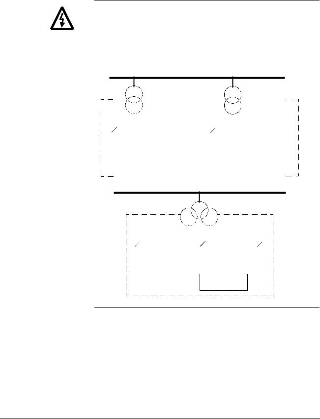
WARNING! Frame size R11i and above must be supplied with a transformer dedicated to drives and motors or equipment of equal or higher power, or with a transformer equipped with two secondary windings, one of which is dedicated to drives and motors. Resonances might occur if there is capacitive load (e.g. lighting, PC, PLC, small power factor compensation capacitors) in the same network with the drive. The resonance current might damage some unit in the network.
Medium voltage network
|
|
|
|
|
|
|
|
|
|
|
|
|
|
|
|
|
|
|
|
|
|
|
|
|
|
|
|
|
|
|
|
|
|
|
|
|
|
|
|
|
|
|
|
|
|
|
|
|
|
|
Supply transformer |
|
||||||||||
|
|
|
|
|
|
|
|
|
|
|
|
|
|
|
|
|
|
|
|
|
|
|
|
|
|
|
|
|
|
|
|
|
|
|
|
|
|
|
|
|
|
|
|
|
|
|
|
|
|
|
|
|
|
|
|
|
|
|
|
|
|
|
|
|
|
|
|
|
|
|
|
|
|
|
|
Neighbouring network |
|
|
|
|
|
|
|
|
|
|
|
|
|
|
|
|
|
|
|
|
|
|
|
|
|
|
|
|
|
|
|||||||||||||||||||
|
|
|
|
|
|
|
|
|
Low voltage |
|
|
|
|
|
|
|
|
|
|
|
|
|
|
|
|
|
|
|
Low voltage |
|
||||||||||||||||||||||||||||||||
|
|
|
|
|
|
|
|
|
|
|
|
|
|
|
|
|
|
|
|
|
|
|
|
|
|
|
|
|
||||||||||||||||||||||||||||||||||
|
|
|
|
|
|
|
|
|
|
|
|
|
|
|
|
|
|
|
|
|
|
|
|
|
|
|
|
|||||||||||||||||||||||||||||||||||
|
|
|
|
|
|
|
|
|
|
|
|
|
|
|
|
|
|
|
|
|
|
|
|
|
|
|
|
|||||||||||||||||||||||||||||||||||
|
|
|
|
|
|
|
|
|
|
|
|
|
|
|
|
|
|
|
|
|
|
|
|
|
|
|
||||||||||||||||||||||||||||||||||||
|
|
|
|
|
|
|
|
|
|
|
|
|
|
|
|
|
|
|
|
|
|
|
|
|
|
|
|
|
|
|
|
|
|
|
|
|
|
|
|
|
|
|
|
|
|
|
|
|
|
|
|
|
|
|
|
|
|
|
|
|
|
|
|
|
|
|
|
|
|
|
|
|
|
|
|
|
|
|
|
|
|
|
|
|
|
|
|
|
|
|
|
|
|
|
|
|
|
|
|
|
|
|
|
|
|
|
|
|
|
|
|
|
|
|
|
|
|
|
|
|
|
|
|
|
|
|
|
|
|
|
|
|
|
|
|
|
|
|
|
|
|
|
|
|
|
|
|
|
|
|
|
|
|
|
|
|
|
|
|
|
|
|
|
|
|
|
|
|
|
|
|
|
|
|
|
|
|
|
|
|
|
|
|
|
|
|
|
|
|
|
|
|
|
|
|
|
|
|
|
|
Other load than |
|
|
|
|
|
|
|
|
|
|
Motors |
|
|
|
|
|
|
|
|
|
Drive |
|
||||||||||||||||||||||||||||
|
|
|
|
|
|
|
|
|
|
|
|
|
|
|
|
|
|
|
|
|
|
|
|
|
|
|
|
|
|
|
|
|||||||||||||||||||||||||||||||
|
|
|
|
|
|
|
|
|
|
|
drives and motors |
|
|
|
|
|
|
|
|
|
|
|
|
|
|
|
|
|
|
|
|
|||||||||||||||||||||||||||||||
|
|
|
|
|
|
|
|
|
|
|
|
|
|
|
|
|
|
|
|
|
|
|
|
|
|
|
|
|
|
|
|
|
|
|
|
|
|
|
|
|
|
|
|
|
|
|||||||||||||||||
|
|
|
|
|
|
|
|
|
|
|
|
|
|
|
|
|
|
|
|
|
|
|
|
|
|
|
|
|
|
|
|
|
|
|
|
|
|
|
|
|
|
|
|
|
|
|
|
|
|
|
|
|
|
|
|
|
|
|
|
|
|
|
|
|
|
|
|
|
|
|
|
|
|
|
|
|
|
|
|
|
|
|
|
|
|
|
|
|
|
|
|
|
|
|
|
|
|
|
|
|
|
|
|
|
|
|
|
|
Other drives |
|
|
|
|
|
|
|
|||||||||
|
|
|
|
|
|
|
|
|
|
|
|
|
|
|
|
|
|
|
|
|
|
|
|
|
|
|
|
|
|
|
|
|
|
|
|
|
|
|
|
|
|
|
|
|
|
|
|
|
|
|
|
|
||||||||||
|
|
|
|
|
|
|
|
|
|
|
|
|
|
|
|
|
|
|
|
|
|
|
|
|
|
|
|
|
|
|
|
|
|
|
|
|
|
|
|
|
|
|
|
|
|
|
|
|
|
|
|
|
|
|
|
|
|
|
|
|
|
|
|
|
|
|
|
|
|
|
|
|
|
|
|
|
|
|
|
|
|
|
|
|
|
|
|
|
|
|
|
|
|
|
|
|
|
|
|
|
|
|
|
|
|
|
|
|
|
|
|
|
|
|
|
|
|
|
|
|
|
|
|
|
|
or
Medium voltage network
Supply transformer
|
|
|
|
|
|
|
|
|
|
|
|
|
|
|
|
|
|
|
Low voltage |
|
|
|
|
||||
|
Other load than |
|
|
|
|
|
|
|
|
Drive |
|
||
|
drives and motors |
|
|
|
|
|
|
|
|
|
|||
|
|
|
|
|
|
|
|
|
|
|
|
||
|
|
|
|
|
|
|
|
|
|
|
|
|
|
|
|
|
|
|
|
|
|
|
|
|
|
|
|
|
|
|
|
|
|
|
|
|
|
|
|
|
|
Other drives and motors
ACA 635 IGBT Supply Sections, ACS800-17 |
v |

Safety Instructions
vi |
ACA 635 IGBT Supply Sections, ACS800-17 |

Table of Contents
ACS 600 MultiDrive Manuals (Air-cooled Units, English Originals)
Safety Instructions
Overview . . . . . . . . . . . . . . . . . . . . . . . . . . . . . . . . . . . . . . . . . . . . . . . . . . . . . . . . . . . . . . . . . . . . . iii Installation and Maintenance Safety . . . . . . . . . . . . . . . . . . . . . . . . . . . . . . . . . . . . . . . . . . . . . . . . iii Automatic Resets . . . . . . . . . . . . . . . . . . . . . . . . . . . . . . . . . . . . . . . . . . . . . . . . . . . . . . . . . . . . . . . iv Dedicated Transformer . . . . . . . . . . . . . . . . . . . . . . . . . . . . . . . . . . . . . . . . . . . . . . . . . . . . . . . . . . . . v
Table of Contents
Update Notice for ACA 635 IGBT Supply Sections 260 to 4728 kVA ACS 800-17 Line-side Converter 120 to 1385 kVA
ACS 800-17 Line-side Converter . . . . . . . . . . . . . . . . . . . . . . . . . . . . . . . . . . . . . . . . . . . . . . . . . . . .1 Chapter 1 - About this Manual . . . . . . . . . . . . . . . . . . . . . . . . . . . . . . . . . . . . . . . . . . . . . . . . . . . . . .1 Chapter 2 - Operation Basics . . . . . . . . . . . . . . . . . . . . . . . . . . . . . . . . . . . . . . . . . . . . . . . . . . . . . . .1 Chapter 3 - Hardware Description . . . . . . . . . . . . . . . . . . . . . . . . . . . . . . . . . . . . . . . . . . . . . . . . . . .2 Chapter 8 - Parameters . . . . . . . . . . . . . . . . . . . . . . . . . . . . . . . . . . . . . . . . . . . . . . . . . . . . . . . . . . .4 Appendix A - Technical Data . . . . . . . . . . . . . . . . . . . . . . . . . . . . . . . . . . . . . . . . . . . . . . . . . . . . . . .6 Appendix B Circuit Diagrams . . . . . . . . . . . . . . . . . . . . . . . . . . . . . . . . . . . . . . . . . . . . . . . . . . . . . .12
Chapter 1 – About this Manual
What this Chapter Contains . . . . . . . . . . . . . . . . . . . . . . . . . . . . . . . . . . . . . . . . . . . . . . . . . . . . . . . .1 Intended Audience . . . . . . . . . . . . . . . . . . . . . . . . . . . . . . . . . . . . . . . . . . . . . . . . . . . . . . . . . . . . . . .1 Parameter Setting . . . . . . . . . . . . . . . . . . . . . . . . . . . . . . . . . . . . . . . . . . . . . . . . . . . . . . . . . . . . . . .1 To which Products this Manual Applies . . . . . . . . . . . . . . . . . . . . . . . . . . . . . . . . . . . . . . . . . . . . . . .1 Contents . . . . . . . . . . . . . . . . . . . . . . . . . . . . . . . . . . . . . . . . . . . . . . . . . . . . . . . . . . . . . . . . . . . . . . .1 ISU-related Information in Other Manuals . . . . . . . . . . . . . . . . . . . . . . . . . . . . . . . . . . . . . . . . . . . . . 2
Chapter 2 – Operation Basics
Operation of ISU . . . . . . . . . . . . . . . . . . . . . . . . . . . . . . . . . . . . . . . . . . . . . . . . . . . . . . . . . . . . . . . . .1
Main Circuit Diagram . . . . . . . . . . . . . . . . . . . . . . . . . . . . . . . . . . . . . . . . . . . . . . . . . . . . . . . . . . . . .1
Control . . . . . . . . . . . . . . . . . . . . . . . . . . . . . . . . . . . . . . . . . . . . . . . . . . . . . . . . . . . . . . . . . . . . . . . .1
Voltage and Current Waveforms . . . . . . . . . . . . . . . . . . . . . . . . . . . . . . . . . . . . . . . . . . . . . . . . . . . .2
DC Current . . . . . . . . . . . . . . . . . . . . . . . . . . . . . . . . . . . . . . . . . . . . . . . . . . . . . . . . . . . . . . . . . . 2
Distortion . . . . . . . . . . . . . . . . . . . . . . . . . . . . . . . . . . . . . . . . . . . . . . . . . . . . . . . . . . . . . . . . . . . . . .3
Spectrum of the Voltage DIstortion . . . . . . . . . . . . . . . . . . . . . . . . . . . . . . . . . . . . . . . . . . . . . . . . 3
Spectrum of the Line Current Distortion . . . . . . . . . . . . . . . . . . . . . . . . . . . . . . . . . . . . . . . . . . . . 3
Chapter 3 – Hardware Description
Main Components of a Drive with ISU . . . . . . . . . . . . . . . . . . . . . . . . . . . . . . . . . . . . . . . . . . . . . . . .1
ACA 635 IGBT Supply Sections User’s Manual |
vii |

Supply Section . . . . . . . . . . . . . . . . . . . . . . . . . . . . . . . . . . . . . . . . . . . . . . . . . . . . . . . . . . . . . . . . . 1
Auxiliary Control Unit . . . . . . . . . . . . . . . . . . . . . . . . . . . . . . . . . . . . . . . . . . . . . . . . . . . . . . . . . . .2
Incoming Unit . . . . . . . . . . . . . . . . . . . . . . . . . . . . . . . . . . . . . . . . . . . . . . . . . . . . . . . . . . . . . . . . .2
Filter Unit . . . . . . . . . . . . . . . . . . . . . . . . . . . . . . . . . . . . . . . . . . . . . . . . . . . . . . . . . . . . . . . . . . . .2
IGBT Supply Unit . . . . . . . . . . . . . . . . . . . . . . . . . . . . . . . . . . . . . . . . . . . . . . . . . . . . . . . . . . . . . .4
Main Circuit Construction . . . . . . . . . . . . . . . . . . . . . . . . . . . . . . . . . . . . . . . . . . . . . . . . . . . . . . . . . 5
Configurations . . . . . . . . . . . . . . . . . . . . . . . . . . . . . . . . . . . . . . . . . . . . . . . . . . . . . . . . . . . . . . . . . . 5
Basic Configuration. . . . . . . . . . . . . . . . . . . . . . . . . . . . . . . . . . . . . . . . . . . . . . . . . . . . . . . . . . . . .5
Parallel Connected Modules . . . . . . . . . . . . . . . . . . . . . . . . . . . . . . . . . . . . . . . . . . . . . . . . . . . . .5
Braking Chopper. . . . . . . . . . . . . . . . . . . . . . . . . . . . . . . . . . . . . . . . . . . . . . . . . . . . . . . . . . . . . . .6
Chapter 4 – Commissioning the Supply Section with ISU |
|
Overview . . . . . . . . . . . . . . . . . . . . . . . . . . . . . . . . . . . . . . . . . . . . . . . . . . . . . . . . . . . . . . . . . . . . . . |
1 |
Installation Checklist . . . . . . . . . . . . . . . . . . . . . . . . . . . . . . . . . . . . . . . . . . . . . . . . . . . . . . . . . . . . . |
1 |
Checks with No Voltage Connected . . . . . . . . . . . . . . . . . . . . . . . . . . . . . . . . . . . . . . . . . . . . . . . . . |
2 |
Connecting Voltage to Auxiliary Circuits . . . . . . . . . . . . . . . . . . . . . . . . . . . . . . . . . . . . . . . . . . . . . . |
3 |
Checks with Voltage Connected to Auxiliary Circuits . . . . . . . . . . . . . . . . . . . . . . . . . . . . . . . . . . . . . |
4 |
Connecting Voltage to IGBT Supply Unit . . . . . . . . . . . . . . . . . . . . . . . . . . . . . . . . . . . . . . . . . . . . . |
5 |
Starting . . . . . . . . . . . . . . . . . . . . . . . . . . . . . . . . . . . . . . . . . . . . . . . . . . . . . . . . . . . . . . . . . . . . . . . |
6 |
Checks with ISU Supply Started . . . . . . . . . . . . . . . . . . . . . . . . . . . . . . . . . . . . . . . . . . . . . . . . . . . . |
7 |
Parameters . . . . . . . . . . . . . . . . . . . . . . . . . . . . . . . . . . . . . . . . . . . . . . . . . . . . . . . . . . . . . . . . . . . . |
7 |
Controlling the ISU with an Overriding System . . . . . . . . . . . . . . . . . . . . . . . . . . . . . . . . . . . . . . . . . |
8 |
Fieldbus Adapters . . . . . . . . . . . . . . . . . . . . . . . . . . . . . . . . . . . . . . . . . . . . . . . . . . . . . . . . . . . . . . . |
9 |
On-load Checks . . . . . . . . . . . . . . . . . . . . . . . . . . . . . . . . . . . . . . . . . . . . . . . . . . . . . . . . . . . . . . . . . |
9 |
Chapter 5 – Earth Fault Protection
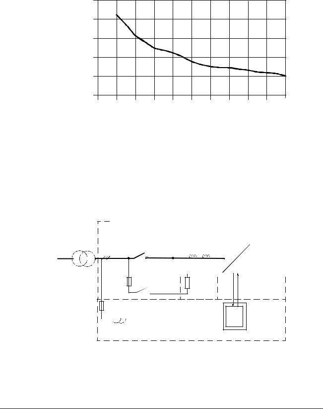
Overview . . . . . . . . . . . . . . . . . . . . . . . . . . . . . . . . . . . . . . . . . . . . . . . . . . . . . . . . . . . . . . . . . . . . . . 1
Floating Network . . . . . . . . . . . . . . . . . . . . . . . . . . . . . . . . . . . . . . . . . . . . . . . . . . . . . . . . . . . . . . . . 1
Insulation Monitoring Device . . . . . . . . . . . . . . . . . . . . . . . . . . . . . . . . . . . . . . . . . . . . . . . . . . . . .1
System-earthed Network . . . . . . . . . . . . . . . . . . . . . . . . . . . . . . . . . . . . . . . . . . . . . . . . . . . . . . . . . . 2
Chapter 6 – Firmware Description
Overview . . . . . . . . . . . . . . . . . . . . . . . . . . . . . . . . . . . . . . . . . . . . . . . . . . . . . . . . . . . . . . . . . . . . . . 1
Control Principle . . . . . . . . . . . . . . . . . . . . . . . . . . . . . . . . . . . . . . . . . . . . . . . . . . . . . . . . . . . . . . . . 1
Identification Routine . . . . . . . . . . . . . . . . . . . . . . . . . . . . . . . . . . . . . . . . . . . . . . . . . . . . . . . . . . . . . 3
Charging . . . . . . . . . . . . . . . . . . . . . . . . . . . . . . . . . . . . . . . . . . . . . . . . . . . . . . . . . . . . . . . . . . . . . . 4
Synchronization . . . . . . . . . . . . . . . . . . . . . . . . . . . . . . . . . . . . . . . . . . . . . . . . . . . . . . . . . . . . . . . . . 4
Starting Sequence . . . . . . . . . . . . . . . . . . . . . . . . . . . . . . . . . . . . . . . . . . . . . . . . . . . . . . . . . . . . . . . 5
Start by the Starting Switch . . . . . . . . . . . . . . . . . . . . . . . . . . . . . . . . . . . . . . . . . . . . . . . . . . . . . .6
Start via Fieldbus . . . . . . . . . . . . . . . . . . . . . . . . . . . . . . . . . . . . . . . . . . . . . . . . . . . . . . . . . . . . . .7
Stop . . . . . . . . . . . . . . . . . . . . . . . . . . . . . . . . . . . . . . . . . . . . . . . . . . . . . . . . . . . . . . . . . . . . . . . . . . 8
Missing Phase . . . . . . . . . . . . . . . . . . . . . . . . . . . . . . . . . . . . . . . . . . . . . . . . . . . . . . . . . . . . . . . . . . 8
Control Diagram . . . . . . . . . . . . . . . . . . . . . . . . . . . . . . . . . . . . . . . . . . . . . . . . . . . . . . . . . . . . . . . . 9
Controllers . . . . . . . . . . . . . . . . . . . . . . . . . . . . . . . . . . . . . . . . . . . . . . . . . . . . . . . . . . . . . . . . . . . . . 9
DC Voltage Controller. . . . . . . . . . . . . . . . . . . . . . . . . . . . . . . . . . . . . . . . . . . . . . . . . . . . . . . . . .10
Reactive Power Control . . . . . . . . . . . . . . . . . . . . . . . . . . . . . . . . . . . . . . . . . . . . . . . . . . . . . . . .11
viii |
ACA 635 IGBT Supply Sections User’s Manual |
Chapter 7 – Fault Tracing
Overview . . . . . . . . . . . . . . . . . . . . . . . . . . . . . . . . . . . . . . . . . . . . . . . . . . . . . . . . . . . . . . . . . . . . . .1 Fault Tracing . . . . . . . . . . . . . . . . . . . . . . . . . . . . . . . . . . . . . . . . . . . . . . . . . . . . . . . . . . . . . . . . . . .1 Fault Resetting . . . . . . . . . . . . . . . . . . . . . . . . . . . . . . . . . . . . . . . . . . . . . . . . . . . . . . . . . . . . . . . 1 Fault History . . . . . . . . . . . . . . . . . . . . . . . . . . . . . . . . . . . . . . . . . . . . . . . . . . . . . . . . . . . . . . . . . 2 Fault and Warning Messages . . . . . . . . . . . . . . . . . . . . . . . . . . . . . . . . . . . . . . . . . . . . . . . . . . . . 2 What to Do in Case of an Earth Fault Indication . . . . . . . . . . . . . . . . . . . . . . . . . . . . . . . . . . . . . . . . 6 Flowchart . . . . . . . . . . . . . . . . . . . . . . . . . . . . . . . . . . . . . . . . . . . . . . . . . . . . . . . . . . . . . . . . . . . . 7
Chapter 8 – Parameters |
|
|
Overview . . . . . . . . . . . . . . . . . . . . . . . . . . . . . . . . . . . . . . . . . . . . . . . . . . . . . . . . . . . . . . . . . . . . . . |
1 |
|
1 |
Actual Signals . . . . . . . . . . . . . . . . . . . . . . . . . . . . . . . . . . . . . . . . . . . . . . . . . . . . . . . . . . . . . . . . . |
2 |
2 |
Actual Signals . . . . . . . . . . . . . . . . . . . . . . . . . . . . . . . . . . . . . . . . . . . . . . . . . . . . . . . . . . . . . . . . . |
3 |
3 |
Actual Signals . . . . . . . . . . . . . . . . . . . . . . . . . . . . . . . . . . . . . . . . . . . . . . . . . . . . . . . . . . . . . . . . . |
3 |
4 |
Information . . . . . . . . . . . . . . . . . . . . . . . . . . . . . . . . . . . . . . . . . . . . . . . . . . . . . . . . . . . . . . . . . . . |
4 |
7 |
Control Word . . . . . . . . . . . . . . . . . . . . . . . . . . . . . . . . . . . . . . . . . . . . . . . . . . . . . . . . . . . . . . . . . . |
5 |
8 |
Status Word . . . . . . . . . . . . . . . . . . . . . . . . . . . . . . . . . . . . . . . . . . . . . . . . . . . . . . . . . . . . . . . . . . . |
5 |
9 |
Fault Words . . . . . . . . . . . . . . . . . . . . . . . . . . . . . . . . . . . . . . . . . . . . . . . . . . . . . . . . . . . . . . . . . . . |
6 |
11 |
Reference Selects . . . . . . . . . . . . . . . . . . . . . . . . . . . . . . . . . . . . . . . . . . . . . . . . . . . . . . . . . . . . |
.9 |
13 |
Analogue Inputs . . . . . . . . . . . . . . . . . . . . . . . . . . . . . . . . . . . . . . . . . . . . . . . . . . . . . . . . . . . . . |
.9 |
14 |
Digital Outputs . . . . . . . . . . . . . . . . . . . . . . . . . . . . . . . . . . . . . . . . . . . . . . . . . . . . . . . . . . . . . . . |
10 |
15 |
Analogue Outputs . . . . . . . . . . . . . . . . . . . . . . . . . . . . . . . . . . . . . . . . . . . . . . . . . . . . . . . . . . . . |
11 |
16 |
System Control Inputs . . . . . . . . . . . . . . . . . . . . . . . . . . . . . . . . . . . . . . . . . . . . . . . . . . . . . . . . . |
12 |
18 |
LED Panel Control . . . . . . . . . . . . . . . . . . . . . . . . . . . . . . . . . . . . . . . . . . . . . . . . . . . . . . . . . . . . |
13 |
19 |
Data Storage . . . . . . . . . . . . . . . . . . . . . . . . . . . . . . . . . . . . . . . . . . . . . . . . . . . . . . . . . . . . . . . . |
14 |
|
Trend Monitoring with Drive Window . . . . . . . . . . . . . . . . . . . . . . . . . . . . . . . . . . . . . . . . . . . . . |
14 |
|
Sending a value. . . . . . . . . . . . . . . . . . . . . . . . . . . . . . . . . . . . . . . . . . . . . . . . . . . . . . . . . . . . . . |
14 |
|
19 Data Storage Parameter Table . . . . . . . . . . . . . . . . . . . . . . . . . . . . . . . . . . . . . . . . . . . . . . . |
15 |
21 |
Start/Stop Functions . . . . . . . . . . . . . . . . . . . . . . . . . . . . . . . . . . . . . . . . . . . . . . . . . . . . . . . . . . |
16 |
23 DC Bus Reference . . . . . . . . . . . . . . . . . . . . . . . . . . . . . . . . . . . . . . . . . . . . . . . . . . . . . . . . . . . |
18 |
|
|
Example. . . . . . . . . . . . . . . . . . . . . . . . . . . . . . . . . . . . . . . . . . . . . . . . . . . . . . . . . . . . . . . . . . . . |
18 |
24 |
Reactive Power . . . . . . . . . . . . . . . . . . . . . . . . . . . . . . . . . . . . . . . . . . . . . . . . . . . . . . . . . . . . . . |
18 |
30 |
Fault Functions . . . . . . . . . . . . . . . . . . . . . . . . . . . . . . . . . . . . . . . . . . . . . . . . . . . . . . . . . . . . . . |
19 |
51 |
Communication Module . . . . . . . . . . . . . . . . . . . . . . . . . . . . . . . . . . . . . . . . . . . . . . . . . . . . . . . . |
20 |
70 DDCS Control . . . . . . . . . . . . . . . . . . . . . . . . . . . . . . . . . . . . . . . . . . . . . . . . . . . . . . . . . . . . . . . |
20 |
|
71 |
DriveBus Communication . . . . . . . . . . . . . . . . . . . . . . . . . . . . . . . . . . . . . . . . . . . . . . . . . . . . . . |
22 |
90, 91 Data Set Receive Addresses . . . . . . . . . . . . . . . . . . . . . . . . . . . . . . . . . . . . . . . . . . . . . . . . |
23 |
|
92, 93 Data Set Transmit Addresses . . . . . . . . . . . . . . . . . . . . . . . . . . . . . . . . . . . . . . . . . . . . . . . . |
24 |
|
98 |
Option Modules . . . . . . . . . . . . . . . . . . . . . . . . . . . . . . . . . . . . . . . . . . . . . . . . . . . . . . . . . . . . . . |
25 |
99 |
Start-up Data . . . . . . . . . . . . . . . . . . . . . . . . . . . . . . . . . . . . . . . . . . . . . . . . . . . . . . . . . . . . . . . . |
26 |
Appendix A – Technical Data
Ratings . . . . . . . . . . . . . . . . . . . . . . . . . . . . . . . . . . . . . . . . . . . . . . . . . . . . . . . . . . . . . . . . . . . . . . . .1
Abbreviations. . . . . . . . . . . . . . . . . . . . . . . . . . . . . . . . . . . . . . . . . . . . . . . . . . . . . . . . . . . . . . . . . 1
Notes . . . . . . . . . . . . . . . . . . . . . . . . . . . . . . . . . . . . . . . . . . . . . . . . . . . . . . . . . . . . . . . . . . . . . . . 1
Ratings 380...690 V . . . . . . . . . . . . . . . . . . . . . . . . . . . . . . . . . . . . . . . . . . . . . . . . . . . . . . . . . . . . 2
Dimensions and Weights . . . . . . . . . . . . . . . . . . . . . . . . . . . . . . . . . . . . . . . . . . . . . . . . . . . . . . . . . .3
ACA 635 IGBT Supply Sections User’s Manual |
ix |

Input Power Connection . . . . . . . . . . . . . . . . . . . . . . . . . . . . . . . . . . . . . . . . . . . . . . . . . . . . . . . . . . 4 Harmonic Distortion . . . . . . . . . . . . . . . . . . . . . . . . . . . . . . . . . . . . . . . . . . . . . . . . . . . . . . . . . . . .5 Switching Frequency . . . . . . . . . . . . . . . . . . . . . . . . . . . . . . . . . . . . . . . . . . . . . . . . . . . . . . . . . . . . . 5 Ambient Conditions . . . . . . . . . . . . . . . . . . . . . . . . . . . . . . . . . . . . . . . . . . . . . . . . . . . . . . . . . . . . . . 5 Efficiency . . . . . . . . . . . . . . . . . . . . . . . . . . . . . . . . . . . . . . . . . . . . . . . . . . . . . . . . . . . . . . . . . . . . . . 5 Fuses . . . . . . . . . . . . . . . . . . . . . . . . . . . . . . . . . . . . . . . . . . . . . . . . . . . . . . . . . . . . . . . . . . . . . . . . . 6 IGBT Supply Section AC Fuses . . . . . . . . . . . . . . . . . . . . . . . . . . . . . . . . . . . . . . . . . . . . . . . . . . .6 IGBT Supply Unit DC Fuses . . . . . . . . . . . . . . . . . . . . . . . . . . . . . . . . . . . . . . . . . . . . . . . . . . . . .7 Power Cable Entries . . . . . . . . . . . . . . . . . . . . . . . . . . . . . . . . . . . . . . . . . . . . . . . . . . . . . . . . . . . . . 7 Tightening Torque. . . . . . . . . . . . . . . . . . . . . . . . . . . . . . . . . . . . . . . . . . . . . . . . . . . . . . . . . . . . . .7 Marking . . . . . . . . . . . . . . . . . . . . . . . . . . . . . . . . . . . . . . . . . . . . . . . . . . . . . . . . . . . . . . . . . . . . . .7 IGBT Supply Sections. . . . . . . . . . . . . . . . . . . . . . . . . . . . . . . . . . . . . . . . . . . . . . . . . . . . . . . . . . .8 Drive Control Unit NDCU-51 . . . . . . . . . . . . . . . . . . . . . . . . . . . . . . . . . . . . . . . . . . . . . . . . . . . . . . . 9 NIOC Board Connections . . . . . . . . . . . . . . . . . . . . . . . . . . . . . . . . . . . . . . . . . . . . . . . . . . . . . . . . 10 NIOC Board Specifications . . . . . . . . . . . . . . . . . . . . . . . . . . . . . . . . . . . . . . . . . . . . . . . . . . . . . . . 11 Drive Control Unit RDCU . . . . . . . . . . . . . . . . . . . . . . . . . . . . . . . . . . . . . . . . . . . . . . . . . . . . . . . . . 12 Motor Control and I/O board RMIO-01 . . . . . . . . . . . . . . . . . . . . . . . . . . . . . . . . . . . . . . . . . . . . . . 14 RMIO board specifications . . . . . . . . . . . . . . . . . . . . . . . . . . . . . . . . . . . . . . . . . . . . . . . . . . . . . . . 16 Applicable Standards . . . . . . . . . . . . . . . . . . . . . . . . . . . . . . . . . . . . . . . . . . . . . . . . . . . . . . . . . . . 17 CE Marking . . . . . . . . . . . . . . . . . . . . . . . . . . . . . . . . . . . . . . . . . . . . . . . . . . . . . . . . . . . . . . . . . . . 17 Definitions. . . . . . . . . . . . . . . . . . . . . . . . . . . . . . . . . . . . . . . . . . . . . . . . . . . . . . . . . . . . . . . . . . .17 Compliance with the EMC Directive . . . . . . . . . . . . . . . . . . . . . . . . . . . . . . . . . . . . . . . . . . . . . .18 Machinery Directive . . . . . . . . . . . . . . . . . . . . . . . . . . . . . . . . . . . . . . . . . . . . . . . . . . . . . . . . . . .18
Appendix B – Circuit Diagrams
Overview . . . . . . . . . . . . . . . . . . . . . . . . . . . . . . . . . . . . . . . . . . . . . . . . . . . . . . . . . . . . . . . . . . . . . . 1
x |
ACA 635 IGBT Supply Sections User’s Manual |
Update Notice for ACA 635 IGBT Supply Sections 260 to 4728 kVA ACS 800-17 Line-side Converter 120 to 1385 kVA
The notice concerns The translation (DE revision C) of the ACA 635 IGBT Supply Sections 260 to 4728 kVA, ACS 800-17 Line-side Converter 120 to 1385 kVA User’s Manual: code 3BFE 64495062
The notice is in use |
from 28.07.2003 |
The notice contains |
Updates to the REV C translation. |
|
|
ACS 800-17 Line-side |
CHANGED: ACS/ACC 617 line-side converter has been replaced by |
Converter |
the ACS 800-17 line-side converter. |
Chapter 1 - About this Page 1-2, User Interface CHANGED: The user interface of the IGBT
Manual Supply Unit is a CDP 312 Control Panel or a PC, which is equipped with a DDCS board and DriveWindow.
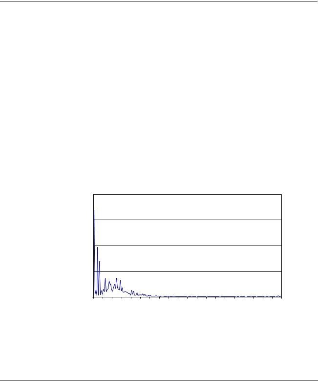
Chapter 2 - Operation Page 2-3 CHANGED: Voltage and current distortion
Basics
Spectrum of the Voltage Distortion
2 |
|
|
|
|
|
|
|
|
|
|
|
|
|
|
|
|
|
|
|
1,5 |
|
|
|
|
|
|
|
|
|
|
|
|
|
|
|
|
|
|
|
1 |
|
|
|
|
|
|
|
|
|
|
|
|
|
|
|
|
|
|
|
0,5 |
|
|
|
|
|
|
|
|
|
|
|
|
|
|
|
|
|
|
|
0 |
|
|
|
|
|
|
|
|
|
|
|
|
|
|
|
|
|
|
|
THD |
11 |
21 |
31 |
41 |
51 |
61 |
71 |
81 |
91 |
101 |
111 |
121 |
131 |
141 |
151 |
161 |
171 |
181 |
191 |
Update notice |
1 |
Update Notice
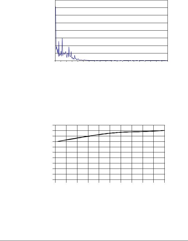
Spectrum of the Current Distortion
4 |
|
|
|
|
|
|
|
|
|
|
|
|
|
|
|
|
|
|
|
3,5 |
|
|
|
|
|
|
|
|
|
|
|
|
|
|
|
|
|
|
|
3 |
|
|
|
|
|
|
|
|
|
|
|
|
|
|
|
|
|
|
|
2,5 |
|
|
|
|
|
|
|
|
|
|
|
|
|
|
|
|
|
|
|
2 |
|
|
|
|
|
|
|
|
|
|
|
|
|
|
|
|
|
|
|
1,5 |
|
|
|
|
|
|
|
|
|
|
|
|
|
|
|
|
|
|
|
1 |
|
|
|
|
|
|
|
|
|
|
|
|
|
|
|
|
|
|
|
0,5 |
|
|
|
|
|
|
|
|
|
|
|
|
|
|
|
|
|
|
|
0 |
|
|
|
|
|
|
|
|
|
|
|
|
|
|
|
|
|
|
|
THD |
11 |
21 |
31 |
41 |
51 |
61 |
71 |
81 |
91 |
101 |
111 |
121 |
131 |
141 |
151 |
161 |
171 |
181 |
191 |
Chapter 3 - Hardware
Description
Page 3-2, Incoming Unit CHANGED: Frames R6i to R9i: switch fuse (including AC fuses) and main contactor. Frames R11i and above: air circuit breaker.
Page 3-3 CHANGED: Current and voltage distortion
Current Distortion (up to 200th) Generated by the Supply Unit at PCC (Point of Common Coupling)
|
5 |
|
|
|
|
|
|
|
|
|
|
|
4.5 |
|
|
|
|
|
|
|
|
|
|
|
4 |
|
|
|
|
|
|
|
|
|
|
| <![if ! IE]> <![endif]>[%] |
3.5 |
|
|
|
|
|
|
|
|
|
|
|
|
|
|
|
|
|
|
|
|
|
|
| <![if ! IE]> <![endif]>THD |
3 |
|
|
|
|
|
|
|
|
|
|
2.5 |
|
|
|
|
|
|
|
|
|
|
|
| <![if ! IE]> <![endif]>Current |
|
|
|
|
|
|
|
|
|
|
|
2 |
|
|
|
|
|
|
|
|
|
|
|
1.5 |
|
|
|
|
|
|
|
|
|
|
|
|
1 |
|
|
|
|
|
|
|
|
|
|
|
0.5 |
|
|
|
|
|
|
|
|
|
|
|
0 |
|
|
|
|
|
|
|
|
|
|
|
0 |
10 |
20 |
30 |
40 |
50 |
60 |
70 |
80 |
90 |
100 |
Rsc (Short-circuit Ratio) at PCC
2 |
Update notice |
Update Notice
Voltage Distortion (up to 200th) Generated by the Supply Unit at
PCC (Point of Common Coupling)
|
5 |
|
|
|
|
|
|
|
|
|
|
|
4 |
|
|
|
|
|
|
|
|
|
|
| <![if ! IE]> <![endif]>[%] |
|
|
|
|
|
|
|
|
|
|
|
| <![if ! IE]> <![endif]>THD |
3 |
|
|
|
|
|
|
|
|
|
|
|
|
|
|
|
|
|
|
|
|
|
|
| <![if ! IE]> <![endif]>Voltage |
2 |
|
|
|
|
|
|
|
|
|
|
|
|
|
|
|
|
|
|
|
|
|
|
|
1 |
|
|
|
|
|
|
|
|
|
|
|
0 |
|
|
|
|
|
|
|
|
|
|
|
0 |
10 |
20 |
30 |
40 |
50 |
60 |
70 |
80 |
90 |
100 |
Rsc (Short-circuit Ratio) at PCC
Page 3-5 Basic Configuration CHANGED:
The hardware of the IGBT supply unit is similar to the hardware of the ACS 600 MultiDrive inverter. One NAMC/RMIO board controls the converter module. It is located inside the Drive Control Unit (NDCU/ RDCU) box. The supply section is equipped with an LCL filter, DC fuses and AC fuses/switch fuse OESA. AC fuses are used with a breaker and a switch fuse is used with a contactor.
|
|
|
|
|
|
|
|
|
ICU |
|
|
|
|
|
|
|
|
|
FIU |
|
|
|
|
|
ISU |
|||||||||||||||||||||||||||
|
|
|
|
|
|
|
|
|
|
|
|
|
|
|
|
|
|
|
|
|
|
|
|
|
|
|
|
|
|
|
|
|
|
|
|
|
|
|
|
|
|
|
|
|
|
|
|
|
|
|
||
|
|
|
|
|
|
|
|
|
|
|
|
|
|
|
|
|
|
|
|
|
|
|
|
|
|
|
|
|
|
|
|
|
Converter |
|
|
|
|
|
|
|
|
|
|
|||||||||
|
|
|
|
|
|
|
|
|
|
|
|
|
|
|
|
|
|
|
|
|
|
|
|
|
|
|
|
|
|
|
|
|
|
|
|
|
|
|
|
|
|
|
||||||||||
|
|
|
|
|
|
|
|
|
|
|
|
|
|
|
|
|
|
|
|
|
|
|
|
|
|
|
|
|
|
|
|
|
Module |
|
|
|
|
|
|
|
|
|
|
|||||||||
|
|
|
|
|
|
|
|
|
|
|
|
|
|
|
|
|
|
|
|
|
|
|
|
|
|
|
|
|
|
|
|
|
|
|
|
|
|
|
|
|
|
|
||||||||||
OESA |
AC fuses |
|
|
|
|
|
|
|
|
|
|
|
|
|
|
|
|
|
|
|
|
|
|
|
|
DC fuses |
|
|||||||||||||||||||||||||
|
|
|
|
|
|
|
|
|
|
|
|
|
|
|
|
|
|
|
|
|
|
|
|
|
||||||||||||||||||||||||||||
~ |
|
|
|
|
|
|
|
|
||||||||||||||||||||||||||||||||||||||||||||
|
|
|
|
|
|
|
|
|
|
|
|
|
|
|
|
|
|
|
|
|
|
|
|
|
|
|
|
|
|
|
|
|
|
|
|
|
|
|
|
|
|
|
|
|
|
|
|
|
|
|||
|
|
|
|
|
|
|
|
|
|
|
|
|
|
|
|
|
|
|
|
|
|
|
|
|
|
|
|
|
|
|
|
|
= |
|
|
|
|
|
|
|
|
|
|
|
|
|
|
|||||
|
|
|
|
|
|
|
|
|
|
|
|
|
|
|
|
|
|
|
|
|
|
|
|
|
|
|
|
|
|
|
|
|
|
|
|
|
|
|
|
|
|
|
|
|
|
|
||||||
|
|
|
|
|
|
|
|
|
|
|
|
|
|
|
|
|
|
|
|
|
|
|
|
|
|
|
|
|
|
|
|
|
|
|
|
|
|
|
|
|
|
|
|
|
|
|
||||||
|
|
|
|
|
|
|
|
|
|
|
|
|
|
|
|
|
|
|
|
|
|
|
|
|
|
|
|
|
|
|
|
|
|
|
|
|
|
|
|
|
|
|
|
|
|
|
|
|
|
|
|
|
Charging circuit

 230/115 V
| <![if ! IE]> <![endif]>NAMC/ |
<![if ! IE]> <![endif]>RMIO |
NDCU/RDCU
ACU
Update notice |
3 |

Update Notice
Chapter 8 - Parameters Page 8-2 CHANGED:
Code |
Parameter |
Range/Unit |
Description |
Integer Scaling |
1 |
ACTUAL |
|
|
|
|
SIGNALS |
|
|
|
1.19 |
AI1 [V] |
0...10 |
Non-scaled value of analogue input |
10000 = 10 V or |
|
|
|
AI1. See Par. 13.01 AI1 HIGH |
20 mA |
|
|
|
VALUE and 13.02 AI1 LOW VALUE. |
|
Page 8-4 CHANGED:
The software version (Parameters 4.01 and 4.03) is expressed as follows:
Character Example |
Meaning |
|
|
|||
no |
|
|
|
|
|
|
1 |
I |
|
I = Input bridge software |
|
||
2 |
X |
|
Product: X= ISU |
|
|
|
3 |
X |
|
Software type: |
|
|
|
|
|
|
A = application software (Parameter 4.03) |
|
||
4 |
G |
|
Control board: G = NAMC-51, R = RMIO |
|
||
5 to 8 |
6000 |
|
Software version number: 6000 = NAMC-51, |
|
||
|
|
|
7000 = RMIO |
|
|
|
Page 8-9 ADDED: |
|
|
|
|
||
|
|
|
|
|
|
|
Code |
Parameter |
T |
Default |
Alternative |
Description |
Integer |
|
|
y |
|
Settings |
|
Scaling |
|
|
p |
|
( ) Fieldbus |
|
|
|
|
e |
|
Equivalent |
|
|
13 |
ANALOGUE |
|
|
|
|
|
|
INPUTS |
|
|
|
|
|
13.12 |
MINIMUM |
I |
0 V |
(1) 0 V |
This value corresponds to the |
|
|
AI1 |
|
|
(2) -10 V |
minimum reference from |
|
|
|
|
|
|
analogue input AI1. |
|
4 |
Update notice |

|
|
|
|
|
Update Notice |
|
Page 8-22 CHANGED: |
|
|
|
|||
|
|
|
|
|
|
|
Code |
Parameter |
T |
Default |
Alternative |
Description |
Integer |
|
|
y |
|
Settings |
|
Scaling |
|
|
p |
|
|
||
|
|
|
( ) Fieldbus |
|
|
|
|
|
e |
|
|
|
|
|
|
|
|
Equivalent |
|
|
70 |
DDCS |
|
|
|
|
|
|
CONTROL |
|
|
|
|
|
70.20 |
CH3 HW |
B |
STAR |
|
This parameter is used for |
1=1 |
|
CONNECTION |
|
|
|
enabling or disabling |
|
|
|
|
|
|
regeneration of channel CH3 |
|
|
|
|
|
|
optical transmitter. In |
|
|
|
|
|
|
regeneration mode any |
|
|
|
|
|
|
message received by the |
|
|
|
|
|
|
channel is echoed back. |
|
|
|
|
|
(0) RING |
Regeneration enabled. Select |
|
|
|
|
|
|
RING if the CH3 channels on |
|
|
|
|
|
|
the NAMC boards / RDCO |
|
|
|
|
|
|
modules are connected to a |
|
|
|
|
|
|
ring configuration. |
|
|
|
|
|
(1) STAR |
Regeneration disabled. |
|
|
|
|
|
|
Select STAR with a star |
|
|
|
|
|
|
configuration such as |
|
|
|
|
|
|
DriveWindow (PC) – NDBU- |
|
|
|
|
|
|
95 optical branching unit(s) – |
|
|
|
|
|
|
NAMC board / RDCO module |
|
|
|
|
|
|
(RMIO board). |
|
Page 8-23 CHANGED: D SET 10 VAL 1 denotes the receive address of data set 10 value 1.
Page 8-24 CHANGED: D SET 11 VAL 1 denotes the transmit address of data set 11 value 1.
Update notice |
5 |
Update Notice
Appendix A -
Technical Data
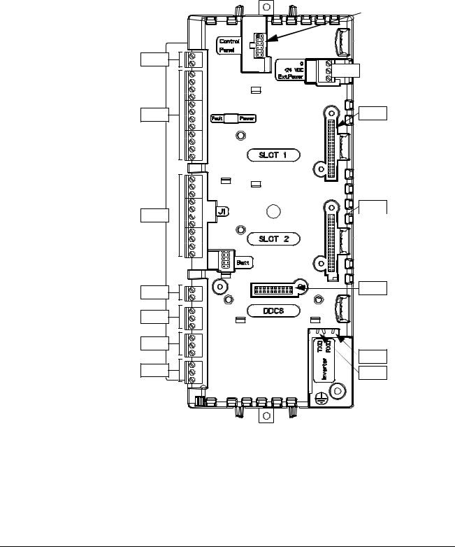
Page A-9 ADDED: Drive Control Unit RDCU has been added to the manual. The RDCU unit replaces the NDCU-51 unit. The Drive Control Unit RDCU containing an RMIO-01 board is shown in the pictures below.
Interface for
CDP312
Control Panel
X20 |
X34 |
|
|
X21 |
X31 |
X32 X22 


X23 |
X33 |
|
|
X25 |
|
X26 |
X68 |
|
X27 |
||
X57 |
6 |
Update notice |

Update Notice
Update notice |
7 |

Update Notice
External control cable connections (non-US) to the RMIO board for the ACS 800 Standard Application Program (Factory Macro) are shown below. For external control connections of other application macros and programs, see the appropriate Firmware Manual.
Terminal block size:
cables 0.3 to 3.3 mm2 (22 to 12 AWG)
Tightening torque:
0.2 to 0.4 Nm (2 to 4 lbf in.)
1) Only effective if par. 10.03 is set to REQUEST by the user.
2) 0 = open, 1 = closed
DI4 |
Ramp times according to |
0 |
parameters 22.02 and 22.03 |
1 |
parameters 22.04 and 22.05 |
3) |
See par. group 12 CONSTANT |
||
|
SPEEDS. |
||
|
|
|
|
DI5 |
DI6 |
Operation |
|
0 |
|
0 |
Set speed through AI1 |
1 |
|
0 |
Constant speed 1 |
0 |
|
1 |
Constant speed 2 |
1 |
|
1 |
Constant speed 3 |
4)See parameter 21.09 START INTRL FUNC.
|
|
|
|
|
|
|
|
|
|
|
|
|
|
|
X20 |
|
|
|
|
|
|
|
|
|
|
|
|
|
|
|
|
|
|
|
|
1 |
VREF- |
Reference voltage -10 VDC, |
|
||
|
|
|
|
|
|
|
|
|
|
|
|
|
|
|
2 |
GND |
1 kohm < RL < 10 kohm |
|
||
|
|
|
|
|
|
|
|
|
|
|
|
|
|
|
X21 |
|
|
|
|
|
|
|
|
|
|
|
|
|
|
|
|
|
|
|
|
1 |
VREF+ |
Reference voltage 10 VDC, |
|
||
|
|
|
|
|
|
|
|
|
|
|
|
|
|
|||||||
|
|
|
|
|
|
|
|
|
|
|
|
|
|
|
2 |
GND |
1 kohm < RL < 10 kohm |
|
||
|
|
|
|
|
|
|
|
|
|
|
|
|
|
|
|
|||||
|
|
|
|
|
|
|
|
|
|
|
|
|
|
|
3 |
AI1+ |
Speed reference 0(2) ... 10 V, |
|
||
|
|
|
|
|
|
|
|
|
|
|
|
|
|
|
4 |
AI1- |
Rin > 200 kohm |
|
||
|
|
|
|
|
|
|
|
|
|
|
|
|
|
|||||||
|
|
|
|
|
|
|
|
|
|
|
|
|
|
|
|
|||||
|
|
|
|
|
|
|
|
|
|
|
|
|
|
|
|
|
|
|
|
|
|
|
|
|
|
|
|
|
|
|
|
|
|
|
|
5 |
AI2+ |
By default, not in use. 0(4) ... 20 mA, |
|
||
|
|
|
|
|
|
|
|
|
|
|
|
|
|
|
|
|||||
|
|
|
|
|
|
|
|
|
|
|
|
|
|
|
6 |
AI2- |
Rin = 100 ohm |
|
||
|
|
|
|
|
|
|
|
|
|
|
|
|
|
|
7 |
AI3+ |
By default, not in use. 0(4) ... 20 mA, |
|
||
|
|
|
|
|
|
|
|
|
|
|
|
|
|
|
8 |
AI3- |
Rin = 100 ohm |
|
||
|
|
rpm |
|
|
|
9 |
AO1+ |
Motor speed 0(4)...20 mA = 0...motor nom. |
|
|||||||||||
|
|
|
||||||||||||||||||
|
|
|
|
|
|
|
|
|
|
|
|
|
|
|
10 |
AO1- |
speed, RL < 700 ohm |
|
||
|
|
|
|
|
|
|
|
|
|
|
|
|
|
|
|
|||||
|
|
|
|
|
|
|
|
|
|
|
|
|
|
|
|
|||||
|
|
|
|
A |
|
|
|
|
|
11 |
AO2+ |
Output current 0(4)...20 mA = 0...motor |
|
|||||||
|
|
|
|
|
|
|
|
|
|
|
|
|
|
|
12 |
AO2- |
nom. current, RL < 700 ohm |
|
||
|
|
|
|
|
|
|
|
|
|
|
|
|
|
|
|
|||||
|
|
|
|
|
|
|
|
|
|
|
|
|
|
|
X22 |
|
|
|
|
|
|
|
|
|
|
|
|
|
|
|
|
|
|
|
|
|
|
|
|
|
|
|
|
|
|
|
|
|
|
|
|
|
|
|
|
|
|
|
|
|
|
|
|
|
|
|
|
|
|
|
|
|
|
|
|
|
|
1 |
DI1 |
Stop/Start |
|
||
|
|
|
|
|
|
|
|
|
|
|
|
|
|
|||||||
|
|
|
|
|
|
|
|
|
|
|
|
|
|
|
2 |
DI2 |
Forward/Reverse 1) |
|
||
|
|
|
|
|
|
|
|
|
|
|
|
|
|
|||||||
|
|
|
|
|
|
|
|
|
|
|
|
|
|
|
3 |
DI3 |
Not in use |
|
||
|
|
|
|
|
|
|
|
|
|
|
|
|
|
|
4 |
DI4 |
Acceleration & deceleration select 2) |
|
||
|
|
|
|
|
|
|
|
|
|
|
|
|
|
|||||||
|
|
|
|
|
|
|
|
|
|
|
|
|
|
|
5 |
DI5 |
Constant speed select 3) |
|
||
|
|
|
|
|
|
|
|
|
|
|
|
|
|
|||||||
|
|
|
|
|
|
|
|
|
|
|
|
|
|
|
6 |
DI6 |
Constant speed select 3) |
|
||
|
|
|
|
|
|
|
|
|
|
|
|
|
|
|||||||
|
|
|
|
|
|
|
|
|
|
|
|
|
|
|
7 |
+24V |
+24 VDC max. 100 mA |
|
||
|
|
|
|
|
|
|
|
|
|
|
|
|
|
|
8 |
+24V |
|
|
|
|
|
|
|
|
|
|
|
|
|
|
|
|
|
|
|
|
|
|
|
||
|
|
|
|
|
|
|
|
|
|
|
|
|
|
|
|
|
|
|
||
|
|
|
|
|
|
|
|
|
|
|
|
|
|
|
9 |
DGND |
Digital ground |
|
||
|
|
|
|
|
|
|
|
|
|
|
|
|
|
|
10 |
DGND |
Digital ground |
|
||
|
|
|
|
|
|
|
|
|
|
|
|
|
|
|
11 |
DIIL |
Start interlock (0 = stop) 4) |
|
||
|
|
|
|
|
|
|
|
|
|
|
|
|
|
|
|
|||||
|
|
|
|
|
|
|
|
|
|
|
|
|
|
|
X23 |
|
|
|
|
|
|
|
|
|
|
|
|
|
|
|
|
|
|
|
|
1 |
+24V |
Auxiliary voltage output, non-isolated, |
|
||
|
|
|
|
|
|
|
|
|
|
|
|
|
|
|||||||
|
|
|
|
|
|
|
|
|
|
|
|
|
|
|
2 |
GND |
24 VDC 250 mA |
|
||
|
|
|
|
|
|
|
|
|
|
|
|
|
|
|||||||
|
|
|
|
|
|
|
|
|
|
|
|
|
|
|
X25 |
|
|
|
|
|
|
|
|
|
|
|
|
|
|
|
|
|
|
|
|
1 |
RO11 |
|
|
Relay output 1: ready |
|
|
|
|
|
|
|
|
|
|
|
|
|
|
|
|
|
|
||||
|
|
|
|
|
|
|
|
|
|
|
|
|
|
|
2 |
RO12 |
|
|
|
|
|
|
|
|
|
|
|
|
|
|
|
|
|
|
|
|
|
||||
|
|
|
|
|
|
|
|
|
|
|
|
|
|
|
|
|
|
|
||
|
|
|
|
|
|
|
|
|
|
|
|
|
|
|
3 |
RO13 |
|
|
|
|
|
|
|
|
|
|
|
|
|
|
|
|
|
|
|
|
|
|
|
||
|
|
|
|
|
|
|
|
|
|
|
|
|
|
|
|
|
||||
|
|
|
|
|
|
|
|
|
|
|
|
|
|
|
X26 |
|
|
|
|
|
|
|
|
|
|
|
|
|
|
|
|
|
|
|
|
1 |
RO21 |
|
|
Relay output 2: running |
|
|
|
|
|
|
|
|
|
|
|
|
|
|
2 |
RO22 |
|
|
|
|
||
|
|
|
|
|
|
|
|
|
|
|
|
|
|
|
3 |
RO23 |
|
|
|
|
|
|
|
|
|
|
|
|
|
|
|
|
|
|
|
|
|
|
|
||
|
|
|
|
|
|
|
|
|
|
|
|
|
|
|
X27 |
|
|
|
|
|
|
|
|
|
|
|
|
|
|
|
|
|
|
|
|
1 |
RO31 |
|
|
Relay output 3: fault (-1) |
|
|
|
|
|
|
Fault |
|
|
|
|
|
|
2 |
RO32 |
|
|
|
|
|||
|
|
|
|
|
|
|
|
|
||||||||||||
|
|
|
|
|
|
|
|
|
|
|
|
|
|
|
3 |
RO33 |
|
|
|
|
|
|
|
|
|
|
|
|
|
|
|
|
|
|
|
|
|
|
|
||
|
|
|
|
|
|
|
|
|
|
|
|
|
|
|
|
|
|
|
|
|
External control cable connections (US) to the RMIO board for the
8 |
Update notice |
Update Notice
ACS800 Standard Application Program (Factory Macro US version, +N665) are shown below. For external control connections of other application macros and programs, see the appropriate Firmware Manual.
Terminal block size:
cables 0.3 to 3.3 mm2 (22 to 12 AWG)
Tightening torque:
0.2 to 0.4 Nm (2 to 4 lbf in.)
1) Only effective if par. 10.03 is set to REQUEST by the user.
2) 0 = open, 1 = closed
DI4 |
Ramp times according to |
0 |
parameters 22.02 and 22.03 |
1 |
parameters 22.04 and 22.05 |
3) See par. group 12 CONSTANT SPEEDS.
DI5 |
DI6 |
Operation |
0 |
0 |
Set speed through AI1 |
1 |
0 |
Constant speed 1 |
0 |
1 |
Constant speed 2 |
1 |
1 |
Constant speed 3 |
4)See parameter 21.09 START INTRL FUNC.
|
|
|
|
|
|
|
|
|
|
|
|
|
|
|
|
|
|
|
|
X20 |
|
|
|
|
|
|
|
|
|
|
|
|
|
|
|
|
|
|
|
|
|
|
|
|
|
|
|
|
|
|
1 |
VREF- |
Reference voltage -10 VDC, |
|
|||||||
|
|
|
|
|
|
|
|
|
|
|
|
|
|
|
|
|
|
|
|
2 |
GND |
1 kohm < RL < 10 kohm |
|
|||||||
|
|
|
|
|
|
|
|
|
|
|
|
|
|
|
|
|
|
|
|
X21 |
|
|
|
|
|
|
|
|
|
|
|
|
|
|
|
|
|
|
|
|
|
|
|
|
|
|
|
|
|
|
1 |
VREF+ |
Reference voltage 10 VDC, |
|
|||||||
|
|
|
|
|
|
|
|
|
|
|
|
|
|
|
|
|
|
|||||||||||||
|
|
|
|
|
|
|
|
|
|
|
|
|
|
|
|
|
|
|
|
2 |
GND |
1 kohm < RL < 10 kohm |
|
|||||||
|
|
|
|
|
|
|
|
|
|
|
|
|
|
|
|
|
|
|
|
|
||||||||||
|
|
|
|
|
|
|
|
|
|
|
|
|
|
|
|
|
|
|
|
3 |
AI1+ |
Speed reference 0(2) ... 10 V, |
|
|||||||
|
|
|
|
|
|
|
|
|
|
|
|
|
|
|
|
|
|
|
|
4 |
AI1- |
Rin > 200 kohm |
|
|||||||
|
|
|
|
|
|
|
|
|
|
|
|
|
|
|
|
|
|
|||||||||||||
|
|
|
|
|
|
|
|
|
|
|
|
|
|
|
|
|
|
|
|
|
||||||||||
|
|
|
|
|
|
|
|
|
|
|
|
|
|
|
|
|
|
|
|
|
|
|
|
|
|
|
|
|
|
|
|
|
|
|
|
|
|
|
|
|
|
|
|
|
|
|
|
|
|
|
5 |
AI2+ |
By default, not in use. 0(4) ... 20 mA, |
|
|||||||
|
|
|
|
|
|
|
|
|
|
|
|
|
|
|
|
|
|
|
|
|
||||||||||
|
|
|
|
|
|
|
|
|
|
|
|
|
|
|
|
|
|
|
|
6 |
AI2- |
Rin = 100 ohm |
|
|||||||
|
|
|
|
|
|
|
|
|
|
|
|
|
|
|
|
|
|
|
|
7 |
AI3+ |
By default, not in use. 0(4) ... 20 mA, |
|
|||||||
|
|
|
|
|
|
|
|
|
|
|
|
|
|
|
|
|
|
|
|
8 |
AI3- |
Rin = 100 ohm |
|
|||||||
|
|
rpm |
|
|
|
|
|
|
|
|
|
9 |
AO1+ |
Motor speed 0(4)...20 mA = 0...motor nom. |
|
|||||||||||||||
|
|
|
||||||||||||||||||||||||||||
|
|
|
|
|
|
|
|
|
|
|
|
|
|
|
|
|
|
|
|
10 |
AO1- |
speed, RL < 700 ohm |
|
|||||||
|
|
|
|
A |
|
|
|
|
|
|
|
|
|
11 |
AO2+ |
Output current 0(4)...20 mA = 0...motor |
|
|||||||||||||
|
|
|
|
|
|
|
|
|
|
|
|
|
|
|
|
|
|
|
|
12 |
AO2- |
nom. current, RL < 700 ohm |
|
|||||||
|
|
|
|
|
|
|
|
|
|
|
|
|
|
|
|
|
|
|
|
|
||||||||||
|
|
|
|
|
|
|
|
|
|
|
|
|
|
|
|
|
|
|
|
X22 |
|
|
|
|
|
|
|
|
|
|
|
|
|
|
|
|
|
|
|
|
|
|
|
|
|
|
|
|
|
|
|
|
|
|
|
|
|
|
|
|
|
|
|
|
|
|
|
|
|
|
|
|
|
|
|
|
|
|
|
|
|
|
|
|
|
|
|
|
|
|
|
|
|
|
|
|
|
|
|
|
|
|
|
|
|
|
|
|
|
|
|
|
1 |
DI1 |
Start ( |
|
|
|
|
) |
|
||
|
|
|
|
|
|
|
|
|
|
|
|
|
|
|
|
|
|
|
|
|
|
|
|
|
|
|
|
|
|
|
|
|
|
|
|
|
|
|
|
|
|
|
|
|
|
|
|
|
|
|
2 |
DI2 |
Stop ( |
|
|
|
) |
|
|||
|
|
|
|
|
|
|
|
|
|
|
|
|
|
|
|
|
|
|
|
|
|
|
|
|
|
|
|
|
|
|
|
|
|
|
|
|
|
|
|
|
|
|
|
|
|
|
|
|
|
|
3 |
DI3 |
Forward/Reverse 1) |
|
|||||||
|
|
|
|
|
|
|
|
|
|
|
|
|
|
|
|
|
|
|
|
4 |
DI4 |
Acceleration & deceleration select 2) |
|
|||||||
|
|
|
|
|
|
|
|
|
|
|
|
|
|
|
|
|||||||||||||||
|
|
|
|
|
|
|
|
|
|
|
|
|
|
|
|
|
|
|
5 |
DI5 |
Constant speed select 3) |
|
||||||||
|
|
|
|
|
|
|
|
|
|
|
|
|
|
|
|
|
||||||||||||||
|
|
|
|
|
|
|
|
|
|
|
|
|
|
|
|
|
|
|
|
6 |
DI6 |
Constant speed select 3) |
|
|||||||
|
|
|
|
|
|
|
|
|
|
|
|
|
|
|
|
|
|
|||||||||||||
|
|
|
|
|
|
|
|
|
|
|
|
|
|
|
|
|
|
|
|
7 |
+24V |
+24 VDC max. 100 mA |
|
|||||||
|
|
|
|
|
|
|
|
|
|
|
|
|
|
|
|
|
|
|
|
8 |
+24V |
|
|
|
|
|
|
|
|
|
|
|
|
|
|
|
|
|
|
|
|
|
|
|
|
|
|
|
|
|
|
|
|
|
|
|
|
|
|
||
|
|
|
|
|
|
|
|
|
|
|
|
|
|
|
|
|
|
|
|
|
|
|
||||||||
|
|
|
|
|
|
|
|
|
|
|
|
|
|
|
|
|
|
|
|
9 |
DGND |
Digital ground |
|
|||||||
|
|
|
|
|
|
|
|
|
|
|
|
|
|
|
|
|
|
|
|
10 |
DGND |
Digital ground |
|
|||||||
|
|
|
|
|
|
|
|
|
|
|
|
|
|
|
|
|
|
|
|
11 |
DIIL |
Start interlock (0 = stop) 4) |
|
|||||||
|
|
|
|
|
|
|
|
|
|
|
|
|
|
|
|
|
|
|
|
|
||||||||||
|
|
|
|
|
|
|
|
|
|
|
|
|
|
|
|
|
|
|
|
X23 |
|
|
|
|
|
|
|
|
|
|
|
|
|
|
|
|
|
|
|
|
|
|
|
|
|
|
|
|
|
1 |
+24V |
Auxiliary voltage output, non-isolated, |
|
||||||||
|
|
|
|
|
|
|
|
|
|
|
|
|
|
|
|
|
|
|
||||||||||||
|
|
|
|
|
|
|
|
|
|
|
|
|
|
|
|
|
|
|
|
2 |
GND |
24 VDC 250 mA |
|
|||||||
|
|
|
|
|
|
|
|
|
|
|
|
|
|
|
|
|
|
|
||||||||||||
|
|
|
|
|
|
|
|
|
|
|
|
|
|
|
|
|
|
|
|
X25 |
|
|
|
|
|
|
|
|
|
|
|
|
|
|
|
|
|
|
|
|
|
|
|
|
|
|
|
|
|
|
1 |
RO11 |
|
|
|
Relay output 1: ready |
|
||||
|
|
|
|
|
|
|
|
|
|
|
|
|
|
|
|
|
|
|
|
|
|
|
|
|||||||
|
|
|
|
|
|
|
|
|
|
|
|
|
|
|
|
|
|
|
|
2 |
RO12 |
|
|
|
|
|
|
|
|
|
|
|
|
|
|
|
|
|
|
|
|
|
|
|
|
|
|
|
|
|
|
|
|
|
|
|
|
||||
|
|
|
|
|
|
|
|
|
|
|
|
|
|
|
|
|
|
|
|
|
|
|
|
|
|
|
|
|
||
|
|
|
|
|
|
|
|
|
|
|
|
|
|
|
|
|
|
|
|
3 |
RO13 |
|
|
|
|
|
|
|
|
|
|
|
|
|
|
|
|
|
|
|
|
|
|
|
|
|
|
|
|
|
|
|
|
|
|
|
|
|
|
||
|
|
|
|
|
|
|
|
|
|
|
|
|
|
|
|
|
|
|
|
|
|
|
|
|
|
|
||||
|
|
|
|
|
|
|
|
|
|
|
|
|
|
|
|
|
|
|
|
X26 |
|
|
|
|
|
|
|
|
|
|
|
|
|
|
|
|
|
|
|
|
|
|
|
|
|
|
|
|
|
|
1 |
RO21 |
|
|
|
|
|
Relay output 2: running |
|
||
|
|
|
|
|
|
|
|
|
|
|
|
|
|
|
|
|
|
2 |
RO22 |
|
|
|
|
|
|
|
|
|
||
|
|
|
|
|
|
|
|
|
|
|
|
|
|
|
|
|
|
3 |
RO23 |
|
|
|
|
|
|
|
|
|
||
|
|
|
|
|
|
|
|
|
|
|
|
|
|
|
|
|
|
|
|
|
|
|
|
|
|
|
|
|
||
|
|
|
|
|
|
|
|
|
|
|
|
|
|
|
|
|
|
|
|
X27 |
|
|
|
|
|
|
|
|
|
|
|
|
|
|
|
|
|
|
|
|
|
|
|
|
|
|
|
|
|
|
1 |
RO31 |
|
|
|
Relay output 3: fault (-1) |
|
||||
|
|
|
|
|
|
|
|
|
|
|
|
|
|
|
|
|
|
|
|
|
|
|||||||||
|
|
|
|
|
Fault |
|
|
|
|
|
|
|
|
|
2 |
RO32 |
|
|
|
|
|
|
|
|
|
|||||
|
|
|
|
|
|
|
|
|
|
|
|
|
|
|
|
|
||||||||||||||
|
|
|
|
|
|
|
|
|
|
|
|
|
|
|
|
|
|
|
|
3 |
RO33 |
|
|
|
|
|
|
|
|
|
|
|
|
|
|
|
|
|
|
|
|
|
|
|
|
|
|
|
|
|
|
|
|
|
|
|
|
|
|
||
|
|
|
|
|
|
|
|
|
|
|
|
|
|
|
|
|
|
|
|
|
|
|
|
|
|
|
|
|
|
|
Update notice |
9 |

Update Notice
RMIO Board Specifications
Analogue inputs |
With Standard Application Program two programmable differential current inputs |
||||||||||
|
(0 mA / 4 mA ... 20 mA, Rin = 100 ohm) and one programmable differential voltage |
||||||||||
|
input (-10 V / 0 V / 2 V ... +10 V, Rin > 200 kohm). |
||||||||||
|
The analogue inputs are galvanically isolated as a group. |
||||||||||
|
Isolation Test voltage: 500 VAC, 1 min |
||||||||||
|
Max. common mode voltage between the channels: ±15 VDC |
||||||||||
|
Common mode rejection ratio: > 60 dB at 50 Hz |
||||||||||
|
Resolution: 0.025% (12 bit) for the -10 V ... +10 V input. 0.5% (11 bit) for the 0 ... +10 |
||||||||||
|
V and 0 ... 20 mA inputs. |
|
|
|
|
|
|
|
|
|
|
|
Inaccuracy: ± 0.5% (Full Scale Range) at 25 °C. Temperature coefficient: ± 100 ppm/ |
||||||||||
|
°C, max. |
|
|
|
|
|
|
|
|
|
|
Constant voltage output |
Voltage: +10 VDC, 0, -10 VDC ± 0.5% (Full Scale Range) at 25 °C. Temperature |
||||||||||
|
coefficient: ± 100 ppm/°C (± 56 ppm/°F) max |
||||||||||
|
Maximum load: 10 mA |
|
|
|
|
|
|
|
|
|
|
|
Applicable potentiometer: 1 kohm to 10 kohm |
||||||||||
Auxiliary power output |
Voltage: 24 VDC ± 10%, short circuit proof |
||||||||||
|
Maximum current: 250 mA (without any optional modules inserted onto slots 1 and |
||||||||||
|
2) |
|
|
|
|
|
|
|
|
|
|
Analogue outputs |
Two programmable current outputs: 0 (4) to 20 mA, RL < 700 ohm |
||||||||||
|
Resolution: 0.1% (10 bit) |
|
|
|
|
|
|
|
|
|
|
|
Inaccuracy: ± 1% (Full Scale Range) at 25 °C (77 °F). Temperature coefficient: |
||||||||||
|
± 200 ppm/°C (± 111 ppm/°F) max. |
||||||||||
Digital inputs |
With Standard Application Program six programmable digital inputs (common ground: |
||||||||||
|
24 VDC, -15% to +20%) and a start interlock input. Group isolated, can be divided in |
||||||||||
|
two isolated groups (see Isolation and grounding diagram below). |
||||||||||
|
Thermistor input: 5 mA, < 1.5 kohm |
|
“1” (normal temperature), > 4 kohm |
|
“0” |
||||||
|
|
|
|||||||||
|
|
|
|||||||||
|
(high temperature), open circuit |
|
|
“0” (high temperature). |
|||||||
|
|
|
|||||||||
|
|
|
|||||||||
|
Internal supply for digital inputs (+24 VDC): short circuit proof. An external 24 VDC |
||||||||||
|
supply can be used instead of the internal supply. |
||||||||||
|
Isolation test voltage: 500 VAC, 1 min |
||||||||||
|
Logical thresholds: < 8 VDC |
|
|
“0”, > 12 VDC |
|
“1” |
|||||
|
|
|
|
||||||||
|
|
|
|
||||||||
|
Input current: DI1 to DI 5: 10 mA, DI6: 5 mA |
||||||||||
|
Filtering time constant: 1 ms |
|
|
|
|
|
|
|
|
|
|
Relay outputs |
Three programmable relay outputs |
||||||||||
|
Switching capacity: 8 A at 24 VDC or 250 VAC, 0.4 A at 120 VDC |
||||||||||
|
Minimum continuous current: 5 mA rms at 24 VDC |
||||||||||
|
Maximum continuous current: 2 A rms |
||||||||||
|
Isolation test voltage: 4 kVAC, 1 minute |
||||||||||
DDCS fibre optic link |
With optional communication adapter module RDCO. Protocol: DDCS (ABB |
||||||||||
|
Distributed Drives Communication System) |
||||||||||
The RMIO board as well as the optional modules attachable to the board fulfil the Protective Extra Low Voltage (PELV) requirements stated in EN 50178.
10 |
Update notice |

Update Notice
Page A-12 CHANGED:
•EN 61800-3: 1996, Amendment A11: 2000 (IEC 61800-3). EMC product standard including specific test method
Page A-13, Second Environment CHANGED:
The ACA 635 supply sections comply with the EMC Directive in industrial low-voltage network, and IT networks (unearthed mains) with the following provisions. For ACS800-17 units, refer to ACS800-17 Hardware Manual (EN code 64638505).
1.The motor and control cables are selected as specified in the
Hardware Manual.
2.The drive is installed according to the instructions given in the
Hardware Manual.
3.Maximum cable length is 100 metres.
WARNING! The drive may cause radio interference if used in a residential or domestic environment. The user is required to take measures to prevent interference, in addition to the requirements for CE compliance listed above, if necessary.
Note: It is not allowed to use EMC filters on an unearthed mains supply network, unless the filters are able to withstand the unearthed network. (EMC filters are used to minimise the RFI emission of the unit.)
Note: With cables longer than 100 metres, the ACA 635 supply sections comply with the EMC Directive in restricted distribution mode when the installation is described in an EMC plan (a template is available from the local ABB representative).
Table A-1 The EMC cabinet option is marked in the type code as follows. 0 = No EMC cabinet, 1 = EMC cabinet (does not include RFI filters)
ACS 600 Type |
Type Code |
|
|
|
|
|
|
|
Character no. |
Options |
|
ACA 635 |
ACA635xxxxxxxxxxxx... |
0,1 |
|
|
|
|
|
|
|
|
|
|
16 |
|
|
Update notice |
11 |
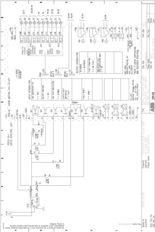
Update Notice |
|
|
|
|
|
|
|
|
|
|
|
|
|
|
|
|
|
|
|
|
|
|
|
|
|
|
|
|
|
|
|
|
|
|
|
|
|
|
|
|
|
|
|
|
|
|
|
|
|
|
|
|
|
|
|
|
|
|
|
|
|
|
|
|
|
|
|
|
|
|
|
|
|
|
|
|
|
|
|
|
|
|
|
|
|
|
|
|
|
|
|
|
|
|
|
|
||||||||||||||
Appendix B Circuit |
|
|
|
|
|
|
|
|
|
|
Page B-4 ADDED: Circuit diagram including the Drive Control Unit |
|||||||||||||||||||||||||||||||||||||||||||||||||||||||||||||||||||||||||||||||||||||||||||||||||||
Diagrams |
|
|
|
|
|
|
|
|
|
|
RDCU |
|||||||||||||||||||||||||||||||||||||||||||||||||||||||||||||||||||||||||||||||||||||||||||||||||||
|
|
|
|
|
|
|
|
|
|
|
|
|
|
|
|
|
|
|
|
|
|
|
|
|
|
|
|
|
|
|
|
|
|
|
|
|
|
|
|
|
|
|
|
|
|
|
|
|
|
|
|
|
|
|
|
|
|
|
|
|
|
|
|
|
|
|
|
|
|
|
|
|
|
|
|
|
|
|
|
|
|
|
|
|
|
|
|
|
|
|
|
|
|
|
|
|
|
|
|
|
|
|
|
|
|
|
|
|
|
|
|
|
|
|
|
|
|
|
|
|
|
|
|
|
|
|
|
|
|
|
|
|
|
|
|
|
|
|
|
|
|
|
|
|
|
|
|
|
|
|
|
|
|
|
|
|
|
|
|
|
|
|
|
|
|
|
|
|
|
|
|
|
|
|
|
|
|
|
|
|
|
|
|
|
|
|
|
|
|
|
|
|
|
|
|
|
|
|
|
|
|
|
|
|
|
|
|
|
|
|
|
|
|
|
|
|
|
|
|
|
|
|
|
|
|
|
|
|
|
|
|
|
|
|
|
|
|
|
|
|
|
|
|
|
|
|
|
|
|
|
|
|
|
|
|
|
|
|
|
|
|
|
|
|
|
|
|
|
|
|
|
|
|
|
|
|
|
|
|
|
|
|
|
|
|
|
|
|
|
|
|
|
|
|
|
|
|
|
|
|
|
|
|
|
|
|
|
|
|
|
|
|
|
|
|
|
|
|
|
|
|
|
|
|
|
|
|
|
|
|
|
|
|
|
|
|
|
|
|
|
|
|
|
|
|
|
|
|
|
|
|
|
|
|
|
|
|
|
|
|
|
|
|
|
|
|
|
|
|
|
|
|
|
|
|
|
|
|
|
|
|
|
|
|
|
|
|
|
|
|
|
|
|
|
|
|
|
|
|
|
|
|
|
|
|
|
|
|
|
|
|
|
|
|
|
|
|
|
|
|
|
|
|
|
|
|
|
|
|
|
|
|
|
|
|
|
|
|
|
|
|
|
|
|
|
|
|
|
|
|
|
|
|
|
|
|
|
|
|
|
|
|
|
|
|
|
|
|
|
|
|
|
|
|
|
|
|
|
|
|
|
|
|
|
|
|
|
|
|
|
|
|
|
|
|
|
|
|
|
|
|
|
|
|
|
|
|
|
|
|
|
|
|
|
|
|
|
|
|
|
|
|
|
|
|
|
|
|
|
|
|
|
|
|
|
|
|
|
|
|
|
|
|
|
|
|
|
|
|
|
|
|
|
|
|
|
|
|
|
|
|
|
|
|
|
|
|
|
|
|
|
|
|
|
|
|
|
|
|
|
|
|
|
|
|
|
|
|
|
|
|
|
|
|
|
|
|
|
|
|
|
|
|
|
|
|
|
|
|
|
|
|
|
|
|
|
|
|
|
|
|
|
|
|
|
|
|
|
|
|
|
|
|
|
|
|
|
|
|
|
|
|
|
|
|
|
|
|
|
|
|
|
|
|
|
|
|
|
|
|
|
|
|
|
|
|
|
|
|
|
|
|
|
|
|
|
|
|
|
|
|
|
|
|
|
|
|
|
|
|
|
|
|
|
|
|
|
|
|
|
|
|
|
|
|
|
|
|
|
|
|
|
|
|
|
|
|
|
|
|
|
|
|
|
|
|
|
|
|
|
|
|
|
|
|
|
|
|
|
|
|
|
|
|
|
|
|
|
|
|
|
|
|
|
|
|
|
|
|
|
|
|
|
|
|
|
|
|
|
|
|
|
|
|
|
|
|
|
|
|
|
|
|
|
|
|
|
|
|
|
|
|
|
|
|
|
|
|
|
|
|
|
|
|
|
|
|
|
|
|
|
|
|
|
|
|
|
|
|
|
|
|
|
|
|
|
|
|
|
|
|
|
|
|
|
|
|
|
|
|
|
|
|
|
|
|
|
|
|
|
|
|
|
|
|
|
|
|
|
|
|
|
|
|
|
|
|
|
|
|
|
|
|
|
|
|
|
|
|
|
|
|
|
|
|
|
|
|
|
|
|
|
|
|
|
|
|
|
|
|
|
|
|
|
|
|
|
|
|
|
|
|
|
|
|
|
|
|
|
|
|
|
|
|
|
|
|
|
|
|
|
|
|
|
|
|
|
|
|
|
|
|
|
|
|
|
|
|
|
|
|
|
|
|
|
|
|
|
|
|
|
|
|
|
|
|
|
|
|
|
|
|
|
|
|
|
|
|
|
|
|
|
|
|
|
|
|
|
|
|
|
|
|
|
|
|
|
|
|
|
|
|
|
|
|
|
|
|
|
|
|
|
|
|
|
|
|
|
|
|
|
|
|
|
|
|
|
|
|
|
|
|
|
|
|
|
|
|
|
|
|
|
|
|
|
|
|
|
|
|
|
|
|
|
|
|
|
|
|
|
|
|
|
|
|
|
|
|
|
|
|
|
|
|
|
|
|
|
|
|
|
|
|
|
|
|
|
|
|
|
|
|
|
|
|
|
|
|
|
|
|
|
|
|
|
|
|
|
|
|
|
|
|
|
|
|
|
|
|
|
|
|
|
|
|
|
|
|
|
|
|
|
|
|
|
|
|
|
|
|
|
|
|
|
|
|
|
|
|
|
|
|
|
|
|
|
|
|
|
|
|
|
|
|
|
|
|
|
|
|
|
|
|
|
|
|
|
|
|
|
|
|
|
|
|
|
|
|
|
|
|
|
|
|
|
|
|
|
|
|
|
|
|
|
|
|
|
|
|
|
|
|
|
|
|
|
|
|
|
|
|
|
|
|
|
|
|
|
|
|
|
|
|
|
|
|
|
|
|
|
|
|
|
|
|
|
|
|
|
|
|
|
|
|
|
|
|
|
|
|
|
|
|
|
|
|
|
|
|
|
|
|
|
|
|
|
|
|
|
|
|
|
|
|
|
|
|
|
|
|
|
|
|
|
|
|
|
|
|
|
|
|
|
|
|
|
|
|
|
|
|
|
|
|
|
|
|
|
|
|
|
|
|
|
|
|
|
|
|
|
|
|
|
|
|
|
|
|
|
|
|
|
|
|
|
|
|
|
|
|
|
|
|
|
|
|
|
|
|
|
|
|
|
|
|
|
|
|
|
|
|
|
|
|
|
|
|
|
|
|
|
|
|
|
|
|
|
|
|
|
|
|
|
|
|
|
|
|
|
|
|
|
|
|
|
|
|
|
|
|
|
|
|
|
|
|
|
|
|
|
|
|
|
|
|
|
|
|
|
|
|
|
|
|
|
|
|
|
|
|
|
|
|
|
|
|
|
|
|
|
|
|
|
|
|
|
|
|
|
|
|
|
|
|
|
|
|
|
|
|
|
|
|
|
|
|
|
|
|
|
|
|
|
|
|
|
|
|
|
|
|
|
|
|
|
|
|
|
|
|
|
|
|
|
|
|
|
|
|
|
|
|
|
|
|
|
|
|
|
|
|
|
|
|
|
|
|
|
|
|
|
|
|
|
|
|
|
|
|
|
|
|
|
|
|
|
|
|
|
|
|
|
|
|
|
|
|
|
|
|
|
|
|
|
|
|
|
|
|
|
|
|
|
|
|
|
|
|
|
|
|
|
|
|
|
|
|
|
|
|
|
|
|
|
|
|
|
|
|
|
|
|
|
|
|
|
|
|
|
|
|
|
|
|
|
|
|
|
|
|
|
|
|
|
|
|
|
|
|
|
|
|
|
|
|
|
|
|
|
|
|
|
|
|
|
|
|
|
|
|
|
|
|
|
|
|
|
|
|
|
|
|
|
|
|
|
|
|
|
|
|
|
|
|
|
|
|
|
|
|
|
|
|
|
|
|
|
|
|
|
|
|
|
|
|
|
|
|
|
|
|
|
|
|
|
|
|
|
|
|
|
|
|
|
|
|
|
|
|
|
|
|
|
|
|
|
|
|
|
|
|
|
|
|
|
|
|
|
|
|
|
|
|
|
|
|
|
|
|
|
|
|
|
|
|
|
|
|
|
|
|
|
|
|
|
|
|
|
|
|
|
|
|
|
|
|
|
|
|
|
|
|
|
|
|
|
|
|
|
|
|
|
|
|
|
|
|
|
|
|
|
|
|
|
|
|
|
|
|
|
|
|
|
|
|
|
|
|
|
|
|
|
|
|
|
|
|
|
|
|
|
|
|
|
|
|
|
|
|
|
|
|
|
|
|
|
|
|
|
|
|
|
|
|
|
|
|
|
|
|
|
|
|
|
|
|
|
|
|
|
|
|
|
|
|
|
|
|
|
|
|
|
|
|
|
|
|
|
|
|
|
|
|
|
|
|
|
|
|
|
|
|
|
|
|
|
|
|
|
|
|
|
|
|
|
|
|
|
|
|
|
|
|
|
|
|
|
|
|
|
|
|
|
|
|
|
|
|
|
|
|
|
|
|
|
|
|
|
|
|
|
|
|
|
|
|
|
|
|
|
|
|
|
|
|
|
|
|
|
|
|
|
|
|
|
|
|
|
|
|
|
|
|
|
|
|
|
|
|
|
|
|
|
|
|
|
|
|
|
|
|
|
|
|
|
|
|
|
|
|
|
|
|
|
|
|
|
|
|
|
|
|
|
|
|
|
|
|
|
|
|
|
|
|
|
|
|
|
|
|
|
|
|
|
|
|
|
|
|
|
|
|
|
|
|
|
|
|
|
|
|
|
|
|
|
|
|
|
|
|
|
|
|
|
|
|
|
|
|
|
|
|
|
|
|
|
|
|
|
|
|
|
|
|
|
|
|
|
|
|
|
|
|
|
|
|
|
|
|
|
|
|
|
|
|
|
|
|
|
|
|
|
|
|
|
|
|
|
|
|
|
|
|
|
|
|
|
|
|
|
|
|
|
|
|
|
|
|
|
|
|
|
|
|
|
|
|
|
|
|
|
|
|
|
|
|
|
|
|
|
|
|
|
|
|
|
|
|
|
|
|
|
|
|
|
|
|
|
|
|
|
|
|
|
|
|
|
|
|
|
|
|
|
|
|
|
|
|
|
|
|
|
|
|
|
|
|
|
|
|
|
|
|
|
|
|
|
|
|
|
|
|
|
|
|
|
|
|
|
|
|
|
|
|
|
|
|
|
|
|
|
|
|
|
|
|
|
|
|
|
|
|
|
|
|
|
|
|
|
|
|
|
|
|
|
|
|
|
|
|
|
|
|
|
|
|
|
|
|
|
|
|
|
|
|
|
|
|
|
|
|
|
|
|
|
|
|
|
|
|
|
|
|
|
|
|
|
|
|
|
|
|
|
|
|
|
|
|
|
|
|
|
|
|
|
|
|
|
|
|
|
|
|
|
|
|
|
|
|
|
|
|
|
|
|
|
|
|
|
|
|
|
|
|
|
|
|
|
|
|
|
|
|
|
|
|
|
|
|
|
|
|
|
|
|
|
|
|
|
|
|
|
|
|
|
|
|
|
|
|
|
|
|
|
|
|
|
|
|
|
|
|
|
|
|
|
|
|
|
|
|
|
|
|
|
|
|
|
|
|
|
|
|
|
|
|
|
|
|
|
|
|
|
|
|
|
|
|
|
|
|
|
|
|
|
|
|
|
|
|
|
|
|
|
|
|
|
|
|
|
|
|
|
|
|
|
|
|
|
|
|
|
|
|
|
|
|
|
|
|
|
|
|
|
|
|
|
|
|
|
|
|
|
|
|
|
|
|
|
|
|
|
|
|
|
|
|
|
|
|
|
|
|
|
|
|
|
|
|
|
|
|
|
|
|
|
|
|
|
|
|
|
|
|
|
|
|
|
|
|
|
|
|
|
|
|
|
|
|
|
|
|
|
|
|
|
|
|
|
|
|
|
|
|
|
|
|
|
|
|
|
|
|
|
|
|
|
|
|
|
|
|
|
|
|
|
|
|
|
|
|
|
|
|
|
|
|
|
|
|
|
|
|
|
|
|
|
|
|
|
|
|
|
|
|
|
|
|
|
|
|
|
|
|
|
|
|
|
|
|
|
|
|
|
|
|
|
|
|
|
|
|
|
|
|
|
|
|
|
|
|
|
|
|
|
|
|
|
|
|
|
|
|
|
|
|
|
|
|
|
|
|
|
|
|
|
|
|
|
|
|
|
|
|
|
|
|
|
|
|
|
|
|
|
|
|
|
|
|
|
|
|
|
|
|
|
|
|
|
|
|
|
|
|
|
|
|
|
|
|
|
|
|
|
|
|
|
|
|
|
|
|
|
|
|
|
|
|
|
|
|
|
|
|
|
|
|
|
|
|
|
|
|
|
|
|
|
|
|
|
|
|
|
|
|
|
|
|
|
|
|
|
|
|
|
|
|
|
|
|
|
|
|
|
|
|
|
|
|
|
|
|
|
|
|
|
|
|
|
|
|
|
|
|
|
|
|
|
|
|
|
|
|
|
|
|
|
|
|
|
|
|
|
|
|
|
|
|
|
|
|
|
|
|
|
|
|
|
|
|
|
|
|
|
|
|
|
|
|
|
|
|
|
|
|
|
|
|
|
|
|
|
|
|
|
|
|
|
|
|
|
|
|
|
|
|
|
|
|
|
|
|
|
|
|
|
|
|
|
|
|
|
|
|
|
|
|
|
|
|
|
|
|
|
|
|
|
|
|
|
|
|
|
|
|
|
|
|
|
|
|
|
|
|
|
|
|
|
|
|
|
|
|
|
|
|
|
|
|
|
|
|
|
|
|
|
|
|
|
|
|
|
|
|
|
|
|
|
|
|
|
|
|
|
|
|
|
|
|
|
|
|
|
|
|
|
|
|
|
|
|
|
|
|
|
|
|
|
|
|
|
|
|
|
|
|
|
|
|
|
|
|
|
|
|
|
|
|
|
|
|
|
|
|
|
|
|
|
|
|
|
|
|
|
|
|
|
|
|
|
|
|
|
|
|
|
|
|
|
|
|
|
|
|
|
|
|
|
|
|
|
|
|
|
|
|
|
|
|
|
|
|
|
|
|
|
|
|
|
|
|
|
|
|
|
|
|
|
|
|
|
|
|
|
|
|
|
|
|
|
|
|
|
|
|
|
|
|
|
|
|
|
|
|
|
|
|
|
|
|
|
|
|
|
|
|
|
|
|
|
|
|
|
|
|
|
|
|
|
|
|
|
|
|
|
|
|
|
|
|
|
|
|
|
|
|
|
|
|
|
|
|
|
|
|
|
|
|
|
|
|
|
|
|
|
|
|
|
|
|
|
|
|
|
|
|
|
|
|
|
|
|
|
|
|
|
|
|
|
|
|
|
|
|
|
|
|
|
|
|
|
|
|
|
|
|
|
|
|
|
|
|
|
|
|
|
|
|
|
|
|
|
|
|
|
|
|
|
|
|
|
|
|
|
|
|
|
|
|
|
|
|
|
|
|
|
|
|
|
|
|
|
|
|
|
|
|
|
|
|
|
|
|
|
|
|
|
|
|
|
|
|
|
|
|
|
|
|
|
|
|
|
|
|
|
|
|
|
|
|
|
|
|
|
|
|
|
|
|
|
|
|
|
|
|
|
|
|
|
|
|
|
|
|
|
|
|
|
|
|
|
|
|
|
|
|
|
|
|
|
|
|
|
|
|
|
|
|
|
|
|
|
|
|
|
|
|
|
|
|
|
|
|
|
|
|
|
|
|
|
|
|
|
|
|
|
|
|
|
|
|
|
|
|
|
|
|
|
|
|
|
|
|
|
|
|
|
|
|
|
|
|
|
|
|
|
|
|
|
|
|
|
|
|
|
|
|
|
|
|
|
|
|
|
|
|
|
|
|
|
|
|
|
|
|
|
|
|
|
|
|
|
|
|
|
|
|
|
|
|
|
|
|
|
|
|
|
|
|
|
|
|
|
|
|
|
|
|
|
|
|
|
|
|
|
|
|
|
|
|
|
|
|
|
|
|
|
|
|
|
|
|
|
|
|
|
|
|
|
|
|
|
|
|
|
|
|
|
|
|
|
|
|
|
|
|
|
|
|
|
|
|
|
|
|
|
|
|
|
|
|
|
|
|
|
|
|
|
|
|
|
|
|
|
|
|
|
|
|
|
|
|
|
|
|
|
|
|
|
|
|
|
|
|
|
|
|
|
|
|
|
|
|
|
|
|
|
|
|
|
|
|
|
|
|
|
|
|
|
|
|
|
|
|
|
|
|
|
|
|
|
|
|
|
|
|
|
|
|
|
|
|
|
|
|
|
|
|
|
|
|
|
|
|
|
|
|
|
|
|
|
|
|
|
|
|
|
|
|
|
|
|
|
|
|
|
|
|
|
|
|
|
|
|
|
|
|
|
|
|
|
|
|
|
|
|
|
|
|
|
|
|
|
|
|
|
|
|
|
|
|
|
|
|
|
|
|
|
|
|
|
|
|
|
|
|
|
|
|
|
|
|
|
|
|
|
|
|
|
|
|
|
|
|
|
|
|
|
|
|
|
|
|
|
|
|
|
|
|
|
|
|
|
|
|
|
|
|
|
|
|
|
|
|
|
|
|
|
|
|
|
|
|
|
|
|
|
|
|
|
|
|
|
|
|
|
|
|
|
|
|
|
|
|
|
|
|
|
|
|
|
|
|
|
|
|
|
|
|
|
|
|
|
|
|
|
|
|
|
|
|
|
|
|
|
|
|
|
|
|
|
|
|
|
|
|
|
|
|
|
|
|
|
|
|
|
|
|
|
|
|
|
|
|
|
|
|
|
|
|
|
|
|
|
|
|
|
|
|
|
|
|
|
|
|
|
|
|
|
|
|
|
|
|
|
|
|
|
|
|
|
|
|
|
|
|
|
|
|
|
|
|
|
|
|
|
|
|
|
|
|
|
|
|
|
|
|
|
|
|
|
|
|
|
|
|
|
|
|
|
|
|
|
|
|
|
|
|
|
|
|
|
|
|
|
|
|
|
|
|
|
|
|
|
|
|
|
|
|
|
|
|
|
|
|
|
|
|
|
|
|
|
|
|
|
|
|
|
|
|
|
|
|
|
|
|
|
|
|
|
|
|
|
|
|
|
|
|
|
|
|
|
|
|
|
|
|
|
|
|
|
|
|
|
|
|
|
|
|
|
|
|
|
|
|
|
|
|
|
|
|
|
|
|
|
|
|
|
|
|
|
|
|
|
|
|
|
|
|
|
|
|
|
|
|
|
|
|
|
|
|
|
|
|
|
|
|
|
|
|
|
|
|
|
|
|
|
|
|
|
|
|
|
|
|
|
|
|
|
|
|
|
|
|
|
|
|
|
|
|
|
|
|
|
|
|
|
|
|
|
|
|
|
|
|
|
|
|
|
|
|
|
|
|
|
|
|
|
|
|
|
|
|
|
|
|
|
|
|
|
|
|
|
|
|
|
|
|
|
|
|
|
|
|
|
|
|
|
|
|
|
|
|
|
|
|
|
|
|
|
|
|
|
|
|
|
|
|
|
|
|
|
|
|
|
|
|
|
|
|
|
|
|
|
|
|
|
|
|
|
|
|
|
|
|
|
|
|
|
|
|
|
|
|
|
|
|
|
|
|
|
|
|
|
|
|
|
|
|
|
|
|
|
|
|
|
|
|
|
|
|
|
|
|
|
|
|
|
|
|
|
|
|
|
|
|
|
|
|
|
|
|
|
|
|
|
|
|
|
|
|
|
|
|
|
|
|
|
|
|
|
|
|
|
|
|
|
|
|
|
|
|
|
|
|
|
|
|
|
|
|
|
|
|
|
|
|
|
|
|
|
|
|
|
|
|
|
|
|
|
|
|
|
|
|
|
|
|
|
|
|
|
|
|
|
|
|
|
|
|
|
|
|
|
|
|
|
|
|
|
|
|
|
|
|
|
|
|
|
|
|
|
|
|
|
|
|
|
|
|
|
|
|
|
|
|
|
|
|
|
|
|
|
|
|
|
|
|
|
|
|
|
|
|
|
|
|
|
|
|
|
|
|
|
|
|
|
|
|
|
|
|
|
|
|
|
|
|
|
|
|
|
|
|
|
|
|
|
|
|
|
|
|
|
|
|
|
|
|
|
|
|
|
|
|
|
|
|
|
|
|
|
|
|
|
|
|
|
|
|
|
|
|
|
|
|
|
|
|
|
|
|
|
|
|
|
|
|
|
|
|
|
|
|
|
|
|
|
|
|
|
|
|
|
|
|
|
|
|
|
|
|
|
|
|
|
|
|
|
|
|
|
|
|
|
|
|
|
|
|
|
|
|
|
|
|
|
|
|
|
|
|
|
|
|
|
|
|
|
|
|
|
|
|
|
|
|
|
|
|
|
|
|
|
|
|
|
|
|
|
|
|
|
|
|
|
|
|
|
|
|
|
|
|
|
|
|
|
|
|
|
|
|
|
|
|
|
|
|
|
|
|
|
|
|
|
|
|
|
|
|
|
|
|
|
|
|
|
|
|
|
|
|
|
|
|
|
|
|
|
|
|
|
|
|
|
|
|
|
|
|
|
|
|
|
|
|
|
|
|
|
|
|
|
|
|
|
|
|
|
|
|
|
|
|
|
|
|
|
|
|
|
|
|
|
|
|
|
|
|
|
|
|
|
|
|
|
|
|
|
|
|
|
|
|
|
|
|
|
|
|
|
|
|
|
|
|
|
|
|
|
|
|
|
|
|
|
|
|
|
|
|
|
|
|
|
|
|
|
|
|
|
|
|
|
|
|
|
|
|
|
|
|
|
|
|
|
|
|
|
|
|
|
|
|
|
|
|
|
|
|
|
|
|
|
|
|
|
|
|
|
|
|
|
|
|
|
|
|
|
|
|
|
|
|
|
|
|
|
|
|
|
|
|
|
|
|
|
|
|
|
|
|
|
|
|
|
|
|
|
|
|
|
|
|
|
|
|
|
|
|
|
|
|
|
|
|
|
|
|
|
|
|
|
|
|
|
|
|
|
|
|
|
|
|
|
|
|
|
|
|
|
|
|
|
|
|
|
|
|
|
|
|
|
|
|
|
|
|
|
|
|
|
|
|
|
|
|
|
|
|
|
|
|
|
|
|
|
|
|
|
|
|
|
|
|
|
|
|
|
|
|
|
|
|
|
|
|
|
|
|
|
|
|
|
|
|
|
|
|
|
|
|
|
|
|
|
|
|
|
|
|
|
|
|
|
|
|
|
|
|
|
|
|
|
|
|
|
|
|
|
|
|
|
|
|
|
|
|
|
|
|
|
|
|
|
|
|
|
|
|
|
|
|
|
|
|
|
|
|
|
|
|
|
|
|
|
|
|
|
|
|
|
|
|
|
|
|
|
|
|
|
|
|
|
|
|
|
|
|
|
|
|
|
|
|
|
|
|
|
|
|
|
|
|
|
|
|
|
|
|
|
|
|
|
|
|
|
|
|
|
|
|
|
|
|
|
|
|
|
|
|
|
|
|
|
|
|
|
|
|
|
|
|
|
|
|
|
|
|
|
|
|
|
|
|
|
|
|
|
|
|
|
|
|
|
|
|
|
|
|
|
|
|
|
|
|
|
|
|
|
|
|
|
|
|
|
|
|
|
|
|
|
|
|
|
|
|
|
|
|
|
|
|
|
|
|
|
|
|
|
|
|
|
|
12 |
Update notice |

Chapter 1 – About this Manual
What this Chapter |
This chapter describes the intended audience and contents of this |
Contains |
manual. It contains a table referring to tasks described in other |
|
manuals. |
Intended Audience |
This manual is intended for people who plan the installation, |
|
commission, use and service the drive equipped with an IGBT supply. |
|
Read the manual before working on the drive. You are expected to |
|
know the fundamentals of electricity, wiring, electrical components and |
|
electrical schematic symbols. |
Parameter Setting |
The parameters of the IGBT Supply Unit (ISU) Program listed in |
|
this manual need not be set in a normal start-up procedure or in |
|
normal use. However, the ISU parameters can be viewed and |
|
changed using the Control Panel. |
To which Products |
This manual applies to the ACA 635 supply sections and ACS 800-17 |
this Manual Applies |
drives which contain the IGBT Supply Unit. |
Contents |
The control program of the IGBT Supply Unit is described in the |
|
following chapters: Chapter 6 – Firmware Description, Chapter 7 – |
|
Fault Tracing and Chapter 8 – Parameters. |
|
Safety Instructions contain installation and maintenance safety |
|
instructions. |
|
Chapter 2 – Operation Basics describes the operation of the IGBT |
|
Supply Unit. |
|
Chapter 3 – Hardware Description describes the hardware of the |
|
ACA 635 supply sections including descriptions of the LCL filter and |
|
the IGBT supply unit which are parts of the ACS 800-17 as well. |
|
Chapter 4 – Commissioning the Supply Section with ISU describes the |
|
commissioning of a supply section that is equipped with the IGBT |
|
Supply Unit (ISU). |
|
Chapter 5 – Earth Fault Protection describes the earth fault protection |
|
solutions available for a drive equipped with an IGBT supply unit. |
|
Appendix A – Technical Data contains technical data for the ACA 635 |
|
giving information on ratings, fuses, cooling requirements, power |
|
losses etc. |
ACA 635 IGBT Supply Sections User’s Manual |
1-1 |

Chapter 1 – About this Manual
|
Appendix B – Circuit Diagrams contains some example circuit |
|
|
diagrams of the ACA 635. |
|
ISU-related |
|
|
Information in Other |
|
|
Manuals |
|
|
|
|
|
Task |
See |
|
|
|
|
Mechanical and Electrical |
ACS 600 MultiDrive Hardware Manual (EN code: 63700118) or ACS800-17 Hardware |
|
Installation of the Drive |
Manual (EN code: 64638505) |
|
Installation of Optional Modules |
|
|
and DriveWindow |
|
|
Preventive Maintenance |
|
|
|
|
|
Technical Data for the |
ACS800-17 Hardware Manual (EN code: 64638505) |
|
ACS 800-17 |
|
|
|
|
|
Associating ISU with |
DriveWindow Start-up Guide (EN code: 36458585) |
|
DriveWindow |
When associating DriveWindow 1.3 and 1.4 with the ISU proceed as follows: |
|
|
||
|
|
|
|
System Configuration Messages |
What to do |
|
|
|
|
Error: Encountered target ‘ISU600-xxxx-x’ is unknown. |
Click OK. |
|
Do you wish to associate it? |
|
|
|
|
|
Associate ‘ISU600-xxxx-x’ With |
Choose ACS600 MultiDrive |
|
|
from the list. |
|
|
|
|
Do you wish association ‘ISU600-xxxx-x’ = ACS600 |
Click Yes. |
|
MultiDrive be permanent? |
|
|
|
|
|
|
|
User Interface |
Firmware Manual (for System, Standard or Crane Drive Application Program) |
|
|
The user interface of the IGBT Supply Unit is a CDP 312 Control Panel or a PC, which |
|
|
is equipped with a DDCS board and DriveWindow. |
|
|
|
|
1-2 |
ACA 635 IGBT Supply Sections User’s Manual |
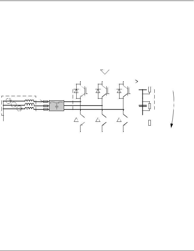
Chapter 2 – Operation Basics
Operation of ISU |
The ISU is a four-quadrant switching-mode converter, i.e., the power |
||||||||||||||||||||||||||||||||||||||||||||
|
flow through the converter is reversible. The AC current of the ISU is |
||||||||||||||||||||||||||||||||||||||||||||
|
sinusoidal at a unity power factor. As a default, the ISU controls the DC |
||||||||||||||||||||||||||||||||||||||||||||
|
link voltage to the peak value of the line-to-line voltage. The DC voltage |
||||||||||||||||||||||||||||||||||||||||||||
|
reference can be set also higher by a parameter. |
||||||||||||||||||||||||||||||||||||||||||||
Main Circuit Diagram |
A diagram of the main circuit of the IGBT supply is shown below. |
||||||||||||||||||||||||||||||||||||||||||||
|
|
|
|
|
|
|
|
|
|
|
|
|
|
|
|
|
|
|
|
|
|
|
|
|
|
|
|
|
|
|
|
|
|
|
|
|
|
|
|
||||||
|
|
|
|
|
|
|
Control and Gate Drivers |
|
|
|
|
|
|
|
|
|
|
|
|
|
|
|
|
||||||||||||||||||||||
|
|
|
|
|
|
|
|
|
|
|
|
|
|
|
|
|
|
|
|
|
|
|
|
|
|
|
|
|
|
|
|
|
|
|
|
|
|
|
|
|
|
Common DC bus |
|||
|
|
|
|
|
|
|
|
|
|
|
|
|
|
|
|
|
|
|
|
|
|
|
|
|
|
|
|
|
|
|
|
|
|
|
|
|
|
|
|
|
|
||||
|
|
|
|
|
|
|
|
|
|
|
|
|
|
|
|
|
|
|
|
|
|
|
|
|
|
|
|
|
|
|
|
|
|
|
|
|
|||||||||
|
|
|
|
|
|
|
|
|
|
|
|
|
|
|
|
|
|
|
|
|
|
|
|
|
Idc |
|
|
|
|
|
|
||||||||||||||
|
|
|
|
|
|
|
|
|
|
|
|
|
|
|
|
|
|
|
|
|
|
|
|
|
|||||||||||||||||||||
|
|
|
|
|
|
|
|
|
|
|
|
|
|
|
|
|
|
|
|
|
|
|
|
|
|
|
|
|
|
|
|
||||||||||||||
|
|
|
|
|
|
|
|
|
|
|
|
|
|
|
|
|
|
|
|
|
|
|
|
|
|
|
|
|
|
|
|
|
|
|
|
|
|
|
|
|
|
|
|
|
|
|
|
|
|
|
|
|
|
|
|
|
|
|
|
|
|
|
|
|
|
|
|
|
|
|
|
|
|
|
|
|
|
|
|
|
|
|
|
|
|
|
|
|
|
|
|
Supply network
IU |
LCL Filter |
Uc
|
|
|
|
|
|
|
|
|
|
|
|
|
|
|
|
|
|
|
|
|
|
|
|
|
|
|
|
|
|
|
|
|
|
|
|
|
|
|
|
|
|
|
|
|
|
|
|
|
|
|
|
|
|
|
|
|
|
|
|
|
|
|
|
|
|
|
|
|
|
|
|
|
|
|
|
|
|
|
|
|
|
|
|
|
|
|
|
|
|
|
|
|
|
|
|
|
|
|
|
|
|
|
|
|
|
|
|
|
|
|
|
|
|
|
|
|
|
|
|
|
|
|
|
|
|
|
|
|
|
|
|
|
|
|
|
|
|
|
|
|
|
|
|
|
|
|
|
|
|
|
|
|
|
|
|
|
|
|
|
|
|
|
|
|
|
|
|
|
|
|
|
|
|
|
|
|
|
|
|
|
|
|
|
|
|
|
|
|
|
|
|
|
|
|
|
|
|
|
|
|
|
|
|
|
|
|
|
|
|
|
|
|
|
|
|
|
|
|
|
|
|
|
|
|
|
|
|
|
|
|
|
|
|
|
|
|
|
|
|
|
|
|
|
|
|
|
|
|
|
|
|
|
|
|
|
|
|
|
|
|
|
|
|
|
|
|
|
|
|
|
|
|
|
|
|
|
|
|
|
|
|
|
|
|
|
|
|
|
|
|
|
|
|
|
|
|
|
|
|
|
|
|
|
|
|
|
|
|
|
|
|
|
|
|
|
|
|
|
|
|
|
|
|
|
|
|
|
|
|
|
|
|
|
|
|
|
|
|
|
|
|
|
|
|
|
|
|
|
|
|
|
|
|
|
|
|
|
|
|
|
|
|
|
|
|
|
|
|
|
|
|
|
|
|
|
|
|
|
|
|
|
|
|
|
|
|
|
|
|
|
|
|
|
|
|
|
|
|
|
|
|
|
|
|
|
|
|
|
|
|
|
|
|
|
|
|
|
|
|
|
|
|
|
|
|
|
|
|
|
|
|
|
|
|
|
|
|
|
|
|
|
|
|
|
|
|
|
|
|
|
|
|
|
|
|
|
|
|
|
|
|
|
|
|
|
|
|
|
|
|
|
|
|
|
|
|
|
|
|
|
|
|
|
|
|
|
|
|
|
|
|
|
|
|
|
|
|
|
|
|
|
|
|
|
|
|
|
|
|
|
|
|
|
|
|
|
|
|
|
|
|
|
|
|
|
|
|
|
|
|
|
|
|
|
|
|
|
|
|
|
|
|
|
|
|
|
|
|
|
|
|
|
|
|
|
|
|
|
|
|
|
|
|
|
|
|
|
|
|
|
|
|
|
|
|
|
|
|
|
|
|
|
|
|
|
Converter |
||||||||||||||||||||||||||||||||||
Control |
|
The control and modulation is based on the Direct Torque Control |
||||||||||||||||||||||||||||||||||||||||||||||||||||||||||||||||||
|
|
|
|
|
|
|
|
|
|
|
|
|
|
|
|
|
|
|
(DTC) method typically used in ACS 600 motor control. Two line |
|||||||||||||||||||||||||||||||||||||||||||||||||
|
|
|
|
|
|
|
|
|
|
|
|
|
|
|
|
|
|
|
currents and DC link voltage are measured and used for the control. |
|||||||||||||||||||||||||||||||||||||||||||||||||
|
|
|
|
|
|
|
|
|
|
|
|
|
|
|
|
|
|
|
The control boards are similar to the boards of the inverter. |
|||||||||||||||||||||||||||||||||||||||||||||||||
ACA 635 IGBT Supply Sections, ACS800-17 |
2-1 |
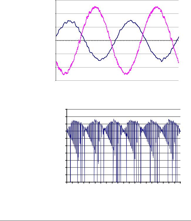
Chapter 2 – Operation Basics
Voltage and Current
Waveforms
The high frequency switching and high du/dt slightly distorts the voltage waveform at the input of the converter. The depth of the voltage notches depends on the ratio of network inductance to total line inductance (network + LCL filter inductance).
Typical line current (iU) and voltage (uUV) waveforms are shown below.
(A, V)
1200 |
|
|
|
|
|
|
|
|
|
|
|
|
|
|
|
|
|
|
|
|
|
|
|
|
uUV |
|
|
|
|
|
|
|
|
|
|
|
|
|
|
800 |
|
|
|
|
|
|
|
|
|
|
|
|
|
|
|
|
|
|
|
|
|
iU |
|
|
|
|
|
|
|
|
|
|
|
|
|
|
|
|
|
400 |
|
|
|
|
|
|
|
|
|
|
|
|
|
|
|
|
|
|
|
0 |
2 |
4 |
6 |
8 |
10 |
12 |
14 |
16 |
18 |
20 |
22 |
24 |
26 |
28 |
30 |
32 |
34 |
36 |
t (ms) |
0 |
38 |
||||||||||||||||||
-400 |
|
|
|
|
|
|
|
|
|
|
|
|
|
|
|
|
|
|
|
-800 |
|
|
|
|
|
|
|
|
|
|
|
|
|
|
|
|
|
|
|
-1200 |
|
|
|
|
|
|
|
|
|
|
|
|
|
|
|
|
|
|
|
DC Current A typical DC current (idc) waveform is shown below.
(A) |
|
|
|
|
|
|
|
|
|
|
500 |
|
idc |
|
|
|
|
|
|
|
|
450 |
|
|
|
|
|
|
|
|
|
|
|
|
|
|
|
|
|
|
|
|
|
400 |
|
|
|
|
|
|
|
|
|
|
350 |
|
|
|
|
|
|
|
|
|
|
300 |
|
|
|
|
|
|
|
|
|
|
250 |
|
|
|
|
|
|
|
|
|
|
200 |
|
|
|
|
|
|
|
|
|
|
150 |
|
|
|
|
|
|
|
|
|
|
100 |
|
|
|
|
|
|
|
|
|
|
50 |
|
|
|
|
|
|
|
|
|
|
0 |
|
|
|
|
|
|
|
|
|
|
100 |
102 |
104 |
106 |
108 |
110 |
112 |
114 |
116 |
118 |
t (ms) |
2-2 |
ACA 635 IGBT Supply Sections, ACS800-17 |
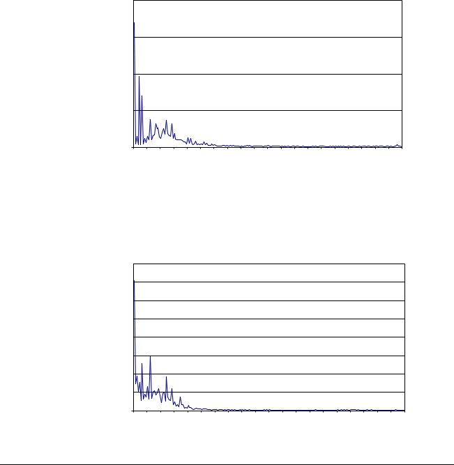
|
Chapter 2 – Operation Basics |
Distortion |
IGBT supply unit does not generate characteristic current/voltage |
|
overtones llike a traditional 6- or 12-pulse bridge does, because of the |
|
sinusoidal waveform of the line current. The Total Harmonic Distortion |
|
(THD) in voltage depends slightly on the Short Circuit Ratio in the Point |
|
of Common Coupling (PCC), refer to Appendix A – Technical Data. |
Spectrum of the Voltage A typical spectrum of the voltage distortion at the output of the DIstortion transformer is shown below. Each harmonic is presented as a
percentage of the fundamental voltage. n denotes the ordinal number of the harmonic.
2 |
|
|
|
|
|
|
|
|
|
|
|
|
|
|
|
|
|
|
|
1,5 |
|
|
|
|
|
|
|
|
|
|
|
|
|
|
|
|
|
|
|
1 |
|
|
|
|
|
|
|
|
|
|
|
|
|
|
|
|
|
|
|
0,5 |
|
|
|
|
|
|
|
|
|
|
|
|
|
|
|
|
|
|
|
0 |
|
|
|
|
|
|
|
|
|
|
|
|
|
|
|
|
|
|
|
THD |
11 |
21 |
31 |
41 |
51 |
61 |
71 |
81 |
91 |
101 |
111 |
121 |
131 |
141 |
151 |
161 |
171 |
181 |
191 |
Spectrum of the Line A typical spectrum of the line current distortion is shown below. Each Current Distortion harmonic is presented as a percentage of the fundamental current. n
denotes the ordinal number of the harmonic.
4 |
|
|
|
|
|
|
|
|
|
|
|
|
|
|
|
|
|
|
|
3,5 |
|
|
|
|
|
|
|
|
|
|
|
|
|
|
|
|
|
|
|
3 |
|
|
|
|
|
|
|
|
|
|
|
|
|
|
|
|
|
|
|
2,5 |
|
|
|
|
|
|
|
|
|
|
|
|
|
|
|
|
|
|
|
2 |
|
|
|
|
|
|
|
|
|
|
|
|
|
|
|
|
|
|
|
1,5 |
|
|
|
|
|
|
|
|
|
|
|
|
|
|
|
|
|
|
|
1 |
|
|
|
|
|
|
|
|
|
|
|
|
|
|
|
|
|
|
|
0,5 |
|
|
|
|
|
|
|
|
|
|
|
|
|
|
|
|
|
|
|
0 |
|
|
|
|
|
|
|
|
|
|
|
|
|
|
|
|
|
|
|
THD |
11 |
21 |
31 |
41 |
51 |
61 |
71 |
81 |
91 |
101 |
111 |
121 |
131 |
141 |
151 |
161 |
171 |
181 |
191 |
ACA 635 IGBT Supply Sections, ACS800-17 |
2-3 |

Chapter 2 – Operation Basics
2-4 |
ACA 635 IGBT Supply Sections, ACS800-17 |
 Loading...