


 Loading...
ABB drives
User’s manual
ACS320 drives (0.5 to 30 hp)
List of related manuals
Drive manuals |
Code (English) |
ACS320 drives (0.5 to 30 hp) user’s manual |
3AUA0000062599 |
ACS320 Short Form User’s Manual |
3AUA0000086933 |
Option manuals and guides |
|
MFDT-01 FlashDrop user’s manual |
3AFE68591074 |
MREL-01 output relay module user’s manual |
3AUA0000035974 |
MUL1-R1 installation instructions for ACS150, ACS310, 3AFE68642868 ACS320, ACS350 and ACS355
MUL1-R3 installation instructions for ACS310, ACS320, 3AFE68643147 ACS350 and ACS355
MUL1-R4 installation instructions for ACS310, ACS320, 3AUA0000025916 ACS350 and ACS355
SREA-01 |
Ethernet adapter module quick start-up guide 3AUA0000042902 |
|
SREA-01 |
Ethernet adapter module user’s manual |
3AUA0000042896 |
Maintenance manuals |
|
|
Guide for capacitor reforming in ACS50, ACS55, |
3AFE68735190 |
|
ACS150, ACS310, ACS350, ACS355, ACS550, |
|
|
ACH550 and R1-R4 OINT-/SINT-boards |
|
|
You can find manuals and other product documents in PDF format on the Internet. See section Document library on the Internet on the inside of the back cover. For manuals not available in the Document library, contact your local ABB representative.
User’s manual
ACS320 drives (0.5 to 30 hp)
Table of contents
1. Safety
4. Mechanical installation
6. Electrical installation
8. Start-up
Index
2016 ABB Oy. All Rights Reserved. |
3AUA0000062599 Rev E |
|
EN |
|
EFFECTIVE: 2016-07-05 |

Table of contents 5
Table of contents
List of related manuals . . . . . . . . . . . . . . . . . . . . . . . . . . . . . . . . . . . . . . . . . . . . . . . . . . . . . . . |
2 |
1. Safety
Contents of this chapter . . . . . . . . . . . . . . . . . . . . . . . . . . . . . . . . . . . . . . . . . . . . . . . . . . . . . . 15 Use of warning symbols . . . . . . . . . . . . . . . . . . . . . . . . . . . . . . . . . . . . . . . . . . . . . . . . . . . . . 15 Safety in installation and maintenance . . . . . . . . . . . . . . . . . . . . . . . . . . . . . . . . . . . . . . . . . . 16 Electrical safety . . . . . . . . . . . . . . . . . . . . . . . . . . . . . . . . . . . . . . . . . . . . . . . . . . . . . . . . . 16 General safety . . . . . . . . . . . . . . . . . . . . . . . . . . . . . . . . . . . . . . . . . . . . . . . . . . . . . . . . . . 17 Safe start-up and operation . . . . . . . . . . . . . . . . . . . . . . . . . . . . . . . . . . . . . . . . . . . . . . . . . . . 17 General safety . . . . . . . . . . . . . . . . . . . . . . . . . . . . . . . . . . . . . . . . . . . . . . . . . . . . . . . . . . 17
2. Introduction to the manual
Contents of this chapter . . . . . . . . . . . . . . . . . . . . . . . . . . . . . . . . . . . . . . . . . . . . . . . . . . . . . . 19 Applicability . . . . . . . . . . . . . . . . . . . . . . . . . . . . . . . . . . . . . . . . . . . . . . . . . . . . . . . . . . . . . . . 19 Target audience . . . . . . . . . . . . . . . . . . . . . . . . . . . . . . . . . . . . . . . . . . . . . . . . . . . . . . . . . . . . 19 Purpose of the manual . . . . . . . . . . . . . . . . . . . . . . . . . . . . . . . . . . . . . . . . . . . . . . . . . . . . . . 19 Contents of this manual . . . . . . . . . . . . . . . . . . . . . . . . . . . . . . . . . . . . . . . . . . . . . . . . . . . . . . 20 Related documents . . . . . . . . . . . . . . . . . . . . . . . . . . . . . . . . . . . . . . . . . . . . . . . . . . . . . . . . . 21 Categorization by frame size . . . . . . . . . . . . . . . . . . . . . . . . . . . . . . . . . . . . . . . . . . . . . . . . . . 21 Quick installation and commissioning flowchart . . . . . . . . . . . . . . . . . . . . . . . . . . . . . . . . . . . 22
3. Operation principle and hardware description
Contents of this chapter . . . . . . . . . . . . . . . . . . . . . . . . . . . . . . . . . . . . . . . . . . . . . . . . . . . . . . 23 Operation principle . . . . . . . . . . . . . . . . . . . . . . . . . . . . . . . . . . . . . . . . . . . . . . . . . . . . . . . . . 23 Product overview . . . . . . . . . . . . . . . . . . . . . . . . . . . . . . . . . . . . . . . . . . . . . . . . . . . . . . . . . . . 24 Layout . . . . . . . . . . . . . . . . . . . . . . . . . . . . . . . . . . . . . . . . . . . . . . . . . . . . . . . . . . . . . . . . 24 Power connections and control interfaces . . . . . . . . . . . . . . . . . . . . . . . . . . . . . . . . . . . . 25 Type designation label . . . . . . . . . . . . . . . . . . . . . . . . . . . . . . . . . . . . . . . . . . . . . . . . . . . . . . . 26 Type designation key . . . . . . . . . . . . . . . . . . . . . . . . . . . . . . . . . . . . . . . . . . . . . . . . . . . . . . . . 27
4. Mechanical installation
Contents of this chapter . . . . . . . . . . . . . . . . . . . . . . . . . . . . . . . . . . . . . . . . . . . . . . . . . . . . . . 29 Checking the installation site . . . . . . . . . . . . . . . . . . . . . . . . . . . . . . . . . . . . . . . . . . . . . . . . . . 29 Requirements for the installation site . . . . . . . . . . . . . . . . . . . . . . . . . . . . . . . . . . . . . . . . 29 Required tools . . . . . . . . . . . . . . . . . . . . . . . . . . . . . . . . . . . . . . . . . . . . . . . . . . . . . . . . . . . . . 30 Unpacking . . . . . . . . . . . . . . . . . . . . . . . . . . . . . . . . . . . . . . . . . . . . . . . . . . . . . . . . . . . . . . . . 31 Checking the delivery . . . . . . . . . . . . . . . . . . . . . . . . . . . . . . . . . . . . . . . . . . . . . . . . . . . . . . . 31 Installing . . . . . . . . . . . . . . . . . . . . . . . . . . . . . . . . . . . . . . . . . . . . . . . . . . . . . . . . . . . . . . . . . 32 Install the drive . . . . . . . . . . . . . . . . . . . . . . . . . . . . . . . . . . . . . . . . . . . . . . . . . . . . . . . . . 32 Fasten clamping plates . . . . . . . . . . . . . . . . . . . . . . . . . . . . . . . . . . . . . . . . . . . . . . . . . . . 34
5. Planning the electrical installation
Contents of this chapter . . . . . . . . . . . . . . . . . . . . . . . . . . . . . . . . . . . . . . . . . . . . . . . . . . . . . . 35

6 Table of contents |
|
Implementing the AC power line connection . . . . . . . . . . . . . . . . . . . . . . . . . . . . . . . . . . . . . |
35 |
Selecting the supply disconnecting device (disconnecting means) . . . . . . . . . . . . . . . . . . . . |
36 |
European union . . . . . . . . . . . . . . . . . . . . . . . . . . . . . . . . . . . . . . . . . . . . . . . . . . . . . . . . |
36 |
North America . . . . . . . . . . . . . . . . . . . . . . . . . . . . . . . . . . . . . . . . . . . . . . . . . . . . . . . . . |
36 |
Other regions . . . . . . . . . . . . . . . . . . . . . . . . . . . . . . . . . . . . . . . . . . . . . . . . . . . . . . . . . . |
36 |
Checking the compatibility of the motor and drive . . . . . . . . . . . . . . . . . . . . . . . . . . . . . . . . . |
36 |
Selecting the power cables . . . . . . . . . . . . . . . . . . . . . . . . . . . . . . . . . . . . . . . . . . . . . . . . . . |
37 |
General rules . . . . . . . . . . . . . . . . . . . . . . . . . . . . . . . . . . . . . . . . . . . . . . . . . . . . . . . . . . |
37 |
Alternative power cable types . . . . . . . . . . . . . . . . . . . . . . . . . . . . . . . . . . . . . . . . . . . . . |
38 |
Motor cable shield . . . . . . . . . . . . . . . . . . . . . . . . . . . . . . . . . . . . . . . . . . . . . . . . . . . . . . |
38 |
Additional North American requirements . . . . . . . . . . . . . . . . . . . . . . . . . . . . . . . . . . . . . |
39 |
Selecting the control cables . . . . . . . . . . . . . . . . . . . . . . . . . . . . . . . . . . . . . . . . . . . . . . . . . . |
40 |
General rules . . . . . . . . . . . . . . . . . . . . . . . . . . . . . . . . . . . . . . . . . . . . . . . . . . . . . . . . . . |
40 |
Relay cable . . . . . . . . . . . . . . . . . . . . . . . . . . . . . . . . . . . . . . . . . . . . . . . . . . . . . . . . . . . |
40 |
Control panel cable . . . . . . . . . . . . . . . . . . . . . . . . . . . . . . . . . . . . . . . . . . . . . . . . . . . . . |
40 |
Routing the cables . . . . . . . . . . . . . . . . . . . . . . . . . . . . . . . . . . . . . . . . . . . . . . . . . . . . . . . . . |
41 |
Control cable ducts . . . . . . . . . . . . . . . . . . . . . . . . . . . . . . . . . . . . . . . . . . . . . . . . . . . . . |
41 |
Protecting the drive, input power cable, motor and motor cable in short circuit situations and |
|
against thermal overload . . . . . . . . . . . . . . . . . . . . . . . . . . . . . . . . . . . . . . . . . . . . . . . . . . . . |
42 |
Protecting the drive and input power cable in short-circuit situations . . . . . . . . . . . . . . . |
42 |
Protecting the motor and motor cable in short-circuit situations . . . . . . . . . . . . . . . . . . . |
42 |
Protecting the motor against thermal overload . . . . . . . . . . . . . . . . . . . . . . . . . . . . . . . . |
42 |
Using residual current devices (RCD) with the drive . . . . . . . . . . . . . . . . . . . . . . . . . . . . . . . |
43 |
Implementing a bypass connection . . . . . . . . . . . . . . . . . . . . . . . . . . . . . . . . . . . . . . . . . . . . |
43 |
Protecting the contacts of relay outputs . . . . . . . . . . . . . . . . . . . . . . . . . . . . . . . . . . . . . . . . . |
44 |
6. Electrical installation |
|
Contents of this chapter . . . . . . . . . . . . . . . . . . . . . . . . . . . . . . . . . . . . . . . . . . . . . . . . . . . . . |
45 |
Checking the insulation of the assembly . . . . . . . . . . . . . . . . . . . . . . . . . . . . . . . . . . . . . . . . |
45 |
Drive . . . . . . . . . . . . . . . . . . . . . . . . . . . . . . . . . . . . . . . . . . . . . . . . . . . . . . . . . . . . . . . . . |
45 |
Input power cable . . . . . . . . . . . . . . . . . . . . . . . . . . . . . . . . . . . . . . . . . . . . . . . . . . . . . . . |
45 |
Motor and motor cable . . . . . . . . . . . . . . . . . . . . . . . . . . . . . . . . . . . . . . . . . . . . . . . . . . . |
46 |
Checking the compatibility with IT (ungrounded) and corner grounded TN systems . . . . . . . |
47 |
Connecting the power cables . . . . . . . . . . . . . . . . . . . . . . . . . . . . . . . . . . . . . . . . . . . . . . . . . |
48 |
Connection diagram . . . . . . . . . . . . . . . . . . . . . . . . . . . . . . . . . . . . . . . . . . . . . . . . . . . . . |
48 |
Connection procedure . . . . . . . . . . . . . . . . . . . . . . . . . . . . . . . . . . . . . . . . . . . . . . . . . . . |
49 |
Connecting the control cables . . . . . . . . . . . . . . . . . . . . . . . . . . . . . . . . . . . . . . . . . . . . . . . . |
50 |
I/O terminals . . . . . . . . . . . . . . . . . . . . . . . . . . . . . . . . . . . . . . . . . . . . . . . . . . . . . . . . . . . |
50 |
Default I/O connection diagram . . . . . . . . . . . . . . . . . . . . . . . . . . . . . . . . . . . . . . . . . . . . |
53 |
Connection procedure . . . . . . . . . . . . . . . . . . . . . . . . . . . . . . . . . . . . . . . . . . . . . . . . . . . |
54 |
Connecting the embedded fieldbus . . . . . . . . . . . . . . . . . . . . . . . . . . . . . . . . . . . . . . . . . . . . |
55 |
Connection diagram . . . . . . . . . . . . . . . . . . . . . . . . . . . . . . . . . . . . . . . . . . . . . . . . . . . . . |
55 |
7. Installation checklist |
|
Contents of this chapter . . . . . . . . . . . . . . . . . . . . . . . . . . . . . . . . . . . . . . . . . . . . . . . . . . . . . |
57 |
Checking the installation . . . . . . . . . . . . . . . . . . . . . . . . . . . . . . . . . . . . . . . . . . . . . . . . . . . . |
57 |

Table of contents 7
8. Start-up
Contents of this chapter . . . . . . . . . . . . . . . . . . . . . . . . . . . . . . . . . . . . . . . . . . . . . . . . . . . . . . 59 HVAC control panel features . . . . . . . . . . . . . . . . . . . . . . . . . . . . . . . . . . . . . . . . . . . . . . . . . . 59 General display features . . . . . . . . . . . . . . . . . . . . . . . . . . . . . . . . . . . . . . . . . . . . . . . . . . 60 Start-up . . . . . . . . . . . . . . . . . . . . . . . . . . . . . . . . . . . . . . . . . . . . . . . . . . . . . . . . . . . . . . . . . . 62 Start-up by using the Start-up assistant . . . . . . . . . . . . . . . . . . . . . . . . . . . . . . . . . . . . . . 62 Start-up by changing the parameters individually . . . . . . . . . . . . . . . . . . . . . . . . . . . . . . . 63 Modes . . . . . . . . . . . . . . . . . . . . . . . . . . . . . . . . . . . . . . . . . . . . . . . . . . . . . . . . . . . . . . . . . . . 64 Standard display mode . . . . . . . . . . . . . . . . . . . . . . . . . . . . . . . . . . . . . . . . . . . . . . . . . . . 64 Parameters mode . . . . . . . . . . . . . . . . . . . . . . . . . . . . . . . . . . . . . . . . . . . . . . . . . . . . . . . 66 Start-up assistant mode . . . . . . . . . . . . . . . . . . . . . . . . . . . . . . . . . . . . . . . . . . . . . . . . . . 68 Changed parameters mode . . . . . . . . . . . . . . . . . . . . . . . . . . . . . . . . . . . . . . . . . . . . . . . 70 Fault logger mode . . . . . . . . . . . . . . . . . . . . . . . . . . . . . . . . . . . . . . . . . . . . . . . . . . . . . . . 70 Drive parameter backup mode . . . . . . . . . . . . . . . . . . . . . . . . . . . . . . . . . . . . . . . . . . . . . 70 Clock set mode . . . . . . . . . . . . . . . . . . . . . . . . . . . . . . . . . . . . . . . . . . . . . . . . . . . . . . . . . 75 I/O settings mode . . . . . . . . . . . . . . . . . . . . . . . . . . . . . . . . . . . . . . . . . . . . . . . . . . . . . . . 78
9. Application macros |
|
Contents of this chapter . . . . . . . . . . . . . . . . . . . . . . . . . . . . . . . . . . . . . . . . . . . . . . . . . . . . . . |
79 |
Overview of macros . . . . . . . . . . . . . . . . . . . . . . . . . . . . . . . . . . . . . . . . . . . . . . . . . . . . . . . . . |
79 |
General considerations . . . . . . . . . . . . . . . . . . . . . . . . . . . . . . . . . . . . . . . . . . . . . . . . . . . . . . |
80 |
Selecting an application macro . . . . . . . . . . . . . . . . . . . . . . . . . . . . . . . . . . . . . . . . . . . . . . . . |
81 |
Restoring defaults . . . . . . . . . . . . . . . . . . . . . . . . . . . . . . . . . . . . . . . . . . . . . . . . . . . . . . . . . . |
81 |
Control wiring . . . . . . . . . . . . . . . . . . . . . . . . . . . . . . . . . . . . . . . . . . . . . . . . . . . . . . . . . . . . . . |
81 |
Application / Macro listing . . . . . . . . . . . . . . . . . . . . . . . . . . . . . . . . . . . . . . . . . . . . . . . . . . . . |
82 |
HVAC default . . . . . . . . . . . . . . . . . . . . . . . . . . . . . . . . . . . . . . . . . . . . . . . . . . . . . . . . . . |
83 |
Supply fan . . . . . . . . . . . . . . . . . . . . . . . . . . . . . . . . . . . . . . . . . . . . . . . . . . . . . . . . . . . . . |
84 |
Return fan . . . . . . . . . . . . . . . . . . . . . . . . . . . . . . . . . . . . . . . . . . . . . . . . . . . . . . . . . . . . . |
85 |
Cooling tower fan . . . . . . . . . . . . . . . . . . . . . . . . . . . . . . . . . . . . . . . . . . . . . . . . . . . . . . . |
86 |
Condenser . . . . . . . . . . . . . . . . . . . . . . . . . . . . . . . . . . . . . . . . . . . . . . . . . . . . . . . . . . . . . |
87 |
Booster pump . . . . . . . . . . . . . . . . . . . . . . . . . . . . . . . . . . . . . . . . . . . . . . . . . . . . . . . . . . |
88 |
PFA control macro . . . . . . . . . . . . . . . . . . . . . . . . . . . . . . . . . . . . . . . . . . . . . . . . . . . . . . |
89 |
Internal timer . . . . . . . . . . . . . . . . . . . . . . . . . . . . . . . . . . . . . . . . . . . . . . . . . . . . . . . . . . . |
90 |
Internal timer with constant speeds / PRV . . . . . . . . . . . . . . . . . . . . . . . . . . . . . . . . . . . . |
91 |
Floating point . . . . . . . . . . . . . . . . . . . . . . . . . . . . . . . . . . . . . . . . . . . . . . . . . . . . . . . . . . . |
92 |
Dual setpoint with PID . . . . . . . . . . . . . . . . . . . . . . . . . . . . . . . . . . . . . . . . . . . . . . . . . . . . |
93 |
Dual setpoint with PID and constant speeds . . . . . . . . . . . . . . . . . . . . . . . . . . . . . . . . . . . |
94 |
E-BYPASS . . . . . . . . . . . . . . . . . . . . . . . . . . . . . . . . . . . . . . . . . . . . . . . . . . . . . . . . . . . . |
95 |
Hand control . . . . . . . . . . . . . . . . . . . . . . . . . . . . . . . . . . . . . . . . . . . . . . . . . . . . . . . . . . . |
96 |
E-Clipse . . . . . . . . . . . . . . . . . . . . . . . . . . . . . . . . . . . . . . . . . . . . . . . . . . . . . . . . . . . . . . . |
97 |
Modbus configuration macro . . . . . . . . . . . . . . . . . . . . . . . . . . . . . . . . . . . . . . . . . . . . . . . |
98 |
10. Program features
Contents of this chapter . . . . . . . . . . . . . . . . . . . . . . . . . . . . . . . . . . . . . . . . . . . . . . . . . . . . . . 99 Start-up assistant . . . . . . . . . . . . . . . . . . . . . . . . . . . . . . . . . . . . . . . . . . . . . . . . . . . . . . . . . . . 99 Introduction . . . . . . . . . . . . . . . . . . . . . . . . . . . . . . . . . . . . . . . . . . . . . . . . . . . . . . . . . . . . 99 List of the tasks and the relevant drive parameters . . . . . . . . . . . . . . . . . . . . . . . . . . . . 100 Contents of the assistant displays . . . . . . . . . . . . . . . . . . . . . . . . . . . . . . . . . . . . . . . . . . 101

8 Table of contents
Local control vs. external control . . . . . . . . . . . . . . . . . . . . . . . . . . . . . . . . . . . . . . . . . . . . . 102 Local control . . . . . . . . . . . . . . . . . . . . . . . . . . . . . . . . . . . . . . . . . . . . . . . . . . . . . . . . . . 102 External control . . . . . . . . . . . . . . . . . . . . . . . . . . . . . . . . . . . . . . . . . . . . . . . . . . . . . . . 103 Settings . . . . . . . . . . . . . . . . . . . . . . . . . . . . . . . . . . . . . . . . . . . . . . . . . . . . . . . . . . . . . 103 Diagnostics . . . . . . . . . . . . . . . . . . . . . . . . . . . . . . . . . . . . . . . . . . . . . . . . . . . . . . . . . . . 103 Block diagram: Start, stop, direction source for EXT1 . . . . . . . . . . . . . . . . . . . . . . . . . . 104 Block diagram: Reference source for EXT1 . . . . . . . . . . . . . . . . . . . . . . . . . . . . . . . . . . 104
Reference types and processing . . . . . . . . . . . . . . . . . . . . . . . . . . . . . . . . . . . . . . . . . . . . . 105 Settings . . . . . . . . . . . . . . . . . . . . . . . . . . . . . . . . . . . . . . . . . . . . . . . . . . . . . . . . . . . . . 105 Diagnostics . . . . . . . . . . . . . . . . . . . . . . . . . . . . . . . . . . . . . . . . . . . . . . . . . . . . . . . . . . . 105 Reference trimming . . . . . . . . . . . . . . . . . . . . . . . . . . . . . . . . . . . . . . . . . . . . . . . . . . . . . . . 106 Settings . . . . . . . . . . . . . . . . . . . . . . . . . . . . . . . . . . . . . . . . . . . . . . . . . . . . . . . . . . . . . 106 Programmable analog inputs . . . . . . . . . . . . . . . . . . . . . . . . . . . . . . . . . . . . . . . . . . . . . . . . 107 Settings . . . . . . . . . . . . . . . . . . . . . . . . . . . . . . . . . . . . . . . . . . . . . . . . . . . . . . . . . . . . . 107 Diagnostics . . . . . . . . . . . . . . . . . . . . . . . . . . . . . . . . . . . . . . . . . . . . . . . . . . . . . . . . . . . 107 Programmable analog output . . . . . . . . . . . . . . . . . . . . . . . . . . . . . . . . . . . . . . . . . . . . . . . . 108 Settings . . . . . . . . . . . . . . . . . . . . . . . . . . . . . . . . . . . . . . . . . . . . . . . . . . . . . . . . . . . . . 108 Diagnostics . . . . . . . . . . . . . . . . . . . . . . . . . . . . . . . . . . . . . . . . . . . . . . . . . . . . . . . . . . . 108 Programmable digital inputs . . . . . . . . . . . . . . . . . . . . . . . . . . . . . . . . . . . . . . . . . . . . . . . . . 109 Settings . . . . . . . . . . . . . . . . . . . . . . . . . . . . . . . . . . . . . . . . . . . . . . . . . . . . . . . . . . . . . 109 Diagnostics . . . . . . . . . . . . . . . . . . . . . . . . . . . . . . . . . . . . . . . . . . . . . . . . . . . . . . . . . . . 110 Programmable relay output . . . . . . . . . . . . . . . . . . . . . . . . . . . . . . . . . . . . . . . . . . . . . . . . . 110 Settings . . . . . . . . . . . . . . . . . . . . . . . . . . . . . . . . . . . . . . . . . . . . . . . . . . . . . . . . . . . . . 110 Diagnostics . . . . . . . . . . . . . . . . . . . . . . . . . . . . . . . . . . . . . . . . . . . . . . . . . . . . . . . . . . . 110 Frequency input . . . . . . . . . . . . . . . . . . . . . . . . . . . . . . . . . . . . . . . . . . . . . . . . . . . . . . . . . . 111 Settings . . . . . . . . . . . . . . . . . . . . . . . . . . . . . . . . . . . . . . . . . . . . . . . . . . . . . . . . . . . . . 111 Diagnostics . . . . . . . . . . . . . . . . . . . . . . . . . . . . . . . . . . . . . . . . . . . . . . . . . . . . . . . . . . . 111 Transistor output . . . . . . . . . . . . . . . . . . . . . . . . . . . . . . . . . . . . . . . . . . . . . . . . . . . . . . . . . 111 Settings . . . . . . . . . . . . . . . . . . . . . . . . . . . . . . . . . . . . . . . . . . . . . . . . . . . . . . . . . . . . . 111 Diagnostics . . . . . . . . . . . . . . . . . . . . . . . . . . . . . . . . . . . . . . . . . . . . . . . . . . . . . . . . . . . 111 Actual signals . . . . . . . . . . . . . . . . . . . . . . . . . . . . . . . . . . . . . . . . . . . . . . . . . . . . . . . . . . . . 112 Settings . . . . . . . . . . . . . . . . . . . . . . . . . . . . . . . . . . . . . . . . . . . . . . . . . . . . . . . . . . . . . 112 Diagnostics . . . . . . . . . . . . . . . . . . . . . . . . . . . . . . . . . . . . . . . . . . . . . . . . . . . . . . . . . . . 112 Power loss ride-through . . . . . . . . . . . . . . . . . . . . . . . . . . . . . . . . . . . . . . . . . . . . . . . . . . . . 113 Settings . . . . . . . . . . . . . . . . . . . . . . . . . . . . . . . . . . . . . . . . . . . . . . . . . . . . . . . . . . . . . 113 DC magnetizing . . . . . . . . . . . . . . . . . . . . . . . . . . . . . . . . . . . . . . . . . . . . . . . . . . . . . . . . . . 113 Settings . . . . . . . . . . . . . . . . . . . . . . . . . . . . . . . . . . . . . . . . . . . . . . . . . . . . . . . . . . . . . 113 Maintenance trigger . . . . . . . . . . . . . . . . . . . . . . . . . . . . . . . . . . . . . . . . . . . . . . . . . . . . . . . 114 Settings . . . . . . . . . . . . . . . . . . . . . . . . . . . . . . . . . . . . . . . . . . . . . . . . . . . . . . . . . . . . . 114 Acceleration and deceleration ramps . . . . . . . . . . . . . . . . . . . . . . . . . . . . . . . . . . . . . . . . . . 114 Settings . . . . . . . . . . . . . . . . . . . . . . . . . . . . . . . . . . . . . . . . . . . . . . . . . . . . . . . . . . . . . 114 Critical speeds . . . . . . . . . . . . . . . . . . . . . . . . . . . . . . . . . . . . . . . . . . . . . . . . . . . . . . . . . . . 115 Settings . . . . . . . . . . . . . . . . . . . . . . . . . . . . . . . . . . . . . . . . . . . . . . . . . . . . . . . . . . . . . 115 Constant speeds . . . . . . . . . . . . . . . . . . . . . . . . . . . . . . . . . . . . . . . . . . . . . . . . . . . . . . . . . 115 Settings . . . . . . . . . . . . . . . . . . . . . . . . . . . . . . . . . . . . . . . . . . . . . . . . . . . . . . . . . . . . . 115 Custom U/f ratio . . . . . . . . . . . . . . . . . . . . . . . . . . . . . . . . . . . . . . . . . . . . . . . . . . . . . . . . . . 116 Settings . . . . . . . . . . . . . . . . . . . . . . . . . . . . . . . . . . . . . . . . . . . . . . . . . . . . . . . . . . . . . 116 Diagnostics . . . . . . . . . . . . . . . . . . . . . . . . . . . . . . . . . . . . . . . . . . . . . . . . . . . . . . . . . . . 116 R compensation . . . . . . . . . . . . . . . . . . . . . . . . . . . . . . . . . . . . . . . . . . . . . . . . . . . . . . . . . . 117 Settings . . . . . . . . . . . . . . . . . . . . . . . . . . . . . . . . . . . . . . . . . . . . . . . . . . . . . . . . . . . . . 117
Programmable protection functions . . . . . . . . . . . . . . . . . . . . . . . . . . . . . . . . . . . . . . . . . . . 117

|
Table of contents 9 |
AI<Min . . . . . . . . . . . . . . . . . . . . . . . . . . . . . . . . . . . . . . . . . . . . . . . . |
. . . . . . . . . . . . . . . 117 |
Panel loss . . . . . . . . . . . . . . . . . . . . . . . . . . . . . . . . . . . . . . . . . . . . . . |
. . . . . . . . . . . . . . 117 |
External fault . . . . . . . . . . . . . . . . . . . . . . . . . . . . . . . . . . . . . . . . . . . . |
. . . . . . . . . . . . . . 117 |
Stall protection . . . . . . . . . . . . . . . . . . . . . . . . . . . . . . . . . . . . . . . . . . |
. . . . . . . . . . . . . . 117 |
Motor thermal protection . . . . . . . . . . . . . . . . . . . . . . . . . . . . . . . . . . . |
. . . . . . . . . . . . . . 118 |
Earth fault protection . . . . . . . . . . . . . . . . . . . . . . . . . . . . . . . . . . . . . . |
. . . . . . . . . . . . . . 118 |
Incorrect wiring . . . . . . . . . . . . . . . . . . . . . . . . . . . . . . . . . . . . . . . . . . |
. . . . . . . . . . . . . . 119 |
Preprogrammed faults . . . . . . . . . . . . . . . . . . . . . . . . . . . . . . . . . . . . . . . . |
. . . . . . . . . . . . . . 119 |
Overcurrent . . . . . . . . . . . . . . . . . . . . . . . . . . . . . . . . . . . . . . . . . . . . . |
. . . . . . . . . . . . . . 119 |
DC overvoltage . . . . . . . . . . . . . . . . . . . . . . . . . . . . . . . . . . . . . . . . . . |
. . . . . . . . . . . . . . 119 |
DC undervoltage . . . . . . . . . . . . . . . . . . . . . . . . . . . . . . . . . . . . . . . . . |
. . . . . . . . . . . . . . 119 |
Drive temperature . . . . . . . . . . . . . . . . . . . . . . . . . . . . . . . . . . . . . . . . |
. . . . . . . . . . . . . . 119 |
Short circuit . . . . . . . . . . . . . . . . . . . . . . . . . . . . . . . . . . . . . . . . . . . . . |
. . . . . . . . . . . . . . 119 |
Internal fault . . . . . . . . . . . . . . . . . . . . . . . . . . . . . . . . . . . . . . . . . . . . |
. . . . . . . . . . . . . . 119 |
Supply phase loss . . . . . . . . . . . . . . . . . . . . . . . . . . . . . . . . . . . . . . . . |
. . . . . . . . . . . . . . 119 |
Operation limits . . . . . . . . . . . . . . . . . . . . . . . . . . . . . . . . . . . . . . . . . . . . . |
. . . . . . . . . . . . . . 119 |
Settings . . . . . . . . . . . . . . . . . . . . . . . . . . . . . . . . . . . . . . . . . . . . . . . . |
. . . . . . . . . . . . . . 119 |
Power limit . . . . . . . . . . . . . . . . . . . . . . . . . . . . . . . . . . . . . . . . . . . . . . . . . |
. . . . . . . . . . . . . . 120 |
Automatic resets . . . . . . . . . . . . . . . . . . . . . . . . . . . . . . . . . . . . . . . . . . . . |
. . . . . . . . . . . . . . 120 |
Settings . . . . . . . . . . . . . . . . . . . . . . . . . . . . . . . . . . . . . . . . . . . . . . . . |
. . . . . . . . . . . . . . 120 |
Diagnostics . . . . . . . . . . . . . . . . . . . . . . . . . . . . . . . . . . . . . . . . . . . . . |
. . . . . . . . . . . . . . 120 |
Supervisions . . . . . . . . . . . . . . . . . . . . . . . . . . . . . . . . . . . . . . . . . . . . . . . |
. . . . . . . . . . . . . . 120 |
Settings . . . . . . . . . . . . . . . . . . . . . . . . . . . . . . . . . . . . . . . . . . . . . . . . |
. . . . . . . . . . . . . . 120 |
Diagnostics . . . . . . . . . . . . . . . . . . . . . . . . . . . . . . . . . . . . . . . . . . . . . |
. . . . . . . . . . . . . . 120 |
Parameter lock . . . . . . . . . . . . . . . . . . . . . . . . . . . . . . . . . . . . . . . . . . . . . |
. . . . . . . . . . . . . . 121 |
Settings . . . . . . . . . . . . . . . . . . . . . . . . . . . . . . . . . . . . . . . . . . . . . . . . |
. . . . . . . . . . . . . . 121 |
PID control . . . . . . . . . . . . . . . . . . . . . . . . . . . . . . . . . . . . . . . . . . . . . . . . . |
. . . . . . . . . . . . . . 121 |
Process controller PID1 . . . . . . . . . . . . . . . . . . . . . . . . . . . . . . . . . . . |
. . . . . . . . . . . . . . 121 |
External/Trim controller PID2 . . . . . . . . . . . . . . . . . . . . . . . . . . . . . . . |
. . . . . . . . . . . . . . 121 |
Block diagrams . . . . . . . . . . . . . . . . . . . . . . . . . . . . . . . . . . . . . . . . . . |
. . . . . . . . . . . . . . 122 |
Settings . . . . . . . . . . . . . . . . . . . . . . . . . . . . . . . . . . . . . . . . . . . . . . . . |
. . . . . . . . . . . . . . 124 |
Diagnostics . . . . . . . . . . . . . . . . . . . . . . . . . . . . . . . . . . . . . . . . . . . . . |
. . . . . . . . . . . . . . 124 |
Sleep function for the process PID (PID1) control . . . . . . . . . . . . . . . . . . . |
. . . . . . . . . . . . . . 125 |
Example . . . . . . . . . . . . . . . . . . . . . . . . . . . . . . . . . . . . . . . . . . . . . . . |
. . . . . . . . . . . . . . 126 |
Settings . . . . . . . . . . . . . . . . . . . . . . . . . . . . . . . . . . . . . . . . . . . . . . . . |
. . . . . . . . . . . . . . 127 |
Diagnostics . . . . . . . . . . . . . . . . . . . . . . . . . . . . . . . . . . . . . . . . . . . . . |
. . . . . . . . . . . . . . 127 |
Motor temperature measurement through the standard I/O . . . . . . . . . . . |
. . . . . . . . . . . . . . 127 |
Settings . . . . . . . . . . . . . . . . . . . . . . . . . . . . . . . . . . . . . . . . . . . . . . . . |
. . . . . . . . . . . . . . 129 |
Diagnostics . . . . . . . . . . . . . . . . . . . . . . . . . . . . . . . . . . . . . . . . . . . . . |
. . . . . . . . . . . . . . 129 |
Timed functions . . . . . . . . . . . . . . . . . . . . . . . . . . . . . . . . . . . . . . . . . . . . . |
. . . . . . . . . . . . . . 130 |
Examples . . . . . . . . . . . . . . . . . . . . . . . . . . . . . . . . . . . . . . . . . . . . . . |
. . . . . . . . . . . . . . 131 |
Settings . . . . . . . . . . . . . . . . . . . . . . . . . . . . . . . . . . . . . . . . . . . . . . . . |
. . . . . . . . . . . . . . 131 |
User load curve . . . . . . . . . . . . . . . . . . . . . . . . . . . . . . . . . . . . . . . . . . . . . |
. . . . . . . . . . . . . . 132 |
Settings . . . . . . . . . . . . . . . . . . . . . . . . . . . . . . . . . . . . . . . . . . . . . . . . |
. . . . . . . . . . . . . . 132 |
Diagnostics . . . . . . . . . . . . . . . . . . . . . . . . . . . . . . . . . . . . . . . . . . . . . |
. . . . . . . . . . . . . . 133 |
Energy optimizer . . . . . . . . . . . . . . . . . . . . . . . . . . . . . . . . . . . . . . . . . . . . |
. . . . . . . . . . . . . . 133 |
Settings . . . . . . . . . . . . . . . . . . . . . . . . . . . . . . . . . . . . . . . . . . . . . . . . |
. . . . . . . . . . . . . . 133 |
Energy saving . . . . . . . . . . . . . . . . . . . . . . . . . . . . . . . . . . . . . . . . . . . . . . |
. . . . . . . . . . . . . . 134 |
Settings . . . . . . . . . . . . . . . . . . . . . . . . . . . . . . . . . . . . . . . . . . . . . . . . |
. . . . . . . . . . . . . . 134 |
Diagnostics . . . . . . . . . . . . . . . . . . . . . . . . . . . . . . . . . . . . . . . . . . . . . |
. . . . . . . . . . . . . . 134 |
Pump cleaning . . . . . . . . . . . . . . . . . . . . . . . . . . . . . . . . . . . . . . . . . . . . . . |
. . . . . . . . . . . . . . 135 |

10 Table of contents
Settings . . . . . . . . . . . . . . . . . . . . . . . . . . . . . . . . . . . . . . . . . . . . . . . . . . . . . . . . . . . . . 135 Load analyzer . . . . . . . . . . . . . . . . . . . . . . . . . . . . . . . . . . . . . . . . . . . . . . . . . . . . . . . . . . . . 136 Peak value logger . . . . . . . . . . . . . . . . . . . . . . . . . . . . . . . . . . . . . . . . . . . . . . . . . . . . . 136 Amplitude loggers . . . . . . . . . . . . . . . . . . . . . . . . . . . . . . . . . . . . . . . . . . . . . . . . . . . . . 136 Settings . . . . . . . . . . . . . . . . . . . . . . . . . . . . . . . . . . . . . . . . . . . . . . . . . . . . . . . . . . . . . 137 Diagnostics . . . . . . . . . . . . . . . . . . . . . . . . . . . . . . . . . . . . . . . . . . . . . . . . . . . . . . . . . . . 137
PFA control
(Requires use of MREL-01 option purchased separately) . . . . . . . . . . . . . . . . . . . . . . . . . . 137 PFA control . . . . . . . . . . . . . . . . . . . . . . . . . . . . . . . . . . . . . . . . . . . . . . . . . . . . . . . . . . 137 SPFC control . . . . . . . . . . . . . . . . . . . . . . . . . . . . . . . . . . . . . . . . . . . . . . . . . . . . . . . . . 138 Settings . . . . . . . . . . . . . . . . . . . . . . . . . . . . . . . . . . . . . . . . . . . . . . . . . . . . . . . . . . . . . 140 Diagnostics . . . . . . . . . . . . . . . . . . . . . . . . . . . . . . . . . . . . . . . . . . . . . . . . . . . . . . . . . . . 141 Connection diagram example . . . . . . . . . . . . . . . . . . . . . . . . . . . . . . . . . . . . . . . . . . . . 142
11. Actual signals and parameters |
|
Contents of this chapter . . . . . . . . . . . . . . . . . . . . . . . . . . . . . . . . . . . . . . . . . . . . . . . . . . . . |
143 |
Terms and abbreviations . . . . . . . . . . . . . . . . . . . . . . . . . . . . . . . . . . . . . . . . . . . . . . . . . . . |
144 |
Fieldbus equivalent . . . . . . . . . . . . . . . . . . . . . . . . . . . . . . . . . . . . . . . . . . . . . . . . . . . . . . . |
144 |
Actual signals in the short parameter view . . . . . . . . . . . . . . . . . . . . . . . . . . . . . . . . . . . . . . |
144 |
Parameters in the short parameter view . . . . . . . . . . . . . . . . . . . . . . . . . . . . . . . . . . . . . . . . |
145 |
Parameter listing . . . . . . . . . . . . . . . . . . . . . . . . . . . . . . . . . . . . . . . . . . . . . . . . . . . . . . . . . |
148 |
Group 99: Start-up data . . . . . . . . . . . . . . . . . . . . . . . . . . . . . . . . . . . . . . . . . . . . . . . . . |
148 |
Group 01: Operating data . . . . . . . . . . . . . . . . . . . . . . . . . . . . . . . . . . . . . . . . . . . . . . . |
150 |
Group 03: FB actual signals . . . . . . . . . . . . . . . . . . . . . . . . . . . . . . . . . . . . . . . . . . . . . . |
155 |
Group 04: Fault history . . . . . . . . . . . . . . . . . . . . . . . . . . . . . . . . . . . . . . . . . . . . . . . . . . |
159 |
Group 10: Start/Stop/Dir . . . . . . . . . . . . . . . . . . . . . . . . . . . . . . . . . . . . . . . . . . . . . . . . . |
160 |
Group 11: Reference select . . . . . . . . . . . . . . . . . . . . . . . . . . . . . . . . . . . . . . . . . . . . . . |
162 |
Group 12: Constant speeds . . . . . . . . . . . . . . . . . . . . . . . . . . . . . . . . . . . . . . . . . . . . . . |
168 |
Group 13: Analogue inputs . . . . . . . . . . . . . . . . . . . . . . . . . . . . . . . . . . . . . . . . . . . . . . |
173 |
Group 14: Relay outputs . . . . . . . . . . . . . . . . . . . . . . . . . . . . . . . . . . . . . . . . . . . . . . . . |
174 |
Group 15: Analogue outputs . . . . . . . . . . . . . . . . . . . . . . . . . . . . . . . . . . . . . . . . . . . . . |
178 |
Group 16: System controls . . . . . . . . . . . . . . . . . . . . . . . . . . . . . . . . . . . . . . . . . . . . . . . |
179 |
Group 17: Override . . . . . . . . . . . . . . . . . . . . . . . . . . . . . . . . . . . . . . . . . . . . . . . . . . . . |
185 |
Group 18: Freq in & tran out . . . . . . . . . . . . . . . . . . . . . . . . . . . . . . . . . . . . . . . . . . . . . |
188 |
Group 20: Limits . . . . . . . . . . . . . . . . . . . . . . . . . . . . . . . . . . . . . . . . . . . . . . . . . . . . . . . |
191 |
Group 21: Start/Stop . . . . . . . . . . . . . . . . . . . . . . . . . . . . . . . . . . . . . . . . . . . . . . . . . . . |
192 |
Group 22: Accel/Decel . . . . . . . . . . . . . . . . . . . . . . . . . . . . . . . . . . . . . . . . . . . . . . . . . . |
195 |
Group 25: Critical speeds . . . . . . . . . . . . . . . . . . . . . . . . . . . . . . . . . . . . . . . . . . . . . . . . |
198 |
Group 26: Motor control . . . . . . . . . . . . . . . . . . . . . . . . . . . . . . . . . . . . . . . . . . . . . . . . . |
199 |
Group 29: Maintenance trig . . . . . . . . . . . . . . . . . . . . . . . . . . . . . . . . . . . . . . . . . . . . . . |
202 |
Group 30: Fault functions . . . . . . . . . . . . . . . . . . . . . . . . . . . . . . . . . . . . . . . . . . . . . . . . |
203 |
Group 31: Automatic reset . . . . . . . . . . . . . . . . . . . . . . . . . . . . . . . . . . . . . . . . . . . . . . . |
208 |
Group 32: Supervision . . . . . . . . . . . . . . . . . . . . . . . . . . . . . . . . . . . . . . . . . . . . . . . . . . |
210 |
Group 33: Information . . . . . . . . . . . . . . . . . . . . . . . . . . . . . . . . . . . . . . . . . . . . . . . . . . |
212 |
Group 34: Panel display . . . . . . . . . . . . . . . . . . . . . . . . . . . . . . . . . . . . . . . . . . . . . . . . . |
213 |
Group 35: Motor temp meas . . . . . . . . . . . . . . . . . . . . . . . . . . . . . . . . . . . . . . . . . . . . . |
217 |
Group 36: Timed functions . . . . . . . . . . . . . . . . . . . . . . . . . . . . . . . . . . . . . . . . . . . . . . . |
218 |
Group 37: User load curve . . . . . . . . . . . . . . . . . . . . . . . . . . . . . . . . . . . . . . . . . . . . . . . |
224 |
Group 40: Process PID set 1 . . . . . . . . . . . . . . . . . . . . . . . . . . . . . . . . . . . . . . . . . . . . . |
226 |
Group 41: Process PID set 2 . . . . . . . . . . . . . . . . . . . . . . . . . . . . . . . . . . . . . . . . . . . . . |
243 |
Table of contents |
11 |
Group 42: Ext / Trim PID . . . . . . . . . . . . . . . . . . . . . . . . . . . . . . . . . . . . . . . . . . . . . . . . . |
243 |
Group 44: Pump protection . . . . . . . . . . . . . . . . . . . . . . . . . . . . . . . . . . . . . . . . . . . . . . . |
246 |
Group 45: Energy saving . . . . . . . . . . . . . . . . . . . . . . . . . . . . . . . . . . . . . . . . . . . . . . . . |
251 |
Group 46: Pump cleaning . . . . . . . . . . . . . . . . . . . . . . . . . . . . . . . . . . . . . . . . . . . . . . . . |
253 |
Group 52: Panel comm . . . . . . . . . . . . . . . . . . . . . . . . . . . . . . . . . . . . . . . . . . . . . . . . . . |
255 |
Group 53: EFB protocol . . . . . . . . . . . . . . . . . . . . . . . . . . . . . . . . . . . . . . . . . . . . . . . . . |
256 |
Group 64: Load analyzer . . . . . . . . . . . . . . . . . . . . . . . . . . . . . . . . . . . . . . . . . . . . . . . . . |
258 |
Group 81: PFA control . . . . . . . . . . . . . . . . . . . . . . . . . . . . . . . . . . . . . . . . . . . . . . . . . . |
261 |
Group 98: Options . . . . . . . . . . . . . . . . . . . . . . . . . . . . . . . . . . . . . . . . . . . . . . . . . . . . . . |
278 |
Default values with different macros . . . . . . . . . . . . . . . . . . . . . . . . . . . . . . . . . . . . . . . . . . . |
279 |
12. Fieldbus control |
|
Contents of this chapter . . . . . . . . . . . . . . . . . . . . . . . . . . . . . . . . . . . . . . . . . . . . . . . . . . . . . |
283 |
System overview . . . . . . . . . . . . . . . . . . . . . . . . . . . . . . . . . . . . . . . . . . . . . . . . . . . . . . . . . . |
283 |
Control interface . . . . . . . . . . . . . . . . . . . . . . . . . . . . . . . . . . . . . . . . . . . . . . . . . . . . . . . |
285 |
Planning . . . . . . . . . . . . . . . . . . . . . . . . . . . . . . . . . . . . . . . . . . . . . . . . . . . . . . . . . . . . . . . . . |
285 |
Mechanical and electrical installation – EFB . . . . . . . . . . . . . . . . . . . . . . . . . . . . . . . . . . . . . |
286 |
Communication set-up – EFB . . . . . . . . . . . . . . . . . . . . . . . . . . . . . . . . . . . . . . . . . . . . . . . . |
288 |
Serial communication selection . . . . . . . . . . . . . . . . . . . . . . . . . . . . . . . . . . . . . . . . . . . . |
288 |
Serial communication configuration . . . . . . . . . . . . . . . . . . . . . . . . . . . . . . . . . . . . . . . . |
288 |
Activate drive control functions – EFB . . . . . . . . . . . . . . . . . . . . . . . . . . . . . . . . . . . . . . . . . . |
292 |
Controlling the drive . . . . . . . . . . . . . . . . . . . . . . . . . . . . . . . . . . . . . . . . . . . . . . . . . . . . |
292 |
Start/Stop direction control . . . . . . . . . . . . . . . . . . . . . . . . . . . . . . . . . . . . . . . . . . . . . . . |
292 |
Input reference select . . . . . . . . . . . . . . . . . . . . . . . . . . . . . . . . . . . . . . . . . . . . . . . . . . . |
293 |
Miscellaneous drive control . . . . . . . . . . . . . . . . . . . . . . . . . . . . . . . . . . . . . . . . . . . . . . . |
294 |
Relay output control . . . . . . . . . . . . . . . . . . . . . . . . . . . . . . . . . . . . . . . . . . . . . . . . . . . . |
295 |
Analog output control . . . . . . . . . . . . . . . . . . . . . . . . . . . . . . . . . . . . . . . . . . . . . . . . . . . |
296 |
PID control setpoint source . . . . . . . . . . . . . . . . . . . . . . . . . . . . . . . . . . . . . . . . . . . . . . . |
296 |
Communication fault . . . . . . . . . . . . . . . . . . . . . . . . . . . . . . . . . . . . . . . . . . . . . . . . . . . . |
296 |
Feedback from the drive – EFB . . . . . . . . . . . . . . . . . . . . . . . . . . . . . . . . . . . . . . . . . . . . . . . |
297 |
Pre-defined feedback . . . . . . . . . . . . . . . . . . . . . . . . . . . . . . . . . . . . . . . . . . . . . . . . . . . |
297 |
Mailbox Read/Write . . . . . . . . . . . . . . . . . . . . . . . . . . . . . . . . . . . . . . . . . . . . . . . . . . . . . |
297 |
Actual value scaling . . . . . . . . . . . . . . . . . . . . . . . . . . . . . . . . . . . . . . . . . . . . . . . . . . . . |
298 |
Diagnostics – EFB . . . . . . . . . . . . . . . . . . . . . . . . . . . . . . . . . . . . . . . . . . . . . . . . . . . . . . . . . |
299 |
Fault queue for drive diagnostics . . . . . . . . . . . . . . . . . . . . . . . . . . . . . . . . . . . . . . . . . . |
299 |
Serial communication diagnostics . . . . . . . . . . . . . . . . . . . . . . . . . . . . . . . . . . . . . . . . . . |
299 |
Diagnostic situations . . . . . . . . . . . . . . . . . . . . . . . . . . . . . . . . . . . . . . . . . . . . . . . . . . . . |
299 |
N2 protocol technical data . . . . . . . . . . . . . . . . . . . . . . . . . . . . . . . . . . . . . . . . . . . . . . . . . . . |
302 |
Overview . . . . . . . . . . . . . . . . . . . . . . . . . . . . . . . . . . . . . . . . . . . . . . . . . . . . . . . . . . . . . |
302 |
N2 analog input objects . . . . . . . . . . . . . . . . . . . . . . . . . . . . . . . . . . . . . . . . . . . . . . . . . . |
305 |
N2 binary input objects . . . . . . . . . . . . . . . . . . . . . . . . . . . . . . . . . . . . . . . . . . . . . . . . . . |
306 |
N2 analog output objects . . . . . . . . . . . . . . . . . . . . . . . . . . . . . . . . . . . . . . . . . . . . . . . . |
306 |
N2 binary output objects . . . . . . . . . . . . . . . . . . . . . . . . . . . . . . . . . . . . . . . . . . . . . . . . . |
307 |
DDL file for NCU . . . . . . . . . . . . . . . . . . . . . . . . . . . . . . . . . . . . . . . . . . . . . . . . . . . . . . . |
308 |
FLN protocol technical data . . . . . . . . . . . . . . . . . . . . . . . . . . . . . . . . . . . . . . . . . . . . . . . . . . |
311 |
Overview . . . . . . . . . . . . . . . . . . . . . . . . . . . . . . . . . . . . . . . . . . . . . . . . . . . . . . . . . . . . . |
311 |
Reports . . . . . . . . . . . . . . . . . . . . . . . . . . . . . . . . . . . . . . . . . . . . . . . . . . . . . . . . . . . . . . |
311 |
Scaling drive feedback values . . . . . . . . . . . . . . . . . . . . . . . . . . . . . . . . . . . . . . . . . . . . . |
315 |
Loop gains . . . . . . . . . . . . . . . . . . . . . . . . . . . . . . . . . . . . . . . . . . . . . . . . . . . . . . . . . . . . |
316 |
Point database . . . . . . . . . . . . . . . . . . . . . . . . . . . . . . . . . . . . . . . . . . . . . . . . . . . . . . . . |
316 |

12 Table of contents
Detailed point descriptions . . . . . . . . . . . . . . . . . . . . . . . . . . . . . . . . . . . . . . . . . . . . . . . 319 BACnet protocol technical data . . . . . . . . . . . . . . . . . . . . . . . . . . . . . . . . . . . . . . . . . . . . . . 325 Binary input object instance summary . . . . . . . . . . . . . . . . . . . . . . . . . . . . . . . . . . . . . . 325 Binary output object instance summary . . . . . . . . . . . . . . . . . . . . . . . . . . . . . . . . . . . . . 325 Binary value object instance summary . . . . . . . . . . . . . . . . . . . . . . . . . . . . . . . . . . . . . . 326 Analog input object instance summary . . . . . . . . . . . . . . . . . . . . . . . . . . . . . . . . . . . . . 328 Analog output object instance summary . . . . . . . . . . . . . . . . . . . . . . . . . . . . . . . . . . . . 328 Analog value object instance summary . . . . . . . . . . . . . . . . . . . . . . . . . . . . . . . . . . . . . 329 BACnet quick-start sequence . . . . . . . . . . . . . . . . . . . . . . . . . . . . . . . . . . . . . . . . . . . . . . . . 331 BACnet protocol implementation conformance statement (PICS) . . . . . . . . . . . . . . . . . . . . 332 BACnet Standard Device Profile . . . . . . . . . . . . . . . . . . . . . . . . . . . . . . . . . . . . . . . . . . 332 Services Supported . . . . . . . . . . . . . . . . . . . . . . . . . . . . . . . . . . . . . . . . . . . . . . . . . . . . 332 Data Link Layer options . . . . . . . . . . . . . . . . . . . . . . . . . . . . . . . . . . . . . . . . . . . . . . . . . 332 MAC ID / Device Object Instance . . . . . . . . . . . . . . . . . . . . . . . . . . . . . . . . . . . . . . . . . . 332 Max Info Frames Property . . . . . . . . . . . . . . . . . . . . . . . . . . . . . . . . . . . . . . . . . . . . . . . 332 Max Master Property . . . . . . . . . . . . . . . . . . . . . . . . . . . . . . . . . . . . . . . . . . . . . . . . . . . 333 MS/TP Token Counter . . . . . . . . . . . . . . . . . . . . . . . . . . . . . . . . . . . . . . . . . . . . . . . . . . 333 BACnet protocol implementation conformance statement . . . . . . . . . . . . . . . . . . . . . . . . . . 333 BACnet object definitions . . . . . . . . . . . . . . . . . . . . . . . . . . . . . . . . . . . . . . . . . . . . . . . . . . . 335 Object/Property support matrix . . . . . . . . . . . . . . . . . . . . . . . . . . . . . . . . . . . . . . . . . . . 335 Modbus protocol technical data . . . . . . . . . . . . . . . . . . . . . . . . . . . . . . . . . . . . . . . . . . . . . . 336 Overview . . . . . . . . . . . . . . . . . . . . . . . . . . . . . . . . . . . . . . . . . . . . . . . . . . . . . . . . . . . . 336 Modbus addressing . . . . . . . . . . . . . . . . . . . . . . . . . . . . . . . . . . . . . . . . . . . . . . . . . . . . 338 ABB control profiles technical data . . . . . . . . . . . . . . . . . . . . . . . . . . . . . . . . . . . . . . . . . . . . 345 Overview . . . . . . . . . . . . . . . . . . . . . . . . . . . . . . . . . . . . . . . . . . . . . . . . . . . . . . . . . . . . 345 Status word . . . . . . . . . . . . . . . . . . . . . . . . . . . . . . . . . . . . . . . . . . . . . . . . . . . . . . . . . . 349 State diagram . . . . . . . . . . . . . . . . . . . . . . . . . . . . . . . . . . . . . . . . . . . . . . . . . . . . . . . . . 353 Reference scaling . . . . . . . . . . . . . . . . . . . . . . . . . . . . . . . . . . . . . . . . . . . . . . . . . . . . . 355
13. Fault tracing
Contents of this chapter . . . . . . . . . . . . . . . . . . . . . . . . . . . . . . . . . . . . . . . . . . . . . . . . . . . . 359 Safety . . . . . . . . . . . . . . . . . . . . . . . . . . . . . . . . . . . . . . . . . . . . . . . . . . . . . . . . . . . . . . . . . . 359 Alarm and fault indications . . . . . . . . . . . . . . . . . . . . . . . . . . . . . . . . . . . . . . . . . . . . . . . . . . 359 How to reset . . . . . . . . . . . . . . . . . . . . . . . . . . . . . . . . . . . . . . . . . . . . . . . . . . . . . . . . . . . . . 359 Fault history . . . . . . . . . . . . . . . . . . . . . . . . . . . . . . . . . . . . . . . . . . . . . . . . . . . . . . . . . . . . . 360 Alarm messages generated by the drive . . . . . . . . . . . . . . . . . . . . . . . . . . . . . . . . . . . . . . . 361 Alarms generated by the Basic control panel . . . . . . . . . . . . . . . . . . . . . . . . . . . . . . . . . . . . 365 Fault messages generated by the drive . . . . . . . . . . . . . . . . . . . . . . . . . . . . . . . . . . . . . . . . 368 Embedded fieldbus faults . . . . . . . . . . . . . . . . . . . . . . . . . . . . . . . . . . . . . . . . . . . . . . . . . . . 375
No master device . . . . . . . . . . . . . . . . . . . . . . . . . . . . . . . . . . . . . . . . . . . . . . . . . . . . . . 375 Same device address . . . . . . . . . . . . . . . . . . . . . . . . . . . . . . . . . . . . . . . . . . . . . . . . . . . 375 Incorrect wiring . . . . . . . . . . . . . . . . . . . . . . . . . . . . . . . . . . . . . . . . . . . . . . . . . . . . . . . . 375
14. Maintenance and hardware diagnostics
Contents of this chapter . . . . . . . . . . . . . . . . . . . . . . . . . . . . . . . . . . . . . . . . . . . . . . . . . . . . 377 Maintenance intervals . . . . . . . . . . . . . . . . . . . . . . . . . . . . . . . . . . . . . . . . . . . . . . . . . . . . . 377 Cooling fan . . . . . . . . . . . . . . . . . . . . . . . . . . . . . . . . . . . . . . . . . . . . . . . . . . . . . . . . . . . . . . 378 Replacing the cooling fan (frame sizes R1…R4) . . . . . . . . . . . . . . . . . . . . . . . . . . . . . . 378 Capacitors . . . . . . . . . . . . . . . . . . . . . . . . . . . . . . . . . . . . . . . . . . . . . . . . . . . . . . . . . . . . . . 380

Table of contents |
13 |
Reforming the capacitors . . . . . . . . . . . . . . . . . . . . . . . . . . . . . . . . . . . . . . . . . . . . . . . . |
380 |
Power connections . . . . . . . . . . . . . . . . . . . . . . . . . . . . . . . . . . . . . . . . . . . . . . . . . . . . . . . . |
380 |
Control panel . . . . . . . . . . . . . . . . . . . . . . . . . . . . . . . . . . . . . . . . . . . . . . . . . . . . . . . . . . . . . |
380 |
Cleaning the control panel . . . . . . . . . . . . . . . . . . . . . . . . . . . . . . . . . . . . . . . . . . . . . . . |
380 |
Changing the battery in the Assistant control panel . . . . . . . . . . . . . . . . . . . . . . . . . . . . |
380 |
LEDs . . . . . . . . . . . . . . . . . . . . . . . . . . . . . . . . . . . . . . . . . . . . . . . . . . . . . . . . . . . . . . . . . . . |
381 |
15. Technical data |
|
Contents of this chapter . . . . . . . . . . . . . . . . . . . . . . . . . . . . . . . . . . . . . . . . . . . . . . . . . . . . . |
383 |
Ratings . . . . . . . . . . . . . . . . . . . . . . . . . . . . . . . . . . . . . . . . . . . . . . . . . . . . . . . . . . . . . . . . . |
384 |
Definitions . . . . . . . . . . . . . . . . . . . . . . . . . . . . . . . . . . . . . . . . . . . . . . . . . . . . . . . . . . . . . . . |
385 |
Sizing . . . . . . . . . . . . . . . . . . . . . . . . . . . . . . . . . . . . . . . . . . . . . . . . . . . . . . . . . . . . . . . |
386 |
Derating . . . . . . . . . . . . . . . . . . . . . . . . . . . . . . . . . . . . . . . . . . . . . . . . . . . . . . . . . . . . . . |
386 |
Fuses and alternate short-circuit protection . . . . . . . . . . . . . . . . . . . . . . . . . . . . . . . . . . . . . |
388 |
Fuses . . . . . . . . . . . . . . . . . . . . . . . . . . . . . . . . . . . . . . . . . . . . . . . . . . . . . . . . . . . . . . . |
388 |
Alternate short-circuit protection . . . . . . . . . . . . . . . . . . . . . . . . . . . . . . . . . . . . . . . . . . . |
388 |
Fuses and MMPs . . . . . . . . . . . . . . . . . . . . . . . . . . . . . . . . . . . . . . . . . . . . . . . . . . . . . . |
389 |
Size of copper conductor in cablings . . . . . . . . . . . . . . . . . . . . . . . . . . . . . . . . . . . . . . . |
391 |
Dimensions, weights and free space requirements . . . . . . . . . . . . . . . . . . . . . . . . . . . . . . . . |
392 |
Dimensions and weights . . . . . . . . . . . . . . . . . . . . . . . . . . . . . . . . . . . . . . . . . . . . . . . |
392 |
Free space requirements . . . . . . . . . . . . . . . . . . . . . . . . . . . . . . . . . . . . . . . . . . . . . . . . |
392 |
Losses, cooling data and noise . . . . . . . . . . . . . . . . . . . . . . . . . . . . . . . . . . . . . . . . . . . . . . . |
393 |
Losses and cooling data . . . . . . . . . . . . . . . . . . . . . . . . . . . . . . . . . . . . . . . . . . . . . . . . . |
393 |
Noise . . . . . . . . . . . . . . . . . . . . . . . . . . . . . . . . . . . . . . . . . . . . . . . . . . . . . . . . . . . . . . . . |
394 |
Terminal and lead-through data for the power cables . . . . . . . . . . . . . . . . . . . . . . . . . . . . . . |
394 |
Terminal and lead-through data for the control cables . . . . . . . . . . . . . . . . . . . . . . . . . . . . . |
394 |
Electric power network specification . . . . . . . . . . . . . . . . . . . . . . . . . . . . . . . . . . . . . . . . . . . |
395 |
Motor connection data . . . . . . . . . . . . . . . . . . . . . . . . . . . . . . . . . . . . . . . . . . . . . . . . . . . . . . |
395 |
Control connection data . . . . . . . . . . . . . . . . . . . . . . . . . . . . . . . . . . . . . . . . . . . . . . . . . . . . . |
396 |
Clearance and creepage distance . . . . . . . . . . . . . . . . . . . . . . . . . . . . . . . . . . . . . . . . . . . . . |
396 |
Efficiency . . . . . . . . . . . . . . . . . . . . . . . . . . . . . . . . . . . . . . . . . . . . . . . . . . . . . . . . . . . . . . . . |
396 |
Degrees of protection . . . . . . . . . . . . . . . . . . . . . . . . . . . . . . . . . . . . . . . . . . . . . . . . . . . . . . |
396 |
Ambient conditions . . . . . . . . . . . . . . . . . . . . . . . . . . . . . . . . . . . . . . . . . . . . . . . . . . . . . . . . |
397 |
Materials . . . . . . . . . . . . . . . . . . . . . . . . . . . . . . . . . . . . . . . . . . . . . . . . . . . . . . . . . . . . . . . . |
398 |
Applicable standards . . . . . . . . . . . . . . . . . . . . . . . . . . . . . . . . . . . . . . . . . . . . . . . . . . . . . . . |
398 |
CE marking . . . . . . . . . . . . . . . . . . . . . . . . . . . . . . . . . . . . . . . . . . . . . . . . . . . . . . . . . . . . . . |
399 |
Compliance with the European EMC Directive . . . . . . . . . . . . . . . . . . . . . . . . . . . . . . . . |
399 |
Compliance with EN 61800-3:2004 . . . . . . . . . . . . . . . . . . . . . . . . . . . . . . . . . . . . . . . . . . . . |
399 |
Definitions . . . . . . . . . . . . . . . . . . . . . . . . . . . . . . . . . . . . . . . . . . . . . . . . . . . . . . . . . . . . |
399 |
Category C2 . . . . . . . . . . . . . . . . . . . . . . . . . . . . . . . . . . . . . . . . . . . . . . . . . . . . . . . . . . |
400 |
Category C3 . . . . . . . . . . . . . . . . . . . . . . . . . . . . . . . . . . . . . . . . . . . . . . . . . . . . . . . . . . |
400 |
UL marking . . . . . . . . . . . . . . . . . . . . . . . . . . . . . . . . . . . . . . . . . . . . . . . . . . . . . . . . . . . . . . |
401 |
UL checklist . . . . . . . . . . . . . . . . . . . . . . . . . . . . . . . . . . . . . . . . . . . . . . . . . . . . . . . . . . . |
401 |
C-Tick marking . . . . . . . . . . . . . . . . . . . . . . . . . . . . . . . . . . . . . . . . . . . . . . . . . . . . . . . . . . . |
401 |
RoHS marking . . . . . . . . . . . . . . . . . . . . . . . . . . . . . . . . . . . . . . . . . . . . . . . . . . . . . . . . . . . . |
402 |
16. Dimension drawings |
|
Contents of this chapter . . . . . . . . . . . . . . . . . . . . . . . . . . . . . . . . . . . . . . . . . . . . . . . . . . . . . 403 Frame sizes R0 and R1, IP20 (cabinet installation) / UL open . . . . . . . . . . . . . . . . . . . . . . . 404

14 Table of contents
Frame sizes R0 and R1, IP20 / NEMA 1 . . . . . . . . . . . . . . . . . . . . . . . . . . . . . . . . . . . . . . . 405 Frame size R2, IP20 (cabinet installation) / UL open . . . . . . . . . . . . . . . . . . . . . . . . . . . . . . 406 Frame size R2, NEMA 1 . . . . . . . . . . . . . . . . . . . . . . . . . . . . . . . . . . . . . . . . . . . . . . . . . . . . 407 Frame size R3, IP20 (cabinet installation) / UL open . . . . . . . . . . . . . . . . . . . . . . . . . . . . . . 408 Frame size R3, NEMA 1 . . . . . . . . . . . . . . . . . . . . . . . . . . . . . . . . . . . . . . . . . . . . . . . . . . . . 409 Frame size R4, IP20 (cabinet installation) / UL open . . . . . . . . . . . . . . . . . . . . . . . . . . . . . . 410 Frame size R4, NEMA 1 . . . . . . . . . . . . . . . . . . . . . . . . . . . . . . . . . . . . . . . . . . . . . . . . . . . . 411
17. Index
Further information
Product and service inquiries . . . . . . . . . . . . . . . . . . . . . . . . . . . . . . . . . . . . . . . . . . . . . . . . . 29 Product training . . . . . . . . . . . . . . . . . . . . . . . . . . . . . . . . . . . . . . . . . . . . . . . . . . . . . . . . . . . 29 Providing feedback on ABB Drives manuals . . . . . . . . . . . . . . . . . . . . . . . . . . . . . . . . . . . . . 29 Document library on the Internet . . . . . . . . . . . . . . . . . . . . . . . . . . . . . . . . . . . . . . . . . . . . . . 29
Safety 15
1
Safety
Contents of this chapter
The chapter contains safety instructions which you must follow when installing, operating and servicing the drive. If ignored, physical injury or death may follow, or damage may occur to the drive, motor or driven equipment. Read the safety instructions before you work on the drive.
Use of warning symbols
Warnings caution you about conditions which can result in serious injury or death and/or damage to the equipment, and advise on how to avoid the danger. The following warning symbols are used in this manual:
WARNING! Danger; electricity warns of hazards from electricity which can cause physical injury and/or damage to the equipment.
WARNING! General danger warns about conditions, other than those caused by electricity, which can result in physical injury and/or damage to the
equipment.
16 Safety
Safety in installation and maintenance
These warnings are intended for all who work on the drive, motor cable or motor.
Electrical safety
WARNING! If you ignore the safety instructions, injury or death can occur. If you are not a qualified electrician, do not do electrical work.
•Only qualified electricians are allowed to install and maintain the drive!
•Never work on the drive, motor cable or motor when input power is applied. After disconnecting the input power, always wait for 5 minutes to let the intermediate circuit capacitors discharge before you start working on the drive, motor or motor cable.
•Always ensure by measuring with a multimeter (impedance at least 1 Mohm) that there is no voltage between the drive input phases U1, V1 and W1 and the ground.
•Do not work on the control cables when power is applied to the drive or to the external control circuits. Externally supplied control circuits may carry dangerous voltage even when the input power of the drive is switched off.
•Do not make any insulation or voltage withstand tests on the drive.
•Disconnect the internal EMC filter when installing the drive on an IT system (an ungrounded power system or a high-resistance-grounded [over 30 ohms] power system), otherwise the system is connected to ground potential through the EMC filter capacitors. This may cause danger or damage the drive. See page 47. Note: When the internal EMC filter is disconnected, the drive is not EMC compatible.
•Disconnect the internal EMC filter when installing the drive on a corner-grounded TN system, otherwise the drive will be damaged. See page 47. Note: When the internal EMC filter is disconnected, the drive is not EMC compatible.
•All ACS320 Drive End Grounding screws are removed at the factory. See Product overview for location details.
•All ELV (extra low voltage) circuits connected to the drive must be used within a zone of equipotential bonding, in other words, within a zone where all simultaneously accessible conductive parts are electrically connected to prevent hazardous voltages appearing between them. This is accomplished by a proper factory grounding.
Notes:
•Even when the motor is stopped, dangerous voltage is present at the power circuit terminals U1, V1, W1 and U2, V2, W2.
•For more technical information, contact the factory or your local ABB sales representative.
Safety 17
General safety
WARNING! If you ignore the safety instructions, injury or death can occur. If you are not a qualified electrician, do not do electrical work.
•Never attempt to repair a malfunctioning drive; contact your local ABB representative or Authorized Service Center for service support.
•Make sure that dust from drilling does not enter the drive during the installation. Electrically conductive dust inside the drive may cause damage or lead to malfunction.
•Ensure sufficient cooling.
Safe start-up and operation
These warnings are intended for all who plan the operation, start up or operate the drive.
General safety
WARNING! If you ignore the safety instructions, injury or death can occur. If you are not a qualified electrician, do not do electrical work.
•Before adjusting the drive and putting it into service, make sure that the motor and all driven equipment are suitable for operation throughout the speed range provided by the drive. The drive can be adjusted to operate the motor at speeds above and below the speed provided by connecting the motor directly to the power line.
•Do not activate automatic fault reset functions if dangerous situations can occur. When activated, these functions will reset the drive and resume operation after a fault.
•Do not control the drive with an AC contactor or disconnecting device
(disconnecting means); use the control panel start and stop keys  and
and  or external commands (I/O or fieldbus). The maximum allowed number of charging cycles of the DC capacitors (in other words, power-ups by applying power) is two per minute and the maximum total number of chargings is 15,000.
Notes:
•If an external source for start command is selected and it is ON, the drive will start immediately after an input voltage break or fault reset unless the drive is configured for 3-wire (a pulse) start/stop.
•When the control location is not set to local (LOC not shown on the display), the stop key on the control panel will not stop the drive. To stop the drive using the
control panel, first press the LOC/REM key REM and then the stop key |
. |
LOC |
|
|
|

18 Safety

Introduction to the manual 19
2
Introduction to the manual
Contents of this chapter
The chapter describes applicability, target audience and purpose of this manual. It describes the contents of this manual and refers to a list of related manuals for more information. The chapter also contains a flowchart of steps for checking the delivery, installing and commissioning the drive. The flowchart refers to chapters/sections in this manual.
Applicability
The manual is applicable to the ACS320 drive firmware version 4.03c or later. See parameter 3301 FIRMWARE on page 212.
Target audience
The reader is expected to know the fundamentals of electricity, wiring, electrical components and electrical schematic symbols.
The manual is written for readers worldwide. Both SI and imperial units are shown. Special US instructions for installations in the United States are given.
Purpose of the manual
This manual provides information needed for planning the installation, installing, commissioning, using and servicing the drive.

20 Introduction to the manual
Contents of this manual
The manual consists of the following chapters:
•Safety (page 15) gives safety instructions you must follow when installing, commissioning, operating and servicing the drive.
•Introduction to the manual (this chapter, page 19) describes applicability, target audience, purpose and contents of this manual. It also contains a quick installation and commissioning flowchart.
•Operation principle and hardware description (page 23) describes the operation principle, layout, power connections and control interfaces, type designation label and type designation information in short.
•Mechanical installation (page 29) tells how to check the installation site, unpack, check the delivery and install the drive mechanically.
•Planning the electrical installation (page 35) tells how to check the compatibility of the motor and the drive and select cables, protections and cable routing.
•Electrical installation (page 45) tells how to check the insulation of the assembly and the compatibility with IT (ungrounded) and corner grounded TN systems as well as connect power cables, control cables and embedded fieldbus.
•Installation checklist (page 57) contains a checklist for checking the mechanical and electrical installation of the drive.
•Start-up (page 59) tells how to start up the drive as well as how to start, stop, change the direction of the motor rotation and adjust the motor speed through the I/O interface. In addition, the chapter gives a brief description of each application macro together with a wiring diagram showing the default control connections. It also explains how to save a user macro and how to recall it.
•Application macros (page 79) gives a brief description of each application macro together with a wiring diagram showing the default control connections. It also explains how to save a user macro and how to recall it.
•Program features (page 99) describes program features with lists of related user settings, actual signals, and fault and alarm messages.
•Actual signals and parameters (page 143) describes actual signals and parameters. It also lists the default values for the different macros.
•Fieldbus control (page 283) tells how the drive can be controlled by external devices over a communication network using embedded fieldbus
•Fault tracing (page 359) tells how to reset faults and view fault history. It lists all alarm and fault messages including the possible cause and corrective actions.
•Maintenance and hardware diagnostics (page 377) contains preventive maintenance instructions and LED indicator descriptions.
•Technical data (page 383) contains technical specifications of the drive, for example, ratings, sizes and technical requirements as well as provisions for fulfilling the requirements for CE and other marks.
•Dimension drawings (page 403) shows dimension drawings of the drive.
Introduction to the manual 21
Related documents
See List of related manuals on page 2.
Categorization by frame size
The ACS320 drive is manufactured in frame sizes R0…R4. Some instructions and other information which only concern certain frame sizes are marked with the symbol of the frame size (R0…R4). To identify the frame size of your drive, see the table in section Ratings on page 384 or in section Definitions on page 385.
22 Introduction to the manual
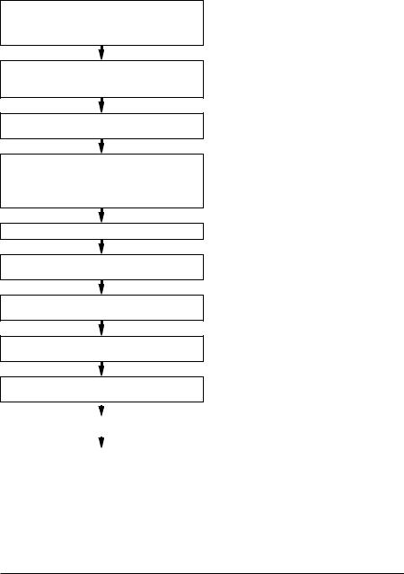
Quick installation and commissioning flowchart
Task
Identify the frame size of your drive: R0…R4.
See
Operation principle and hardware description: Type designation key on page 27
Technical data: Ratings on page 384 or in section Definitions on page 385
Plan the installation: select the cables, etc.
Check the ambient conditions, ratings and required cooling air flow.
Unpack and check the drive.
If the drive will be connected to an IT (ungrounded) or corner grounded system, check that the internal EMC filter is not connected.
Install the drive on a wall or in a cabinet.
Route the cables.
Check the insulation of the input cable and the motor and the motor cable.
Connect the power cables.
Connect the control cables.
Planning the electrical installation on page 35 Technical data on page 383
Mechanical installation: Checking the delivery on page 31
Operation principle and hardware description: Type designation key on page 27
Electrical installation: Checking the compatibility with IT (ungrounded) and corner grounded TN systems on page 47
Mechanical installation on page 29
Planning the electrical installation: Routing the cables on page 41
Electrical installation: Checking the insulation of the assembly on page 45
Electrical installation: Connecting the power cables on page 48
Electrical installation: Connecting the control cables on page 50
|
|
Installation checklist on page 57 |
|
|
|
Check the installation. |
||
|
|
Start-up on page 59 |
|
|
|
|
|
|
Commission the drive. |
||
|
|
|

Operation principle and hardware description 23
3
Operation principle and hardware description
Contents of this chapter
The chapter briefly describes the operation principle, layout, type designation label and type designation information. It also shows a general diagram of power connections and control interfaces.
Operation principle
The ACS320 is a wall or cabinet mountable drive for controlling AC motors.
The figure below shows the simplified main circuit diagram of the drive. The rectifier converts three-phase AC voltage to DC voltage. The capacitor bank of the intermediate circuit stabilizes the DC voltage. The inverter converts the DC voltage back to AC voltage for the AC motor.
Rectifier |
Intermediate |
Inverter |
|
circuit |
|
AC supply |
|
|
|
|
|
|
|
|
|
|
|
|
|
|
|
|
|
|
|
|
|
M |
AC motor |
|
|
|
|
|
|
|
|
|
|
|
|
|
|
|
|
|
|
|
|
|
|||
|
|
|
|
|
|
|
|
|
|
|
|
|
|
|
|
|
|
|
|
|
|||
|
|
|
|
|
|
|
|
|
|
|
|
|
|
|
|
|
|
|
3~ |
||||
|
|
|
|
|
|
|
|
|
|
|
|
|
|
|
|
|
|
|
|
|
|||
|
|
|
|
|
|
|
|
|
|
|
|
|
|
|
|
|
|
|
|
|
|
|
|
|
|
|
|
|
|
|
|
|
|
|
|
|
|
|
|
|
|
|
|
|
|
|
|
|
|
|
|
|
|
|
|
|
|
|
|
|
|
|
|
|
|
|
|
|
|
|
|

24 Operation principle and hardware description
Product overview
Layout
The layout of the drive is presented below. The figure shows a frame size R2 drive. The construction of the different frame sizes R0…R4 varies to some extent.
1 |
Covers on (R2) |
3b |
Covers off (R2) |
||
|
|
|
|
|
|
2 |
3a |
|
|
|
5 |
|
|
|
|
|
|
|
|
|
|
|
6 |
|
8 |
|
8 |
|
7 |
|
|
|
|
||
|
|
9 |
|
|
|
|
|
|
|
|
|
|
|
3c |
12 |
|
11 |
|
4 |
10 |
|
||
|
|
|
14 |
|
13 |
|
|
|
|
|
|
|
|
|
|
18 |
15 |
|
|
|
|
16 |
|
|
|
|
|
|
|
|
2 |
|
|
|
17 |
|
|
|
|
|
|
|
|
|
18 |
|
|
1 |
Cooling outlet through top cover |
2 |
Mounting holes |
3 |
Panel cover (a) / Basic control panel (b) / |
|
Assistant control panel (c) |
4 |
Terminal cover |
5 |
Panel connection |
6 |
Option connection |
7 |
FlashDrop connection |
8 |
Power OK and Fault LEDs. See section |
|
LEDs on page 381. |
9 |
EMC filter grounding screw (EMC). |
|
Note: The screw is on the front in frame |
|
size R4. |
10 |
Varistor grounding screw (VAR). See |
|
section Protecting the contacts of relay |
|
outputs on page 44. |
11 |
EIA-485 connection |
12 |
Jumper J701 for connecting EIA-485 |
|
termination resistor |
13 |
I/O connections |
14 |
Jumper S1 for selecting voltage or current |
|
for analog inputs |
15 |
Input power connection (U1, V1, W1) and |
|
motor connection (U2, V2, W2). (Braking |
|
chopper connection is disabled.) |
16 |
I/O clamping plate |
17 |
Clamping plate |
18 |
Clamps |
Operation principle and hardware description 25
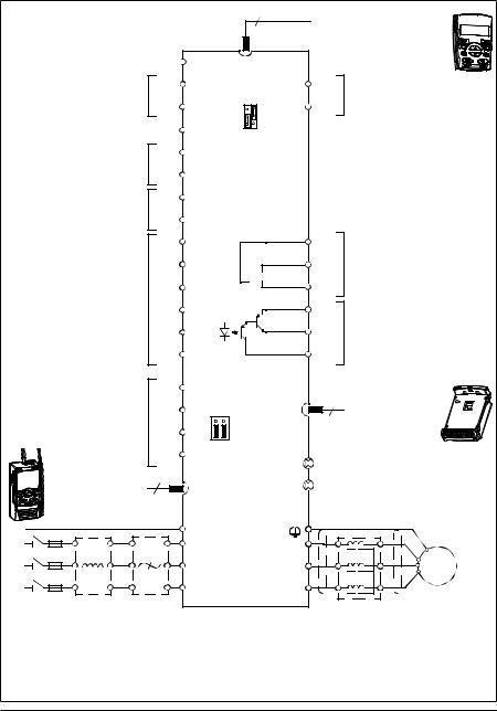
Power connections and control interfaces
The diagram gives an overview of connections. I/O connections are parameterable.
8
Control panel (RJ-45)
|
Screen |
|
|
1 |
SCR |
|
|
|
|
|
|
Analog input 1 |
|
2 |
AI1 |
S1 |
AO |
7 |
Analog output |
||
|
|
|
|
<![if ! IE]> <![endif]>AI1 AI2 |
|
|
||||
|
0…10 V |
|
3 |
GND |
GND |
8 |
0…20 mA |
|
||
|
|
mA |
|
|||||||
|
|
|
|
|
|
|||||
Reference voltage |
|
4 |
+10V |
V |
|
|
|
|
||
+10 V DC, max. 10 mA |
|
|
|
|
|
|
||||
|
|
|
|
|
|
|
|
|||
|
Analog input 2 |
|
5 |
AI2 |
|
|
|
|
|
|
|
|
|
|
|
|
|
|
|
||
|
|
|
|
6 |
GND |
|
|
|
|
|
Aux. voltage output |
|
9 |
+24 V |
|
|
|
PROGRAMMABLE RELAY |
|||
|
|
|
|
|
|
AND DIGITAL OUTPUTS |
||||
+24 V DC, max. 200 mA |
|
10 |
GND |
|
|
|
||||
|
|
|
|
|
|
|||||
|
|
|
|
|
ROCOM 17 |
|
|
|||
|
|
|
|
11 |
DCOM |
|
|
|
||
|
|
|
|
12 |
DI1 |
|
RONC |
18 |
Relay output |
|
|
|
|
|
|
|
|
RONO |
|
250 V AC / 30 V DC / 6 A |
|
PROGRAMMABLE |
|
13 |
DI2 |
|
19 |
|
|
|||
|
DIGITAL INPUTS |
|
14 |
DI3 |
|
DOSRC |
20 |
Digital/frequency output, |
||
|
|
|
|
15 |
DI4 |
|
DOOUT |
21 |
||
|
|
|
|
|
PNP transistor type |
|||||
DI5 can also be used |
|
16 |
DI5 |
|
DOGND |
22 |
30 V DC, max. 100 mA |
|||
|
|
|
|
|||||||
as a frequency input |
|
|
|
|
|
|
|
|
||
|
EFB Comm port |
|
23 |
SHIELD |
|
6 |
|
|
||
Modbus RTU (EIA-485) |
|
24 |
B J701 |
|
Output relay |
|
||||
Johnson Controls N2 |
|
|
|
|||||||
|
|
|
module MREL-01 |
|||||||
Siemens Building Technology |
|
|
|
|
|
|
||||
|
25 |
A |
|
|
|
|
|
|||
FLN (P1), BACnet (MS/TP) |
|
|
|
|
|
|
||||
|
|
|
|
26 |
GND_A |
EMC |
|
EMC filter grounding screw |
||
|
|
|
6 |
|
|
|
||||
|
FlashDrop |
|
|
VAR |
|
Varistor grounding screw |
||||
|
|
|
|
|
|
|||||
PE |
|
|
|
|
PE |
|
|
|
|
|
L1 |
|
|
|
|
U1 |
|
U2 |
|
|
M |
L2 |
|
|
|
|
V1 |
|
V2 |
|
|
|
|
|
|
|
|
|
|
3 ~ |
|||
L3 |
|
|
|
|
|
|
|
|
|
|
|
|
|
|
W1 |
|
W2 |
|
|
|
|
3-phase |
Input |
EMC |
|
|
|
|
|
Output |
AC motor |
|
power |
choke*) |
filter*) |
|
|
|
|
choke*) |
|
||
supply, |
|
|
|
|
|
|
|
|
|
|
200…480 |
|
|
|
|
|
|
|
|
|
|
V AC |
|
|
|
|
|
|
|
|
|
|
*) Optional, not provided with the drive.
Note: For 1-phase power supply, connect power to U1/L and V1/N terminals.
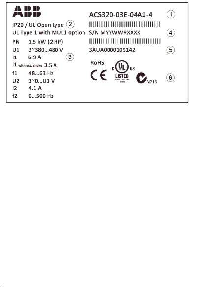
26 Operation principle and hardware description
See Application macros on page 79 for I/O connections for the different macros and chapter Electrical installation on page 45 for installation in general.
Type designation label
The type designation label is attached to the left side of the drive. An example label and explanation of the label contents are shown below.
1 |
Type designation, see section Type designation key on page 27 |
|
|
|
|
2 |
Degree of protection by enclosure (IP and UL/NEMA) |
|
|
|
|
3 |
Nominal ratings, see section Ratings on page 384 or Definitions on page 385. |
|
|
|
|
4 |
Serial number of format MYYWWRXXXX, where |
|
|
M: |
Manufacturer |
|
YY: |
09, 10, 11, … for 2009, 2010, 2011, … |
|
WW: |
01, 02, 03, … for week 1, week 2, week 3, … |
|
R: |
A, B, C, … for product revision number |
|
XXXX: |
Integer starting every week from 0001 |
|
|
|
5 |
ABB MRP code of the drive |
|
|
|
|
6 |
CE marking and C-Tick, C-UL US and RoHS marks (the label of your drive shows the |
|
|
valid markings) |
|
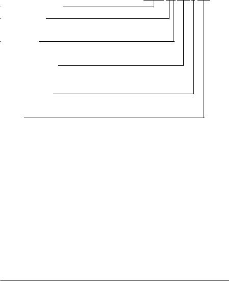
Operation principle and hardware description 27
Type designation key
The type designation contains information on the specifications and configuration of the drive. You find the type designation on the type designation label attached to the drive. The first digits from the left express the basic configuration, for example ACS320-03U-09A7-4. The optional selections are given after that, separated by + signs, for example +J404. The explanations of the type designation selections are described below.
ACS320-03X-08A8-4+J404+...
ACS320 product series
1-phase/3-phase
01 = 1-phase input
03 = 3-phase input
Configuration
E = EMC filter connected, 50 Hz frequency
U = EMC filter disconnected, 60 Hz frequency
Output current rating
In format xxAy, where xx indicates the integer part and y the fractional part, eg, 08A8 means 8.8 A. For more information on ratings, types and voltages, see sections starting on page 383.
Input voltage range
2 = 200 … 240 V AC
4 = 380 … 480 V AC
Options
J404 = ACS-CP-C basic control panel
J400 = ACH-CP-B advanced HVAC control panel 1)
R700 = ACS320 user’s manual in English (3AUA0000062599 [EN])
E202 = RFI filter (available for European market only)
1) |
The ACS320 is compatible with panels that have the following panel revisions and panel firmware |
|||
|
versions. |
|
|
|
|
|
|
|
|
Panel type |
Type code |
Panel revision |
Panel firmware version |
|
Basic control panel 2) |
ACS-CP-C |
M or later |
1.13 or later |
|
Advanced HVAC control panel |
ACH-CP-B |
X or later |
2.04 or later |
|
2) |
Available for North American market only. |
|
|
|

28 Operation principle and hardware description

Mechanical installation 29
4
Mechanical installation
Contents of this chapter
The chapter tells how to check the installation site, unpack, check the delivery and install the drive mechanically.
Checking the installation site
The drive may be installed on the wall or in a cabinet. Check the enclosure requirements for the need to use the NEMA 1 option in wall installations (see chapter
Technical data on page 383.
The drive can be installed in three different ways, depending on the frame size:
a)back mounting (all frame sizes)
b)side mounting (frame sizes R0…R2)
c)DIN rail mounting (all frame sizes).
The drive must be installed in an upright position.
Check the installation site according to the requirements below. Refer to chapter Dimension drawings on page 403 for frame details.
Requirements for the installation site
Operation conditions
See chapter Technical data on page 383 for the allowed operation conditions of the drive.
Wall
The wall should be as close to vertical and even as possible, of non-flammable material and strong enough to carry the weight of the drive.

30 Mechanical installation
Floor
The floor/material below the installation should be non-flammable.
Free space around the drive
The required free space for cooling above and below the drive is 75 mm (3 in). No free space is required on the sides of the drive, so drives can be installed side by side.
Required tools
To install the drive, you need the following tools:
•screwdrivers (as appropriate for the mounting hardware used)
•wire stripper
•tape measure
•drill (if the drive will be installed with screws/bolts)
•mounting hardware: screws or bolts (if the drive will be installed with screws/bolts). For the number of screws/bolts, see With screws on page 32.
Loading...