


ACS880-07
Table of contents
 Loading...
ABB industrial drives
Hardware manual
ACS880-07 drives
(45 to 710 kW, 50 to 700 hp)

List of related manuals
ACS880-07 manuals
Drive hardware manuals and guides Code (English)
ACS880-07 hardware manual 3AUA0000105718
ACS-AP-X assistant control panels user’s manual 3AUA0000085685
ACS880-07 lifting device user’s manual 3AUA0000131337
Drive firmware manuals and guides
ACS880 primary control program firmware manual 3AUA0000085967
Quick start-up guide for ACS880 drives with primary
control program
Option manuals and guides
Drive composer start-up and maintenance PC tool user’s
manual
FSO-12 safety functions module user’s manual 3AXD50000015612
User’s manual for Prevention of unexpected start-up
(+Q950) for ACS880-07/17/37 drives
User’s manual for Emergency stop, stop category 0
(+Q951) for ACS880-07/17/37 drives
User’s manual for Emergency stop, stop category 1
(+Q952) for ACS880-07/17/37 drives
User’s manual for Prevention of unexpected start-up
(+Q957) for ACS880-07/17/37 drives
User’s manual for Emergency stop, stop category 0
(+Q963) for ACS880-07/17/37 drives
User’s manual for Emergency stop, stop category 1
(+Q964) for ACS880-07/17/37 drives
User’s manual for Emergency stop, configurable stop
category 0 or 1 (+Q978) for ACS880-07/17/37 drives
User’s manual for Emergency stop, configurable stop
category 0 or 1 (+Q979) for ACS880-07/17/37 drives
3AUA0000098062
3AUA0000094606
3AUA0000145922
3AUA0000119895
3AUA0000119896
3AUA0000119910
3AUA0000119908
3AUA0000119909
3AUA0000145920
3AUA0000145921
You can find manuals and other product documents in PDF format on the Internet. See section
Document library on the Internet on the inside of the back cover. For manuals not available in the
Document library, contact your local ABB representative.
The code below opens an online listing of the manuals applicable to this product.

Hardware manual
ACS880-07 drives
(45 to 710 kW, 50 to 700 hp)
Table of contents
1. Safety instructions
4. Mechanical installation
6. Electrical installation
10. Start-up
2015 ABB Oy. All Rights Reserved.
3AUA0000105718 Rev E
EN
EFFECTIVE: 2015-06-25


5
Table of contents
1. Safety instructions
Contents of this chapter . . . . . . . . . . . . . . . . . . . . . . . . . . . . . . . . . . . . . . . . . . . . . . . . . 13
Use of warnings . . . . . . . . . . . . . . . . . . . . . . . . . . . . . . . . . . . . . . . . . . . . . . . . . . . . . . . 13
General safety in installation, start-up and maintenance . . . . . . . . . . . . . . . . . . . . . . . . 14
Electrical safety in installation, start-up and maintenance . . . . . . . . . . . . . . . . . . . . . . . 16
Precautions before electrical work . . . . . . . . . . . . . . . . . . . . . . . . . . . . . . . . . . . . . . . 16
Additional instructions and notes . . . . . . . . . . . . . . . . . . . . . . . . . . . . . . . . . . . . . . . . 17
Grounding . . . . . . . . . . . . . . . . . . . . . . . . . . . . . . . . . . . . . . . . . . . . . . . . . . . . . . . . . . 18
Additional instructions for permanent magnet motor drives . . . . . . . . . . . . . . . . . . . . . . 19
Safety in installation, start-up and maintenance . . . . . . . . . . . . . . . . . . . . . . . . . . . . . 19
2. Introduction to the manual
Contents of this chapter . . . . . . . . . . . . . . . . . . . . . . . . . . . . . . . . . . . . . . . . . . . . . . . . . 21
Target audience . . . . . . . . . . . . . . . . . . . . . . . . . . . . . . . . . . . . . . . . . . . . . . . . . . . . . . . 21
Contents of the manual . . . . . . . . . . . . . . . . . . . . . . . . . . . . . . . . . . . . . . . . . . . . . . . . . . 21
Related manuals . . . . . . . . . . . . . . . . . . . . . . . . . . . . . . . . . . . . . . . . . . . . . . . . . . . . . . . 22
Categorization by frame size and option code . . . . . . . . . . . . . . . . . . . . . . . . . . . . . . . . 22
Quick installation, start-up and operating flowchart . . . . . . . . . . . . . . . . . . . . . . . . . . . . 22
Terms and abbreviations . . . . . . . . . . . . . . . . . . . . . . . . . . . . . . . . . . . . . . . . . . . . . . . . . 23
3. Operation principle and hardware description
Contents of this chapter . . . . . . . . . . . . . . . . . . . . . . . . . . . . . . . . . . . . . . . . . . . . . . . . . 25
Product overview . . . . . . . . . . . . . . . . . . . . . . . . . . . . . . . . . . . . . . . . . . . . . . . . . . . . . . . 25
Single-line circuit diagram of the drive . . . . . . . . . . . . . . . . . . . . . . . . . . . . . . . . . . . . 26
Block diagram of the brake and DC options (+D150, +D151 and +H356) . . . . . . . . . 27
General information on the cabinet layout . . . . . . . . . . . . . . . . . . . . . . . . . . . . . . . . . 28
Cabinet layout of frames R6 to R8 . . . . . . . . . . . . . . . . . . . . . . . . . . . . . . . . . . . . . . . 29
Cabinet layout of frames R6 to R8 with option +C129 . . . . . . . . . . . . . . . . . . . . . . . . 30
Cabinet layout of frames R6 to R8 with options +C129 and +F289 . . . . . . . . . . . . . . 31
Cabinet layout of frame R9 . . . . . . . . . . . . . . . . . . . . . . . . . . . . . . . . . . . . . . . . . . . . . 33
Cabinet layout of frame R9 with options +C129 and +F289 . . . . . . . . . . . . . . . . . . . . 35
Cabinet layout of frames R10 and R11 – bottom entry and exit of cables . . . . . . . . . 37
Cabinet layout of frames R10 and R11 – top entry and exit of cables
(option +C129) . . . . . . . . . . . . . . . . . . . . . . . . . . . . . . . . . . . . . . . . . . . . . . . . . . . . . . 39
Overview of power and control connections . . . . . . . . . . . . . . . . . . . . . . . . . . . . . . . . 40
Door switches and lights . . . . . . . . . . . . . . . . . . . . . . . . . . . . . . . . . . . . . . . . . . . . . . . 42
Main switch-disconnector Q1 . . . . . . . . . . . . . . . . . . . . . . . . . . . . . . . . . . . . . . . . . 42
Control panel . . . . . . . . . . . . . . . . . . . . . . . . . . . . . . . . . . . . . . . . . . . . . . . . . . . . . . . 43
Control by PC tools . . . . . . . . . . . . . . . . . . . . . . . . . . . . . . . . . . . . . . . . . . . . . . . . 43
Descriptions of cabinet options . . . . . . . . . . . . . . . . . . . . . . . . . . . . . . . . . . . . . . . . . . . . 43
Degree of protection . . . . . . . . . . . . . . . . . . . . . . . . . . . . . . . . . . . . . . . . . . . . . . . . . . 43
Definitions . . . . . . . . . . . . . . . . . . . . . . . . . . . . . . . . . . . . . . . . . . . . . . . . . . . . . . . 43
IP22 and UL Type 1 (standard) . . . . . . . . . . . . . . . . . . . . . . . . . . . . . . . . . . . . . . . 43
IP42 and UL Type 1 Filtered (option +B054) . . . . . . . . . . . . . . . . . . . . . . . . . . . . . 44
IP54 and UL Type 12 (option +B055) . . . . . . . . . . . . . . . . . . . . . . . . . . . . . . . . . . 44
Channeled air inlet through bottom (option +C128) . . . . . . . . . . . . . . . . . . . . . . . . . . 44

6
Channeled air outlet (option +C130) . . . . . . . . . . . . . . . . . . . . . . . . . . . . . . . . . . . . . 44
Marine construction (option +C121) . . . . . . . . . . . . . . . . . . . . . . . . . . . . . . . . . . . . . 44
UL listed (option +C129) . . . . . . . . . . . . . . . . . . . . . . . . . . . . . . . . . . . . . . . . . . . . . . 45
CSA approved (option +C134) . . . . . . . . . . . . . . . . . . . . . . . . . . . . . . . . . . . . . . . . . 45
Plinth height (options +C164 and +C179) . . . . . . . . . . . . . . . . . . . . . . . . . . . . . . . . . 45
Seismic design (option +C180) . . . . . . . . . . . . . . . . . . . . . . . . . . . . . . . . . . . . . . . . . 45
Resistor braking (options +D150 and +D151) . . . . . . . . . . . . . . . . . . . . . . . . . . . . . . 45
EMC filters (options + E200, +E201, +E202, +E210) . . . . . . . . . . . . . . . . . . . . . . . . 45
du/dt filter (option +E205) . . . . . . . . . . . . . . . . . . . . . . . . . . . . . . . . . . . . . . . . . . . . . 45
Sine filter (option +E206) . . . . . . . . . . . . . . . . . . . . . . . . . . . . . . . . . . . . . . . . . . . . . 46
Common mode filter (option +E208) . . . . . . . . . . . . . . . . . . . . . . . . . . . . . . . . . . . . . 46
Cabinet heater with external supply (option +G300) . . . . . . . . . . . . . . . . . . . . . . . . . 46
Terminals for external uninterruptible control voltage (option +G307) . . . . . . . . . . . 46
Output for motor space heater (option +G313) . . . . . . . . . . . . . . . . . . . . . . . . . . . . . 47
Additional wire markings (options +G340 and +G342) . . . . . . . . . . . . . . . . . . . . . . . 47
US/UK gland/conduit plate (option +H358) . . . . . . . . . . . . . . . . . . . . . . . . . . . . . . . . 47
Additional terminal block X504 (option +L504) . . . . . . . . . . . . . . . . . . . . . . . . . . . . . 47
Thermistor relays (options +L505, +2L505) . . . . . . . . . . . . . . . . . . . . . . . . . . . . . . . 48
Pt100 relays (options +3L506, +5L506, +8L506) . . . . . . . . . . . . . . . . . . . . . . . . . . . 48
What the option contains . . . . . . . . . . . . . . . . . . . . . . . . . . . . . . . . . . . . . . . . . . . 48
Description . . . . . . . . . . . . . . . . . . . . . . . . . . . . . . . . . . . . . . . . . . . . . . . . . . . . . . 48
Type designation label . . . . . . . . . . . . . . . . . . . . . . . . . . . . . . . . . . . . . . . . . . . . . . . . . . 49
Type designation key . . . . . . . . . . . . . . . . . . . . . . . . . . . . . . . . . . . . . . . . . . . . . . . . . . . 49
4. Mechanical installation
Contents of this chapter . . . . . . . . . . . . . . . . . . . . . . . . . . . . . . . . . . . . . . . . . . . . . . . . . 55
Examining the installation site . . . . . . . . . . . . . . . . . . . . . . . . . . . . . . . . . . . . . . . . . . . . 55
Necessary tools . . . . . . . . . . . . . . . . . . . . . . . . . . . . . . . . . . . . . . . . . . . . . . . . . . . . . . . 56
Moving and unpacking the drive . . . . . . . . . . . . . . . . . . . . . . . . . . . . . . . . . . . . . . . . . . 57
Unpacking the transport package . . . . . . . . . . . . . . . . . . . . . . . . . . . . . . . . . . . . . . . 58
Checking the delivery . . . . . . . . . . . . . . . . . . . . . . . . . . . . . . . . . . . . . . . . . . . . . . . . . . 58
Moving the drive cabinet . . . . . . . . . . . . . . . . . . . . . . . . . . . . . . . . . . . . . . . . . . . . . . . . 58
Installing the IP54 roof . . . . . . . . . . . . . . . . . . . . . . . . . . . . . . . . . . . . . . . . . . . . . . . . . . 59
Frames R6 to R8 . . . . . . . . . . . . . . . . . . . . . . . . . . . . . . . . . . . . . . . . . . . . . . . . . . . . 59
Frame R9 . . . . . . . . . . . . . . . . . . . . . . . . . . . . . . . . . . . . . . . . . . . . . . . . . . . . . . . . . 60
Frames R10 and R11 . . . . . . . . . . . . . . . . . . . . . . . . . . . . . . . . . . . . . . . . . . . . . . . . 61
Lifting the drive cabinet . . . . . . . . . . . . . . . . . . . . . . . . . . . . . . . . . . . . . . . . . . . . . . . 62
Moving the cabinet on rollers . . . . . . . . . . . . . . . . . . . . . . . . . . . . . . . . . . . . . . . . . . 63
Final placement of the cabinet . . . . . . . . . . . . . . . . . . . . . . . . . . . . . . . . . . . . . . . . . 63
Fastening the cabinet to the floor and wall or roof (non-marine units) . . . . . . . . . . . . . . 64
General rules . . . . . . . . . . . . . . . . . . . . . . . . . . . . . . . . . . . . . . . . . . . . . . . . . . . . . . . 64
Fastening methods . . . . . . . . . . . . . . . . . . . . . . . . . . . . . . . . . . . . . . . . . . . . . . . . . . 65
Alternative 1 – Clamping . . . . . . . . . . . . . . . . . . . . . . . . . . . . . . . . . . . . . . . . . . . . . . 65
Alternative 2 – Using the holes inside the cabinet . . . . . . . . . . . . . . . . . . . . . . . . . . 65
Fastening the cabinet to the floor and roof/wall (marine units) . . . . . . . . . . . . . . . . . . . 66
Miscellaneous . . . . . . . . . . . . . . . . . . . . . . . . . . . . . . . . . . . . . . . . . . . . . . . . . . . . . . . . 67
Cable duct in the floor below the cabinet . . . . . . . . . . . . . . . . . . . . . . . . . . . . . . . . . 67
Air inlet through the bottom (option +C128+B055) . . . . . . . . . . . . . . . . . . . . . . . . . . 67
Air outlet duct on the cabinet roof (option +C130) . . . . . . . . . . . . . . . . . . . . . . . . . . 68
Calculating the required static pressure difference . . . . . . . . . . . . . . . . . . . . . . . 68
Arc welding . . . . . . . . . . . . . . . . . . . . . . . . . . . . . . . . . . . . . . . . . . . . . . . . . . . . . . . . 69

7
5. Guidelines for planning the electrical installation
Contents of this chapter . . . . . . . . . . . . . . . . . . . . . . . . . . . . . . . . . . . . . . . . . . . . . . . . . 71
Limitation of liability . . . . . . . . . . . . . . . . . . . . . . . . . . . . . . . . . . . . . . . . . . . . . . . . . . . . . 71
Selecting the supply disconnecting device . . . . . . . . . . . . . . . . . . . . . . . . . . . . . . . . . . . 71
Selecting the main contactor . . . . . . . . . . . . . . . . . . . . . . . . . . . . . . . . . . . . . . . . . . . . . . 71
Examining the compatibility of the motor and drive . . . . . . . . . . . . . . . . . . . . . . . . . . . . . 72
Protecting the motor insulation and bearings . . . . . . . . . . . . . . . . . . . . . . . . . . . . . . . 72
Requirements table . . . . . . . . . . . . . . . . . . . . . . . . . . . . . . . . . . . . . . . . . . . . . . . . . . 73
Additional requirements for explosion-safe (EX) motors . . . . . . . . . . . . . . . . . . . . 74
Additional requirements for ABB motors of types other than M2_, M3_, M4_, HX_
and AM_ . . . . . . . . . . . . . . . . . . . . . . . . . . . . . . . . . . . . . . . . . . . . . . . . . . . . . . . . . 75
Additional requirements for the braking applications . . . . . . . . . . . . . . . . . . . . . . . 75
Additional requirements for ABB high-output and IP23 motors . . . . . . . . . . . . . . . 75
Additional requirements for non-ABB high-output and IP23 motors . . . . . . . . . . . 76
Additional data for calculating the rise time and the peak line-to-line voltage . . . . 77
Additional note for sine filters . . . . . . . . . . . . . . . . . . . . . . . . . . . . . . . . . . . . . . . . . 77
Selecting the power cables . . . . . . . . . . . . . . . . . . . . . . . . . . . . . . . . . . . . . . . . . . . . . . . 78
General rules . . . . . . . . . . . . . . . . . . . . . . . . . . . . . . . . . . . . . . . . . . . . . . . . . . . . . . . 78
Typical power cable sizes . . . . . . . . . . . . . . . . . . . . . . . . . . . . . . . . . . . . . . . . . . . . . . 79
Alternative power cable types . . . . . . . . . . . . . . . . . . . . . . . . . . . . . . . . . . . . . . . . . . . 80
Recommended power cable types . . . . . . . . . . . . . . . . . . . . . . . . . . . . . . . . . . . . . 80
Power cable types for limited use . . . . . . . . . . . . . . . . . . . . . . . . . . . . . . . . . . . . . 80
Not allowed power cable types . . . . . . . . . . . . . . . . . . . . . . . . . . . . . . . . . . . . . . . 81
Motor cable shield . . . . . . . . . . . . . . . . . . . . . . . . . . . . . . . . . . . . . . . . . . . . . . . . . . . 81
Additional US requirements . . . . . . . . . . . . . . . . . . . . . . . . . . . . . . . . . . . . . . . . . . . . 81
Conduit . . . . . . . . . . . . . . . . . . . . . . . . . . . . . . . . . . . . . . . . . . . . . . . . . . . . . . . . . . 81
Armored cable / shielded power cable . . . . . . . . . . . . . . . . . . . . . . . . . . . . . . . . . . 81
Planning the braking system . . . . . . . . . . . . . . . . . . . . . . . . . . . . . . . . . . . . . . . . . . . . . . 82
Selecting the control cables . . . . . . . . . . . . . . . . . . . . . . . . . . . . . . . . . . . . . . . . . . . . . . 82
Shielding . . . . . . . . . . . . . . . . . . . . . . . . . . . . . . . . . . . . . . . . . . . . . . . . . . . . . . . . . . . 82
Signals in separate cables . . . . . . . . . . . . . . . . . . . . . . . . . . . . . . . . . . . . . . . . . . . . . 82
Signals allowed to be run in the same cable . . . . . . . . . . . . . . . . . . . . . . . . . . . . . . . 82
Relay cable type . . . . . . . . . . . . . . . . . . . . . . . . . . . . . . . . . . . . . . . . . . . . . . . . . . . . . 82
Control panel cable length and type . . . . . . . . . . . . . . . . . . . . . . . . . . . . . . . . . . . . . . 82
Routing the cables . . . . . . . . . . . . . . . . . . . . . . . . . . . . . . . . . . . . . . . . . . . . . . . . . . . . . 83
Separate control cable ducts . . . . . . . . . . . . . . . . . . . . . . . . . . . . . . . . . . . . . . . . . . . 83
Continuous motor cable shield or enclosure for equipment on the motor cable . . . . . 83
Implementing thermal overload and short-circuit protection . . . . . . . . . . . . . . . . . . . . . . 84
Protecting the drive and input power cable in short-circuits . . . . . . . . . . . . . . . . . . . . 84
Protecting the motor and motor cable in short-circuits . . . . . . . . . . . . . . . . . . . . . . . . 84
Protecting the drive and the input power and motor cables against thermal
overload . . . . . . . . . . . . . . . . . . . . . . . . . . . . . . . . . . . . . . . . . . . . . . . . . . . . . . . . . . . 85
Protecting the motor against thermal overload . . . . . . . . . . . . . . . . . . . . . . . . . . . . . . 85
Protecting the drive against ground faults . . . . . . . . . . . . . . . . . . . . . . . . . . . . . . . . . . . . 85
Residual current device compatibility . . . . . . . . . . . . . . . . . . . . . . . . . . . . . . . . . . . . . 85
Implementing the emergency stop function . . . . . . . . . . . . . . . . . . . . . . . . . . . . . . . . . . 85
Implementing the Safe torque off function . . . . . . . . . . . . . . . . . . . . . . . . . . . . . . . . . . . 86
Implementing Prevention of unexpected start-up function . . . . . . . . . . . . . . . . . . . . . . . 86
Implementing the functions provided by the FSO-xx safety functions module (option
+Q972 or +Q973) . . . . . . . . . . . . . . . . . . . . . . . . . . . . . . . . . . . . . . . . . . . . . . . . . . . . . . 86
Declaration of Conformity . . . . . . . . . . . . . . . . . . . . . . . . . . . . . . . . . . . . . . . . . . . . . . 86
Implementing the Power-loss ride-through function . . . . . . . . . . . . . . . . . . . . . . . . . . . . 87
Units with main contactor (option +F250) . . . . . . . . . . . . . . . . . . . . . . . . . . . . . . . . . . 87

8
Supplying power for the auxiliary circuits . . . . . . . . . . . . . . . . . . . . . . . . . . . . . . . . . . . . 87
Using power factor compensation capacitors with the drive . . . . . . . . . . . . . . . . . . . . . 87
Implementing a safety switch between the drive and the motor . . . . . . . . . . . . . . . . . . 88
Using a contactor between the drive and the motor . . . . . . . . . . . . . . . . . . . . . . . . . . . 88
Implementing a bypass connection . . . . . . . . . . . . . . . . . . . . . . . . . . . . . . . . . . . . . . . . 89
Example bypass connection . . . . . . . . . . . . . . . . . . . . . . . . . . . . . . . . . . . . . . . . . . . 89
Switching the motor power supply from drive to direct-on-line . . . . . . . . . . . . . . . 90
Switching the motor power supply from direct-on-line to drive . . . . . . . . . . . . . . . 90
Protecting the contacts of relay outputs . . . . . . . . . . . . . . . . . . . . . . . . . . . . . . . . . . . . . 90
Connecting a motor temperature sensor to the drive I/O . . . . . . . . . . . . . . . . . . . . . . . . 91
6. Electrical installation
Contents of this chapter . . . . . . . . . . . . . . . . . . . . . . . . . . . . . . . . . . . . . . . . . . . . . . . . . 93
Warnings . . . . . . . . . . . . . . . . . . . . . . . . . . . . . . . . . . . . . . . . . . . . . . . . . . . . . . . . . . . . 93
Checking the insulation of the assembly . . . . . . . . . . . . . . . . . . . . . . . . . . . . . . . . . . . . 93
Drive . . . . . . . . . . . . . . . . . . . . . . . . . . . . . . . . . . . . . . . . . . . . . . . . . . . . . . . . . . . . . 93
Input cable . . . . . . . . . . . . . . . . . . . . . . . . . . . . . . . . . . . . . . . . . . . . . . . . . . . . . . . . . 93
Motor and motor cable . . . . . . . . . . . . . . . . . . . . . . . . . . . . . . . . . . . . . . . . . . . . . . . 94
Brake resistor assembly . . . . . . . . . . . . . . . . . . . . . . . . . . . . . . . . . . . . . . . . . . . . . . 94
Checking the compatibility with IT (ungrounded) systems . . . . . . . . . . . . . . . . . . . . . . . 94
Attaching the device stickers on the cabinet door . . . . . . . . . . . . . . . . . . . . . . . . . . . . . 95
Connecting the power cables . . . . . . . . . . . . . . . . . . . . . . . . . . . . . . . . . . . . . . . . . . . . 96
Connection diagram . . . . . . . . . . . . . . . . . . . . . . . . . . . . . . . . . . . . . . . . . . . . . . . . . 96
Layout of the power cable connection terminals and lead-throughs (frames R6
to R8) . . . . . . . . . . . . . . . . . . . . . . . . . . . . . . . . . . . . . . . . . . . . . . . . . . . . . . . . . . . . 97
Layout of the power cable connection terminals and lead-throughs (frames R6
to R8 with option +C129) . . . . . . . . . . . . . . . . . . . . . . . . . . . . . . . . . . . . . . . . . . . . . 98
Layout of the power cable connection terminals and lead-throughs (frames R6
to R8 with options +C129+F277+F289) . . . . . . . . . . . . . . . . . . . . . . . . . . . . . . . . . . 99
Layout of the input and motor cable connection terminals (frame R9) . . . . . . . . . . 100
Layout of the power cable connection terminals and lead-throughs (frame R9 with
option +C129) . . . . . . . . . . . . . . . . . . . . . . . . . . . . . . . . . . . . . . . . . . . . . . . . . . . . . 101
Layout of the input and motor cable connection terminals (frames R10 and R11) . 102
Layout of the input and motor cable connection terminals (frames R10 and R11
with option +C129) . . . . . . . . . . . . . . . . . . . . . . . . . . . . . . . . . . . . . . . . . . . . . . . . . 102
Lead-through of external resistor and DC cables . . . . . . . . . . . . . . . . . . . . . . . . . . 103
Connection procedure (IEC) . . . . . . . . . . . . . . . . . . . . . . . . . . . . . . . . . . . . . . . . . . 103
Connection procedure (US) . . . . . . . . . . . . . . . . . . . . . . . . . . . . . . . . . . . . . . . . . . 106
Grounding the motor cable shield at the motor end . . . . . . . . . . . . . . . . . . . . . . . . 107
DC connection (option +H356) . . . . . . . . . . . . . . . . . . . . . . . . . . . . . . . . . . . . . . . . 107
Connecting the control cables . . . . . . . . . . . . . . . . . . . . . . . . . . . . . . . . . . . . . . . . . . . 107
Control cable connection procedure . . . . . . . . . . . . . . . . . . . . . . . . . . . . . . . . . . . . 107
Grounding the outer shields of the control cables at the cabinet lead-through . 108
Routing the control cables inside the cabinet (frames R6 to R8) . . . . . . . . . . . . 110
Routing the control cables inside the cabinet (frame R9) . . . . . . . . . . . . . . . . . . 111
Routing the control cables inside the cabinet (frames R10 and R11) . . . . . . . . 112
Connecting the control unit cables . . . . . . . . . . . . . . . . . . . . . . . . . . . . . . . . . . . 112
Connecting the external 230 V or 115 V uninterruptible control voltage (UPS,
option +G307) . . . . . . . . . . . . . . . . . . . . . . . . . . . . . . . . . . . . . . . . . . . . . . . . . . . 114
Connecting the emergency stop push buttons (options +Q951, +Q952, +Q963,
+Q964) . . . . . . . . . . . . . . . . . . . . . . . . . . . . . . . . . . . . . . . . . . . . . . . . . . . . . . . . 114
Wiring the starter for auxiliary motor fan (options +M600…+M605) . . . . . . . . . . 114
Wiring the thermistor relay(s) (options +L505 and +2L505) . . . . . . . . . . . . . . . . 115

9
Wiring the Pt100 relays (options +2L506, +3L506, +5L506 and +8L506) . . . . . . 116
Connecting the external power supply cables for the cabinet heater and lighting
and motor heater (options +G300, +G301 and +G313) . . . . . . . . . . . . . . . . . . . . 117
Wiring ground fault monitoring for IT ungrounded systems (option +Q954) . . . . 118
Setting the voltage range of the auxiliary control voltage transformer (T21) . . . . . . . . . 118
Connecting a PC . . . . . . . . . . . . . . . . . . . . . . . . . . . . . . . . . . . . . . . . . . . . . . . . . . . . . . 119
Installing option modules . . . . . . . . . . . . . . . . . . . . . . . . . . . . . . . . . . . . . . . . . . . . . . . . 120
Mechanical installation of I/O extension, fieldbus adapter and pulse encoder
interface modules . . . . . . . . . . . . . . . . . . . . . . . . . . . . . . . . . . . . . . . . . . . . . . . . . . . 120
Wiring I/O extension, fieldbus adapter and pulse encoder interface modules . . . . . 120
Installation of safety functions modules (frames R6 to R9) . . . . . . . . . . . . . . . . . . . 121
installation of safety functions modules (frames R10 and R11) . . . . . . . . . . . . . . . . 122
Case 1: FSO-xx safety functions module on Slot 2 . . . . . . . . . . . . . . . . . . . . . . . 122
Case 2: FSO-xx safety functions module above the control unit . . . . . . . . . . . . . 124
7. Control unit of frames R6 to R9
Contents of this chapter . . . . . . . . . . . . . . . . . . . . . . . . . . . . . . . . . . . . . . . . . . . . . . . . 125
Layout . . . . . . . . . . . . . . . . . . . . . . . . . . . . . . . . . . . . . . . . . . . . . . . . . . . . . . . . . . . . . . 126
Default I/O connection diagram of frames R6 to R9 . . . . . . . . . . . . . . . . . . . . . . . . . . . 127
Notes: . . . . . . . . . . . . . . . . . . . . . . . . . . . . . . . . . . . . . . . . . . . . . . . . . . . . . . . . . . 128
Jumpers and switches . . . . . . . . . . . . . . . . . . . . . . . . . . . . . . . . . . . . . . . . . . . . . . . 128
External power supply for the control unit . . . . . . . . . . . . . . . . . . . . . . . . . . . . . . . . 128
AI1 and AI2 as Pt100, Pt1000, PTC and KTY84 sensor inputs (XAI, XAO) . . . . . . . 129
DI6 (XDI:6) as PTC sensor input . . . . . . . . . . . . . . . . . . . . . . . . . . . . . . . . . . . . . . . 130
DIIL input (XD24:1) . . . . . . . . . . . . . . . . . . . . . . . . . . . . . . . . . . . . . . . . . . . . . . . . . . 130
Drive-to-drive link (XD2D) . . . . . . . . . . . . . . . . . . . . . . . . . . . . . . . . . . . . . . . . . . . . . 130
Safe torque off (XSTO) . . . . . . . . . . . . . . . . . . . . . . . . . . . . . . . . . . . . . . . . . . . . . . . 131
Safety functions module connection (X12) . . . . . . . . . . . . . . . . . . . . . . . . . . . . . . . . 131
Technical data . . . . . . . . . . . . . . . . . . . . . . . . . . . . . . . . . . . . . . . . . . . . . . . . . . . . . . . . 131
8. Control unit of frames R10 and R11
Contents of this chapter . . . . . . . . . . . . . . . . . . . . . . . . . . . . . . . . . . . . . . . . . . . . . . . . 135
Layout . . . . . . . . . . . . . . . . . . . . . . . . . . . . . . . . . . . . . . . . . . . . . . . . . . . . . . . . . . . . . . 136
Default I/O connection diagram of frames R10 and R11 . . . . . . . . . . . . . . . . . . . . . . . 137
Notes: . . . . . . . . . . . . . . . . . . . . . . . . . . . . . . . . . . . . . . . . . . . . . . . . . . . . . . . . . . 138
Drive-to-drive link (XD2D) . . . . . . . . . . . . . . . . . . . . . . . . . . . . . . . . . . . . . . . . . . 138
Ground isolation diagram . . . . . . . . . . . . . . . . . . . . . . . . . . . . . . . . . . . . . . . . . . . . . . . 140
9. Installation checklist
Contents of this chapter . . . . . . . . . . . . . . . . . . . . . . . . . . . . . . . . . . . . . . . . . . . . . . . . 141
Warnings . . . . . . . . . . . . . . . . . . . . . . . . . . . . . . . . . . . . . . . . . . . . . . . . . . . . . . . . . . . . 141
Checklist . . . . . . . . . . . . . . . . . . . . . . . . . . . . . . . . . . . . . . . . . . . . . . . . . . . . . . . . . . . . 141
10. Start-up
Contents of this chapter . . . . . . . . . . . . . . . . . . . . . . . . . . . . . . . . . . . . . . . . . . . . . . . . 143
Start-up procedure . . . . . . . . . . . . . . . . . . . . . . . . . . . . . . . . . . . . . . . . . . . . . . . . . . . . 143
Checks/Settings with no voltage connected . . . . . . . . . . . . . . . . . . . . . . . . . . . . 143
Powering up the drive . . . . . . . . . . . . . . . . . . . . . . . . . . . . . . . . . . . . . . . . . . . . . 144
Setting up the drive parameters, and performing the first start . . . . . . . . . . . . . . 144
On-load checks . . . . . . . . . . . . . . . . . . . . . . . . . . . . . . . . . . . . . . . . . . . . . . . . . . 144

10
11. Fault tracing
Contents of this chapter . . . . . . . . . . . . . . . . . . . . . . . . . . . . . . . . . . . . . . . . . . . . . . . . 147
LEDs . . . . . . . . . . . . . . . . . . . . . . . . . . . . . . . . . . . . . . . . . . . . . . . . . . . . . . . . . . . . . . 147
Warning and fault messages . . . . . . . . . . . . . . . . . . . . . . . . . . . . . . . . . . . . . . . . . . . . 147
12. Maintenance
Contents of this chapter . . . . . . . . . . . . . . . . . . . . . . . . . . . . . . . . . . . . . . . . . . . . . . . . 149
Maintenance intervals . . . . . . . . . . . . . . . . . . . . . . . . . . . . . . . . . . . . . . . . . . . . . . . . . 149
Descriptions of symbols . . . . . . . . . . . . . . . . . . . . . . . . . . . . . . . . . . . . . . . . . . . . . 149
Recommended annual maintenance actions by the user . . . . . . . . . . . . . . . . . . . . 149
Recommended maintenance intervals after start-up . . . . . . . . . . . . . . . . . . . . . . . 150
Cleaning the interior of the cabinet . . . . . . . . . . . . . . . . . . . . . . . . . . . . . . . . . . . . . . . 151
Cleaning the air inlet (door) meshes (IP22 / UL Type 1, IP42 / UL Type 1 Filtered) . . 151
Replacing the air filters (IP54 / UL Type 12) . . . . . . . . . . . . . . . . . . . . . . . . . . . . . . . . 152
Inlet (door) filters (IP54 / UL Type 12) . . . . . . . . . . . . . . . . . . . . . . . . . . . . . . . . . . . 152
Outlet (roof) filters (IP54 / UL Type 12) . . . . . . . . . . . . . . . . . . . . . . . . . . . . . . . . . . 152
Heatsink . . . . . . . . . . . . . . . . . . . . . . . . . . . . . . . . . . . . . . . . . . . . . . . . . . . . . . . . . . . . 153
Fans . . . . . . . . . . . . . . . . . . . . . . . . . . . . . . . . . . . . . . . . . . . . . . . . . . . . . . . . . . . . . . . 153
Replacing the cabinet “door” fans . . . . . . . . . . . . . . . . . . . . . . . . . . . . . . . . . . . . . . 154
Replacing the cabinet fans (frames R6 to R9) . . . . . . . . . . . . . . . . . . . . . . . . . . . . 155
Replacing the drive module main fans (frames R6 to R8) . . . . . . . . . . . . . . . . . . . 156
Replacing the auxiliary cooling fan of the drive module (frames R6 to R9) . . . . . . 157
Replacing the drive module main fans (frame R9) . . . . . . . . . . . . . . . . . . . . . . . . . 158
Replacing the drive module main fans (frames R10 and R11) . . . . . . . . . . . . . . . . 159
Replacing the circuit board compartment cooling fan (frames R10 and R11) . . . . . 160
Replacing the IP54 (UL type 12) roof fan of frames R6 to R8 . . . . . . . . . . . . . . . . . 161
Replacing the IP54 (UL type 12) roof fan of frame R9 . . . . . . . . . . . . . . . . . . . . . . 162
Replacing the IP54 (UL type 12) roof fan of frames R10 and R11 . . . . . . . . . . . . . 163
Replacing the drive module (frames R6 to R8) . . . . . . . . . . . . . . . . . . . . . . . . . . . . . . 164
Replacing the drive module (frame R9) . . . . . . . . . . . . . . . . . . . . . . . . . . . . . . . . . . . . 169
Replacing the drive module (frames R10 and R11) . . . . . . . . . . . . . . . . . . . . . . . . . . . 174
Capacitors . . . . . . . . . . . . . . . . . . . . . . . . . . . . . . . . . . . . . . . . . . . . . . . . . . . . . . . . . . 180
Reforming the capacitors . . . . . . . . . . . . . . . . . . . . . . . . . . . . . . . . . . . . . . . . . . . . 180
Replacing the control panel battery . . . . . . . . . . . . . . . . . . . . . . . . . . . . . . . . . . . . . . . 181
Replacing the control unit battery . . . . . . . . . . . . . . . . . . . . . . . . . . . . . . . . . . . . . . . . 181
Memory unit . . . . . . . . . . . . . . . . . . . . . . . . . . . . . . . . . . . . . . . . . . . . . . . . . . . . . . . . . 181
Transferring the memory unit . . . . . . . . . . . . . . . . . . . . . . . . . . . . . . . . . . . . . . . . . 182
13. Technical data
Contents of this chapter . . . . . . . . . . . . . . . . . . . . . . . . . . . . . . . . . . . . . . . . . . . . . . . . 183
Ratings . . . . . . . . . . . . . . . . . . . . . . . . . . . . . . . . . . . . . . . . . . . . . . . . . . . . . . . . . . . . . 183
Definitions . . . . . . . . . . . . . . . . . . . . . . . . . . . . . . . . . . . . . . . . . . . . . . . . . . . . . . . . 185
Derating . . . . . . . . . . . . . . . . . . . . . . . . . . . . . . . . . . . . . . . . . . . . . . . . . . . . . . . . . . 186
Ambient temperature derating . . . . . . . . . . . . . . . . . . . . . . . . . . . . . . . . . . . . . . 186
Altitude derating . . . . . . . . . . . . . . . . . . . . . . . . . . . . . . . . . . . . . . . . . . . . . . . . . . . 187
Deratings for special settings in the drive control program . . . . . . . . . . . . . . . . . . . 187
Ex motor, sine filter, low noise . . . . . . . . . . . . . . . . . . . . . . . . . . . . . . . . . . . . . . 187
High speed mode . . . . . . . . . . . . . . . . . . . . . . . . . . . . . . . . . . . . . . . . . . . . . . . . 190
Fuses (UL) . . . . . . . . . . . . . . . . . . . . . . . . . . . . . . . . . . . . . . . . . . . . . . . . . . . . . . . . . . 193
Dimensions and weights . . . . . . . . . . . . . . . . . . . . . . . . . . . . . . . . . . . . . . . . . . . . . . . 194
Dimensions and weights of sine filter cabinet (option +E206) . . . . . . . . . . . . . . . . 195

11
Free space requirements . . . . . . . . . . . . . . . . . . . . . . . . . . . . . . . . . . . . . . . . . . . . . . . 195
Losses, cooling data and noise . . . . . . . . . . . . . . . . . . . . . . . . . . . . . . . . . . . . . . . . . . . 196
Cooling data and noise for drives with sine filter (option +E206) . . . . . . . . . . . . . . . . . 197
Terminal and lead-through data for the power cables . . . . . . . . . . . . . . . . . . . . . . . . . . 198
IEC . . . . . . . . . . . . . . . . . . . . . . . . . . . . . . . . . . . . . . . . . . . . . . . . . . . . . . . . . . . . . . 198
US . . . . . . . . . . . . . . . . . . . . . . . . . . . . . . . . . . . . . . . . . . . . . . . . . . . . . . . . . . . . . . . 199
Terminal data for the control cables . . . . . . . . . . . . . . . . . . . . . . . . . . . . . . . . . . . . . . . 205
Electrical power network specification . . . . . . . . . . . . . . . . . . . . . . . . . . . . . . . . . . . . . 206
Motor connection data . . . . . . . . . . . . . . . . . . . . . . . . . . . . . . . . . . . . . . . . . . . . . . . . . . 206
Control unit connection data . . . . . . . . . . . . . . . . . . . . . . . . . . . . . . . . . . . . . . . . . . . . . 206
Efficiency . . . . . . . . . . . . . . . . . . . . . . . . . . . . . . . . . . . . . . . . . . . . . . . . . . . . . . . . . . . . 207
Protection classes . . . . . . . . . . . . . . . . . . . . . . . . . . . . . . . . . . . . . . . . . . . . . . . . . . . . . 207
Ambient conditions . . . . . . . . . . . . . . . . . . . . . . . . . . . . . . . . . . . . . . . . . . . . . . . . . . . . 207
Auxiliary circuit power consumption . . . . . . . . . . . . . . . . . . . . . . . . . . . . . . . . . . . . . . . 207
Materials . . . . . . . . . . . . . . . . . . . . . . . . . . . . . . . . . . . . . . . . . . . . . . . . . . . . . . . . . . . . 208
CE marking . . . . . . . . . . . . . . . . . . . . . . . . . . . . . . . . . . . . . . . . . . . . . . . . . . . . . . . . . . 209
Compliance with the European Low Voltage Directive . . . . . . . . . . . . . . . . . . . . . . . 209
Compliance with the European EMC Directive . . . . . . . . . . . . . . . . . . . . . . . . . . . . . 209
Compliance with the European Machinery Directive . . . . . . . . . . . . . . . . . . . . . . . . 209
Applicable standards . . . . . . . . . . . . . . . . . . . . . . . . . . . . . . . . . . . . . . . . . . . . . . . . . . . 209
Declaration of Conformity (Safe torque off) . . . . . . . . . . . . . . . . . . . . . . . . . . . . . 210
Compliance with the EN 61800-3:2004 . . . . . . . . . . . . . . . . . . . . . . . . . . . . . . . . . . . . . 212
Definitions . . . . . . . . . . . . . . . . . . . . . . . . . . . . . . . . . . . . . . . . . . . . . . . . . . . . . . . . . 212
Category C2 . . . . . . . . . . . . . . . . . . . . . . . . . . . . . . . . . . . . . . . . . . . . . . . . . . . . . . . 212
Category C3 . . . . . . . . . . . . . . . . . . . . . . . . . . . . . . . . . . . . . . . . . . . . . . . . . . . . . . . 213
Category C4 . . . . . . . . . . . . . . . . . . . . . . . . . . . . . . . . . . . . . . . . . . . . . . . . . . . . . . . 213
UL marking . . . . . . . . . . . . . . . . . . . . . . . . . . . . . . . . . . . . . . . . . . . . . . . . . . . . . . . . . . 213
UL checklist . . . . . . . . . . . . . . . . . . . . . . . . . . . . . . . . . . . . . . . . . . . . . . . . . . . . . . . 214
CSA marking . . . . . . . . . . . . . . . . . . . . . . . . . . . . . . . . . . . . . . . . . . . . . . . . . . . . . . . . . 214
“C-tick” marking . . . . . . . . . . . . . . . . . . . . . . . . . . . . . . . . . . . . . . . . . . . . . . . . . . . . . . 214
EAC marking . . . . . . . . . . . . . . . . . . . . . . . . . . . . . . . . . . . . . . . . . . . . . . . . . . . . . . . . . 214
Cyber security disclaimer . . . . . . . . . . . . . . . . . . . . . . . . . . . . . . . . . . . . . . . . . . . . . . . 215
Disclaimer . . . . . . . . . . . . . . . . . . . . . . . . . . . . . . . . . . . . . . . . . . . . . . . . . . . . . . . . . . . 215
14. Dimension drawings
Frames R6 to R8 (IP22, IP42 [+B054], UL Type 1) – standard and options +C129,
+H350, +H352 . . . . . . . . . . . . . . . . . . . . . . . . . . . . . . . . . . . . . . . . . . . . . . . . . . . . . . . . 218
Frames R6 to R8 (IP54 / UL Type 12 [+B055]) – standard and options +C129,
+H350, +H352 . . . . . . . . . . . . . . . . . . . . . . . . . . . . . . . . . . . . . . . . . . . . . . . . . . . . . . . . 219
Frames R10 and R11 (options +C129+F277+F289) . . . . . . . . . . . . . . . . . . . . . . . . . . . 227
15. Safe torque off function
Contents of this chapter . . . . . . . . . . . . . . . . . . . . . . . . . . . . . . . . . . . . . . . . . . . . . . . . 229
Description . . . . . . . . . . . . . . . . . . . . . . . . . . . . . . . . . . . . . . . . . . . . . . . . . . . . . . . . . . 229
Compliance with the European Machinery Directive . . . . . . . . . . . . . . . . . . . . . . . . 230
Wiring . . . . . . . . . . . . . . . . . . . . . . . . . . . . . . . . . . . . . . . . . . . . . . . . . . . . . . . . . . . . . . 230
Activation switch . . . . . . . . . . . . . . . . . . . . . . . . . . . . . . . . . . . . . . . . . . . . . . . . . . . . 230
Cable types and lengths . . . . . . . . . . . . . . . . . . . . . . . . . . . . . . . . . . . . . . . . . . . . . . 230
Grounding of protective shields . . . . . . . . . . . . . . . . . . . . . . . . . . . . . . . . . . . . . . . . 231
Single drive (internal power supply) . . . . . . . . . . . . . . . . . . . . . . . . . . . . . . . . . . . . . 231
Multiple drives (internal power supply) . . . . . . . . . . . . . . . . . . . . . . . . . . . . . . . . . . . 232
Multiple drives (external power supply) . . . . . . . . . . . . . . . . . . . . . . . . . . . . . . . . . . 233

12
Operation principle . . . . . . . . . . . . . . . . . . . . . . . . . . . . . . . . . . . . . . . . . . . . . . . . . . . . 234
Start-up including acceptance test . . . . . . . . . . . . . . . . . . . . . . . . . . . . . . . . . . . . . . . . 234
Competence . . . . . . . . . . . . . . . . . . . . . . . . . . . . . . . . . . . . . . . . . . . . . . . . . . . . . . 234
Acceptance test reports . . . . . . . . . . . . . . . . . . . . . . . . . . . . . . . . . . . . . . . . . . . . . 234
Acceptance test procedure . . . . . . . . . . . . . . . . . . . . . . . . . . . . . . . . . . . . . . . . . . . 234
Use . . . . . . . . . . . . . . . . . . . . . . . . . . . . . . . . . . . . . . . . . . . . . . . . . . . . . . . . . . . . . . . 235
Maintenance . . . . . . . . . . . . . . . . . . . . . . . . . . . . . . . . . . . . . . . . . . . . . . . . . . . . . . . . 236
Competence . . . . . . . . . . . . . . . . . . . . . . . . . . . . . . . . . . . . . . . . . . . . . . . . . . . . . . 236
Fault tracing . . . . . . . . . . . . . . . . . . . . . . . . . . . . . . . . . . . . . . . . . . . . . . . . . . . . . . . . . 236
Safety data (SIL, PL) . . . . . . . . . . . . . . . . . . . . . . . . . . . . . . . . . . . . . . . . . . . . . . . . . . 237
Abbreviations . . . . . . . . . . . . . . . . . . . . . . . . . . . . . . . . . . . . . . . . . . . . . . . . . . . . . 238
16. Resistor braking
Contents of this chapter . . . . . . . . . . . . . . . . . . . . . . . . . . . . . . . . . . . . . . . . . . . . . . . . 239
Operation principle and hardware description . . . . . . . . . . . . . . . . . . . . . . . . . . . . . . . 239
Planning the braking system . . . . . . . . . . . . . . . . . . . . . . . . . . . . . . . . . . . . . . . . . . . . 239
Selecting the brake circuit components . . . . . . . . . . . . . . . . . . . . . . . . . . . . . . . . . 239
Selecting a custom resistor . . . . . . . . . . . . . . . . . . . . . . . . . . . . . . . . . . . . . . . . . . . 240
Selecting and routing the external brake resistor cables . . . . . . . . . . . . . . . . . . . . 240
Minimizing electromagnetic interference . . . . . . . . . . . . . . . . . . . . . . . . . . . . . . 240
Maximum cable length . . . . . . . . . . . . . . . . . . . . . . . . . . . . . . . . . . . . . . . . . . . . 241
EMC compliance of the complete installation . . . . . . . . . . . . . . . . . . . . . . . . . . . 241
Placing the brake resistors . . . . . . . . . . . . . . . . . . . . . . . . . . . . . . . . . . . . . . . . . 241
Protecting the system against thermal overload . . . . . . . . . . . . . . . . . . . . . . . . . . . 241
Protecting the resistor cable against short-circuits . . . . . . . . . . . . . . . . . . . . . . . . . 241
Mechanical installation of external brake resistors . . . . . . . . . . . . . . . . . . . . . . . . . . . 242
Electrical installation . . . . . . . . . . . . . . . . . . . . . . . . . . . . . . . . . . . . . . . . . . . . . . . . . . 242
Checking the insulation of the assembly . . . . . . . . . . . . . . . . . . . . . . . . . . . . . . . . . 242
Connection diagram . . . . . . . . . . . . . . . . . . . . . . . . . . . . . . . . . . . . . . . . . . . . . . . . 242
Connection procedure . . . . . . . . . . . . . . . . . . . . . . . . . . . . . . . . . . . . . . . . . . . . . . . 242
Start-up . . . . . . . . . . . . . . . . . . . . . . . . . . . . . . . . . . . . . . . . . . . . . . . . . . . . . . . . . . . . 242
Technical data . . . . . . . . . . . . . . . . . . . . . . . . . . . . . . . . . . . . . . . . . . . . . . . . . . . . . . . 243
Ratings . . . . . . . . . . . . . . . . . . . . . . . . . . . . . . . . . . . . . . . . . . . . . . . . . . . . . . . . . . 243
Degree of protection of SAFUR resistors . . . . . . . . . . . . . . . . . . . . . . . . . . . . . . . . 244
Terminals and cable lead-through data . . . . . . . . . . . . . . . . . . . . . . . . . . . . . . . . . . 244
Further information
Product and service inquiries . . . . . . . . . . . . . . . . . . . . . . . . . . . . . . . . . . . . . . . . . . . . 245
Product training . . . . . . . . . . . . . . . . . . . . . . . . . . . . . . . . . . . . . . . . . . . . . . . . . . . . . . 245
Providing feedback on ABB Drives manuals . . . . . . . . . . . . . . . . . . . . . . . . . . . . . . . . 245
Document library on the Internet . . . . . . . . . . . . . . . . . . . . . . . . . . . . . . . . . . . . . . . . . 245
1
Safety instructions
Safety instructions 13
Contents of this chapter
This chapter contains the safety instructions which you must obey when you install and
operate the drive and do maintenance on the drive. If you ignore the safety instructions,
injury, death or damage can occur.
Use of warnings
Warnings tell you about conditions which can cause injury or death, or damage to the
equipment. They also tell you how to prevent the danger. The manual uses these warning
symbols:
Electricity warning tells about hazards from electricity which can cause injury
or death, or damage to the equipment.
General warning tells about conditions, other than those caused by electricity,
which can cause injury or death, or damage to the equipment.
Electrostatic sensitive devices warning tells you about the risk of
electrostatic discharge which can cause damage to the equipment.
14 Safety instructions
1
2
3
A
General safety in installation, start-up and maintenance
These instructions are for all personnel that install the drive and do maintenance work on
it.
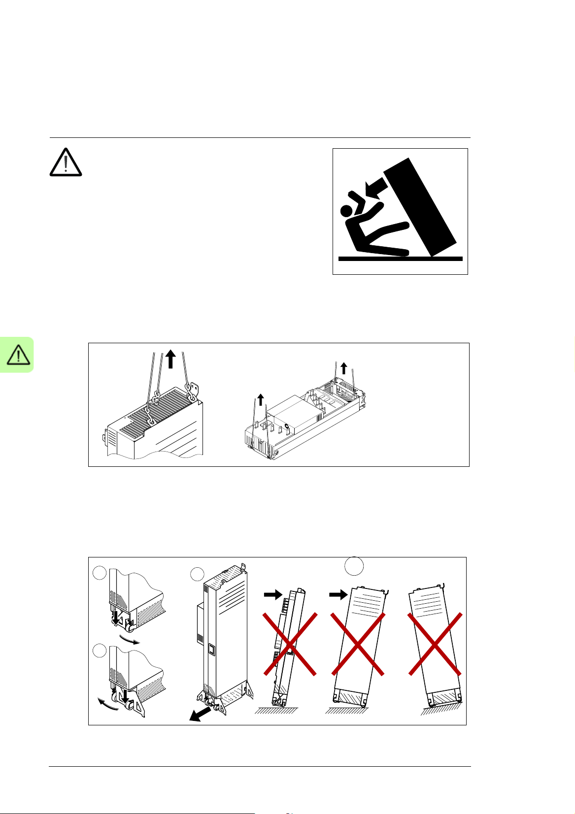
WARNING! Obey these instructions. If you ignore
them, injury or death, or damage to the equipment
can occur.
• Secure the cabinet to the floor (see chapter
Mechanical installation) to prevent it from toppling over
when you pull out the module. The drive module is
heavy and has a high center of gravity.
• Wear protective gloves and long sleeves. Some parts
have sharp edges.
• Handle the drive module carefully:
• Use safety shoes with a metal toe cap to avoid foot injury.
• For frames R10 and R11:
• Lift the module with a lifting device only. Use the designated lifting points.
• Make sure that the module does not topple over when you move it on the floor:
Extend the support legs by pressing each leg a little down (1, 2) and turning it
aside. Whenever possible secure the module also with chains.
• Do not tilt the drive module (A). It is heavy and its center of gravity is high. The
module overturns from a sideways tilt of 5 degrees. Do not leave the module
unattended on a sloping floor.
Safety instructions 15
• Do not use the module installation ramp with plinth heights which exceed the
maximum height (50 mm [1.97 in]) marked on the ramp.
• Secure the module installation ramp carefully.
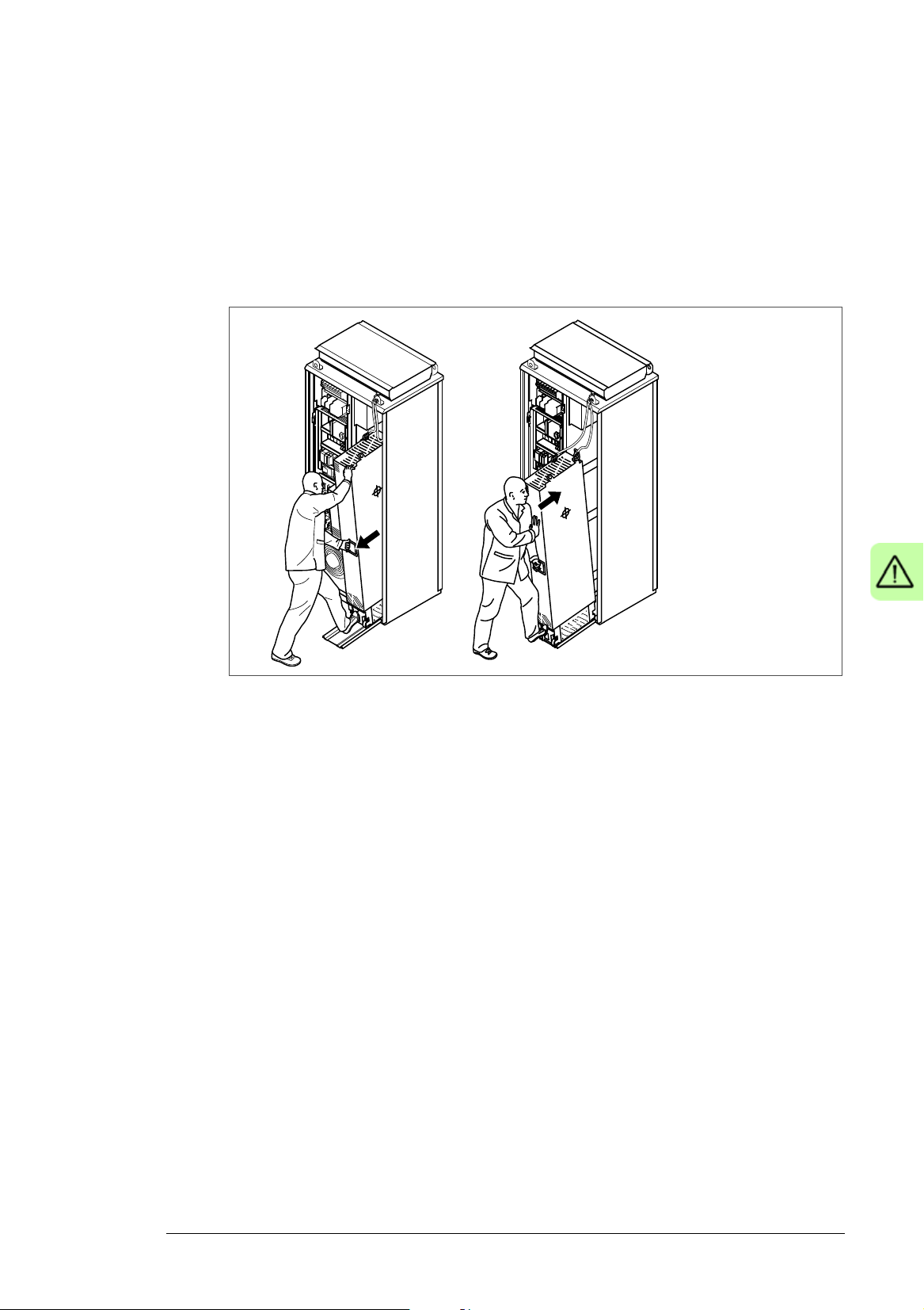
• To prevent the drive module from falling, attach its top lifting lugs with chains to the
cabinet lifting lug before you push the module into the cabinet and pull it from the
cabinet. Work carefully preferably with help from another person as shown below.
Keep a constant pressure with one foot on the base of the module to prevent the
module from falling on its back.
• Beware of hot surfaces. Some parts, such as heatsinks of power semiconductors,
remain hot for a while after disconnection of the electrical supply.
• Keep the drive in its package or protect it otherwise from dust and burr from drilling
and grinding until you install it. Protect also the installed drive against dust and burr.
Electrically conductive debris inside the drive can cause damage or malfunction.
• Vacuum clean the area below the drive before the start-up to prevent the drive cooling
fan from drawing the dust inside the drive.
• Make sure that there is sufficient cooling. See section Examining the installation site
on page 55.
• Before you connect voltage to the drive, make sure that the cabinet doors are closed.
Keep the doors closed during the operation.
• Before you adjust the drive operation limits, make sure that the motor and all driven
equipment can operate throughout the set operation limits.
• Before you activate the automatic fault reset or automatic restart functions of the drive
control program, make sure that no dangerous situations can occur. These functions
reset the drive automatically and continue operation after a fault or supply break.
• The maximum number of drive power-ups is five in ten minutes. Too frequent power-
ups can damage the charging circuit of the DC capacitors.
• Make sure that any safety circuits (for example, emergency stop and Safe torque off)
are validated in start-up. For the Safe torque off, see chapter Safe torque off function
on page 229. For other safety functions, see their separate instructions.
16 Safety instructions
Note:
• If you select an external source for start command and it is on, the drive will start
immediately after fault reset unless you configure the drive for pulse start. See the
firmware manual.
• When the control location is not set to Local, the stop key on the control panel will not
stop the drive.
• Only authorized persons are allowed to repair a malfunctioning drive.
Electrical safety in installation, start-up and maintenance
Precautions before electrical work
These warnings are for all personnel who do work on the drive, motor cable or motor.
WARNING! Obey these instructions. If you ignore them, injury or death, or
damage to the equipment can occur. If you are not a qualified electrician, do not
do installation or maintenance work. Go through these steps before you begin any
installation or maintenance work.
1. Clearly identify the work location.
2. Disconnect all possible voltage sources.
• Open the main switch-disconnector (Q1) of the drive.
• Open the disconnector of the supply transformer as the main switch-disconnector
(Q1) of the drive does not remove the voltage from the input busbars of the drive.
• Make sure that reconnection is not possible. Lock the disconnectors to open
position and attach a warning notice to them.
• Disconnect any external power sources from the control circuits before you do
work on the control cables.
• After you disconnect the drive, always wait 5 minutes to let the intermediate circuit
capacitors discharge before you continue.
3. Protect any other energized parts in the work location against contact.
4. Take special precautions when close to bare conductors.
5. Measure that the installation is de-energized.
• Use a multimeter with an impedance of at least 1 Mohm.
• Make sure that the voltage between the drive input power terminals (L1, L2, L3)
and the grounding (PE) busbar is close to 0 V.
• Make sure that the voltage between the drive module UDC+ and UDC- terminals
and the grounding (PE) busbar is close to 0 V.
6. Install temporary grounding as required by the local regulations.
7. Ask for a permit to work from the person in control of the electrical installation work.

Safety instructions 17
Additional instructions and notes
WARNING! Obey these instructions. If you ignore them, injury or death, or
damage to the equipment can occur.
• If you are not a qualified electrician, do not do installation or maintenance work.
• Do not install a drive with EMC filter option +E200 or +E202 on an ungrounded power
system or a high resistance-grounded (over 30 ohms) power system.
• Do not connect the drive to a voltage higher than what is on the type designation label.
If you do, the brake chopper starts to operate which causes the overheating of the
brake resistor (if present). Overvoltage can also cause the motor to rush to its
maximum speed.
• We do not recommend that you secure the cabinet by arc welding. If you have to, obey
the instructions in section Arc welding on page 69.
• Do not do insulation or voltage withstand tests on the drive or drive modules.
Note:
• The motor cable terminals of the drive are at a dangerous voltage when the input
power is on, regardless of whether the motor is running or not.
• The DC bus and brake resistor terminals (UDC+, UDC-, R+ and R-) are at a
dangerous voltage.
• External wiring can supply dangerous voltages to the terminals of relay outputs
(XRO1, XRO2 and XRO3).
• The Safe torque off function does not remove the voltage from the main and auxiliary
circuits. The function is not effective against deliberate sabotage or misuse.
WARNING! Use a grounding wrist band when you handle the printed circuit
boards. Do not touch the boards unnecessarily. The boards contain components
sensitive to electrostatic discharge.
WARNING! Obey these instructions. If you ignore them, equipment malfunction
and damage to the fiber optic cables can occur.
• Handle the fiber optic cables with care.
• When you unplug the cables, always hold the connector, not the cable itself.
• Do not touch the ends of the fibers with bare hands as the ends are extremely
sensitive to dirt.
• Do not bend the fiber optic cables too tightly. The minimum allowed bend radius is
35 mm (1.4 in).

18 Safety instructions
Grounding
These instructions are for all personnel who are responsible for the grounding of the drive.
WARNING! Obey these instructions. If you ignore them, injury or death and
equipment malfunction can occur, and electromagnetic interference can increase.
• If you are not a qualified electrician, do not do grounding work.
• Always ground the drive, the motor and adjoining equipment. This is necessary for the
personnel safety. Proper grounding also reduces electromagnetic emission and
interference.
• Make sure that the conductivity of the grounding conductors is sufficient. See section
Selecting the power cables on page 78. Obey the local regulations.
• Connect the power cable shields to protective earth (PE) of the drive to make sure of
personnel safety.
• Make a 360° grounding of the power and control cable shields at the cable entries to
suppress electromagnetic disturbances.
• In a multiple-drive installation, connect each drive separately to the protective earth
(PE) busbar of the switch board or the transformer.
Note:
• You can use power cable shields as grounding conductors only when their conductivity
is sufficient.
• As the normal touch current of the drive is higher than 3.5 mA AC or 10 mA DC, you
must use a fixed protective earth connection. See standard EN 61800-5-1, 4.3.5.5.2.

Safety instructions 19
Additional instructions for permanent magnet motor drives
Safety in installation, start-up and maintenance
These are additional warnings concerning permanent magnet motor drives. The other
safety instructions in this chapter are also valid.
WARNING! Obey these instructions. If you ignore them, injury or death and
equipment malfunction can occur.
• Do not do work on the drive when the permanent magnet motor is rotating. A rotating
permanent magnet motor energizes the drive including its input power terminals.
Before installation, start-up and maintenance work on the drive:
• Stop the motor.
• Disconnect the motor from the drive with a safety switch or by other means.
• If you cannot disconnect the motor, make sure that the motor cannot rotate during
work. Make sure that no other system, like hydraulic crawling drives, can rotate the
motor directly or through any mechanical connection like felt, nip, rope, etc.
• Measure that the installation is de-energized.
• Use a multimeter with an impedance of at least 1 Mohm.
• Make sure that the voltage between the drive output terminals (U2, V2, W2) and
the grounding (PE) busbar is close to 0 V.
• Make sure that the voltage between the drive input power terminals (L1, L2, L3)
and the grounding (PE) busbar is close to 0 V.
• Make sure that the voltage between the drive module UDC+ and UDC- terminals
and the grounding (PE) busbar is close to 0 V.
• Install temporary grounding to the drive output terminals (U2, V2, W2). Connect the
output terminals together as well as to the PE.
• Make sure that the operator cannot run the motor over the rated speed. Motor
overspeed causes overvoltage can damage or explode the capacitors in the
intermediate circuit of the drive.

20 Safety instructions

Introduction to the manual 21
2
Introduction to the manual
Contents of this chapter
This chapter describes the manual. It contains a flowchart of steps in checking the
delivery, installing and starting up the drive. The flowchart refers to chapters/sections in
this manual and to other manuals.
Target audience
This manual is intended for people who plan the installation, install, start up, use and
service the drive. Read the manual before you work on the drive. You are expected to
know the fundamentals of electricity, wiring, electrical components and electrical
schematic symbols.
The manual is written for readers worldwide. Both SI and imperial units are shown.
Contents of the manual
This manual contains the instructions and information for the basic drive configuration. The
chapters of the manual are briefly described below.
Safety instructions gives safety instructions for the installation, start-up, operation and
maintenance of the drive.
Introduction to the manual gives an introduction to this manual.
Operation principle and hardware description describes the operation principle and
constructions of the drive.
Mechanical installation describes how to install the drive mechanically.
Guidelines for planning the electrical installation contains instructions for the motor and
cable selection, protections and cable routing.

22 Introduction to the manual
Electrical installation gives instructions on wiring the drive.
Control unit of frames R6 to R9 contains the default I/O connection diagram, descriptions
of the terminals and technical data for the control unit.
Control unit of frames R10 and R11 contains the default I/O connection diagram and
references for the descriptions of the terminals and technical data of the control unit.
Installation checklist contains a list for checking the mechanical and electrical installation
of the drive.
Start-up describes the start-up procedure of the drive.
Fault tracing describes the fault tracing possibilities of the drive.
Maintenance contains preventive maintenance instructions.
Technical data contains the technical specifications of the drive, eg, the ratings, sizes and
technical requirements, provisions for fulfilling the requirements for CE and other
markings.
Dimension drawings contains example dimension drawings of the drive.
Safe torque off function describes the Safe torque off function of the drive and gives
instructions on its implementing.
Resistor braking describes selection, protection and wiring of optional brake choppers and
resistors. The chapter also contains technical data.
Related manuals
See List of related manuals on the inside of the front cover.
Categorization by frame size and option code
Some instructions, technical data and dimension drawings which concern only certain
frame sizes are marked with the symbol of the frame size (R6, R7, R8, R9, R10 or R11)
The frame size is marked on the type designation label, see page 49.
The instructions, technical data and dimension drawings which concern only certain
optional selections are marked with option codes (such as +E205). The options included in
the drive can be identified from the option codes visible on the type designation label. The
option selections are listed in section Type designation key on page 49.
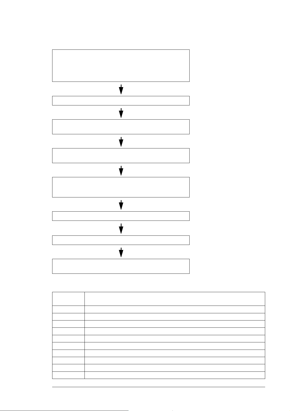
Quick installation, start-up and operating flowchart
Tas k Se e
Plan the electrical installation and acquire the accessories needed
(cables, fuses, etc.).
Check the ratings, required cooling air flow, input power connection,
compatibility of the motor, motor connection, and other technical
data.
Guidelines for planning the
electrical installation (page 71)
Technical data (page 183)
Check the installation site. Ambient conditions (page 207)
Tas k Se e
Introduction to the manual 23
Unpack and check the units (only intact units may be started up).
Examine that all necessary option modules and equipment are
present and correct.
Mount the drive.
Route the cables. Routing the cables (page 83)
Check the insulation of the supply cable, the motor and the motor
cable.
If the drive is about to be connected to an IT (ungrounded) system,
check that the drive is not equipped with EMC filter +E200 or +E202.
Connect the power cables.
Connect the control cables.
Mechanical installation (page 55)
If the drive has been nonoperational for more than one year,
the converter DC link capacitors
need to be reformed (page 180)
Checking the insulation of the
assembly (page 93)
Checking the compatibility with IT
(ungrounded) systems (page 94)
Connecting the power cables (page
96), Connecting the control cables
(page 107),
Check the installation. Installation checklist (page 141)
Start the drive up. Start-up (page 143)
Operate the drive: start, stop, speed control etc. ACS880 quick start-up guide,
firmware manual
Terms and abbreviations
Term/
Abbreviation
EMC Electromagnetic compatibility
EMI Electromagnetic interference
EMT Electrical metallic tubing
FIO-01 Optional digital I/O extension module
FIO-11 Optional analog I/O extension module
FCAN-01 Optional FCAN-01 CANopen adapter module
FCNA-01 Optional ControlNet™ adapter module
FDCO-01 Optional DDCS communication module with two pairs of 10 Mbit/s DDCS channels
FDNA-01 Optional DeviceNet™ adapter module
FECA-01 Optional EtherCAT adapter module
Explanation

24 Introduction to the manual
Term/
Abbreviation
FEPL-01 Optional Ethernet POWERLINK adapter module
FENA-11 Optional Ethernet adapter module for EtherNet/IP™, Modbus TCP and PROFINET IO
FENA-21 Optional Ethernet adapter module for EtherNet/IP™, Modbus TCP and PROFINET IO
FLON-01 Optional LonWorks® adapter module
FPBA-01 Optional PROFIBUS DP adapter module
FEN-01 Optional TTL incremental encoder interface module
FEN-11 Optional TTL absolute encoder interface module
FEN-21 Optional resolver interface module
FEN-31 Optional HTL incremental encoder interface module
FSO-12,
FSO-21
Frame (size) Physical size of the drive
IGBT Insulated gate bipolar transistor; a voltage-controlled semiconductor type widely used in
I/O Input/Output
MCCB Molded case circuit breaker
ZCU Drive control unit. As standard, the external I/O control signals are connected to the control
ZGAB Brake chopper adapter board
ZGAD, BGAD Gate driver adapter board
ZINT Main circuit board
ZMU The memory unit attached to the control unit of the drive
RFI Radio-frequency interference
R6…R11 Frame size designation of the drive
SAR Safe acceleration range
SBC Safe brake control
SLS Safely-limited speed without encoder
SS1 Safe stop 1
SSE Safe stop emergency
SSM Safe speed monitor without encoder
STO Safe torque off
Explanation
protocols
protocols, 2-port
Optional functional safety module
drives due to their easy controllability and high switching frequency.
unit, or optional I/O extensions mounted on it.

Operation principle and hardware description 25
3
Operation principle and hardware description
Contents of this chapter
This chapter briefly describes the operation principle and construction of the drive.
Product overview
The ACS880-07 is an air-cooled cabinet-installed drive for controlling asynchronous AC
induction motors, permanent magnet synchronous motors, AC induction servomotors and
ABB synchronous reluctance motors (SynRM motors) with option N7502.
26 Operation principle and hardware description
L1
L2
L3
Q1
Q2
T21
R12R1 R11T1
>
T
T
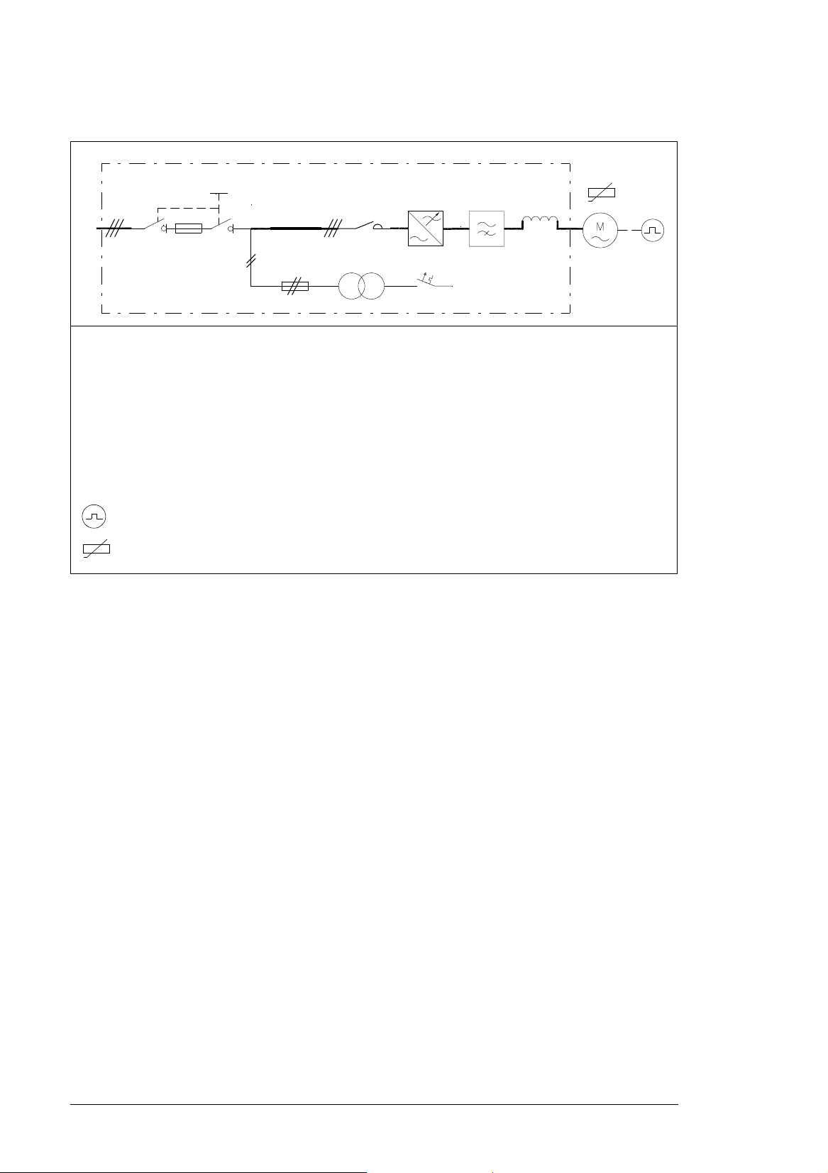
Single-line circuit diagram of the drive
Q1 Main switch-disconnector (switch fuse in frames R6 to R8, switch-disconnector and separate fuses
in frames R9 to R11, or molded case circuit breaker and separate fuses [option +F289 for US
market only])
Q2 Optional line contactor (+F250)
T21 Auxiliary voltage transformer supplying 24 V and 230/115 V control voltage for, eg, cabinet fan(s),
control devices and I/O extension adapter module.
T1 Drive module
R11 Optional common mode filter (+E208)
R12 Optional du/dt filter (+E205) or sine filter (+E206)
HTL pulse encoder for optional FEN-31 HTL incremental encoder interface module (+L205)
PTC sensors for optional thermistor relay(s) (+L205, +2L205) or Pt100 sensors for optional Pt100
relays (+xL206)
Operation principle and hardware description 27
1 2 3
4
5
T1
B
A
6
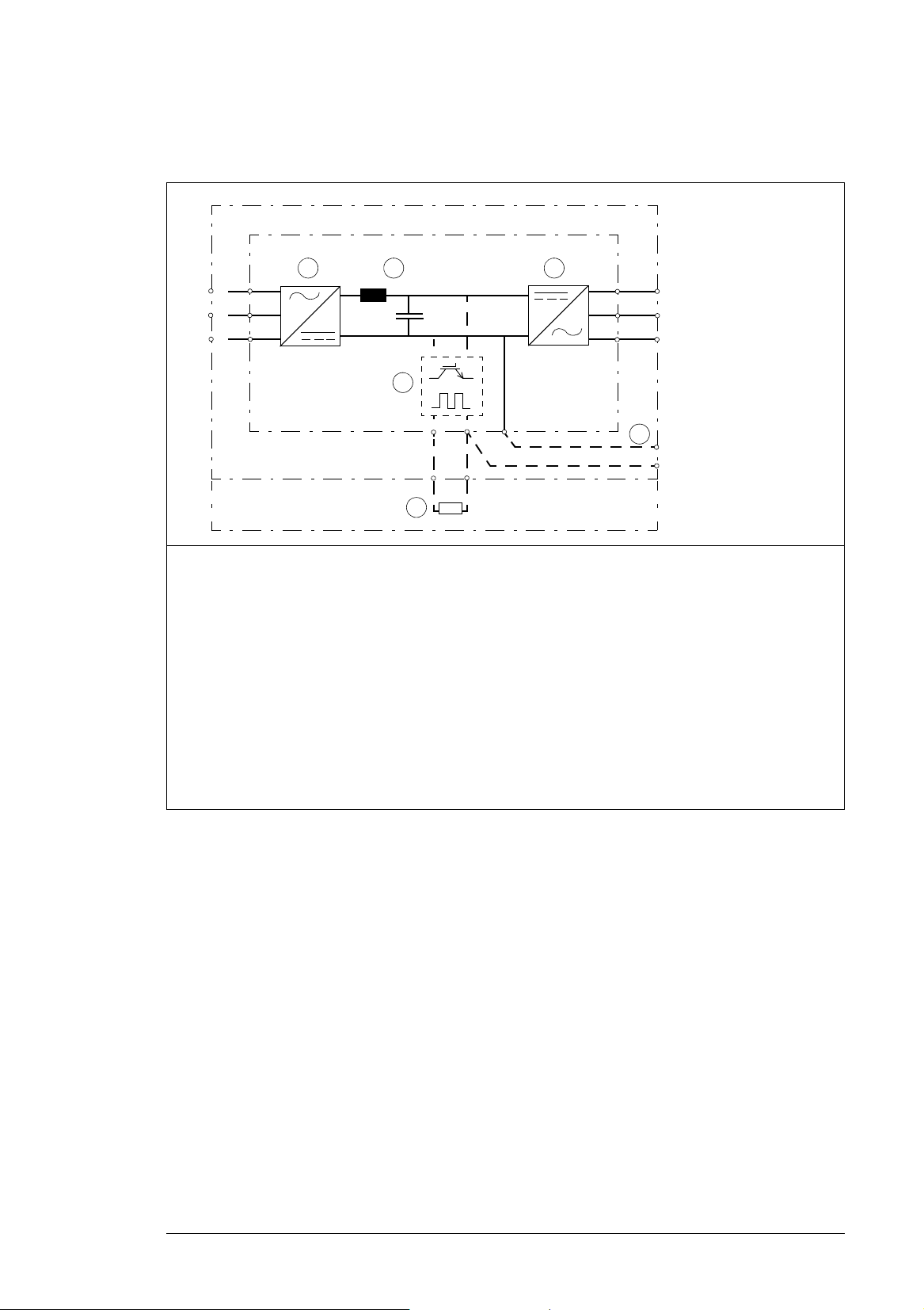
Block diagram of the brake and DC options (+D150, +D151 and
+H356)
A Drive module cubicle
T1 Drive module
B Brake resistor cubicle
1 Rectifier. Converts alternating current and voltage to direct current and voltage.
2 DC link. DC circuit between rectifier and inverter. DC choke is included in frames R6 to R9. An AC
input choke is included in frames R10 and R11.
3 Inverter. Converts direct current and voltage to alternating current and voltage.
4 Brake chopper (option +D150). Conducts the surplus energy from the intermediate DC circuit of the
drive to the brake resistor when necessary. The chopper operates when the DC link voltage exceeds a
certain maximum limit. The voltage rise is typically caused by deceleration (braking) of a high inertia
motor. User obtains and installs the brake resistor when needed.
5 Brake resistor (option +D151)
6 Optional DC cable connection busbars (+H356). Not available with option +D150.
28 Operation principle and hardware description
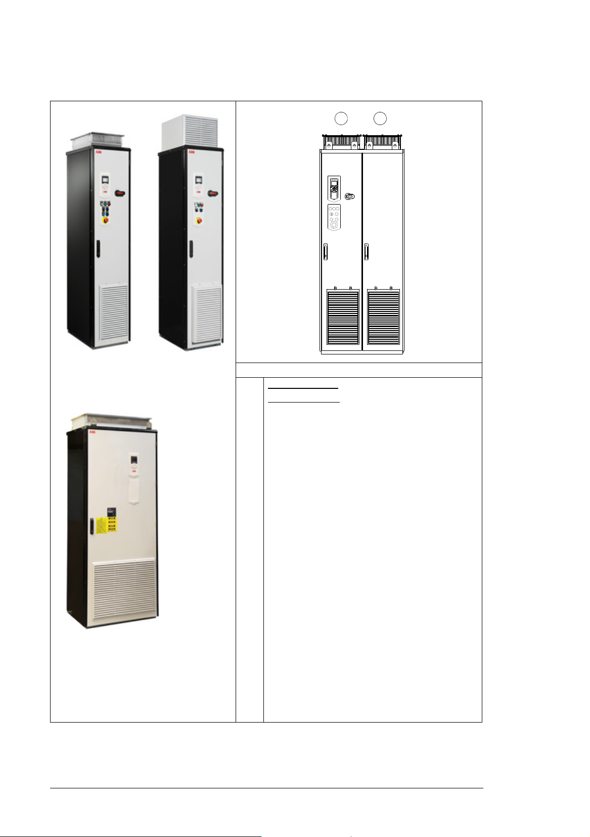
IP22/IP42 IP54
UL Type 1 with molded case circuit
breaker (option +F289 for US market
only)
UL Type 1 /
UL Type 1 Filtered
UL Type 12
12
General information on the cabinet layout
Example cabinet line-up
1 Frames R6 to R8:
Frame
s R9 to R11: two cubicles with one door (main
switch and power cabling cubicle and drive module
cubicle)
2 Brake resistor cubicle with option +D151
drive module cubicle.
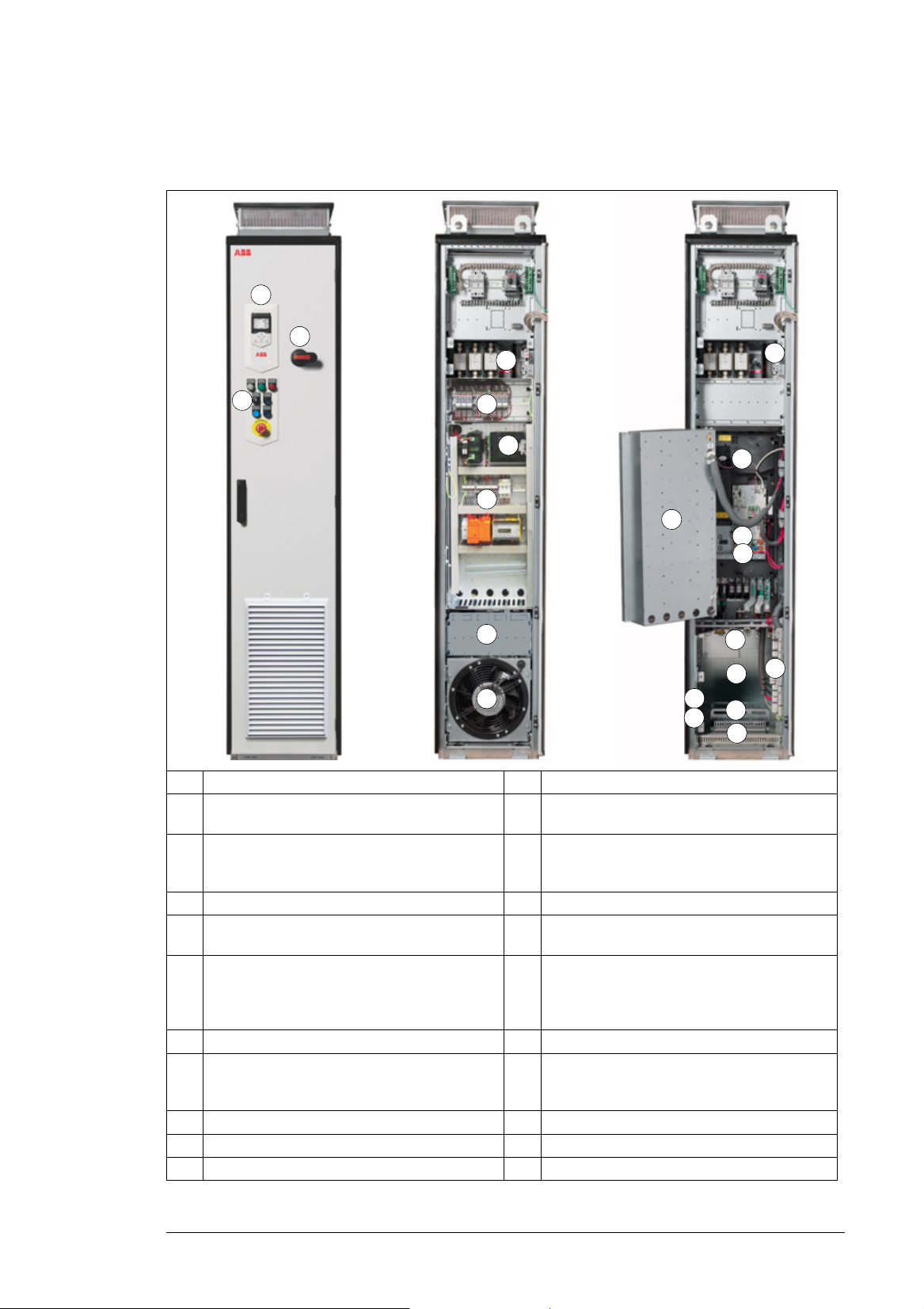
Operation principle and hardware description 29
4
7
12
13
14
1
2
3
7
16
20
10
15
17
8
6
18
9
19
11
5
7
6
Cabinet layout of frames R6 to R8
The cabinet layout without shrouds is shown below.
1 Drive control panel 12 Control unit, see page 125.
2 Door switches and lights, see page 42. 13 Optional terminal block for external control unit
3 Main switch handle 14 Power cable connection terminals and du/dt
4 Main switch-disconnector with fuses
5 Thermistor and Pt100 relays (options +L505
and +L506)
6 Buffering module C22 16 Connection terminals for options +F250,
7 Swing-out frame 17 Cabinet heater (option +G300)
8 Mounting plate with connection terminals for
options +G300, +G307, +G313 at the back side
of the plate
9 “Door” fan 19 Power cable lead-throughs
10 Auxiliary voltage transformer (T21) 20 Control cable lead-through
11 Drive module - -
connections (X504, option +L504)
filter (option +E205) and common mode filter
(option +E208) behind
15 Common mode filter (option +E208)
+Q951, +Q952, +Q963, +Q964+Q968,
+Q954, +M600…+M605,+ L505, +L506. See
page 41.
18 PE busbar
30 Operation principle and hardware description
9
12
16
17
1
2
3
18
8
19
13
10
14
15
11
4
6 7
5
12
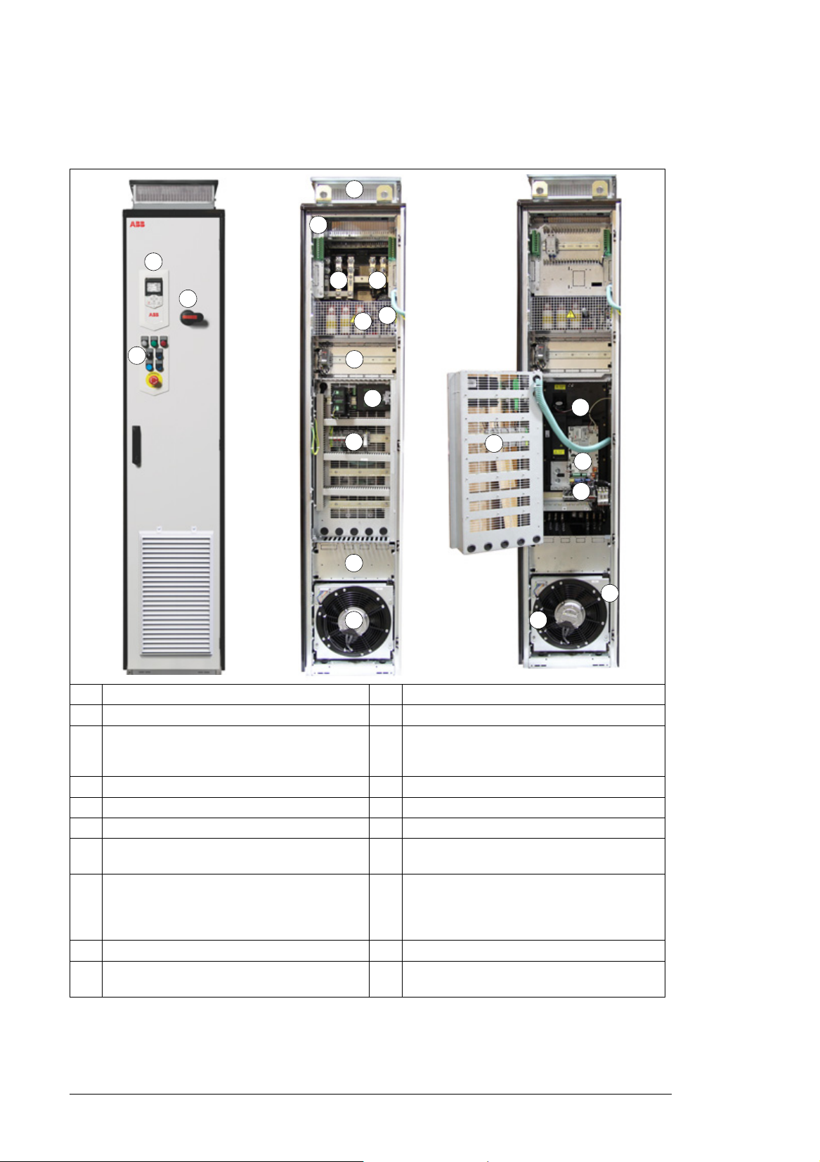
Cabinet layout of frames R6 to R8 with option +C129
The cabinet layout without shrouds is shown below.
1 Drive control panel 11 Buffering module C22
2 Door switches and lights, see page 42. 12 Swing-out frame
3 Main switch handle 13 Mounting plate with connection terminals for
4 Power and control cable lead-throughs 14 “Door” fan
5 Ground bar 15 Drive module
6 Input cable connection terminals 16 Control unit, see page 125.
7 Motor cable connection terminals 17 Optional terminal block for external control unit
8 Auxiliary voltage transformer (T21) 16 Connection terminals for options +F250,
9 Main switch-disconnector with fuses 19 Cabinet heater (option +G300)
10 Thermistor and Pt100 relays (options +L505
and +L506)
options +G300, +G307, +G313 at the back
side of the plate
connections (X504, option +L504)
+Q951, +Q952, +Q963, +Q964+Q968,
+Q954, +M600…+M605,+ L505, +L506. See
page 41.
--
Loading...