


6410
Table of contents
 Loading...
Tropos® Networks Mesh Router
Outdoor Installation Guide
Models 6410 and 6420
ABB
555 Del Rey A ve.
Sunnyvale, CA 94085 USA
www.abb.com/tropos
408-331-6800
Part No. 200566-00 Rev A0
2014_11-06

Copyright Notice
©2003-2014 ABB Tropos W i reless Research Center. All rights reserved. Tropos, Tropos Networks, PWRP,
MetroMesh, and GridCom are registered trademarks of ABB Tropos Wireless Research Center. All other brand
names, company names, product names, trademarks, and registered trademarks are the property of their respective
holder(s). Information contained herein is subject to change without notice. The only warranties for Tropos products
and services are set forth in the express warranty statements accompanying such products and services. Nothing
herein should be construed as constituting an additional warranty. Tropos shall not be liable for technical or editorial
errors or omissions contained herein.
This product includes technology protected by U.S. Patents 6,704,301; 6,965,575; 7,016,328; 7,031,293; 7,058,021;
7,362,737; 7,376,087; 7,382,778; 7,397,789; 7,450,552; 7,460,489; 7,489,932; 7,499,409; 7,505,426; 7,542,421;
7,551,562; 7,564,781; 7,564,862; 7,580,393, 7,580,705; 7,586,879; 7,649,866; 7,668,137; 7,688,808; 7,689,224;
7,697,504; 7,706,285; 7,720,499; 7,729,278; 7,769,040; 7,843,891; 7,924,749; 7,929,975; 7,957,337; 7,970,394;
7,983,225; 8,031,615; 8,036,130; 8,036,186; 8,054,784; 8,055,759; 8,064,404
FCC Notice to Users and Operators
This device complies with Part 15 of the FCC Rules. Operation is subject to the following two conditions: (1) this
device may not cause harmful interference, and (2) this device must accept any interference received, including
interference that may cause undesired operation.
This equipment has been tested and found to comply with the limits for a Class B digital device, pursuant to Part 15 of
the FCC Rules. These limits are designed to provide reasonable protection against harmful interference when the
equipment is operated in a commercial environment. This equipment generates, uses, and can radiate radio frequency
energy and, if not installed and used in accordance with the instruction manual, may cause harmful interference to
radio communications. Operation of this equipment in a residential area is likely to cause harmful interference, in
which case the user will be required to correct the interference at his own expense. If this equipment does cause
interference to radio or television reception, which can be determined b y tur ning the equ ipment off and on, the user is
encouraged to correct the interference by using one of the following measures:
Reorient or relocate the receiving antenna.
Increase separation between the equipment and receiver.
Connect the equipment to an outlet on a circuit different from that to which the receiver is connected.
Consult the dealer or an experienced radio/TV technician.
This Part 15 radio device operates on a non-interference basis with other devices operating at this frequency. Any
changes or modification to said product not expressly approved by Tropos Networks could void the user's authority to
operate this device.
5.8 GHz Point-to-Point and Point-to-Multipoint Systems
Operation of this device in point-to-multipoint systems is limited by federal regulation to
36 dBm EIRP. Unit conducted power in the 5.8 GHz band should be adjusted such that the sum of
conducted power and antenna gain does not exceed 36 dBm EIRP.
The maximum antenna gain for point-to-point operation is 19 dBi. The effective EIRP limit for point-topoint system is 45 dBm EIRP.
Industry Canada
Notice to users and operators:
This Class B digital apparatus meets all requirements of the Canadian Interference Causing Equipment Regulations.
Operation is subject to the following two conditions: (1) this device may not cause harmful interference, and (2) this
device must accept any interference received, including interference that may cause undesired operation.
Tropos Routers Installation Guide, Models 6410 and 6420 2

Cet appareillage numérique de la classe B répond à toutes les exigences de l’interférence canadienne causant des
réglements d’équipement. L’opération est sujette aux deux conditions suivantes : (1) cet dispositif peut ne pas causer
l'interférence nocive, et (2) ce dispositif doit accepter n’importe quelle interférence reçue, y compris l'interférence qui
peut causer l’opération peu désirée.
This device has been designed to operate with the antennas listed in Chapter 6, “Antenna Information.”
Antennas not included in the chapter or having a gain greater than 12 dBi in the 2.4 GHz band and 19 dBi
in the 5.8 GHz band are strictly prohibited for use with this device. The required antenna impedance is 50
ohms.
Operation is subject to the following two conditions:
1. This device may not cause interference, and
2. This device must accept any interference, including interference that may cause undesired operation of the
device.
T o reduce potential radio interference to other users, the antenna type and its gain should be so chosen that
the equivalent isotropically radiated power (EIRP) is not more than that permitted for successful
communication.
European Union WEEE Notice
For EU member countries, this symbol means: Do not dispose of this equipment as unsorted
municipal waste. This equipment must be collected separately.
The return and collection of this product has not been defined at this time, please contact Tropos
Networks for return and/or collection.
It is important for users of this equipment to participate in reuse, recycling, and other forms of
recovery. Th e potential ef fe cts on the environment and human health as a result of the presence of
hazardous substances in electrical and electronic equipment are a waste of natural resources and
cause pollution.
Tropos Routers Installation Guide, Models 6410 and 6420 3
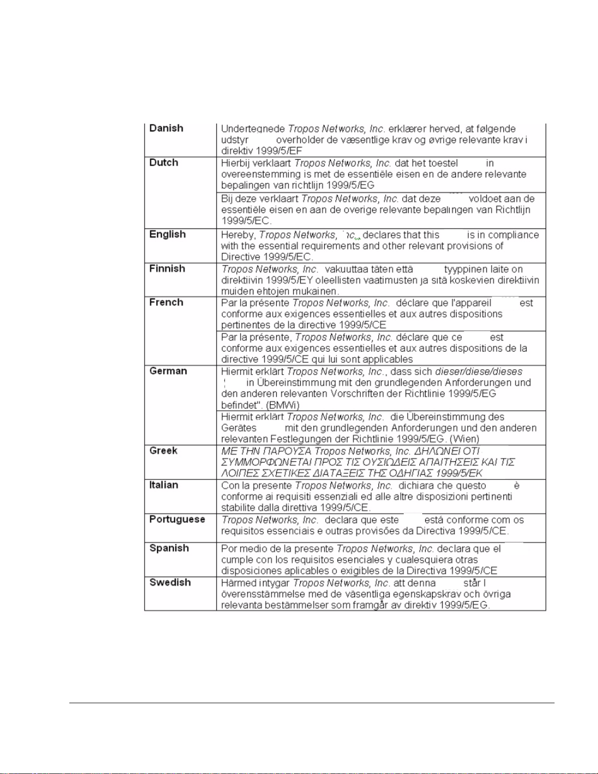
European Community Language Versions o f Informal Stat ement for Inclusion
6410
6420
6410
6420
6410
6420
6410
6420
6410
6420
6410
6420
6410
6420
6410
6420
6410
6420
6410
6420
6410
6420
6410
6420
6410
6420
6410
6420
.
in User Information
The following statements are in accordance with Article 6.3 of Directive 1999/5/EC.
Tropos Routers Installation Guide, Models 6410 and 6420 4
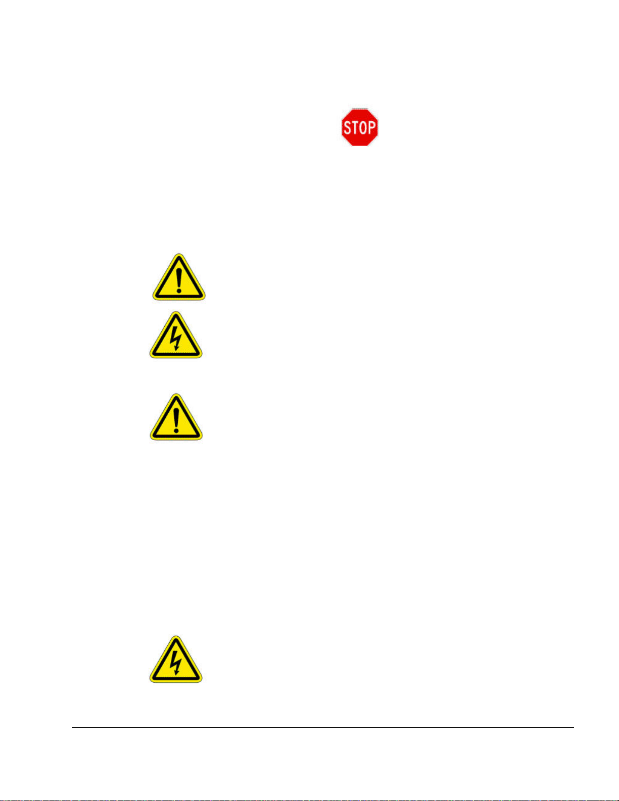
STOP!! STOP!! STOP!! STOP!!
READ THIS FIRST!
Important Safety Instructions
The exclamation point within an equilateral triangle is intended to alert the user
to the presence of important operating and maintenance (servicing) instructions
in the literature accompanying the product.
The lightning flash with an arrowhead symbol within an equilateral triangle is intended
to alert the user to the presence of uninsulated “dangerous voltage” within the product’s
enclosure that may be of sufficient magnitude to constitute a risk of electric shock to
persons.
Caution
Warning
Read these instructions.
Keep these instructions.
Heed all warnings.
Follow all instructions.
Do not defeat the safety purpose of the grounding.
Only use attachments/accessories specified by the manufacturer.
Refer all servicing to qualified service personnel. Servicing is required when the
apparatus has been damage in any way, such as power-supply cord or plug is damaged,
liquid has been spilled on objects have fallen into the apparatus, the apparatus has been
exposed to rain or moisture, does not operate normally, or has been dropped.
Risk of personal injury or death when installing this device!
There is a risk of personal injury or death if the router antennas come near electric power
lines. Carefully read and follow all instructions in this manual. By nature of the
Tropos Routers Installation Guide, Models 6410 and 6420 5
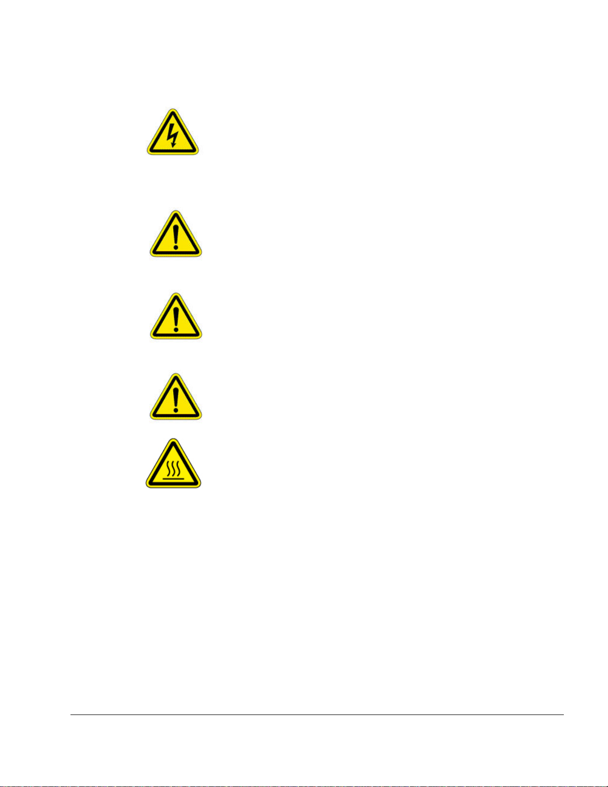
installation, you may be exposed to hazardous environments and high voltage. Use caution when
installing the outdoor system.
This apparatus must be connected to earth ground.
Do not open the unit — risk of electric shock inside.
Risque d'électrocution. Ne pas ouvrir l'unité.
Caution
You are cautioned that any change or modification not expressly approved in this
manual could void your authority to operate this equipment.
Les changements et modifications, non expressément approuvés dans le présent manuel,
peuvent entraîner une interdiction d'utiliser cet appareil pour l'utilisateur.
Service
There are no user-serviceable parts inside. All service must be performed by qualified
personnel.
Vous ne devez pas réparer les pièces se trouvant à l'intérieur de l'appareil. Les réparations
doivent être effectuées uniquement par du personnel qualifié.
The Tropos 6410 and 6420 routers are installed in wet, outdoor locations. Make sure
closure caps are installed and all cable connections are securely fastened and
waterproofed.
Surfaces may become hot. Use caution when accessing the Tropos 6410 and 6420
routers.
Tropos Routers Installation Guide, Models 6410 and 6420 6

Contents
1 Introduction . . . . . . . . . . . . . . . . . . . . . . . . . . . . . . . . . . . . . . . . . . . . . . . . . 11
Tropos 6410 Router Product Summary . . . . . . . . . . . . . . . . . . . . . . 11
Tropos 6420 Router Product Summary . . . . . . . . . . . . . . . . . . . . . . 12
2 Installing the Router . . . . . . . . . . . . . . . . . . . . . . . . . . . . . . . . . . . . . . . . . . 14
Preparing for Installation . . . . . . . . . . . . . . . . . . . . . . . . . . . . . . . . . 14
Installation Hardware and Tools . . . . . . . . . . . . . . . . . . . . . . . . . . 16
Site Planning . . . . . . . . . . . . . . . . . . . . . . . . . . . . . . . . . . . . . . . . . 16
Location Guidelines . . . . . . . . . . . . . . . . . . . . . . . . . . . . . . . . . . . 17
Site Surveys . . . . . . . . . . . . . . . . . . . . . . . . . . . . . . . . . . . . . . . . . 17
Safety . . . . . . . . . . . . . . . . . . . . . . . . . . . . . . . . . . . . . . . . . . . . . . 17
Mounting Strategies . . . . . . . . . . . . . . . . . . . . . . . . . . . . . . . . . . . . . 18
Proper Use of Clamps . . . . . . . . . . . . . . . . . . . . . . . . . . . . . . . . . . . 19
Pole, Tower, and Streetlight Mounting Instructions . . . . . . . . . . . . . 20
Metal Pole Mounting . . . . . . . . . . . . . . . . . . . . . . . . . . . . . . . . . . . 21
Wood Pole Mounting . . . . . . . . . . . . . . . . . . . . . . . . . . . . . . . . . . 24
Wood Brace Mounting . . . . . . . . . . . . . . . . . . . . . . . . . . . . . . . . . 26
Tower Mounting . . . . . . . . . . . . . . . . . . . . . . . . . . . . . . . . . . . . . . 27
Streetlight Mounting . . . . . . . . . . . . . . . . . . . . . . . . . . . . . . . . . . . 28
Connecting Data and Power Cables . . . . . . . . . . . . . . . . . . . . . . . . 29
Ethernet Ports . . . . . . . . . . . . . . . . . . . . . . . . . . . . . . . . . . . . . . . . 32
Serial Ports . . . . . . . . . . . . . . . . . . . . . . . . . . . . . . . . . . . . . . . . . . 32
Grounding the Router . . . . . . . . . . . . . . . . . . . . . . . . . . . . . . . . . . . 34
Grounding the Data Protection Device . . . . . . . . . . . . . . . . . . . . . 35
Safety and Servicing Information . . . . . . . . . . . . . . . . . . . . . . . . . . . 36
RF Exposure Information . . . . . . . . . . . . . . . . . . . . . . . . . . . . . . . 36
Safety Guidelines . . . . . . . . . . . . . . . . . . . . . . . . . . . . . . . . . . . . . 36
Servicing the Router . . . . . . . . . . . . . . . . . . . . . . . . . . . . . . . . . . . 37
3 Installing Battery and Power Backup Accessories . . . . . . . . . . . . . . . . . 38
Introduction . . . . . . . . . . . . . . . . . . . . . . . . . . . . . . . . . . . . . . . . . . . 38
Installing the PS079001 . . . . . . . . . . . . . . . . . . . . . . . . . . . . . . . . . . 40
Installing the Battery Backup Unit . . . . . . . . . . . . . . . . . . . . . . . . . . 44
Tropos Routers Installation Guide, Models 6410 and 6420 7

4 Power Consumption . . . . . . . . . . . . . . . . . . . . . . . . . . . . . . . . . . . . . . . . . . 48
5 Product Specifications . . . . . . . . . . . . . . . . . . . . . . . . . . . . . . . . . . . . . . . . 50
6 Antenna Information . . . . . . . . . . . . . . . . . . . . . . . . . . . . . . . . . . . . . . . . . . 57
2.4 GHz Antennas . . . . . . . . . . . . . . . . . . . . . . . . . . . . . . . . . . . . . . 58
5 GHz Antenna . . . . . . . . . . . . . . . . . . . . . . . . . . . . . . . . . . . . . . . . 59
Abbreviations . . . . . . . . . . . . . . . . . . . . . . . . . . . . . . . . . . . . . . . . . . . . . . . . 60
Index . . . . . . . . . . . . . . . . . . . . . . . . . . . . . . . . . . . . . . . . . . . . . . . . . . . . . . . 63
Tropos Routers Installation Guide, Models 6410 and 6420 8

List of Figures
FIGURE 1 Tropos 6410/ 6420 Router Exploded View . . . . . . . . . . . . . . . . . . . 15
FIGURE 2 Example Mounting Location - Antennas Facing Upward . . . . . . . . . 18
FIGURE 3 Proper Use of the Clamps . . . . . . . . . . . . . . . . . . . . . . . . . . . . . . . . 19
FIGURE 4 Metal Pole Mounting . . . . . . . . . . . . . . . . . . . . . . . . . . . . . . . . . . . . 21
FIGURE 5 Placing the Router on the Mounting Assembly . . . . . . . . . . . . . . . . 23
FIGURE 6 Wood Pole Mounting . . . . . . . . . . . . . . . . . . . . . . . . . . . . . . . . . . . . 24
FIGURE 7 Wood Brace Mounting Option . . . . . . . . . . . . . . . . . . . . . . . . . . . . . 26
FIGURE 8 Tower Mounting . . . . . . . . . . . . . . . . . . . . . . . . . . . . . . . . . . . . . . . . 27
FIGURE 9 Streetlight Mounting . . . . . . . . . . . . . . . . . . . . . . . . . . . . . . . . . . . . . 28
FIGURE 10 Routing the Data/Power Cable to the Router . . . . . . . . . . . . . . . . . 31
FIGURE 11 Data Port Connection . . . . . . . . . . . . . . . . . . . . . . . . . . . . . . . . . . . 31
FIGURE 12 Grounding Arrangement . . . . . . . . . . . . . . . . . . . . . . . . . . . . . . . . . 34
FIGURE 13 Grounding the Indoor Network Protection Unit . . . . . . . . . . . . . . . . 35
FIGURE 14 Deployment Scenarios . . . . . . . . . . . . . . . . . . . . . . . . . . . . . . . . . . . 39
FIGURE 15 Co-Mounting the PS079001 with the Router . . . . . . . . . . . . . . . . . . 41
FIGURE 16 Mounting the PS079001 on a Metal Pole . . . . . . . . . . . . . . . . . . . . 42
FIGURE 17 Mounting the PS079001 on a Wood Pole . . . . . . . . . . . . . . . . . . . . 43
FIGURE 18 Co-Mounting the BBU with the Router . . . . . . . . . . . . . . . . . . . . . . . 45
FIGURE 19 Remote Mounting the BBU on a Metal Pole . . . . . . . . . . . . . . . . . . 46
FIGURE 20 Mounting the BBU on a Wood Pole . . . . . . . . . . . . . . . . . . . . . . . . . 47
FIGURE 21 6410 Power Consumption . . . . . . . . . . . . . . . . . . . . . . . . . . . . . . . . 48
FIGURE 22 6420 Power Consumption . . . . . . . . . . . . . . . . . . . . . . . . . . . . . . . . 49
FIGURE 23 2.4 GHz Antenna Patterns . . . . . . . . . . . . . . . . . . . . . . . . . . . . . . . . 58
FIGURE 24 5 GHz Antenna Patterns . . . . . . . . . . . . . . . . . . . . . . . . . . . . . . . . . 59
Tropos Routers Installation Guide, Models 6410 and 6420 9

List of Tables
TABLE 1 6410 Router Models . . . . . . . . . . . . . . . . . . . . . . . . . . . . . . . . . . . . 11
TABLE 2 6420 Router Models . . . . . . . . . . . . . . . . . . . . . . . . . . . . . . . . . . . . 13
TABLE 3 Ethernet Port Pin Assignments . . . . . . . . . . . . . . . . . . . . . . . . . . . . 32
TABLE 4 Serial Client Scenarios . . . . . . . . . . . . . . . . . . . . . . . . . . . . . . . . . . 32
TABLE 5 Pin Assignments for RJ-45 MGT Port - Serial Clients . . . . . . . . . . . 33
TABLE 6 RF Exposure Information . . . . . . . . . . . . . . . . . . . . . . . . . . . . . . . . . 36
TABLE 7 Ordering Information . . . . . . . . . . . . . . . . . . . . . . . . . . . . . . . . . . . . 39
TABLE 8 6410 Power Consumption (Watts) at Specified Input Voltage . . . . . 48
TABLE 9 6420 Power Consumption (Watts) at Specified Input Voltage . . . . . 49
TABLE 10 Physical Specifications . . . . . . . . . . . . . . . . . . . . . . . . . . . . . . . . . . 50
TABLE 11 Interfaces . . . . . . . . . . . . . . . . . . . . . . . . . . . . . . . . . . . . . . . . . . . . . 52
TABLE 12 Power Options / Consumption . . . . . . . . . . . . . . . . . . . . . . . . . . . . . 54
TABLE 13 Certifications, Other . . . . . . . . . . . . . . . . . . . . . . . . . . . . . . . . . . . . . 54
TABLE 14 PS079001 - Outdoor PoE Injector, non-photocell . . . . . . . . . . . . . . 55
TABLE 15 BB063001 - External Battery Backup Unit . . . . . . . . . . . . . . . . . . . . 55
TABLE 16 Abbreviations . . . . . . . . . . . . . . . . . . . . . . . . . . . . . . . . . . . . . . . . . . 60
Tropos Routers Installation Guide, Models 6410 and 6420 10

1 Introduction
This guide explains how to install the Tropos® 6410 and 6420 Mesh routers safely and is
intended for trained technical professionals.
This chapter covers the following topics:
“Tropos 6410 Router Product Summary ” on page 11
“Tropos 6420 Router Product Summary ” on page 12
Tropos 6410 Router Product Summary
The Tropos 6410 router has the following characteristics:
802.11b/g/n band, 2400-2483 MHz
Support for 802.11b/g/n clients
PoE power input: The Tropo s 6410 and 6420 routers are DC po wered. There are a number of
methods for connecting power that are described in detail later in this installation manual.
Tropos 6410 and 6420 routers can be powered using:
— 802.3at compliant power applied to the 10/100/1000Base-T (LAN) port
— 11-55VDC power applied to the 10/100Base-T (MGT) port
2 Ethernet ports
— One LAN port for network backhaul communications; this port is a 10/100/1000Base-T
Ethernet port.
— One MGT port for connecting a wired client device; this is either a 10/100BaseT
Ethernet port or a serial port depending on the product. See the model nu mbers in the
following table. The serial or Ethernet port is factory-installed and cannot be changed in
the field.
Table 1 lists the Tropos 6410 router models.
TABLE 1 6410 Router Models
Model Description
64103000 6410: 2.4GHz; 10/100/1000Base-T + 10/100Base-T; FCC markets
64103000G 6410: 2.4GHz; 10/100/1000Base-T + 10/100Base-T; FCC markets; GPS
64103060 6410: 2.4GHz; 10/100/1000Base-T + serial; FCC markets
64103060G 6410: 2.4GHz; 10/100/1000Base-T + serial; FCC markets; GPS
64103002 6410: 2.4GHz; 10/100/1000Base-T + 10/100Base-T; ETSI markets
Tropos Routers Installation Guide, Models 6410 and 6420 11

Chapter 1
TABLE 1 6410 Router Models (continued)
Model Description
64103002G 6410: 2.4GHz; 10/100/1000Base-T + 10/100Base-T; ETSI markets; GPS
64103062 6410: 2.4GHz; 10/100/1000Base-T + serial; ETSI markets
64103062G 6410: 2.4GHz; 10/100/1000Base-T + serial; ETSI markets; GPS
64103003 6410: 2.4GHz; 10/100/1000Base-T + 10/100Base-T; Global-A markets
64103003G 6410: 2.4GHz; 10/100/1000Base-T + 10/100Base-T; Global-A markets; GPS
64103063 6410: 2.4GHz; 10/100/1000Base-T + serial; Global-A markets
64103063G 6410: 2.4GHz; 10/100/1000Base-T + serial; Global-A markets; GPS
64103004 6410: 2.4GHz; 10/100/1000Base-T + 10/100Base-T; Global-B markets
64103004G 6410: 2.4GHz; 10/100/1000Base-T + 10/100Base-T; Global-B markets; GPS
64103064 6410: 2.4GHz; 10/100/1000Base-T + serial; Global-B markets
64103064G 6410: 2.4GHz; 10/100/1000Base-T + serial; Global-B markets; GPS
Tropos 6420 Router Product Summary
The Tropos 6420 router has the following characteristics:
802.11a/b/g/n dual band, 2400-2483 MHz/5470-5850 MHz
Support for 802.11a/b/g/n clients
PoE power input: The Tropo s 6410 and 6420 routers are DC po wered. There are a number of
methods for connecting power that are described in detail later in this installation manual.
Tropos 6410 and 6420 routers can be powered using:
— 802.3at compliant power applied to the 10/100/1000Base-T (LAN) port
— 11-55VDC power applied to the 10/100Base-T (MGT) port
2 Ethernet ports
— One LAN port for network backhaul communications; this port is a 10/100/1000Base-T
Ethernet port (Gigabit Ethernet).
— One MGT port for connecting a wired client device; this is either a 10/100BaseT
Ethernet port or a serial port depending on the product. See the model nu mbers in the
following table. The serial or Ethernet port is factory-installed and cannot be changed in
the field.
Tropos Routers Installation Guide, Models 6410 and 6420 12

Chapter 1
Table 2 lists the Tropos 6420 router models.
TABLE 2 6420 Router Models
Model Description
64203000 6420: 2.4GHz + 5GHz; 10/100/1000Base-T + 10/100Base-T; FCC markets
64203000G 6420: 2.4GHz + 5GHz; 10/100/1000Base-T + 10/100Base-T; FCC markets; GPS
64203060 6420: 2.4GHz + 5GHz; 10/100/1000Base-T + serial; FCC markets
64203060G 6420: 2.4GHz + 5GHz; 10/100/1000Base-T + serial; FCC markets; GPS
64203002 6420: 2.4GHz + 5GHz; 10/100/1000Base-T + 10/100Base-T; ETSI markets
64203002G 6420: 2.4GHz + 5GHz; 10/100/1000Base-T + 10/100Base-T; ETSI markets; GPS
64203062 6420: 2.4GHz + 5GHz; 10/100/1000Base-T + serial; ETSI markets
64203062G 6420: 2.4GHz + 5GHz; 10/100/1000Base-T + serial; ETSI markets; GPS
64203003 6420: 2.4GHz + 5GHz; 10/100/1000Base-T + 10/100Base-T; Global-A markets
64203003G 6420: 2.4GHz + 5GHz; 10/100/1000Base-T + 10/100Base-T; Global-A markets;
GPS
64203063 6420: 2.4GHz + 5GHz; 10/100/1000Base-T + serial; Global-A markets
64203063G 6420: 2.4GHz + 5GHz; 10/100/1000Base-T + serial; Global-A markets; GPS
64203004 6420: 2.4GHz + 5GHz; 10/100/1000Base-T + 10/100Base-T; Global-B markets
64203004G 6420: 2.4GHz + 5GHz; 10/100/1000Base-T + 10/100Base-T; Global-B markets;
GPS
64203064 6420: 2.4GHz + 5GHz; 10/100/1000Base-T + serial; Global-B markets
64203064G 6420: 2.4GHz + 5GHz; 10/100/1000Base-T + serial; Global-B markets; GPS
Tropos Routers Installation Guide, Models 6410 and 6420 13

2 Installing the Router
Note
This chapter covers the following topics:
“Preparing for Installation” on page 14
“Mounting Strategies” on page 18
“Proper Use of Clamps” on page 19
“Pole, Tower, and Streetlight Mounting Instructions” on page 20
“Connecting Data and Power Cables” on page 29
“Grounding the Router” on page 34
“Safety and Servicing Information” on page 36
Preparing for Installation
The Tropos 6410 and 6420 routers must be installed by a trained professional, value added
reseller, or systems integrator who is familiar with RF planning issues and regulatory limits
defined by the governing body of the country in which the unit will be installed. This section
explains how to prepare the installation site.
An exploded view of the router assembly is shown in Figure 1.
Operating the unit with non-qualified antennas is a violation of U.S. FCC Rules Part 15.203(c), Code of
Federal Regulations, Title 47.
Tropos Routers Installation Guide, Models 6410 and 6420 14
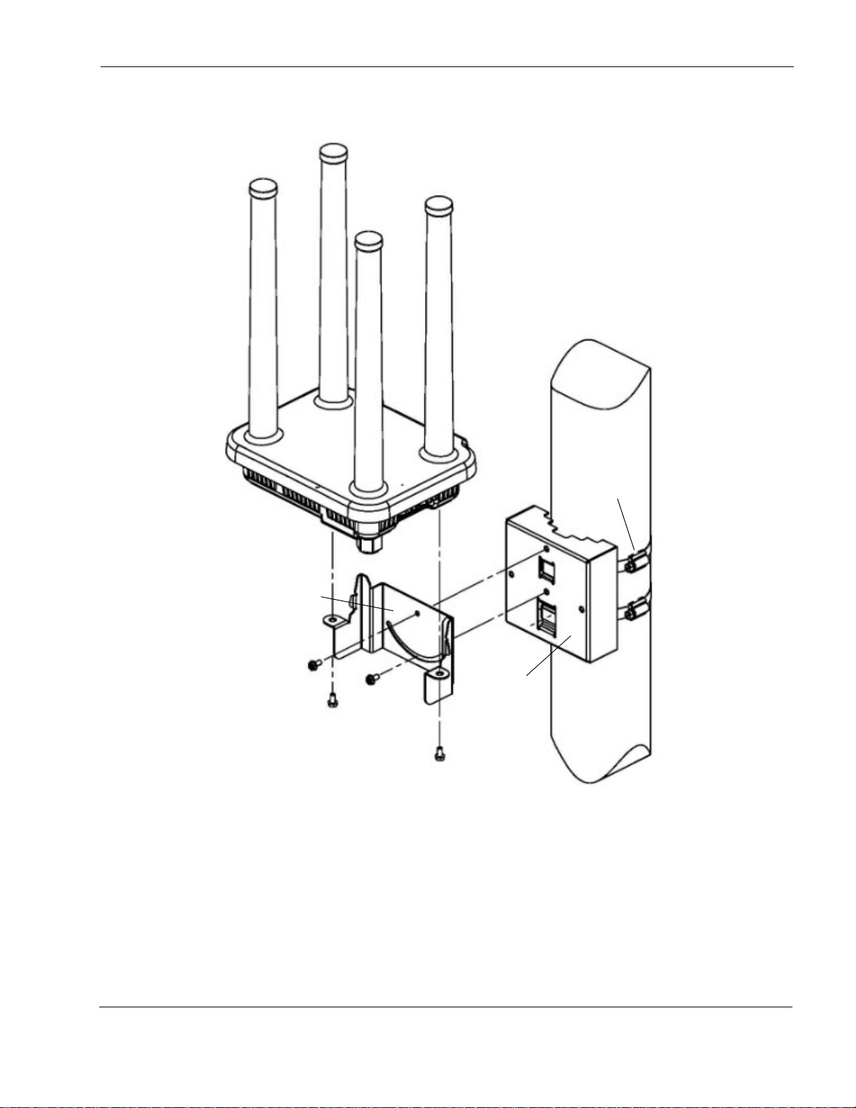
FIGURE 1 Tropos 6410/ 6420 Router Exploded View
2.4 GHz Tx/Rx
2.4 GHz Tx/Rx
5 GHz Tx/Rx
5 GHz
Clamps
Pole
Mounting bracket
Tx/Rx
bracket
Router
Chapter 2
Tropos Routers Installation Guide, Models 6410 and 6420 15

Installation Hardware and Tools
Note
Note
The following installation accessories are included in the shipping package:
One pole bracket
Two 4-inch diameter clamps
Two 6-inch diameter clamps
Five 5/16-inch #10-32 stainless steel hex head machine screws
You must supply the following tools:
Level
5/16-inch nut driver
1/4-inch flat blade screwdriver
Tower mounting only: stainless or galvanized steel pipe and 1/2-inch or
5/8-inch nuts, bolts, and washers to connect to the tower arm.
Wood pole mounting only: one 1/4-inch diameter, 3 1/2-inch long lag bolt
Site Planning
To ensure safe and durable wiring, router installation must follow appropriate electrical and
building codes. Follow all local codes and regulations. For example in the U.S., follow the
National Electrical Code (NEC) requirements, unless local codes in your area take precedence
over the NEC code.
Chapter 2
The maximum length of Cat 5 cable for 10BaseT, 10/100BaseT , and 10/100/1000BaseT Ethernet
connections is 300 feet (90 meters).
The Ethernet duplex and speed setting is configurable.
The U.S. National Electrical Codes (NEC) Article 800 requires the use of Agency Listed (UL/CSA/TUV)
Building Entrance Protector for all power and data communications cables entering a building. The NEC
intends by Article 800 to protect the building and occupants from fires caused by transient voltage and
current surges.
Ethernet data cable installations having lengths greater th an 140 fee t in the outdo or environment mu st use
a UL497 approved (UL/CSA/TUV Listed) primary protection device at the building entrance. Ethernet data
cable installations having lengths less than 140 feet in the outdoor environment may use a UL497A (UL/
CSA/TUV Listed) secondary protection device at the building entrance. Tropos Data Protection Device and
Network Protection Units are UL497A secondary protection devices.
Tropos Routers Installation Guide, Models 6410 and 6420 16

Location Guidelines
Tropos routers are radio devices and therefore susceptible to interference that can reduce
throughput and range. Follow these guidelines to ensure the best performance:
Install the unit in an area where trees, buildings, and large steel structures do not obstruct
radio signals to and from the antenna. Direct line-of-sight operation is best.
Install the unit away from possible sources of 2.4 GHz and 5 GHz interference, such as
cordless phones, wireless cameras, frequency hopping (FHSS) and DSSS LAN transceivers
(non-802.11), electronic news gathering video links, radars, amateur radios, land mobile
radio services, local government sites (such as law enforcement), fixed microwave services,
local TV transmission, and private fixed point transmitters.
Site Surveys
Due to variations in component configuration, placement, and physical environment, each
installation is unique. Before installing routers, perform a site survey to determine the optimum
placement of units for maximum range, coverage, and network performance. Consider the
following factors when performing a site survey:
Data rates—Sensitivity and range are inversely proportional to data bit rates. The maximum
radio range is achieved at the lowest workable data rate. A decrease in receiver threshold
sensitivity occurs as radio data rate increases.
Antenna orientation—Proper antenna orientation is a critical factor in maximizing radio
range. As a general rule, range increases in proportion to gain and antenna height measured
from the ground. The Tropos 6410 and 6420 routers have integrated antennas; therefore,
antenna location and orientation depend on the location of the unit.
Physical environment—Clear or open areas provide better radio range than closed or filled
areas. The less cluttered the operating environment, the greater the range.
Obstructions—A physical obstruction, such as a building or tree, can block or hinder
communication. A void locating antennas in a location where there is an obstruction between
sending and receiving devices.
Building materials—Radio penetration is influenced by the building material used in
construction. For example, drywall construction permits greater range than concrete blocks.
Chapter 2
Safety
Installing the routers can pose a serious hazard. Be sure to take precautions to avoid the
following:
Exposure to high voltage lines during installation
Falls when working at heights or with ladders
Injuries from dropping tools and equipment
Contact with AC power wiring
Tropos Routers Installation Guide, Models 6410 and 6420 17
Mounting Strategies
Note
When choosing mounting locations, consider the available mounting structures and antenna
clearance. The router should always be mounted with the top of the unit horizontal and level and
with the antennas facing upward.
It is usually best to attach ground and data cables to the router prior to mounting. Before
mounting the router, review the wiring instructions in “Grounding the Router” on page 34 and
“Connecting Data and Power Cables” on page 29 to determine the best strategy for the selected
location.
To eliminate potential interference from the mounting structure, the router should be mounted
with at least 4 feet of clearance around the antennas.
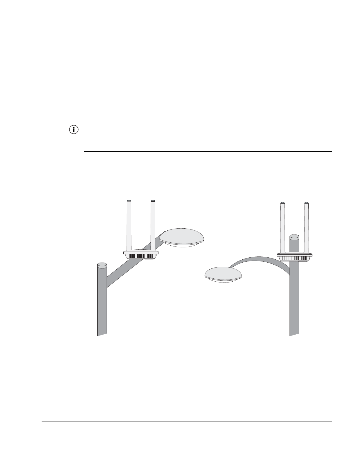
Acceptable options for mounting on a streetlight are shown in Figure 2. In each case the router is
mounted to assure clearance for the antennas above the height of the streetlight.
FIGURE 2 Example Mounting Location - Antennas Facing Upward
Chapter 2
Antennas clear of obstruction
Antennas clear
of obstruction
Tropos Routers Installation Guide, Models 6410 and 6420 18
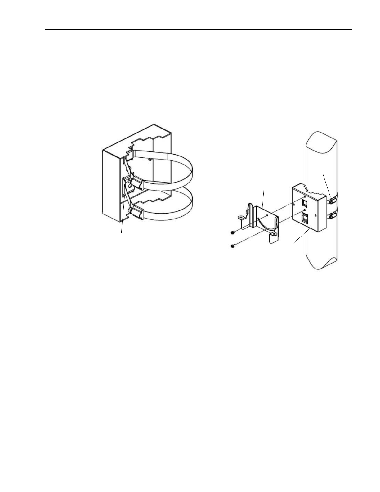
Proper Use of Clamps
Band goes
behind inner tabs
Clamps
Pole
Mounting bracket
bracket
The mounting assembly contains two clamps to secure the router to the mounting structure.
Figure 3 illustrates the proper use of the clamps. The clamps must be routed through slots in the
pole bracket as shown in the figure, and then attached to the pole and tightened.
The pole bracket should be leveled before it is secured to the pole.
FIGURE 3 Proper Use of the Clamps
Chapter 2
Tropos Routers Installation Guide, Models 6410 and 6420 19

Pole, Tower, and Streetlight Mounting Instructions
Note
Note
Note
This section explains how to mount the router on a pole, tower, or streetlight. It is best to mount
the router to aluminum or galvanized steel structures. The mounting brackets are designed to
pierce any oxidation layers that are on the outside of the pole, thereby assuring good quality
connection to the grounded structure.
Due to potential antenna obstruction issues, the router is not designed to be directly mounted on
a building wall. If it is necessary to mount the router on a wall, follow the instructions for
mounting on a wooden pole (“Wood Pole Mounting” on page 24), and attempt to mount the
router with maximum possible clearance around the antennas.
The router should always be mounted with the top of the router horizontal and level and with the antennas
facing upward.
It is best to attach ground and data cables to the router before sliding the ro ut er in to the mo un tin g bracket,
as explained in this section. Before mounting the router, review the wiring instructions in “Grounding the
Router” on page 34 and “Connecting Data and Power Cables” on page 29 to determine the best strategy
for the selected location.
Chapter 2
Mounting to wood, concrete, or painted poles may require primary grounding for the unit. Check the
national electrical codes in your area for specific rules.
Tropos Routers Installation Guide, Models 6410 and 6420 20
Loading...