


ACS800-07-1850-3
ABB ACS800-07-1850-3, ACS800-07-0870-3, ACS800-07-1230-3, ACS800-07-1030-3, ACS800-07-0760-5 Hardware Manual
...
ACS800
Hardware Manual
ACS800-07 Drives (500 to 2800 kW)
Phone: 800.894.0412 - Fax: 888.723.4773 - Web: www.clrwtr.com - Email: info@clrwtr.com

ACS800 Single Drive Manuals
HARDWARE MANUALS (appropriate manual is included in the
delivery)
ACS800-01/U1 Hardware Manual 0.55 to 160 kW (0.75 to 200 HP)
3AFE64382101 (English)
ACS800-01/U1/04 Marine Supplement 0.55 to 160 kW (0.75 to
200 HP) 3AFE64291275 (English)
ACS800-11/U11 Hardware Manual 5.5 to 110 kW (7.5 to 125 HP)
3AFE68367883 (English)
ACS800-31/U31 Hardware Manual 5.5 to110 kW (7.5 to 125 HP)
3AFE68599954 (English)
ACS800-02/U2 Hardware Manual 90 to 500 kW (125 to 600 HP)
3AFE64567373 (English)
ACS800-04/U4 Hardware Manual 0.55 to 160 kW (0.75 to 200 HP)
3AFE68372984 (English)
ACS800-04/04M/U4 Hardware Manual 45 to 560 kW (60 to
600 HP) 3AFE64671006 (English)
ACS800-04/04M/U4 Cabinet Installation 45 to 560 kW (60 to
600 HP) 3AFE68360323 (English)
ACS800-07/U7 Hardware Manual 45 to 560 kW (50 to 600 HP)
3AFE64702165 (English)
ACS800-07/U7 Dimensional Drawings 45 to 560 kW (50 to
600 HP) 3AFE64775421
ACS800-07 Hardware Manual 500 to 2800 kW
3AFE64731165 (English)
ACS800-17 Hardware Manual 55 to 2500 kW (75 to 2800 HP)
3AFE68397260 (English)
ACS800-37 Hardware Manual 55 to 2700 kW (75 to 3000 HP)
3AFE68557925 (English)
• Safety instructions
• Electrical installation planning
• Mechanical and electrical installation
• Motor control and I/O board (RMIO)
• Maintenance
• Technical data
• Dimensional drawings
• Resistor braking
FIRMWARE MANUALS, SUPPLEMENTS AND GUIDES
(appropriate documents are included in the delivery)
Standard Control Program Firmware Manual
3AFE64527592 (English)
System Application Program Firmware Manual
3AFE64670646 (English)
Application Program Template Firmware Manual
3AFE64616340 (English)
Master/Follower 3AFE64590430 (English)
Pump Control Application Program Firmware Manual
3AFE68478952 (English)
Extruder Control Program Supplement 3AFE64648543 (English)
Centrifuge Control Program Supplement 3AFE64667246 (English)
Traverse Control Program Supplement 3AFE64618334 (English)
Crane Control Program Firmware Manual 3BSE11179 (English)
Adaptive Programming Application Guide
3AFE64527274 (English)
OPTION MANUALS (delivered with optional equipment)
Fieldbus Adapters, I/O Extension Modules etc.
Phone: 800.894.0412 - Fax: 888.723.4773 - Web: www.clrwtr.com - Email: info@clrwtr.com

ACS800-07 Drives
500 to 2800 kW
Hardware Manual
3AFE64731165 REV E EN
EFFECTIVE: 15.2.2008
© 2008 ABB Oy. All Rights Reserved.
Phone: 800.894.0412 - Fax: 888.723.4773 - Web: www.clrwtr.com - Email: info@clrwtr.com

Phone: 800.894.0412 - Fax: 888.723.4773 - Web: www.clrwtr.com - Email: info@clrwtr.com
Update Notice
1
Update Notice
NEW (page 6): Safety / Installation and maintenance work
• After maintaining or modifying a drive safety circuit or changing circuit boards
inside the module, retest the functioning of the safety circuit according to the
start-up instructions.
• Do not change the electrical installations of the drive except for the essential
control and power connections. Changes may affect the safety performance or
operation of the drive unexpectedly. All customer-made changes are on the
customer's responsibility.
[...]
Note:
• The Safe torque off function (option +Q968) does not remove the voltage from the
main and auxiliary circuits.
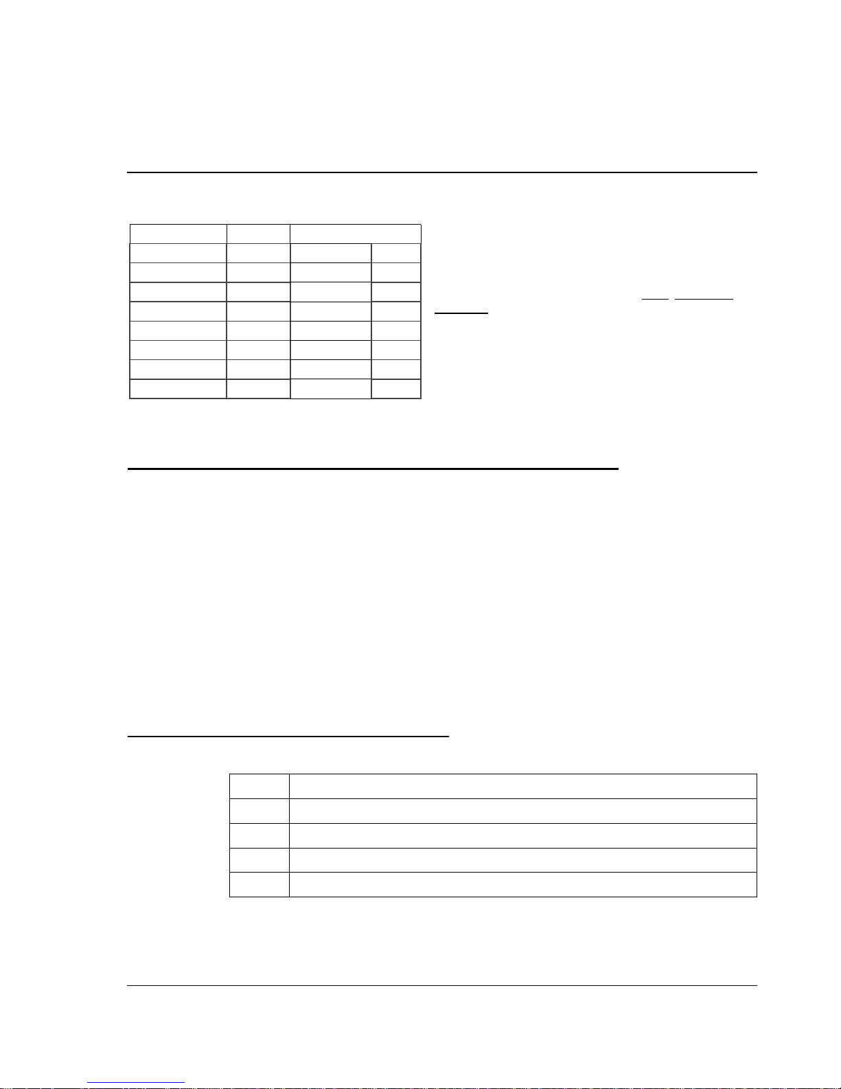
NEW/CHANGED (page 37): Type code
The table below contains the valid option code definitions for the emergency stop.
The notice concerns the following ACS800-07 Drives (500
to 2800 kW) Hardware Manuals:
Code: 3AUA0000059446 Rev A
Valid: from 01.02.2010 until the release of the next revision of
the manual
Contents:
The headings in this update notice refer to the modified
subsections in the original English manual. Each heading also
includes a page number and a classifier NEW
, CHANGED, or
DELETED
. The page number refers to the page number in the
original English manual. The classifier describes the type of
the modification.
Code Description
+Q951 Emergency stop, stop category 0 with opening the main contactor/breaker
+Q952 Emergency stop, stop category 1 with opening the main contactor/breaker
+Q963 Emergency stop, stop category 0 without opening the main contactor/breaker
+Q964 Emergency stop, stop category 1 without opening the main contactor/breaker SS1
Code Revision Language
3AFE64731165 E English EN
3AFE64772911 E German DE
3AFE64772929 E Span ish ES
3AFE64772937 E Finnish FI
3AFE64774239 E French FR
3AFE64772945 E Italian IT
3AFE68588235 E Russian RU
3AFE64772953 E Swedish SV
Phone: 800.894.0412 - Fax: 888.723.4773 - Web: www.clrwtr.com - Email: info@clrwtr.com

Update Notice
2
NEW (page 37): Type code
The table below contains the new option code definition for the Safe torque off
function.
NEW (page 61): Emergency stop
Note: If you add or modify the wiring in the drive safety circuits, ensure that the
appropriate standards (e.g. IEC 61800-5-1, EN 62061, EN/ISO 13849-1 and -2) and
the ABB guidelines are met. After making the changes, verify the operation of the
safety function by testing it.
NEW (page 61): Safe torque off
The drive supports the Safe torque off (STO) function according to standards
EN 61800-5-2:2007; EN/ISO 13849-1:2008, IEC 61508, and EN 62061:2005. The
function also corresponds to an uncontrolled stop in accordance with category 0 of
EN 60204-1 and prevention of unexpected start-up of EN 1037.
The STO may be used where power removal is required to prevent an unexpected
start. The function disables the control voltage of the power semiconductors of the
drive output stage, thus preventing the inverter from generating the voltage required
to rotate the motor (see the diagram below). By using this function, short-time
operations (like cleaning) and/or maintenance work on non-electrical parts of the
machinery can be performed without switching off the power supply to the drive.
Code Description
+Q968 Safe torque off (STO) with a safety relay
Phone: 800.894.0412 - Fax: 888.723.4773 - Web: www.clrwtr.com - Email: info@clrwtr.com

Update Notice
3
Phone: 800.894.0412 - Fax: 888.723.4773 - Web: www.clrwtr.com - Email: info@clrwtr.com

Update Notice
4
WARNING! The Safe torque off function does not disconnect the voltage of the main
and auxiliary circuits from the drive. Therefore maintenance work on electrical parts
of the drive or the motor can only be carried out after isolating the drive system from
the main supply.
Note: The Safe torque off function can be used for stopping the drive in emergency
stop situations. In the normal operating mode, use the Stop command instead. If a
running drive is stopped by using the function, the drive will trip and stop by coasting.
If this is not acceptable, e.g. causes danger, the drive and machinery must be
stopped using the appropriate stopping mode before using this function.
Note concerning permanent magnet motor drives in case of a multiple IGBT
power semiconductor failure: In spite of the activation of the Safe torque off
function, the drive system can produce an alignment torque which maximally rotates
the motor shaft by 180/p degrees. p denotes the pole pair number.
Note: If you add or modify the wiring in the drive safety circuits, ensure that the
appropriate standards (e.g. IEC 61800-5-1, EN 62061, EN/ISO 13849-1 and -2) and
the ABB guidelines are met.
NEW (page 101): On-load checks
The following information has been added to the procedure:
NEW (page 101): On-load checks
The following information has been added to the procedure:
Action Additional information
Check the correct operation of the emergency stop
circuits from each operating location.
If the drive is equipped with the category 1
emergency stop function (option +Q952 or +Q964),
adjust the delay time of the emergency stop relay
and the deceleration time of the drive emergency
stop function. The factory default settings do not
necessarily meet the application needs.
Action Additional information
Check that the Safe torque off function (option
+Q968, if installed) works:
Optional function. See delivery
specific circuit diagrams.
• Ensure that the drive can be run and stopped
freely during the commissioning.
• Stop the drive (if running), switch the input power
off and isolate the drive from the power line by a
disconnector.
• Check the STO circuit connections against the
circuit diagram.
Phone: 800.894.0412 - Fax: 888.723.4773 - Web: www.clrwtr.com - Email: info@clrwtr.com

Update Notice
5
CHANGED (page 115): LEDs
NEW (page 126): Ambient conditions
Cabinets with option +Q968: the installation site altitude in operation is 0 to 2000 m.
• Close the disconnector and switch the power on.
• Test the operation of the STO function when the
motor is stopped:
- Give a stop command for the drive (if running)
and wait until the motor shaft is at standstill.
- Activate the STO circuit and give a start
command for the drive.
- Ensure that the motor stays at standstill.
- Deactivate the STO circuit.
• Restart the drive and check that the motor runs
normally.
• Test the operation of the STO function when the
motor is running:
- Start the drive and ensure that the motor is
running.
- Activate the STO circuit.
- Ensure that the motor stops and the drive trips.
- Reset the fault and try to start the drive.
- Ensure that the motor stays at standstill.
- Deactivate the STO circuit.
• Restart the drive and check that the motor runs
normally.
LED Indication
V309 (red) Prevention of unexpected start (option +Q950) or Safe torque off (option +Q968) is
ON.
Operation
installed for stationary use
Installation site altitude
[...]
Cabinets with option +Q968:
0 to 2000 m
Action Additional information
Phone: 800.894.0412 - Fax: 888.723.4773 - Web: www.clrwtr.com - Email: info@clrwtr.com

Update Notice
6
Phone: 800.894.0412 - Fax: 888.723.4773 - Web: www.clrwtr.com - Email: info@clrwtr.com
Safety instructions
5
Safety instructions
What this chapter contains
This chapter contains safety instructions you must follow when installing, operating
and servicing the drive. If ignored, physical injury or death may follow, or damage
may occur to the drive, the motor or driven equipment. Read the safety instructions
before you work on the unit.
Usage of warnings and notes
There are two types of safety instructions throughout this manual: warnings and
notes. Warnings caution you about conditions which can result in serious injury or
death and/or damage to the equipment, and advise on how to avoid the danger.
Notes draw attention to a particular condition or fact, or give information on a
subject. The warning symbols are used as follows:
Dangerous voltage warning warns of high voltages which can cause
physical injury and/or damage to the equipment.
General warning warns about conditions, other than those caused by
electricity, which can result in physical injury and/or damage to the
equipment.
Electrostatic discharge warning warns of electrostatic discharge which
can damage the equipment.
Phone: 800.894.0412 - Fax: 888.723.4773 - Web: www.clrwtr.com - Email: info@clrwtr.com

Safety instructions
6
Installation and maintenance work
These warnings are intended for all who work on the drive, motor cable or motor.
Ignoring the instructions can cause physical injury or death, or damage the
equipment.
WARNING!
•
Only qualified electricians are allowed to install and maintain the drive.
•
The main switch on the cabinet door does not remove the voltage from the input
busbars of the drive. Before working on the drive, isolate the whole drive from
the supply.
•
Never work on the drive, the motor cable or the motor when main power is
applied. After switching off the input power, always wait for 5 min to let the
intermediate circuit capacitors discharge before you start working on the drive,
the motor or the motor cable. Measure the voltage between terminals UDC+
and UDC- (L+ and L–) with a multimeter (impedance at least 1 Mohm) to
ensure that the drive is discharged before beginning work.
•
Apply temporary grounding before working on the unit.
•
Do not work on the control cables when power is applied to the drive or to the
external control circuits. Externally supplied control circuits may cause
dangerous voltages to exist inside the drive even when the main power of the
drive is switched off.
•
Do not make any insulation or voltage withstand tests on the drive or drive
modules.
•
When reconnecting the motor cable, always check that the phase order is
correct.
•
When joining shipping splits (if any), check the cable connections at the joints
before switching on the supply voltage.
•
Live parts on the inside of the doors are protected against direct contact.
Special attention shall be paid when handling metallic shrouds.
Note:
•
The motor cable terminals on the drive are at a dangerously high voltage when
the input power is on, regardless of whether the motor is running or not.
•
The brake control terminals (UDC+, UDC-, R+ and R- terminals) carry a
dangerous DC voltage (over 500 V).
•
Depending on the external wiring, dangerous voltages (115 V, 220 V or 230 V)
may be present on the relay outputs of the drive system.
•
The Prevention of Unexpected Start function does not remove the voltage from
the main and auxiliary circuits.
Phone: 800.894.0412 - Fax: 888.723.4773 - Web: www.clrwtr.com - Email: info@clrwtr.com

Safety instructions
7
WARNING!
•
During the installation procedure, the inverter modules may have to be
temporarily extracted from the cabinet. The modules have a high centre of
gravity. In order to minimise the danger of toppling over, keep the support legs
of the modules extended whenever manoeuvring the modules outside the
cabinet.
•
Electrically conductive dust inside the unit may cause damage or lead to
malfunction. Make sure that dust from drilling does not enter the drive when
installing.
•
Fastening the cabinet by riveting or welding is not recommended. However, if
welding is necessary, ensure the return wire is properly connected in order not
to damage the electronic equipment in the cabinet. Also ensure that welding
fumes are not inhaled.
•
Ensure sufficient cooling of the unit.
•
Cooling fans may continue to rotate for a while after the disconnection of the
electrical supply.
•
Some parts inside the drive cabinet, such as heatsinks of power
semiconductors, remain hot for a while after the disconnection of the electrical
supply.
WARNING!
•
The printed circuit boards contain components sensitive to electrostatic
discharge. Wear a grounding wrist band when handling the boards. Do not
touch the boards unnecessarily.
Phone: 800.894.0412 - Fax: 888.723.4773 - Web: www.clrwtr.com - Email: info@clrwtr.com

Safety instructions
8
Grounding
These instructions are intended for all who are responsible for the grounding of the
drive. Incorrect grounding can cause physical injury, death or equipment malfunction
and increase electromagnetic interference.
Fibre optic cables
WARNING!
•
Ground the drive, the motor and adjoining equipment to ensure personnel
safety in all circumstances, and to reduce electromagnetic emission and pickup.
•
Make sure that grounding conductors are adequately sized as required by
safety regulations.
•
In a multiple-drive installation, connect each drive separately to protective
earth (PE).
•
Do not install a drive equipped with an EMC (line) filter to an ungrounded
power system or a high resistance-grounded (over 30 ohms) power system.
Note:
•
Power cable shields are suitable for equipment grounding conductors only
when adequately sized to meet safety regulations.
•
As the normal leakage current of the drive is higher than 3.5 mA AC or 10 mA
DC (stated by EN 50178, 5.2.11.1), a fixed protective earth connection is
required.
WARNING!
•
Handle the fibre optic cables with care. When unplugging optic cables, always
grab the connector, not the cable itself. Do not touch the ends of the fibres with
bare hands as the fibre is extremely sensitive to dirt. The minimum allowed
bend radius is 35 mm (1.4”).
Phone: 800.894.0412 - Fax: 888.723.4773 - Web: www.clrwtr.com - Email: info@clrwtr.com
Safety instructions
9
Operation
These warnings are intended for all who plan the operation of the drive or operate
the drive. Ignoring the instructions can cause physical injury or death or damage the
equipment.
WARNING!
•
If the drive is equipped with an optional brake unit, make sure there are
inverters connected to the intermediate circuit before start. As a rule of thumb,
the sum capacitance of the inverters connected must be at least 30% of the
sum capacitance of all inverters.
•
Close the switch fuses of all parallel-connected inverters before start.
•
Do not open the DC switch fuse of an inverter when the inverter is running.
WARNING!
•
Before adjusting the drive and putting it into service, make sure that the motor
and all driven equipment are suitable for operation throughout the speed range
provided by the drive. The drive can be adjusted to operate the motor at
speeds above and below the speed provided by connecting the motor directly
to the power line.
•
Do not activate automatic fault reset functions of the Standard Application
Program if dangerous situations can occur. When activated, these functions
will reset the drive and resume operation after a fault.
•
Do not control the motor with the disconnecting device (means); instead, use
the control panel keys and , or commands via the I/O board of the drive.
The maximum allowed number of charging cycles of the DC capacitors (i.e.
power-ups by applying power) is five in ten minutes.
Note:
•
If an external source for start command is selected and it is ON, the drive (with
Standard Application Program) will start immediately after fault reset unless the
drive is configured for 3-wire (a pulse) start/stop.
•
When the control location is not set to Local (L not shown in the status row of
the display), the stop key on the control panel will not stop the drive. To stop
the drive using the control panel, press the LOC/REM key and then the stop
key .
Phone: 800.894.0412 - Fax: 888.723.4773 - Web: www.clrwtr.com - Email: info@clrwtr.com

Safety instructions
10
Permanent magnet motor drives
These are additional warnings concerning permanent magnet motor drives.
WARNING! Do not work on the drive when the permanent magnet motor is rotating.
Also when the supply power is switched off, a rotating permanent magnet motor
feeds power to the intermediate circuit of the drive and also the supply connections
become live (even when the inverter is stopped!).
Installation and maintenance work
• Disconnect the motor from the drive with a safety switch
and additionally, if possible,
• lock the motor shaft and ground the motor connection terminals temporarily by
connecting them together as well as to the PE.
Operation
Do not run the motor above the rated speed. Motor overspeed leads to overvoltage
which may result in explosion of the capacitors in the intermediate circuit of the drive.
Application program
Controlling a permanent magnet motor is only allowed using the ACS800 Permanent
Magnet Synchronous Motor Drive Application Program, or using other application
programs in scalar control mode only.
Phone: 800.894.0412 - Fax: 888.723.4773 - Web: www.clrwtr.com - Email: info@clrwtr.com

Table of contents
11
Table of contents
ACS800 Single Drive Manuals . . . . . . . . . . . . . . . . . . . . . . . . . . . . . . . . . . . . . . . . . . . . . . . . . . . . . 2
Safety instructions
What this chapter contains . . . . . . . . . . . . . . . . . . . . . . . . . . . . . . . . . . . . . . . . . . . . . . . . . . . . . . . . 5
Usage of warnings and notes . . . . . . . . . . . . . . . . . . . . . . . . . . . . . . . . . . . . . . . . . . . . . . . . . . . . . . 5
Installation and maintenance work . . . . . . . . . . . . . . . . . . . . . . . . . . . . . . . . . . . . . . . . . . . . . . . . . . 6
Grounding . . . . . . . . . . . . . . . . . . . . . . . . . . . . . . . . . . . . . . . . . . . . . . . . . . . . . . . . . . . . . . . . 8
Fibre optic cables . . . . . . . . . . . . . . . . . . . . . . . . . . . . . . . . . . . . . . . . . . . . . . . . . . . . . . . . . . . 8
Operation . . . . . . . . . . . . . . . . . . . . . . . . . . . . . . . . . . . . . . . . . . . . . . . . . . . . . . . . . . . . . . . . . . . . . . 9
Permanent magnet motor drives . . . . . . . . . . . . . . . . . . . . . . . . . . . . . . . . . . . . . . . . . . . . . . . . . . . 10
Installation and maintenance work . . . . . . . . . . . . . . . . . . . . . . . . . . . . . . . . . . . . . . . . . . . . . 10
Operation . . . . . . . . . . . . . . . . . . . . . . . . . . . . . . . . . . . . . . . . . . . . . . . . . . . . . . . . . . . . . . . . 10
Application program . . . . . . . . . . . . . . . . . . . . . . . . . . . . . . . . . . . . . . . . . . . . . . . . . . . . . . . . 10
Table of contents
About this manual
What this chapter contains . . . . . . . . . . . . . . . . . . . . . . . . . . . . . . . . . . . . . . . . . . . . . . . . . . . . . . . 17
Target audience . . . . . . . . . . . . . . . . . . . . . . . . . . . . . . . . . . . . . . . . . . . . . . . . . . . . . . . . . . . . . . . 17
Common chapters for multiple products . . . . . . . . . . . . . . . . . . . . . . . . . . . . . . . . . . . . . . . . . . . . . 17
Categorization according to the frame size . . . . . . . . . . . . . . . . . . . . . . . . . . . . . . . . . . . . . . . . . . . 17
Contents . . . . . . . . . . . . . . . . . . . . . . . . . . . . . . . . . . . . . . . . . . . . . . . . . . . . . . . . . . . . . . . . . . . . . 17
Installation and commissioning flowchart . . . . . . . . . . . . . . . . . . . . . . . . . . . . . . . . . . . . . . . . . . . . 18
Product and service inquiries . . . . . . . . . . . . . . . . . . . . . . . . . . . . . . . . . . . . . . . . . . . . . . . . . . . . . 19
Product training . . . . . . . . . . . . . . . . . . . . . . . . . . . . . . . . . . . . . . . . . . . . . . . . . . . . . . . . . . . . . . . . 19
Providing feedback on ABB Drives manuals . . . . . . . . . . . . . . . . . . . . . . . . . . . . . . . . . . . . . . . . . . 19
Terms and abbreviations . . . . . . . . . . . . . . . . . . . . . . . . . . . . . . . . . . . . . . . . . . . . . . . . . . . . . . . . . 20
Hardware description
What this chapter contains . . . . . . . . . . . . . . . . . . . . . . . . . . . . . . . . . . . . . . . . . . . . . . . . . . . . . . . 21
The ACS800-07 . . . . . . . . . . . . . . . . . . . . . . . . . . . . . . . . . . . . . . . . . . . . . . . . . . . . . . . . . . . . . . . . 21
Cabinet line-up . . . . . . . . . . . . . . . . . . . . . . . . . . . . . . . . . . . . . . . . . . . . . . . . . . . . . . . . . . . . 21
Swing-out frame . . . . . . . . . . . . . . . . . . . . . . . . . . . . . . . . . . . . . . . . . . . . . . . . . . . . . . 23
Cabling direction . . . . . . . . . . . . . . . . . . . . . . . . . . . . . . . . . . . . . . . . . . . . . . . . . . . . . . 24
Single-line circuit diagram of the drive . . . . . . . . . . . . . . . . . . . . . . . . . . . . . . . . . . . . . . . . . . . . . . 25
Controls . . . . . . . . . . . . . . . . . . . . . . . . . . . . . . . . . . . . . . . . . . . . . . . . . . . . . . . . . . . . . . . . . . . . . . 26
Door switches . . . . . . . . . . . . . . . . . . . . . . . . . . . . . . . . . . . . . . . . . . . . . . . . . . . . . . . . . . . . 26
Load switch-disconnector . . . . . . . . . . . . . . . . . . . . . . . . . . . . . . . . . . . . . . . . . . . . . . . 26
Auxiliary voltage switch . . . . . . . . . . . . . . . . . . . . . . . . . . . . . . . . . . . . . . . . . . . . . . . . . 26
Earthing/Grounding switch . . . . . . . . . . . . . . . . . . . . . . . . . . . . . . . . . . . . . . . . . . . . . . 26
Other door controls . . . . . . . . . . . . . . . . . . . . . . . . . . . . . . . . . . . . . . . . . . . . . . . . . . . . 26
Supply unit control electronics . . . . . . . . . . . . . . . . . . . . . . . . . . . . . . . . . . . . . . . . . . . . . . . . 27
Phone: 800.894.0412 - Fax: 888.723.4773 - Web: www.clrwtr.com - Email: info@clrwtr.com

Table of contents
12
Reading and setting of values (page 1 of 2) . . . . . . . . . . . . . . . . . . . . . . . . . . . . . . . . .28
Reading and setting of values (page 2 of 2) . . . . . . . . . . . . . . . . . . . . . . . . . . . . . . . . .29
Terminal blocks . . . . . . . . . . . . . . . . . . . . . . . . . . . . . . . . . . . . . . . . . . . . . . . . . . . . . . .30
Digital input and relay output terminals . . . . . . . . . . . . . . . . . . . . . . . . . . . . . . . . . . . . .31
Emergency stop input . . . . . . . . . . . . . . . . . . . . . . . . . . . . . . . . . . . . . . . . . . . . . . . . . .32
Earth (ground) current function . . . . . . . . . . . . . . . . . . . . . . . . . . . . . . . . . . . . . . . . . . .33
Power loss ride-through function . . . . . . . . . . . . . . . . . . . . . . . . . . . . . . . . . . . . . . . . . .34
Inverter unit control . . . . . . . . . . . . . . . . . . . . . . . . . . . . . . . . . . . . . . . . . . . . . . . . . . . . . . . . .34
Motor control . . . . . . . . . . . . . . . . . . . . . . . . . . . . . . . . . . . . . . . . . . . . . . . . . . . . . . . . . . . . . .35
Reduced run capability . . . . . . . . . . . . . . . . . . . . . . . . . . . . . . . . . . . . . . . . . . . . . . . . . . . . . .35
Type code . . . . . . . . . . . . . . . . . . . . . . . . . . . . . . . . . . . . . . . . . . . . . . . . . . . . . . . . . . . . . . . . . . . . .36
Mechanical installation
What this chapter contains . . . . . . . . . . . . . . . . . . . . . . . . . . . . . . . . . . . . . . . . . . . . . . . . . . . . . . . .39
General . . . . . . . . . . . . . . . . . . . . . . . . . . . . . . . . . . . . . . . . . . . . . . . . . . . . . . . . . . . . . . . . . . . . . . .39
Required tools . . . . . . . . . . . . . . . . . . . . . . . . . . . . . . . . . . . . . . . . . . . . . . . . . . . . . . . . . . . . . . . . .39
Moving the unit . . . . . . . . . . . . . . . . . . . . . . . . . . . . . . . . . . . . . . . . . . . . . . . . . . . . . . . . . . . . . . . . .40
…by crane . . . . . . . . . . . . . . . . . . . . . . . . . . . . . . . . . . . . . . . . . . . . . . . . . . . . . . . . . . . . . . . .40
…by fork-lift or pallet truck . . . . . . . . . . . . . . . . . . . . . . . . . . . . . . . . . . . . . . . . . . . . . . . . . . .41
…on rollers . . . . . . . . . . . . . . . . . . . . . . . . . . . . . . . . . . . . . . . . . . . . . . . . . . . . . . . . . . . . . . .41
Laying the unit on its back . . . . . . . . . . . . . . . . . . . . . . . . . . . . . . . . . . . . . . . . . . . . . . . . . . . .41
Final placement of the unit . . . . . . . . . . . . . . . . . . . . . . . . . . . . . . . . . . . . . . . . . . . . . . . . . . .42
Before installation . . . . . . . . . . . . . . . . . . . . . . . . . . . . . . . . . . . . . . . . . . . . . . . . . . . . . . . . . . . . . . .43
Delivery check . . . . . . . . . . . . . . . . . . . . . . . . . . . . . . . . . . . . . . . . . . . . . . . . . . . . . . . . . . . . .43
Installation procedure . . . . . . . . . . . . . . . . . . . . . . . . . . . . . . . . . . . . . . . . . . . . . . . . . . . . . . . . . . . .44
Fastening the cabinet to the floor (Non-marine units) . . . . . . . . . . . . . . . . . . . . . . . . . . . . . . . . . . .45
Clamping . . . . . . . . . . . . . . . . . . . . . . . . . . . . . . . . . . . . . . . . . . . . . . . . . . . . . . . . . . . . . . . . .45
Holes inside the cabinet . . . . . . . . . . . . . . . . . . . . . . . . . . . . . . . . . . . . . . . . . . . . . . . . . . . . .46
Fastening the unit to the floor and wall (Marine units) . . . . . . . . . . . . . . . . . . . . . . . . . . . . . . . . . . .47
Joining the shipping splits . . . . . . . . . . . . . . . . . . . . . . . . . . . . . . . . . . . . . . . . . . . . . . . . . . . . . . . .48
Procedure . . . . . . . . . . . . . . . . . . . . . . . . . . . . . . . . . . . . . . . . . . . . . . . . . . . . . . . . . . . . . . . .48
Connecting the DC busbars and the PE busbar . . . . . . . . . . . . . . . . . . . . . . . . . . . . . . . . . . .49
DC busbars . . . . . . . . . . . . . . . . . . . . . . . . . . . . . . . . . . . . . . . . . . . . . . . . . . . . . . . . . .50
PE busbar . . . . . . . . . . . . . . . . . . . . . . . . . . . . . . . . . . . . . . . . . . . . . . . . . . . . . . . . . . .50
Miscellaneous . . . . . . . . . . . . . . . . . . . . . . . . . . . . . . . . . . . . . . . . . . . . . . . . . . . . . . . . . . . . . . . . . .51
Cable duct in the floor below the cabinet . . . . . . . . . . . . . . . . . . . . . . . . . . . . . . . . . . . . . . . .51
Cooling air intake through bottom of cabinet . . . . . . . . . . . . . . . . . . . . . . . . . . . . . . . . . . . . . .52
Example . . . . . . . . . . . . . . . . . . . . . . . . . . . . . . . . . . . . . . . . . . . . . . . . . . . . . . . . . . . . .52
Electric welding . . . . . . . . . . . . . . . . . . . . . . . . . . . . . . . . . . . . . . . . . . . . . . . . . . . . . . . . . . . .53
Planning the electrical installation
What this chapter contains . . . . . . . . . . . . . . . . . . . . . . . . . . . . . . . . . . . . . . . . . . . . . . . . . . . . . . . .55
Motor selection and compatibility . . . . . . . . . . . . . . . . . . . . . . . . . . . . . . . . . . . . . . . . . . . . . . . . . . .55
Protecting the motor insulation and bearings . . . . . . . . . . . . . . . . . . . . . . . . . . . . . . . . . . . . .56
Requirements table . . . . . . . . . . . . . . . . . . . . . . . . . . . . . . . . . . . . . . . . . . . . . . . . . . . . . . . . .57
Permanent magnet synchronous motor . . . . . . . . . . . . . . . . . . . . . . . . . . . . . . . . . . . . . . . . . . . . . .59
Thermal overload and short-circuit protection . . . . . . . . . . . . . . . . . . . . . . . . . . . . . . . . . . . . . . . . .59
Thermal overload protection of the drive and the input and motor cables . . . . . . . . . . . . . . .59
Phone: 800.894.0412 - Fax: 888.723.4773 - Web: www.clrwtr.com - Email: info@clrwtr.com

Table of contents
13
Thermal overload protection of the motor . . . . . . . . . . . . . . . . . . . . . . . . . . . . . . . . . . . . . . . 60
Protection against short-circuit in the motor cable . . . . . . . . . . . . . . . . . . . . . . . . . . . . . . . . . 60
Protection against short-circuit inside the drive or in the supply cable . . . . . . . . . . . . . . . . . 60
Earth fault (Ground fault) protection . . . . . . . . . . . . . . . . . . . . . . . . . . . . . . . . . . . . . . . . . . . . . . . . 60
Emergency stop devices . . . . . . . . . . . . . . . . . . . . . . . . . . . . . . . . . . . . . . . . . . . . . . . . . . . . . . . . . 61
Restarting after an emergency stop . . . . . . . . . . . . . . . . . . . . . . . . . . . . . . . . . . . . . . . . . . . . 61
Prevention of unexpected start . . . . . . . . . . . . . . . . . . . . . . . . . . . . . . . . . . . . . . . . . . . . . . . . . . . . 61
Selecting the power cables . . . . . . . . . . . . . . . . . . . . . . . . . . . . . . . . . . . . . . . . . . . . . . . . . . . . . . . 61
General rules . . . . . . . . . . . . . . . . . . . . . . . . . . . . . . . . . . . . . . . . . . . . . . . . . . . . . . . . . . . . . 61
Alternative power cable types . . . . . . . . . . . . . . . . . . . . . . . . . . . . . . . . . . . . . . . . . . . . . . . . 63
Motor cable shield . . . . . . . . . . . . . . . . . . . . . . . . . . . . . . . . . . . . . . . . . . . . . . . . . . . . . . . . . 63
Additional US requirements . . . . . . . . . . . . . . . . . . . . . . . . . . . . . . . . . . . . . . . . . . . . . . . . . . 63
Conduit . . . . . . . . . . . . . . . . . . . . . . . . . . . . . . . . . . . . . . . . . . . . . . . . . . . . . . . . . . . . . 64
Armored cable / shielded power cable . . . . . . . . . . . . . . . . . . . . . . . . . . . . . . . . . . . . . 64
Power factor compensation capacitors . . . . . . . . . . . . . . . . . . . . . . . . . . . . . . . . . . . . . . . . . . . . . . 65
Equipment connected to the motor cable . . . . . . . . . . . . . . . . . . . . . . . . . . . . . . . . . . . . . . . . . . . . 65
Installation of safety switches, contactors, connection boxes, etc. . . . . . . . . . . . . . . . . . . . . 65
Bypass connection . . . . . . . . . . . . . . . . . . . . . . . . . . . . . . . . . . . . . . . . . . . . . . . . . . . . 65
Before opening an output contactor (in DTC motor control mode) . . . . . . . . . . . . . . . . . . . . 65
Relay output contacts and inductive loads . . . . . . . . . . . . . . . . . . . . . . . . . . . . . . . . . . . . . . . . . . . 66
Selecting the control cables . . . . . . . . . . . . . . . . . . . . . . . . . . . . . . . . . . . . . . . . . . . . . . . . . . . . . . 67
Relay cable . . . . . . . . . . . . . . . . . . . . . . . . . . . . . . . . . . . . . . . . . . . . . . . . . . . . . . . . . . . . . . 67
Control panel cable . . . . . . . . . . . . . . . . . . . . . . . . . . . . . . . . . . . . . . . . . . . . . . . . . . . . . . . . 67
Coaxial cable (for use with Advant Controllers AC 80/AC 800) . . . . . . . . . . . . . . . . . . . . . . . 67
Connection of a motor temperature sensor to the drive I/O . . . . . . . . . . . . . . . . . . . . . . . . . . . . . . 68
Installation sites above 2000 metres (6562 feet) . . . . . . . . . . . . . . . . . . . . . . . . . . . . . . . . . . . . . . . 68
Routing the cables . . . . . . . . . . . . . . . . . . . . . . . . . . . . . . . . . . . . . . . . . . . . . . . . . . . . . . . . . . . . . . 68
Control cable ducts . . . . . . . . . . . . . . . . . . . . . . . . . . . . . . . . . . . . . . . . . . . . . . . . . . . . . . . . 69
Electrical installation
What this chapter contains . . . . . . . . . . . . . . . . . . . . . . . . . . . . . . . . . . . . . . . . . . . . . . . . . . . . . . . 71
Before installation . . . . . . . . . . . . . . . . . . . . . . . . . . . . . . . . . . . . . . . . . . . . . . . . . . . . . . . . . . . . . . 71
Checking the insulation of the assembly . . . . . . . . . . . . . . . . . . . . . . . . . . . . . . . . . . . . . . . . 71
Motor and motor cable . . . . . . . . . . . . . . . . . . . . . . . . . . . . . . . . . . . . . . . . . . . . . . . . . . . . . . 71
IT (ungrounded) systems . . . . . . . . . . . . . . . . . . . . . . . . . . . . . . . . . . . . . . . . . . . . . . . . . . . . 72
Setting the earth fault (ground fault) trip level . . . . . . . . . . . . . . . . . . . . . . . . . . . . . . . . . . . . 72
Grounded systems . . . . . . . . . . . . . . . . . . . . . . . . . . . . . . . . . . . . . . . . . . . . . . . . . . . . 72
IT (ungrounded) systems . . . . . . . . . . . . . . . . . . . . . . . . . . . . . . . . . . . . . . . . . . . . . . . 72
Input power connection – Units without load switch-disconnector or air circuit breaker . . . . . . . . . 73
Connection diagrams . . . . . . . . . . . . . . . . . . . . . . . . . . . . . . . . . . . . . . . . . . . . . . . . . . . . . . . 73
6-pulse connection, two supply modules in parallel . . . . . . . . . . . . . . . . . . . . . . . . . . . 73
12-pulse connection, two supply modules in parallel . . . . . . . . . . . . . . . . . . . . . . . . . . 74
Connection procedure . . . . . . . . . . . . . . . . . . . . . . . . . . . . . . . . . . . . . . . . . . . . . . . . . . . . . . 75
Use of the dual-cable screw lug connector . . . . . . . . . . . . . . . . . . . . . . . . . . . . . . . . . . 76
Removal of the dual-cable screw lug connector . . . . . . . . . . . . . . . . . . . . . . . . . . . . . . 76
Input power connection – Units with load switch-disconnector or air circuit breaker . . . . . . . . . . . 77
Connection diagrams . . . . . . . . . . . . . . . . . . . . . . . . . . . . . . . . . . . . . . . . . . . . . . . . . . . . . . . 77
6-pulse connection, two supply modules in parallel . . . . . . . . . . . . . . . . . . . . . . . . . . . 77
12-pulse connection, two supply modules in parallel . . . . . . . . . . . . . . . . . . . . . . . . . . 78
Phone: 800.894.0412 - Fax: 888.723.4773 - Web: www.clrwtr.com - Email: info@clrwtr.com

Table of contents
14
Connection procedure . . . . . . . . . . . . . . . . . . . . . . . . . . . . . . . . . . . . . . . . . . . . . . . . . . . . . . .79
Motor connection – Units without common motor terminal cubicle . . . . . . . . . . . . . . . . . . . . . . . . .80
Output busbars . . . . . . . . . . . . . . . . . . . . . . . . . . . . . . . . . . . . . . . . . . . . . . . . . . . . . . . . . . . .80
Connection diagram . . . . . . . . . . . . . . . . . . . . . . . . . . . . . . . . . . . . . . . . . . . . . . . . . . . . . . . .80
Connection procedure . . . . . . . . . . . . . . . . . . . . . . . . . . . . . . . . . . . . . . . . . . . . . . . . . . . . . . .82
Motor connection – Units with common motor terminal cubicle . . . . . . . . . . . . . . . . . . . . . . . . . . . .84
Connection diagram . . . . . . . . . . . . . . . . . . . . . . . . . . . . . . . . . . . . . . . . . . . . . . . . . . . . . . . .84
Connection procedure . . . . . . . . . . . . . . . . . . . . . . . . . . . . . . . . . . . . . . . . . . . . . . . . . . . . . . .84
Control connections . . . . . . . . . . . . . . . . . . . . . . . . . . . . . . . . . . . . . . . . . . . . . . . . . . . . . . . . . . . . .85
Drive control connections . . . . . . . . . . . . . . . . . . . . . . . . . . . . . . . . . . . . . . . . . . . . . . . . . . . .85
Supply unit control connections . . . . . . . . . . . . . . . . . . . . . . . . . . . . . . . . . . . . . . . . . . .85
Connection procedure . . . . . . . . . . . . . . . . . . . . . . . . . . . . . . . . . . . . . . . . . . . . . . . . . . . . . . .86
Installation of optional modules and PC . . . . . . . . . . . . . . . . . . . . . . . . . . . . . . . . . . . . . . . . . . . . . .88
Cabling of I/O and fieldbus modules . . . . . . . . . . . . . . . . . . . . . . . . . . . . . . . . . . . . . . . . . . . .88
Cabling of pulse encoder interface module . . . . . . . . . . . . . . . . . . . . . . . . . . . . . . . . . . . . . . .88
Fibre optic link . . . . . . . . . . . . . . . . . . . . . . . . . . . . . . . . . . . . . . . . . . . . . . . . . . . . . . . . . . . . .88
Connections and tap settings of the auxiliary voltage transformer . . . . . . . . . . . . . . . . . . . . . . . . .89
Installation of brake resistors . . . . . . . . . . . . . . . . . . . . . . . . . . . . . . . . . . . . . . . . . . . . . . . . . . . . . .89
Motor control and I/O board (RMIO)
What this chapter contains . . . . . . . . . . . . . . . . . . . . . . . . . . . . . . . . . . . . . . . . . . . . . . . . . . . . . . . .91
To which products this chapter applies . . . . . . . . . . . . . . . . . . . . . . . . . . . . . . . . . . . . . . . . . . . . . .91
Note on cabinet-installed ACS800 drives . . . . . . . . . . . . . . . . . . . . . . . . . . . . . . . . . . . . . . . . . . . . .91
Note on terminal labelling . . . . . . . . . . . . . . . . . . . . . . . . . . . . . . . . . . . . . . . . . . . . . . . . . . . . . . . . .91
Note on external power supply . . . . . . . . . . . . . . . . . . . . . . . . . . . . . . . . . . . . . . . . . . . . . . . . . . . . .92
Parameter settings . . . . . . . . . . . . . . . . . . . . . . . . . . . . . . . . . . . . . . . . . . . . . . . . . . . . . . . . .92
External control connections (non-US) . . . . . . . . . . . . . . . . . . . . . . . . . . . . . . . . . . . . . . . . . . . . . . .93
External control connections (US) . . . . . . . . . . . . . . . . . . . . . . . . . . . . . . . . . . . . . . . . . . . . . . . . . .94
RMIO board specifications . . . . . . . . . . . . . . . . . . . . . . . . . . . . . . . . . . . . . . . . . . . . . . . . . . . . . . . .95
Analogue inputs . . . . . . . . . . . . . . . . . . . . . . . . . . . . . . . . . . . . . . . . . . . . . . . . . . . . . . . . . . .95
Constant voltage output . . . . . . . . . . . . . . . . . . . . . . . . . . . . . . . . . . . . . . . . . . . . . . . . . . . . .95
Auxiliary power output . . . . . . . . . . . . . . . . . . . . . . . . . . . . . . . . . . . . . . . . . . . . . . . . . . . . . . .95
Analogue outputs . . . . . . . . . . . . . . . . . . . . . . . . . . . . . . . . . . . . . . . . . . . . . . . . . . . . . . . . . .95
Digital inputs . . . . . . . . . . . . . . . . . . . . . . . . . . . . . . . . . . . . . . . . . . . . . . . . . . . . . . . . . . . . . .95
Relay outputs . . . . . . . . . . . . . . . . . . . . . . . . . . . . . . . . . . . . . . . . . . . . . . . . . . . . . . . . . . . . .96
DDCS fibre optic link . . . . . . . . . . . . . . . . . . . . . . . . . . . . . . . . . . . . . . . . . . . . . . . . . . . . . . . .96
24 VDC power input . . . . . . . . . . . . . . . . . . . . . . . . . . . . . . . . . . . . . . . . . . . . . . . . . . . . . . . .96
Installation checklist and start-up
Installation checklist . . . . . . . . . . . . . . . . . . . . . . . . . . . . . . . . . . . . . . . . . . . . . . . . . . . . . . . . . . . . .99
Start-up procedure . . . . . . . . . . . . . . . . . . . . . . . . . . . . . . . . . . . . . . . . . . . . . . . . . . . . . . . . . . . . .100
Basic checks with no voltage connected . . . . . . . . . . . . . . . . . . . . . . . . . . . . . . . . . . . . . . . .100
Connecting voltage to input terminals and auxiliary circuit . . . . . . . . . . . . . . . . . . . . . . . . . .100
Starting the supply unit . . . . . . . . . . . . . . . . . . . . . . . . . . . . . . . . . . . . . . . . . . . . . . . . . . . . .101
Checks with the supply unit running . . . . . . . . . . . . . . . . . . . . . . . . . . . . . . . . . . . . . . . . . . .101
Application program set-up . . . . . . . . . . . . . . . . . . . . . . . . . . . . . . . . . . . . . . . . . . . . . . . . . .101
On-load checks . . . . . . . . . . . . . . . . . . . . . . . . . . . . . . . . . . . . . . . . . . . . . . . . . . . . . . . . . . .101
Phone: 800.894.0412 - Fax: 888.723.4773 - Web: www.clrwtr.com - Email: info@clrwtr.com

Table of contents
15
Maintenance
What this chapter contains . . . . . . . . . . . . . . . . . . . . . . . . . . . . . . . . . . . . . . . . . . . . . . . . . . . . . . 103
Safety instructions . . . . . . . . . . . . . . . . . . . . . . . . . . . . . . . . . . . . . . . . . . . . . . . . . . . . . . . . . . . . . 103
Maintenance intervals . . . . . . . . . . . . . . . . . . . . . . . . . . . . . . . . . . . . . . . . . . . . . . . . . . . . . . . . . . 104
Replacing the PPCS branching unit (APBU-xx) memory backup battery . . . . . . . . . . . . . . . . . . . 105
Checking and replacing the air filters . . . . . . . . . . . . . . . . . . . . . . . . . . . . . . . . . . . . . . . . . . . . . . 106
Power connections . . . . . . . . . . . . . . . . . . . . . . . . . . . . . . . . . . . . . . . . . . . . . . . . . . . . . . . . . . . . 106
Cooling fans . . . . . . . . . . . . . . . . . . . . . . . . . . . . . . . . . . . . . . . . . . . . . . . . . . . . . . . . . . . . . . . . . 107
Power module cooling fans . . . . . . . . . . . . . . . . . . . . . . . . . . . . . . . . . . . . . . . . . . . . . . . . . 107
Supply module fan replacement . . . . . . . . . . . . . . . . . . . . . . . . . . . . . . . . . . . . . . . . . 107
Inverter module fan replacement . . . . . . . . . . . . . . . . . . . . . . . . . . . . . . . . . . . . . . . . 108
Control and I/O cubicle cooling fans . . . . . . . . . . . . . . . . . . . . . . . . . . . . . . . . . . . . . . . . . . 109
Air circuit breaker cubicle fans . . . . . . . . . . . . . . . . . . . . . . . . . . . . . . . . . . . . . . . . . . . . . . . 110
IP54 (UL type 12) fan replacement . . . . . . . . . . . . . . . . . . . . . . . . . . . . . . . . . . . . . . . . . . . 110
Heatsinks . . . . . . . . . . . . . . . . . . . . . . . . . . . . . . . . . . . . . . . . . . . . . . . . . . . . . . . . . . . . . . . . . . . . 112
Capacitors . . . . . . . . . . . . . . . . . . . . . . . . . . . . . . . . . . . . . . . . . . . . . . . . . . . . . . . . . . . . . . . . . . . 112
Reforming . . . . . . . . . . . . . . . . . . . . . . . . . . . . . . . . . . . . . . . . . . . . . . . . . . . . . . . . . . . . . . 112
Capacitor replacement . . . . . . . . . . . . . . . . . . . . . . . . . . . . . . . . . . . . . . . . . . . . . . . . . . . . . 112
Other maintenance actions . . . . . . . . . . . . . . . . . . . . . . . . . . . . . . . . . . . . . . . . . . . . . . . . . . . . . . 112
Power module replacement . . . . . . . . . . . . . . . . . . . . . . . . . . . . . . . . . . . . . . . . . . . . . . . . . 112
Fault tracing
What this chapter contains . . . . . . . . . . . . . . . . . . . . . . . . . . . . . . . . . . . . . . . . . . . . . . . . . . . . . . 113
Supply unit status, fault and warning LEDs . . . . . . . . . . . . . . . . . . . . . . . . . . . . . . . . . . . . . . . . . . 113
Other LEDs of the drive . . . . . . . . . . . . . . . . . . . . . . . . . . . . . . . . . . . . . . . . . . . . . . . . . . . . . . . . . 115
Technical data
What this chapter contains . . . . . . . . . . . . . . . . . . . . . . . . . . . . . . . . . . . . . . . . . . . . . . . . . . . . . . 117
Ratings . . . . . . . . . . . . . . . . . . . . . . . . . . . . . . . . . . . . . . . . . . . . . . . . . . . . . . . . . . . . . . . . . . . . . 117
Symbols . . . . . . . . . . . . . . . . . . . . . . . . . . . . . . . . . . . . . . . . . . . . . . . . . . . . . . . . . . . . . . . . 118
Derating . . . . . . . . . . . . . . . . . . . . . . . . . . . . . . . . . . . . . . . . . . . . . . . . . . . . . . . . . . . . . . . . 118
Temperature derating . . . . . . . . . . . . . . . . . . . . . . . . . . . . . . . . . . . . . . . . . . . . . . . . . 118
Altitude derating . . . . . . . . . . . . . . . . . . . . . . . . . . . . . . . . . . . . . . . . . . . . . . . . . . . . . 118
ACS800-07 frame sizes and power module types . . . . . . . . . . . . . . . . . . . . . . . . . . . . . . . . . . . . 119
Internal AC fuses . . . . . . . . . . . . . . . . . . . . . . . . . . . . . . . . . . . . . . . . . . . . . . . . . . . . . . . . . . . . . . 120
DC fuses at inverter module input . . . . . . . . . . . . . . . . . . . . . . . . . . . . . . . . . . . . . . . . . . . . . . . . . 121
Fuses for main circuit voltage measurement . . . . . . . . . . . . . . . . . . . . . . . . . . . . . . . . . . . . . . . . . 121
DC fuses for the DSU module . . . . . . . . . . . . . . . . . . . . . . . . . . . . . . . . . . . . . . . . . . . . . . . . . . . . 121
Input power connection . . . . . . . . . . . . . . . . . . . . . . . . . . . . . . . . . . . . . . . . . . . . . . . . . . . . . . . . . 122
Motor connection . . . . . . . . . . . . . . . . . . . . . . . . . . . . . . . . . . . . . . . . . . . . . . . . . . . . . . . . . . . . . . 124
Efficiency . . . . . . . . . . . . . . . . . . . . . . . . . . . . . . . . . . . . . . . . . . . . . . . . . . . . . . . . . . . . . . . . . . . . 125
Cooling . . . . . . . . . . . . . . . . . . . . . . . . . . . . . . . . . . . . . . . . . . . . . . . . . . . . . . . . . . . . . . . . . . . . . 126
Degrees of protection . . . . . . . . . . . . . . . . . . . . . . . . . . . . . . . . . . . . . . . . . . . . . . . . . . . . . . . . . . 126
Ambient conditions . . . . . . . . . . . . . . . . . . . . . . . . . . . . . . . . . . . . . . . . . . . . . . . . . . . . . . . . . . . . 126
Materials . . . . . . . . . . . . . . . . . . . . . . . . . . . . . . . . . . . . . . . . . . . . . . . . . . . . . . . . . . . . . . . . . . . . 127
Tightening torques for power connections . . . . . . . . . . . . . . . . . . . . . . . . . . . . . . . . . . . . . . . . . . 127
Applicable standards . . . . . . . . . . . . . . . . . . . . . . . . . . . . . . . . . . . . . . . . . . . . . . . . . . . . . . . . . . . 127
Phone: 800.894.0412 - Fax: 888.723.4773 - Web: www.clrwtr.com - Email: info@clrwtr.com

Table of contents
16
CE marking . . . . . . . . . . . . . . . . . . . . . . . . . . . . . . . . . . . . . . . . . . . . . . . . . . . . . . . . . . . . . . . . . . .128
Definitions . . . . . . . . . . . . . . . . . . . . . . . . . . . . . . . . . . . . . . . . . . . . . . . . . . . . . . . . . . . . . . .128
Compliance with the EMC Directive . . . . . . . . . . . . . . . . . . . . . . . . . . . . . . . . . . . . . . . . . . .128
Compliance with the EN 61800-3 + Amendment A11 (2000) . . . . . . . . . . . . . . . . . . . . . . . .128
First environment (restricted distribution) . . . . . . . . . . . . . . . . . . . . . . . . . . . . . . . . . . .128
Second environment . . . . . . . . . . . . . . . . . . . . . . . . . . . . . . . . . . . . . . . . . . . . . . . . . .129
Machinery Directive . . . . . . . . . . . . . . . . . . . . . . . . . . . . . . . . . . . . . . . . . . . . . . . . . . . . . . . .129
“C-tick” marking . . . . . . . . . . . . . . . . . . . . . . . . . . . . . . . . . . . . . . . . . . . . . . . . . . . . . . . . . . . . . . .130
Definitions . . . . . . . . . . . . . . . . . . . . . . . . . . . . . . . . . . . . . . . . . . . . . . . . . . . . . . . . . . . . . . .130
Compliance with IEC 61800-3 . . . . . . . . . . . . . . . . . . . . . . . . . . . . . . . . . . . . . . . . . . . . . . . .130
First environment (restricted distribution) . . . . . . . . . . . . . . . . . . . . . . . . . . . . . . . . . . .130
Second environment . . . . . . . . . . . . . . . . . . . . . . . . . . . . . . . . . . . . . . . . . . . . . . . . . .131
Dimensions
Cabinet line-ups . . . . . . . . . . . . . . . . . . . . . . . . . . . . . . . . . . . . . . . . . . . . . . . . . . . . . . . . . . . . . . .133
Frame size 1×D4 + 2×R8i . . . . . . . . . . . . . . . . . . . . . . . . . . . . . . . . . . . . . . . . . . . . . . . . . . . . . . .138
Frame size 1×D4 + 2×R8i (with load switch-disconnector) . . . . . . . . . . . . . . . . . . . . . . . . . . . . . .141
Frame size 1×D4 + 2×R8i (with top entry/exit) . . . . . . . . . . . . . . . . . . . . . . . . . . . . . . . . . . . . . . . .147
Frame size 2×D4 + 2×R8i . . . . . . . . . . . . . . . . . . . . . . . . . . . . . . . . . . . . . . . . . . . . . . . . . . . . . . .150
Frame size 2×D4 + 2×R8i (with load switch-disconnector) . . . . . . . . . . . . . . . . . . . . . . . . . . . . . .153
Frame size 2×D4 + 3×R8i . . . . . . . . . . . . . . . . . . . . . . . . . . . . . . . . . . . . . . . . . . . . . . . . . . . . . . .156
Frame size 2×D4 + 3×R8i (with load switch-disconnector) . . . . . . . . . . . . . . . . . . . . . . . . . . . . . .159
Frame size 2×D4 + 3×R8i (with air circuit breaker) . . . . . . . . . . . . . . . . . . . . . . . . . . . . . . . . . . . .163
Frame size 3×D4 + 4×R8i . . . . . . . . . . . . . . . . . . . . . . . . . . . . . . . . . . . . . . . . . . . . . . . . . . . . . . .167
Frame size 3×D4 + 4×R8i (with load switch-disconnector) . . . . . . . . . . . . . . . . . . . . . . . . . . . . . .170
Frame size 3×D4 + 4×R8i (with air circuit breaker) . . . . . . . . . . . . . . . . . . . . . . . . . . . . . . . . . . . .174
Common motor terminal cubicle . . . . . . . . . . . . . . . . . . . . . . . . . . . . . . . . . . . . . . . . . . . . . . . . . . .178
300 mm . . . . . . . . . . . . . . . . . . . . . . . . . . . . . . . . . . . . . . . . . . . . . . . . . . . . . . . . . . . . . . . . .178
400 mm . . . . . . . . . . . . . . . . . . . . . . . . . . . . . . . . . . . . . . . . . . . . . . . . . . . . . . . . . . . . . . . . .179
600 mm . . . . . . . . . . . . . . . . . . . . . . . . . . . . . . . . . . . . . . . . . . . . . . . . . . . . . . . . . . . . . . . . .180
Resistor braking
What this chapter contains . . . . . . . . . . . . . . . . . . . . . . . . . . . . . . . . . . . . . . . . . . . . . . . . . . . . . . .181
Resistor braking options . . . . . . . . . . . . . . . . . . . . . . . . . . . . . . . . . . . . . . . . . . . . . . . . . . . . . . . . .181
Chopper/Resistor combinations – Technical data . . . . . . . . . . . . . . . . . . . . . . . . . . . . . . . . .182
Brake resistors – Technical data . . . . . . . . . . . . . . . . . . . . . . . . . . . . . . . . . . . . . . . . . . . . . .182
Verifying the capacity of the braking equipment . . . . . . . . . . . . . . . . . . . . . . . . . . . . . . . . . . . . . . .183
Custom resistors . . . . . . . . . . . . . . . . . . . . . . . . . . . . . . . . . . . . . . . . . . . . . . . . . . . . . . . . . .183
Calculating the maximum braking power (P
br
) . . . . . . . . . . . . . . . . . . . . . . . . . . . . . . . . . . .184
Example 1 . . . . . . . . . . . . . . . . . . . . . . . . . . . . . . . . . . . . . . . . . . . . . . . . . . . . . . . . . .184
Example 2 . . . . . . . . . . . . . . . . . . . . . . . . . . . . . . . . . . . . . . . . . . . . . . . . . . . . . . . . . .184
Example 3 . . . . . . . . . . . . . . . . . . . . . . . . . . . . . . . . . . . . . . . . . . . . . . . . . . . . . . . . . .185
Custom resistor installation and wiring . . . . . . . . . . . . . . . . . . . . . . . . . . . . . . . . . . . . . . . . . . . . . .186
Brake circuit commissioning . . . . . . . . . . . . . . . . . . . . . . . . . . . . . . . . . . . . . . . . . . . . . . . . . . . . . .187
Phone: 800.894.0412 - Fax: 888.723.4773 - Web: www.clrwtr.com - Email: info@clrwtr.com

About this manual
17
About this manual
What this chapter contains
This chapter describes the intended audience and contents of the manual. It
contains a flowchart of steps in checking the delivery, installing and commissioning
the drive. The flowchart refers to chapters/sections in this manual and other
manuals.
Target audience
This manual is intended for people who plan the installation, install, commission, use
and service the drive. Read the manual before working on the drive. The reader is
expected to know the fundamentals of electricity, wiring, electrical components and
electrical schematic symbols.
The manual is written for readers worldwide. Both SI and imperial units are shown.
Special US instructions for installations within the United States that must be
installed per the National Electrical Code and local codes are marked with (US).
Common chapters for multiple products
Some chapters in this manual apply to several products including the ACS800-07.
Other product types may be mentioned in these chapters.
Categorization according to the frame size
Some instructions, technical data and dimensional drawings which concern only
certain drive frame sizes are marked with the symbol of the frame size (such as
“1×D4 + 2×R8i”, etc.). The frame size is not marked on the drive designation label.
To identify the frame size of your drive, see the rating tables in chapter Technical
data.
Contents
The chapters of this manual are briefly described below.
Safety instructions gives safety instructions for the installation, commissioning,
operation and maintenance of the drive.
About this manual introduces this manual.
Hardware description describes the drive.
Mechanical installation instructs how to move, place and mount the drive.
Planning the electrical installation provides advice on motor and cable selection, the
protective functions of the drive, and cable routing.
Electrical installation describes the cabling and wiring of the drive.
Phone: 800.894.0412 - Fax: 888.723.4773 - Web: www.clrwtr.com - Email: info@clrwtr.com
About this manual
18
Motor control and I/O board (RMIO) shows external control connections to the motor
control and I/O board and its specifications.
Installation checklist and start-up helps in checking the mechanical and electrical
installation of the drive.
Maintenance contains preventive maintenance instructions.
Fault tracing contains troubleshooting instructions.
Technical data contains the technical specifications of the drive, e.g. ratings, frame
sizes and technical requirements, provisions for fulfilling the requirements for CE
and other markings and warranty policy.
Dimensions contains information on the dimensions of the drive.
Resistor braking describes how to select, protect and wire optional brake choppers
and resistors.
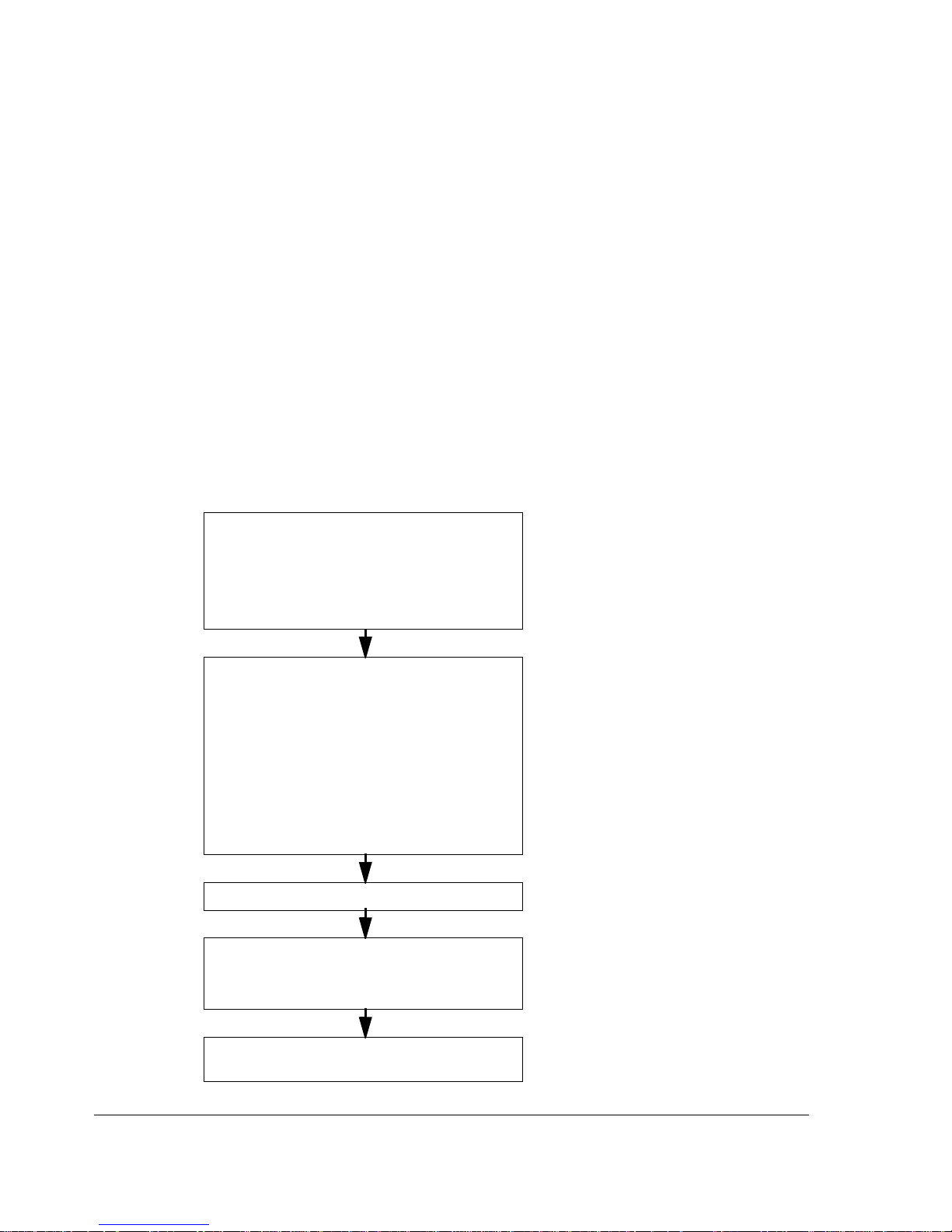
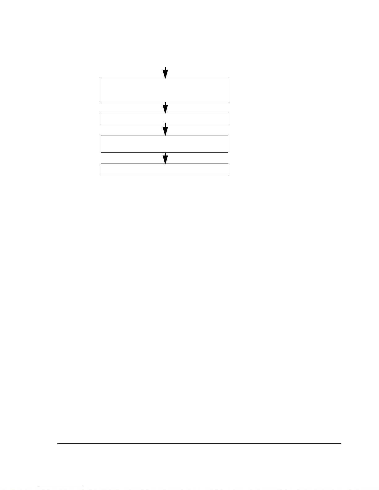
Installation and commissioning flowchart
Task See
Plan the installation.
Check the ambient conditions, ratings, required
cooling air flow, input power connection, compatibility
of the motor, motor connection, and other technical
data.
Select the cables.
Technical data
Planning the electrical installation
Option manuals (if optional equipment is
included)
Unpack and check the units.
Check the type code indicated by the type
designation label with the original order. If the drive is
about to be connected to an IT (ungrounded) system,
check that the drive is not equipped with EMC/RFI
filtering +E202. Check that all necessary optional
modules and equipment are present and correct.
Mechanical installation
Hardware description
For instructions on how to disconnect the EMC/
RFI filtering, contact your local ABB
representative.
If the converter has been non-operational for
more than one year, the converter DC link
capacitors need to be reformed. Contact your
local ABB representative for more information.
Only intact units may be started up.
Check the installation site. Mechanical installation, Technical data
Route the cables. Planning the electrical installation: Routing the
cables
Mount the cabinet line-up. Mechanical installation
Check the insulation of the motor and the motor
cable.
Electrical installation: Checking the insulation of
the assembly
Phone: 800.894.0412 - Fax: 888.723.4773 - Web: www.clrwtr.com - Email: info@clrwtr.com
About this manual
19
Product and service inquiries
Address any inquiries about the product to your local ABB representative, quoting
the type code and serial number of the unit in question. A listing of ABB sales,
support and service contacts can be found by navigating to ABB website and
selecting Drives – Sales, Support and Service network.
Product training
For information on ABB product training, navigate to ABB website and select
Drives – Training courses.
Providing feedback on ABB Drives manuals
Your comments on our manuals are welcome. Go to ABB website and select
Document Library – Manuals feedback form (LV AC drives).
Connect the power cables. Connect the control and
the auxiliary control cables.
Mechanical installation, Planning the electrical
installation, Electrical installation, Resistor
braking (optional)
Check the installation. Installation checklist and start-up
Commission the drive. Installation checklist and start-up and
appropriate firmware manual
Commission the optional brake chopper (if present). Resistor braking
Task See
Phone: 800.894.0412 - Fax: 888.723.4773 - Web: www.clrwtr.com - Email: info@clrwtr.com

About this manual
20
Terms and abbreviations
Term/Abbreviation Explanation
APBU Type of optical branching unit used for connecting parallel-
connected converter modules to the RDCU.
DSSB Diode Supply System Board
DSU Diode Supply Unit
Frame (size) Relates to the construction type of the component in question. For
example, several drive types with different power ratings may have
the same basic construction, and this term is used in reference to all
those drive types.
With the ACS800-07 (> 500 kW), the frame size of the drive
indicates the quantity and frame size of the supply modules, plus the
quantity and frame size of the inverter modules, e.g. “2×D4 + 4×R8i”.
To determine the frame size of a drive type, see the rating tables in
the chapter Technical data.
RDCU Drive control unit.
THD Total Harmonic Distortion
Phone: 800.894.0412 - Fax: 888.723.4773 - Web: www.clrwtr.com - Email: info@clrwtr.com

Hardware description
21
Hardware description
What this chapter contains
This chapter describes the construction of the drive in short.
The ACS800-07
The ACS800-07 is a cabinet-mounted drive for controlling AC motors.
Cabinet line-up
The drive consists of several cubicles that contain the supply and motor terminals,
1 to 4 diode supply module(s), 2 to 6 inverter modules, and optional equipment. The
actual arrangement of the cubicles vary from type to type and the selected options.
See the chapter Dimensions for the different line-up variations.
The picture below shows the main components of a frame 1×D4 + 2×R8i drive.
1
3
4
No. Description
1 Supply (input) cable lead-throughs. Top entry optional.
2 Supply module.
3 Input terminals (behind module). Input cables connect here
if a load switch-disconnector cubicle is not present.
4 Chassis socket for quick supply module connection (behind
module).
5 Supply module switch-disconnector. Not present if the drive
is equipped with an optional load switch-disconnector
cubicle.
6 Supply unit control board (DSSB; mounted sideways).
Contains an actual value display and status LEDs.
7 Inverter DC fuses.
8 Inverter modules.
9 Chassis socket for inverter module output connection
(behind each module).
10 Output terminals (behind each module). Motor cables
connect here if a common motor terminal cubicle is not
present.
11 Motor (output) cable lead-throughs. Not used if optional
common motor terminal cubicle is present.
12 Swing-out frame. Contains the drive control unit with I/O
terminals, and provides space for standard and optional
electrical equipment.
13 Auxiliary voltage transformer (accessible by opening the
swing-out frame).
14 Auxiliary voltage switch with fuses.
8
7
9
10
11
12
13
6
11
10
9
2
5
14
Phone: 800.894.0412 - Fax: 888.723.4773 - Web: www.clrwtr.com - Email: info@clrwtr.com

Hardware description
22
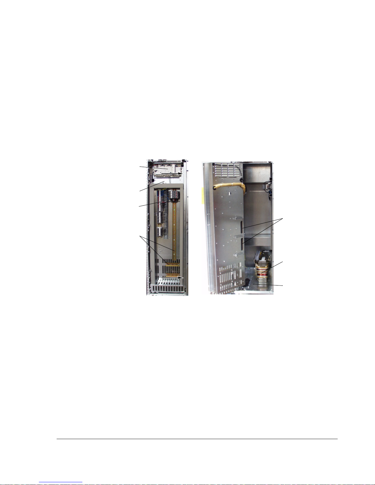
The following drawing represents a 2×D4 + 2×R8i drive with optional load switchdisconnector.
No. Description No. Description
1 Supply (input) cable lead-throughs. Top entry optional. 10 Inverter DC fuses.
2 Input busbars. 11 Inverter modules.
3 Load switch-disconnector. 12 Chassis socket for inverter module output connection
(behind each module).
4 Earthing/Grounding switch (optional). 13 Output terminals (behind each module). Motor cables
connect here if a common motor terminal cubicle is not
present.
5 AC fuses. Only present if the drive is equipped with a
load switch-disconnector or air circuit breaker.
14 Motor (output) cable lead-throughs. Not used if optional
common motor terminal cubicle is present.
6 Supply modules. 15 Swing-out frame. Contains the drive control unit with I/O
terminals, and provides space for standard and optional
electrical equipment.
7 Chassis socket for quick supply module connection
(behind each module).
16 Auxiliary voltage transformer (accessible by opening the
swing-out frame).
8 Supply module switch-disconnectors (coupled to an
operating handle on the cabinet door). Not present if the
drive is equipped with a load switch-disconnector or air
circuit breaker.
17 Auxiliary voltage switch.
9 Supply unit control board (DSSB; mounted sideways).
Contains an actual value display and status LEDs.
1
5
10
9
12
15
16
11
3
4
2
6
77
88
12
13 13
14 14
17
Phone: 800.894.0412 - Fax: 888.723.4773 - Web: www.clrwtr.com - Email: info@clrwtr.com
Hardware description
23
Swing-out frame
The swing-out frame inside the control and I/O cubicle provides space for the control
electronics of the drive, I/O terminal blocks, and optional electrical equipment. The
lead-throughs for I/O cables, the auxiliary voltage transformer, and further space for
additional equipment are available behind the frame. The frame can be opened by
removing the two locking screws (arrowed in the picture below) and moving the
swing-out frame aside. (Depending on selected options, actual equipment of the
drive may differ from what is depicted below.)
Mounting rails for
additional equipment
Remove screws (arrowed) to
release swing-out frame
Drive control unit
(RDCU) with I/O
terminal blocks
Space for optional
terminal block X2
Terminal block X1
Auxiliary voltage
transformer
I/O cable entry (into
swing-out frame)
I/O cable entry (into
cabinet)
Phone: 800.894.0412 - Fax: 888.723.4773 - Web: www.clrwtr.com - Email: info@clrwtr.com
Hardware description
24
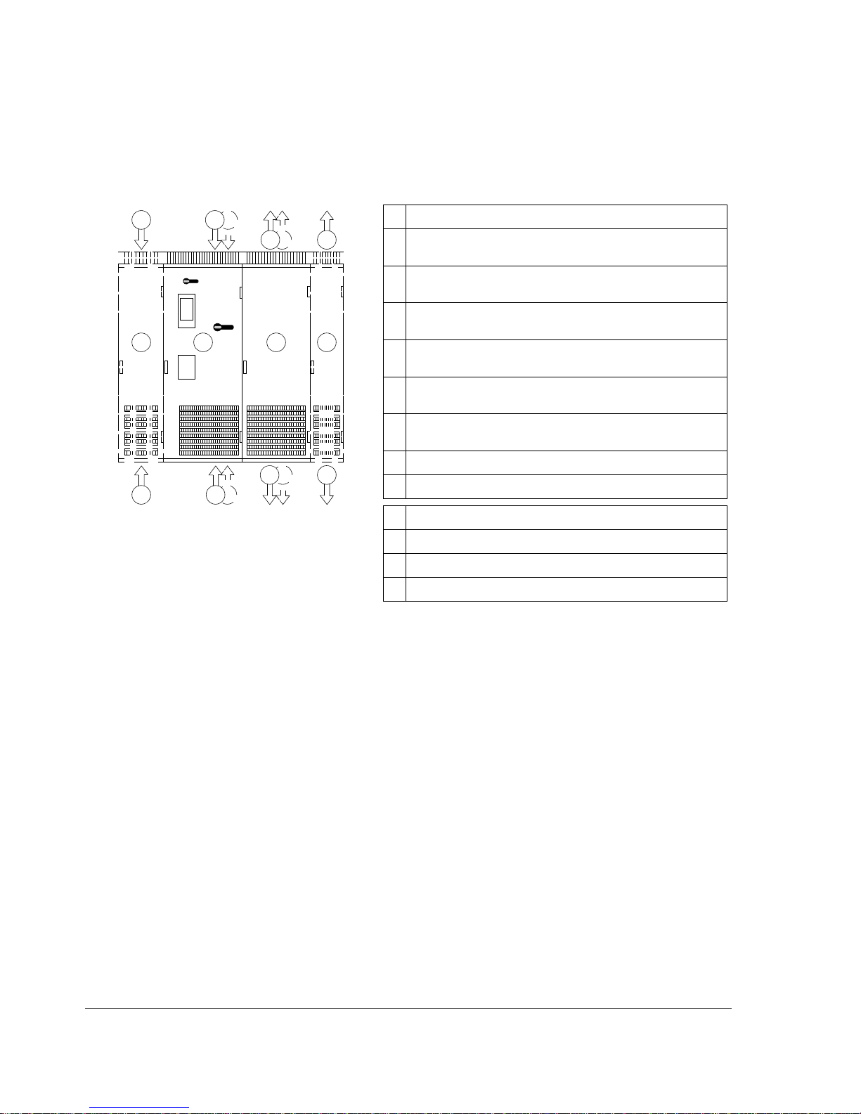
Cabling direction
The drawing below shows the available power cabling directions of the drive. Note
that the desired cabling direction must be specified on ordering.
3
2
A B C D
Description
1 Main supply – Bottom entry at each supply module (without load
switch-disconnector or air breaker)
2 Main supply – Bottom entry with load switch-disconnector or air
circuit breaker
3 Main supply – Top entry at each supply module (without load
switch-disconnector or air circuit breaker) (not for IP54)
4 Main supply – Top entry with load switch-disconnector or air
circuit breaker
5 Motor output – Bottom exit at each inverter module (without
common motor terminal cubicle)
6 Motor output – Top exit at each inverter module (without common
motor terminal cubicle). Added depth: 130 mm
7 Motor output – Bottom exit with common motor terminal cubicle
8 Motor output – Top exit with common motor terminal cubicle
A Load switch-disconnector or air circuit breaker cubicle (optional)
B Control, I/O and supply cubicle
C Inverter unit cubicle
D Common motor terminal cubicle (optional)
11
4 3
55
66
7
8
Phone: 800.894.0412 - Fax: 888.723.4773 - Web: www.clrwtr.com - Email: info@clrwtr.com
 Loading...