


 Loading...
ACS 160 Installation and
Start-up Guide
RS485 and RS232
Adapter Module CFB-RS
RS485 and RS232
Adapter Module CFB-RS
Installation and
Start-up Guide
3BFE 64390431 R0125 EN EFFECTIVE: 23.3.2001

Safety Instructions
Overview
This chapter states the safety instructions that must be followed when installing and operating the RS485/RS232 adapter. If neglected, physical injury and death may follow, or damage may occur to the frequency converter, the motor and driven equipment. The material in this chapter must be studied before attempting any work on, or with, the unit.
Warnings
Warnings are used to inform of conditions which can, if proper steps are not taken, lead to a serious fault condition, physical injury and death.
Readers are informed of situations that can result in serious physical injury and/or serious damage to equipment with the following symbols:
Dangerous Voltage Warning: warns of situations in which a high voltage can cause physical injury and/or damage equipment. The text next to this symbol describes ways to avoid the danger.
General Warning: warns of situations which can cause physical injury and/or damage equipment by means other than electrical. The text next to this symbol describes ways to avoid the danger.
RS485 and RS232 Adapter Installation and Start-up Guide |
i |

Safety Instructions
ii |
RS485 and RS232 Adapter Installation and Start-up Guide |

Table of Contents
Safety Instructions |
|
Overview ...................................................................................................... |
i |
Warnings ...................................................................................................... |
i |
Chapter 1 –Introduction |
|
Overview .................................................................................................. |
1-1 |
Delivery Check ......................................................................................... |
1-1 |
How to Use This Guide ............................................................................ |
1-1 |
Chapter 2 – Installation |
|
Mounting .................................................................................................. |
2-2 |
Connectors and Switches ........................................................................ |
2-3 |
Selecting the Communication Speed ....................................................... |
2-4 |
Selecting RS485 or RS232 Mode ............................................................ |
2-5 |
RS485 Bus Termination ........................................................................... |
2-5 |
Installation to RS485 Bus......................................................................... |
2-6 |
Installation to RS232 Bus......................................................................... |
2-8 |
Earthing and Termination ....................................................................... |
2-11 |
Chapter 3 – Programming |
|
General .................................................................................................... |
3-1 |
Communication Settings .......................................................................... |
3-2 |
Control Locations ..................................................................................... |
3-5 |
Diagnostic Counters................................................................................. |
3-6 |
Chapter 4 – Communication |
|
Introduction to Modbus............................................................................. |
4-1 |
Register Read and Write .......................................................................... |
4-1 |
Register Mapping ..................................................................................... |
4-2 |
Exception Codes ...................................................................................... |
4-3 |
Function Codes ........................................................................................ |
4-4 |
The Control Word and the Status Word ................................................... |
4-4 |
RS485 and RS232 Adapter Installation and Start-up Guide |
iii |

References............................................................................................... |
4-8 |
Actual Values ......................................................................................... |
4-11 |
Fault and Alarm Status .......................................................................... |
4-13 |
Chapter 5 – Fault Tracing |
|
Appendix A – Parameter Scaling |
|
Effect of Resolution.................................................................................. |
A-1 |
Signed Values.......................................................................................... |
A-1 |
Appendix B– Technical Data |
|
RS-485 Link ............................................................................................. |
B-1 |
CFB-RS.................................................................................................... |
B-1 |
Appendix C– Ambient Conditions |
|
Operation ................................................................................................ |
C-1 |
Storage and Transportation .................................................................... |
C-1 |
iv |
RS485 and RS232 Adapter Installation and Start-up Guide |

Chapter 1 –Introduction
Overview
The RS485 and RS232 adapter is used for connecting the ACS 160 frequency converter to a serial Modbus (RS232 or RS485) network. The adapter is IP65 protected for use in demanding environmental conditions.
Delivery Check
The option package includes:
•RS485/RS232 Adapter
•Installation and Start-up Guide for RS485 and RS232 Adapter
•Two M16 x 1,5 cable glands with O-ring.
•Two M4 x 12 mounting screws
How to Use This Guide
The purpose of this Guide is to provide the information necessary to install, commission, use, and to fault diagnose the adapter.
Safety Instructions describe the formats for warnings and notations used within this guide. This chapter also states the safety instructions which apply to the installation and operation of the RS485/RS232 Adapter.
Chapter 1 – Introduction, the chapter you are reading now, contains a short description of this manual and a list of related publications.
Chapter 2 – Installation contains instructions for mechanical and electrical installation of the adapter.
Chapter 3 – Programming explains how to program the ACS 160 drive for Modbus communication.
Chapter 4 – Communication describes the Modbus communication on ACS 160 drives.
Chapter 5 – Fault Tracing describes how to diagnose the most common problems with the adapter.
RS485 and RS232 Adapter Installation and Start-up Guide |
1-1 |

Chapter 1 –Introduction
Appendix A– Parameter Scaling describes the scaling when parameters are accessed through the Modbus network.
Appendix B– Technical data of the module.
Appendix C– Ambient conditions.
Conventions Used in This Guide
This manual uses some terms and conventions which might not be known to every user of this manual. Some of these terms are described below.
4XXXX Register Area
Modicon PLCs have a signed integer data table area, which is used for Analogue Output modules and for storing temporary or set-point values. These registers are in the address area starting from 40001. The last register address available on PLCs depends on the available memory, but is less than 49999.
The ACS 160 drive simulates this area by providing a read and write access to its parameters through this register address area.
Related Publications
ACS 160 User’s Manual.
1-2 |
RS485 and RS232 Adapter Installation and Start-up Guide |

Chapter 2 – Installation
This chapter contains instructions for setting up the RS485/RS232 adapter.
WARNING! Verify that the ACS 160 is not powered before starting the installation. Follow the safety instructions given in this Guide and in the ACS 160 User’s Manual.
Drive connection Cable
Base |
Mounting Screws |
|
(2 pcs) |
||
|
Cover Screws (4 pcs)
Circuit Board |
Cover |
|
Assembly |
||
|
Cable Glands
for Bus Cables (2 pcs)
Figure 2-1 Exploded view of the CFB-RS Adapter Module
RS485 and RS232 Adapter Installation and Start-up Guide |
2-1 |

Chapter 2 – Installation
Mounting
The CFB-RS can be mounted onto the ACS 160 drive with two screws as shown in the ACS 160 User's Manual. This also provides the earthing of the module housing.
The CFB-RS uses the control panel connector of the drive. The CFB-RS is powered through this connector.
The CFB-RS provides two cable entries for the incoming and outgoing bus cables. The cables are connected to a detachable terminal header.
If only one bus cable is connected, the unused cable entry should be plugged.
Remove the front cover to access the configuration switches and jumpers.
2-2 |
RS485 and RS232 Adapter Installation and Start-up Guide |
Chapter 2 – Installation
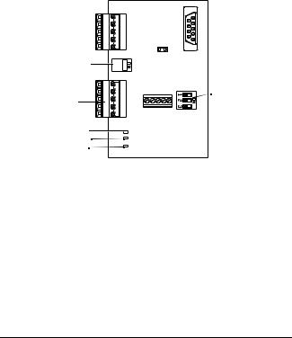
Connectors and Switches
The adapter operates either in RS232 mode or RS485 mode. The mode can be selected with a jumper. By default, the adapter operates in RS485 mode at a communication speed of 9600 bps (bits per second).
RS485 terminal X1
5 4 3 2 1
RS485 bus termination switch S1
|
1 |
RS485 terminal X2 |
2 |
3 |
|
LEDs: |
5 4 |
|
TxD
RxD
Power
RS232 terminal X4

 RS323/RS485 mode selection jumper S3
Communication speed setting
DIP switch S2
Figure 2-2 Connectors and switches.
RS485 and RS232 Adapter Installation and Start-up Guide |
2-3 |
Chapter 2 – Installation
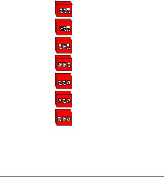
Selecting the Communication Speed
Communication speed is selected by DIP switch S2 and by parameter 5201 COMM SPEED. The factory setting for the communication speed is 9600 bps (bits per second).
Communication speed setting using DIP switch S2 is needed only when the adapter operates in RS485 mode.
DIP switch S2 Communication speed
ON |
300 bps |
1 2 3 |
|
ON |
600 bps |
|
|
1 2 3 |
|
ON |
1200 bps |
1 2 3 |
|
ON |
2400 bps |
|
|
1 2 3 |
|
|
4800 bps |
ON |
1 2 3 |
ON |
9600 bps |
1 2 3 |
|
|
19200 bps |
|
ON |
||
|
1 2 3 |
Figure 2-3 Selecting the communication speed for the adapter.
2-4 |
RS485 and RS232 Adapter Installation and Start-up Guide |

Chapter 2 – Installation
Selecting RS485 or RS232 Mode
The adapter operates either in RS232 mode or in RS485 mode, selectable by a jumper. As a factory setting, the adapter operates in RS485 mode.
 S3
S3
Jumper S3 Mode
RS485
1
RS232
2
Figure 2-4 Selecting the operating mode.
RS485 Bus Termination
The RS485 bus must be terminated using 120 9 resistors at both ends of the network. The adapter has built-in termination resistors that can be enabled by the bus termination switch S1. Refer to 'Earthing and Termination' on page 2- 11. By default, bus termination is enabled (ON).
Bus termination switch |
S1 |
Figure 2-5 Selecting RS485 termination impedance.
RS485 and RS232 Adapter Installation and Start-up Guide |
2-5 |
Chapter 2 – Installation
Installation to RS485 Bus
1Make sure power is not connected to the ACS 160.
2Set the adapter switches:
•Confirm that the operation mode is RS485 (jumper S3)
•Set communication speed of the adapter with DIP switch S2
•If the termination is not needed, use switch S1 to disable it.
3Mount the adapter on the side of the ACS 160. Leave the drive connection cable disconnected.
4Wire the adapter to the RS485 network (X1 and X2).
5Connect the control panel to the drive.
6Connect power to ACS 160.
7Set up communication: Station number, communication speed of the drive and parity. Refer to Chapter 3 – Programming.
8Set up other drive parameters as needed. Refer to ACS 160 User’s Manual and Chapter 3 of this manual.
9Disconnect power from the ACS 160.
10Disconnect control panel and connect drive connection cable of the adapter.
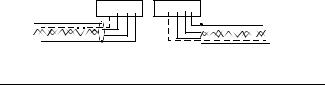
Wiring
The RS485 link is a daisy-chained bus, without dropout lines. The RS485 link should also be terminated on both physical ends of the wire to reduce the noise on the network.
Modbus network should be wired using Belden 9841 or equivalent. Belden 9841 is a single twisted shielded pair cable with a wave impedance of 120 9.
The network should be connected according to Figure 2-6 below.
1 2 3 4 5 |
1 2 3 4 5 |
Figure 2-6 RS485 wiring.
2-6 |
RS485 and RS232 Adapter Installation and Start-up Guide |
Chapter 2 – Installation
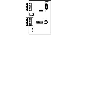
Table 2-1 RS485 connection terminals. Terminals X1 and X2 are connected in parallel.
|
X1, X2 |
Description |
|
1 |
|
- |
No connection |
|
|
|
|
2 |
|
C |
Common. Connected to ACS 160 |
|
|
|
chassis through 100 9 impedance |
|
|
|
|
3 |
|
A |
Data negative |
4 |
|
B |
Data positive |
5 |
|
Shield |
Cable shield |
RS485 terminal X1
RS485 terminal X2
Figure 2-7 RS485 connection terminals X1 and X2.
RS485 and RS232 Adapter Installation and Start-up Guide |
2-7 |
Loading...