


 Loading...
—
ABB MACHINERY DRIVES
ACS380 machinery control program
Firmware manual

—
List of related manuals
Drive hardware manuals and guides |
Code (English) |
Drive/converter/inverter safety instructions |
3AXD50000037978 |
ACS380 Hardware manual |
3AXD50000029274 |
Drive firmware manuals and guides |
|
ACS380 Firmware manual |
3AXD50000029275 |
ACS380 Quick installation and start-up guide |
3AXD50000018553 |
ACS380 User interface guide |
3AXD50000022224 |
Option manuals and guides |
|
ACS-AP-x Assistant control panels user’s manual |
3AUA0000085685 |
ACS-BP-S Basic control panel user’s manual |
3AXD50000032527 |
FCAN-01 CANopen adapter module user’s manual |
3AFE68615500 |
FECA-01 EtherCAT adapter module user’s manual |
3AUA0000068940 |
FENA-01/-11/-21 Ethernet adapter module user’s |
3AUA0000093568 |
manual |
|
FPBA-01 PROFIBUS DP adapter module user’s manual |
3AFE68573271 |
FEPL-02 Ethernet POWERLINK adapter module user’s |
3AUA0000123527 |
manual |
|
Tool and maintenance manuals and guides |
|
Drive composer PC tool user’s manual |
3AUA0000094606 |
Converter module capacitor reforming instructions |
38FE64059629 |
Adaptive Programming Application guide |
3AXD50000028574 |
NETA-21 remote monitoring tool user’s manual |
3AUA0000096939 |
NETA-21 remote monitoring tool installation and start- |
3AUA0000096881 |
up guide |
|
You can find manuals and other product documents in PDF format on the Internet. See section Document library on the Internet on the inside of the back cover. For manuals not available in the Document library, contact your local ABB representative.
The code below opens an online listing of the manuals applicable to the product:

Firmware manual
ACS380 machinery control program
Table of contents
3. Start-up, ID run and use
2018 ABB Oy. All Rights Reserved. |
3AXD50000029275 Rev E |
|
EN |
|
EFFECTIVE: 2018-05-05 |

Table of contents 5
Table of contents
1. Introduction to the manual
Contents . . . . . . . . . . . . . . . . . . . . . . . . . . . . . . . . . . . . . . . . . . . . . . . . . . . . . . . . . . . . . . . . . 11 Applicability . . . . . . . . . . . . . . . . . . . . . . . . . . . . . . . . . . . . . . . . . . . . . . . . . . . . . . . . . . . . . . . 11 Safety instructions . . . . . . . . . . . . . . . . . . . . . . . . . . . . . . . . . . . . . . . . . . . . . . . . . . . . . . . . . . 11 Target audience . . . . . . . . . . . . . . . . . . . . . . . . . . . . . . . . . . . . . . . . . . . . . . . . . . . . . . . . . . . . 12 Purpose of the manual . . . . . . . . . . . . . . . . . . . . . . . . . . . . . . . . . . . . . . . . . . . . . . . . . . . . . . 12 Contents of the manual . . . . . . . . . . . . . . . . . . . . . . . . . . . . . . . . . . . . . . . . . . . . . . . . . . . . . . 12 Terms and abbreviations . . . . . . . . . . . . . . . . . . . . . . . . . . . . . . . . . . . . . . . . . . . . . . . . . . . . . 13 Related manuals . . . . . . . . . . . . . . . . . . . . . . . . . . . . . . . . . . . . . . . . . . . . . . . . . . . . . . . . . . . 15 Cybersecurity disclaimer . . . . . . . . . . . . . . . . . . . . . . . . . . . . . . . . . . . . . . . . . . . . . . . . . . . . . 15
2. Control panel
Contents . . . . . . . . . . . . . . . . . . . . . . . . . . . . . . . . . . . . . . . . . . . . . . . . . . . . . . . . . . . . . . . . . 17 Control panel . . . . . . . . . . . . . . . . . . . . . . . . . . . . . . . . . . . . . . . . . . . . . . . . . . . . . . . . . . . . . . 17 Home view and Message view . . . . . . . . . . . . . . . . . . . . . . . . . . . . . . . . . . . . . . . . . . . . . . . . 18 Options menu and Main menu . . . . . . . . . . . . . . . . . . . . . . . . . . . . . . . . . . . . . . . . . . . . . . . . 19 Options menu . . . . . . . . . . . . . . . . . . . . . . . . . . . . . . . . . . . . . . . . . . . . . . . . . . . . . . . . . . 19 Main menu . . . . . . . . . . . . . . . . . . . . . . . . . . . . . . . . . . . . . . . . . . . . . . . . . . . . . . . . . . . . 19
3. Start-up, ID run and use
Contents . . . . . . . . . . . . . . . . . . . . . . . . . . . . . . . . . . . . . . . . . . . . . . . . . . . . . . . . . . . . . . . . . 23 Start up the drive . . . . . . . . . . . . . . . . . . . . . . . . . . . . . . . . . . . . . . . . . . . . . . . . . . . . . . . . . . . 23 Do the identification (ID) run . . . . . . . . . . . . . . . . . . . . . . . . . . . . . . . . . . . . . . . . . . . . . . . . . . 25 Background information . . . . . . . . . . . . . . . . . . . . . . . . . . . . . . . . . . . . . . . . . . . . . . . . . . 25 ID run steps . . . . . . . . . . . . . . . . . . . . . . . . . . . . . . . . . . . . . . . . . . . . . . . . . . . . . . . . . . . . 25
Start and stop the drive . . . . . . . . . . . . . . . . . . . . . . . . . . . . . . . . . . . . . . . . . . . . . . . . . . . . . . 27 Change the rotation direction . . . . . . . . . . . . . . . . . . . . . . . . . . . . . . . . . . . . . . . . . . . . . . . . . 27 Set the speed or frequency reference . . . . . . . . . . . . . . . . . . . . . . . . . . . . . . . . . . . . . . . . . . . 27 Set the drive parameters . . . . . . . . . . . . . . . . . . . . . . . . . . . . . . . . . . . . . . . . . . . . . . . . . . . . . 28 Open Diagnostics . . . . . . . . . . . . . . . . . . . . . . . . . . . . . . . . . . . . . . . . . . . . . . . . . . . . . . . . . . 28 Change the units . . . . . . . . . . . . . . . . . . . . . . . . . . . . . . . . . . . . . . . . . . . . . . . . . . . . . . . . . . . 29
4. Control macros
Contents . . . . . . . . . . . . . . . . . . . . . . . . . . . . . . . . . . . . . . . . . . . . . . . . . . . . . . . . . . . . . . . . . 31 ABB standard macro . . . . . . . . . . . . . . . . . . . . . . . . . . . . . . . . . . . . . . . . . . . . . . . . . . . . . . . . 32 Default control connections for the ABB standard macro . . . . . . . . . . . . . . . . . . . . . . . . . 33 ABB limited macro . . . . . . . . . . . . . . . . . . . . . . . . . . . . . . . . . . . . . . . . . . . . . . . . . . . . . . . . . . 35 Default control connections for the ABB limited macro . . . . . . . . . . . . . . . . . . . . . . . . . . . 35 Fieldbus control macro . . . . . . . . . . . . . . . . . . . . . . . . . . . . . . . . . . . . . . . . . . . . . . . . . . . . . . 36 Default control connections for the Fieldbus macro . . . . . . . . . . . . . . . . . . . . . . . . . . . . . 36 Alternate macro . . . . . . . . . . . . . . . . . . . . . . . . . . . . . . . . . . . . . . . . . . . . . . . . . . . . . . . . . . . . 38 Default control connections for the Alternate macro . . . . . . . . . . . . . . . . . . . . . . . . . . . . . 39

6 Table of contents
Motor potentiometer macro . . . . . . . . . . . . . . . . . . . . . . . . . . . . . . . . . . . . . . . . . . . . . . . . . . 41 Default control connections for the Motor potentiometer macro . . . . . . . . . . . . . . . . . . . 42 PID control macro . . . . . . . . . . . . . . . . . . . . . . . . . . . . . . . . . . . . . . . . . . . . . . . . . . . . . . . . . . 44 Default control connections for PID control macro . . . . . . . . . . . . . . . . . . . . . . . . . . . . . . 44 Modbus macro . . . . . . . . . . . . . . . . . . . . . . . . . . . . . . . . . . . . . . . . . . . . . . . . . . . . . . . . . . . . 46 Default control connections for the Modbus macro . . . . . . . . . . . . . . . . . . . . . . . . . . . . . 47 Parameter default values for different macros . . . . . . . . . . . . . . . . . . . . . . . . . . . . . . . . . . . . 49
5. Program features |
|
Contents . . . . . . . . . . . . . . . . . . . . . . . . . . . . . . . . . . . . . . . . . . . . . . . . . . . . . . . . . . . . . . . . . |
51 |
Local and external control locations . . . . . . . . . . . . . . . . . . . . . . . . . . . . . . . . . . . . . . . . . . . . |
52 |
Local control . . . . . . . . . . . . . . . . . . . . . . . . . . . . . . . . . . . . . . . . . . . . . . . . . . . . . . . . . . . |
52 |
External control . . . . . . . . . . . . . . . . . . . . . . . . . . . . . . . . . . . . . . . . . . . . . . . . . . . . . . . . |
53 |
Operating modes and motor control modes . . . . . . . . . . . . . . . . . . . . . . . . . . . . . . . . . . . . . . |
54 |
Overview diagram of control hierarchy . . . . . . . . . . . . . . . . . . . . . . . . . . . . . . . . . . . . . . . |
54 |
Speed control mode . . . . . . . . . . . . . . . . . . . . . . . . . . . . . . . . . . . . . . . . . . . . . . . . . . . . . |
56 |
Torque control mode . . . . . . . . . . . . . . . . . . . . . . . . . . . . . . . . . . . . . . . . . . . . . . . . . . . . |
56 |
Frequency control mode . . . . . . . . . . . . . . . . . . . . . . . . . . . . . . . . . . . . . . . . . . . . . . . . . |
56 |
Special control modes . . . . . . . . . . . . . . . . . . . . . . . . . . . . . . . . . . . . . . . . . . . . . . . . . . . |
56 |
Settings . . . . . . . . . . . . . . . . . . . . . . . . . . . . . . . . . . . . . . . . . . . . . . . . . . . . . . . . . . . . . . |
57 |
Autophasing . . . . . . . . . . . . . . . . . . . . . . . . . . . . . . . . . . . . . . . . . . . . . . . . . . . . . . . . . . . |
57 |
Drive configuration and programming . . . . . . . . . . . . . . . . . . . . . . . . . . . . . . . . . . . . . . . . . . |
60 |
Programming via parameters . . . . . . . . . . . . . . . . . . . . . . . . . . . . . . . . . . . . . . . . . . . . . . |
60 |
Adaptive programming . . . . . . . . . . . . . . . . . . . . . . . . . . . . . . . . . . . . . . . . . . . . . . . . . . . |
61 |
Control interfaces . . . . . . . . . . . . . . . . . . . . . . . . . . . . . . . . . . . . . . . . . . . . . . . . . . . . . . . . . . |
64 |
Programmable analog inputs . . . . . . . . . . . . . . . . . . . . . . . . . . . . . . . . . . . . . . . . . . . . . . |
64 |
Programmable analog outputs . . . . . . . . . . . . . . . . . . . . . . . . . . . . . . . . . . . . . . . . . . . . . |
64 |
Programmable digital inputs and outputs . . . . . . . . . . . . . . . . . . . . . . . . . . . . . . . . . . . . . |
64 |
Programmable relay outputs . . . . . . . . . . . . . . . . . . . . . . . . . . . . . . . . . . . . . . . . . . . . . . |
65 |
Programmable I/O extensions . . . . . . . . . . . . . . . . . . . . . . . . . . . . . . . . . . . . . . . . . . . . . |
65 |
Fieldbus control . . . . . . . . . . . . . . . . . . . . . . . . . . . . . . . . . . . . . . . . . . . . . . . . . . . . . . . . |
65 |
Motor control . . . . . . . . . . . . . . . . . . . . . . . . . . . . . . . . . . . . . . . . . . . . . . . . . . . . . . . . . . . . . |
66 |
Motor types . . . . . . . . . . . . . . . . . . . . . . . . . . . . . . . . . . . . . . . . . . . . . . . . . . . . . . . . . . . |
66 |
Motor identification . . . . . . . . . . . . . . . . . . . . . . . . . . . . . . . . . . . . . . . . . . . . . . . . . . . . . . |
66 |
Power loss ride-through . . . . . . . . . . . . . . . . . . . . . . . . . . . . . . . . . . . . . . . . . . . . . . . . . . |
66 |
Vector control . . . . . . . . . . . . . . . . . . . . . . . . . . . . . . . . . . . . . . . . . . . . . . . . . . . . . . . . . . |
66 |
Reference ramping . . . . . . . . . . . . . . . . . . . . . . . . . . . . . . . . . . . . . . . . . . . . . . . . . . . . . . |
67 |
Constant speeds/frequencies . . . . . . . . . . . . . . . . . . . . . . . . . . . . . . . . . . . . . . . . . . . . . . |
68 |
Critical speeds/frequencies . . . . . . . . . . . . . . . . . . . . . . . . . . . . . . . . . . . . . . . . . . . . . . . |
68 |
Rush control . . . . . . . . . . . . . . . . . . . . . . . . . . . . . . . . . . . . . . . . . . . . . . . . . . . . . . . . . . . |
70 |
Encoder echo support . . . . . . . . . . . . . . . . . . . . . . . . . . . . . . . . . . . . . . . . . . . . . . . . . . . |
70 |
Jogging . . . . . . . . . . . . . . . . . . . . . . . . . . . . . . . . . . . . . . . . . . . . . . . . . . . . . . . . . . . . . . |
70 |
Speed control performance figures . . . . . . . . . . . . . . . . . . . . . . . . . . . . . . . . . . . . . . . . . |
73 |
Torque control performance figures . . . . . . . . . . . . . . . . . . . . . . . . . . . . . . . . . . . . . . . . . |
73 |
Scalar motor control . . . . . . . . . . . . . . . . . . . . . . . . . . . . . . . . . . . . . . . . . . . . . . . . . . . . . |
74 |
User load curve . . . . . . . . . . . . . . . . . . . . . . . . . . . . . . . . . . . . . . . . . . . . . . . . . . . . . . . . |
75 |
U/f ratio . . . . . . . . . . . . . . . . . . . . . . . . . . . . . . . . . . . . . . . . . . . . . . . . . . . . . . . . . . . . . . . |
76 |
Flux braking . . . . . . . . . . . . . . . . . . . . . . . . . . . . . . . . . . . . . . . . . . . . . . . . . . . . . . . . . . . |
76 |
DC magnetization . . . . . . . . . . . . . . . . . . . . . . . . . . . . . . . . . . . . . . . . . . . . . . . . . . . . . . . |
77 |
Energy optimization . . . . . . . . . . . . . . . . . . . . . . . . . . . . . . . . . . . . . . . . . . . . . . . . . . . . . |
79 |

Table of contents |
7 |
Switching frequency . . . . . . . . . . . . . . . . . . . . . . . . . . . . . . . . . . . . . . . . . . . . . . . . . . . . |
. 79 |
Speed compensated stop . . . . . . . . . . . . . . . . . . . . . . . . . . . . . . . . . . . . . . . . . . . . . . . . . |
80 |
Application control . . . . . . . . . . . . . . . . . . . . . . . . . . . . . . . . . . . . . . . . . . . . . . . . . . . . . . . . . . |
81 |
Control macros . . . . . . . . . . . . . . . . . . . . . . . . . . . . . . . . . . . . . . . . . . . . . . . . . . . . . . . . . |
81 |
Process PID control . . . . . . . . . . . . . . . . . . . . . . . . . . . . . . . . . . . . . . . . . . . . . . . . . . . . . |
81 |
Mechanical brake control . . . . . . . . . . . . . . . . . . . . . . . . . . . . . . . . . . . . . . . . . . . . . . . . . |
84 |
DC voltage control . . . . . . . . . . . . . . . . . . . . . . . . . . . . . . . . . . . . . . . . . . . . . . . . . . . . . . . . . . |
90 |
Overvoltage control . . . . . . . . . . . . . . . . . . . . . . . . . . . . . . . . . . . . . . . . . . . . . . . . . . . . . . |
90 |
Undervoltage control (power loss ride-through) . . . . . . . . . . . . . . . . . . . . . . . . . . . . . . . . |
90 |
Voltage control and trip limits . . . . . . . . . . . . . . . . . . . . . . . . . . . . . . . . . . . . . . . . . . . . . . |
91 |
Settings . . . . . . . . . . . . . . . . . . . . . . . . . . . . . . . . . . . . . . . . . . . . . . . . . . . . . . . . . . . . . . . |
92 |
Brake chopper . . . . . . . . . . . . . . . . . . . . . . . . . . . . . . . . . . . . . . . . . . . . . . . . . . . . . . . . . . |
93 |
Limit to limit control . . . . . . . . . . . . . . . . . . . . . . . . . . . . . . . . . . . . . . . . . . . . . . . . . . . . . . . . . |
94 |
Limit to limit control function . . . . . . . . . . . . . . . . . . . . . . . . . . . . . . . . . . . . . . . . . . . . . . . |
95 |
Limitations . . . . . . . . . . . . . . . . . . . . . . . . . . . . . . . . . . . . . . . . . . . . . . . . . . . . . . . . . . . . . |
95 |
Tips . . . . . . . . . . . . . . . . . . . . . . . . . . . . . . . . . . . . . . . . . . . . . . . . . . . . . . . . . . . . . . . . . . |
96 |
Safety and protections . . . . . . . . . . . . . . . . . . . . . . . . . . . . . . . . . . . . . . . . . . . . . . . . . . . . . . . |
97 |
Fixed/Standard protections . . . . . . . . . . . . . . . . . . . . . . . . . . . . . . . . . . . . . . . . . . . . . . . . |
97 |
Emergency stop . . . . . . . . . . . . . . . . . . . . . . . . . . . . . . . . . . . . . . . . . . . . . . . . . . . . . . . . |
97 |
Motor thermal protection . . . . . . . . . . . . . . . . . . . . . . . . . . . . . . . . . . . . . . . . . . . . . . . . . . |
98 |
Programmable protection functions . . . . . . . . . . . . . . . . . . . . . . . . . . . . . . . . . . . . . . . . |
101 |
Automatic fault resets . . . . . . . . . . . . . . . . . . . . . . . . . . . . . . . . . . . . . . . . . . . . . . . . . . . |
103 |
Diagnostics . . . . . . . . . . . . . . . . . . . . . . . . . . . . . . . . . . . . . . . . . . . . . . . . . . . . . . . . . . . . . . |
104 |
Signal supervision . . . . . . . . . . . . . . . . . . . . . . . . . . . . . . . . . . . . . . . . . . . . . . . . . . . . . . |
104 |
Energy saving calculators . . . . . . . . . . . . . . . . . . . . . . . . . . . . . . . . . . . . . . . . . . . . . . . . |
104 |
Load analyzer . . . . . . . . . . . . . . . . . . . . . . . . . . . . . . . . . . . . . . . . . . . . . . . . . . . . . . . . . |
104 |
Miscellaneous . . . . . . . . . . . . . . . . . . . . . . . . . . . . . . . . . . . . . . . . . . . . . . . . . . . . . . . . . . . . |
106 |
Backup and restore . . . . . . . . . . . . . . . . . . . . . . . . . . . . . . . . . . . . . . . . . . . . . . . . . . . . . |
106 |
User parameter sets . . . . . . . . . . . . . . . . . . . . . . . . . . . . . . . . . . . . . . . . . . . . . . . . . . . . |
106 |
Data storage parameters . . . . . . . . . . . . . . . . . . . . . . . . . . . . . . . . . . . . . . . . . . . . . . . . |
107 |
Parameter checksum calculation . . . . . . . . . . . . . . . . . . . . . . . . . . . . . . . . . . . . . . . . . . |
107 |
Motor potentiometer . . . . . . . . . . . . . . . . . . . . . . . . . . . . . . . . . . . . . . . . . . . . . . . . . . . . |
108 |
User lock . . . . . . . . . . . . . . . . . . . . . . . . . . . . . . . . . . . . . . . . . . . . . . . . . . . . . . . . . . . . . |
109 |
6. Parameters |
|
Contents . . . . . . . . . . . . . . . . . . . . . . . . . . . . . . . . . . . . . . . . . . . . . . . . . . . . . . . . . . . . . . . . |
111 |
Terms and abbreviations . . . . . . . . . . . . . . . . . . . . . . . . . . . . . . . . . . . . . . . . . . . . . . . . . . . . |
112 |
Fieldbus addresses . . . . . . . . . . . . . . . . . . . . . . . . . . . . . . . . . . . . . . . . . . . . . . . . . . . . . . . . |
112 |
Summary of parameter groups . . . . . . . . . . . . . . . . . . . . . . . . . . . . . . . . . . . . . . . . . . . . . . . |
113 |
Parameter listing . . . . . . . . . . . . . . . . . . . . . . . . . . . . . . . . . . . . . . . . . . . . . . . . . . . . . . . . . . |
115 |
01 Actual values . . . . . . . . . . . . . . . . . . . . . . . . . . . . . . . . . . . . . . . . . . . . . . . . . . . . . . . |
115 |
03 Input references . . . . . . . . . . . . . . . . . . . . . . . . . . . . . . . . . . . . . . . . . . . . . . . . . . . . . |
118 |
04 Warnings and faults . . . . . . . . . . . . . . . . . . . . . . . . . . . . . . . . . . . . . . . . . . . . . . . . . . |
119 |
05 Diagnostics . . . . . . . . . . . . . . . . . . . . . . . . . . . . . . . . . . . . . . . . . . . . . . . . . . . . . . . . . |
120 |
06 Control and status words . . . . . . . . . . . . . . . . . . . . . . . . . . . . . . . . . . . . . . . . . . . . . . |
123 |
07 System info . . . . . . . . . . . . . . . . . . . . . . . . . . . . . . . . . . . . . . . . . . . . . . . . . . . . . . . . |
128 |
09 Crane application signals . . . . . . . . . . . . . . . . . . . . . . . . . . . . . . . . . . . . . . . . . . . . . . |
130 |
10 Standard DI, RO . . . . . . . . . . . . . . . . . . . . . . . . . . . . . . . . . . . . . . . . . . . . . . . . . . . . . |
131 |
11 Standard DIO, FI, FO . . . . . . . . . . . . . . . . . . . . . . . . . . . . . . . . . . . . . . . . . . . . . . . . . |
135 |
12 Standard AI . . . . . . . . . . . . . . . . . . . . . . . . . . . . . . . . . . . . . . . . . . . . . . . . . . . . . . . . |
141 |

8 Table of contents |
|
|
13 |
Standard AO . . . . . . . . . . . . . . . . . . . . . . . . . . . . . . . . . . . . . . . . . . . . . . . . . . . . . . . |
146 |
15 |
I/O extension module . . . . . . . . . . . . . . . . . . . . . . . . . . . . . . . . . . . . . . . . . . . . . . . . |
149 |
19 |
Operation mode . . . . . . . . . . . . . . . . . . . . . . . . . . . . . . . . . . . . . . . . . . . . . . . . . . . . |
153 |
20 |
Start/stop/direction . . . . . . . . . . . . . . . . . . . . . . . . . . . . . . . . . . . . . . . . . . . . . . . . . . |
155 |
21 |
Start/stop mode . . . . . . . . . . . . . . . . . . . . . . . . . . . . . . . . . . . . . . . . . . . . . . . . . . . . . |
169 |
22 |
Speed reference selection . . . . . . . . . . . . . . . . . . . . . . . . . . . . . . . . . . . . . . . . . . . . |
177 |
23 |
Speed reference ramp . . . . . . . . . . . . . . . . . . . . . . . . . . . . . . . . . . . . . . . . . . . . . . . |
190 |
24 |
Speed reference conditioning . . . . . . . . . . . . . . . . . . . . . . . . . . . . . . . . . . . . . . . . . . |
194 |
25 |
Speed control . . . . . . . . . . . . . . . . . . . . . . . . . . . . . . . . . . . . . . . . . . . . . . . . . . . . . . |
195 |
26 |
Torque reference chain . . . . . . . . . . . . . . . . . . . . . . . . . . . . . . . . . . . . . . . . . . . . . . . |
199 |
28 |
Frequency reference chain . . . . . . . . . . . . . . . . . . . . . . . . . . . . . . . . . . . . . . . . . . . . |
203 |
30 |
Limits . . . . . . . . . . . . . . . . . . . . . . . . . . . . . . . . . . . . . . . . . . . . . . . . . . . . . . . . . . . . . |
215 |
31 |
Fault functions . . . . . . . . . . . . . . . . . . . . . . . . . . . . . . . . . . . . . . . . . . . . . . . . . . . . . . |
223 |
32 |
Supervision . . . . . . . . . . . . . . . . . . . . . . . . . . . . . . . . . . . . . . . . . . . . . . . . . . . . . . . . |
232 |
34 |
Timed functions . . . . . . . . . . . . . . . . . . . . . . . . . . . . . . . . . . . . . . . . . . . . . . . . . . . . . |
239 |
35 |
Motor thermal protection . . . . . . . . . . . . . . . . . . . . . . . . . . . . . . . . . . . . . . . . . . . . . . |
245 |
36 |
Load analyzer . . . . . . . . . . . . . . . . . . . . . . . . . . . . . . . . . . . . . . . . . . . . . . . . . . . . . . |
252 |
37 |
User load curve . . . . . . . . . . . . . . . . . . . . . . . . . . . . . . . . . . . . . . . . . . . . . . . . . . . . . |
255 |
40 |
Process PID set 1 . . . . . . . . . . . . . . . . . . . . . . . . . . . . . . . . . . . . . . . . . . . . . . . . . . . |
259 |
41 |
Process PID set 2 . . . . . . . . . . . . . . . . . . . . . . . . . . . . . . . . . . . . . . . . . . . . . . . . . . . |
273 |
43 |
Brake chopper . . . . . . . . . . . . . . . . . . . . . . . . . . . . . . . . . . . . . . . . . . . . . . . . . . . . . . |
276 |
44 |
Mechanical brake control . . . . . . . . . . . . . . . . . . . . . . . . . . . . . . . . . . . . . . . . . . . . . |
278 |
45 |
Energy efficiency . . . . . . . . . . . . . . . . . . . . . . . . . . . . . . . . . . . . . . . . . . . . . . . . . . . . |
284 |
46 |
Monitoring/scaling settings . . . . . . . . . . . . . . . . . . . . . . . . . . . . . . . . . . . . . . . . . . . . |
289 |
47 |
Data storage . . . . . . . . . . . . . . . . . . . . . . . . . . . . . . . . . . . . . . . . . . . . . . . . . . . . . . . |
292 |
49 |
Panel port communication . . . . . . . . . . . . . . . . . . . . . . . . . . . . . . . . . . . . . . . . . . . . . |
293 |
50 |
Fieldbus adapter (FBA) . . . . . . . . . . . . . . . . . . . . . . . . . . . . . . . . . . . . . . . . . . . . . . . |
295 |
51 |
FBA A settings . . . . . . . . . . . . . . . . . . . . . . . . . . . . . . . . . . . . . . . . . . . . . . . . . . . . . |
299 |
52 |
FBA A data in . . . . . . . . . . . . . . . . . . . . . . . . . . . . . . . . . . . . . . . . . . . . . . . . . . . . . . |
300 |
53 |
FBA A data out . . . . . . . . . . . . . . . . . . . . . . . . . . . . . . . . . . . . . . . . . . . . . . . . . . . . . |
301 |
58 |
Embedded fieldbus . . . . . . . . . . . . . . . . . . . . . . . . . . . . . . . . . . . . . . . . . . . . . . . . . . |
301 |
71 |
External PID1 . . . . . . . . . . . . . . . . . . . . . . . . . . . . . . . . . . . . . . . . . . . . . . . . . . . . . . |
320 |
76 |
Application features . . . . . . . . . . . . . . . . . . . . . . . . . . . . . . . . . . . . . . . . . . . . . . . . . . |
322 |
90 |
Feedback selection . . . . . . . . . . . . . . . . . . . . . . . . . . . . . . . . . . . . . . . . . . . . . . . . . . |
327 |
91 |
Encoder adapter settings . . . . . . . . . . . . . . . . . . . . . . . . . . . . . . . . . . . . . . . . . . . . . |
328 |
92 |
Encoder 1 configuration . . . . . . . . . . . . . . . . . . . . . . . . . . . . . . . . . . . . . . . . . . . . . . |
329 |
95 |
HW configuration . . . . . . . . . . . . . . . . . . . . . . . . . . . . . . . . . . . . . . . . . . . . . . . . . . . . |
329 |
96 |
System . . . . . . . . . . . . . . . . . . . . . . . . . . . . . . . . . . . . . . . . . . . . . . . . . . . . . . . . . . . |
330 |
97 |
Motor control . . . . . . . . . . . . . . . . . . . . . . . . . . . . . . . . . . . . . . . . . . . . . . . . . . . . . . . |
340 |
98 |
User motor parameters . . . . . . . . . . . . . . . . . . . . . . . . . . . . . . . . . . . . . . . . . . . . . . . |
345 |
99 |
Motor data . . . . . . . . . . . . . . . . . . . . . . . . . . . . . . . . . . . . . . . . . . . . . . . . . . . . . . . . . |
347 |
Differences in the default values between 50 Hz and 60 Hz supply frequency settings . . . |
354 |
|
7. Additional parameter data |
|
|
Contents . . . . . . . . . . . . . . . . . . . . . . . . . . . . . . . . . . . . . . . . . . . . . . . . . . . . . . . . . . . . . . . . |
355 |
|
Terms and abbreviations . . . . . . . . . . . . . . . . . . . . . . . . . . . . . . . . . . . . . . . . . . . . . . . . . . . |
355 |
|
Fieldbus addresses . . . . . . . . . . . . . . . . . . . . . . . . . . . . . . . . . . . . . . . . . . . . . . . . . . . . . . . |
356 |
|
Parameter groups 1…9 . . . . . . . . . . . . . . . . . . . . . . . . . . . . . . . . . . . . . . . . . . . . . . . . . . . . |
357 |
|
Parameter groups 10…99 . . . . . . . . . . . . . . . . . . . . . . . . . . . . . . . . . . . . . . . . . . . . . . . . . . |
360 |
|

Table of contents |
9 |
8. Fault tracing |
|
Contents . . . . . . . . . . . . . . . . . . . . . . . . . . . . . . . . . . . . . . . . . . . . . . . . . . . . . . . . . . . . . . . . |
389 |
Safety . . . . . . . . . . . . . . . . . . . . . . . . . . . . . . . . . . . . . . . . . . . . . . . . . . . . . . . . . . . . . . . . . . |
389 |
Indications . . . . . . . . . . . . . . . . . . . . . . . . . . . . . . . . . . . . . . . . . . . . . . . . . . . . . . . . . . . . . . . |
390 |
Warnings and faults . . . . . . . . . . . . . . . . . . . . . . . . . . . . . . . . . . . . . . . . . . . . . . . . . . . . |
390 |
Pure events . . . . . . . . . . . . . . . . . . . . . . . . . . . . . . . . . . . . . . . . . . . . . . . . . . . . . . . . . . . |
390 |
Warning/fault history . . . . . . . . . . . . . . . . . . . . . . . . . . . . . . . . . . . . . . . . . . . . . . . . . . . . . . . |
390 |
Event log . . . . . . . . . . . . . . . . . . . . . . . . . . . . . . . . . . . . . . . . . . . . . . . . . . . . . . . . . . . . . |
390 |
Viewing warning/fault information . . . . . . . . . . . . . . . . . . . . . . . . . . . . . . . . . . . . . . . . . . |
390 |
QR Code generation for mobile service application . . . . . . . . . . . . . . . . . . . . . . . . . . . . . . . |
391 |
Warning messages . . . . . . . . . . . . . . . . . . . . . . . . . . . . . . . . . . . . . . . . . . . . . . . . . . . . . . . . |
392 |
Fault messages . . . . . . . . . . . . . . . . . . . . . . . . . . . . . . . . . . . . . . . . . . . . . . . . . . . . . . . . . . . |
402 |
9. Fieldbus control through the embedded fieldbus interface (EFB) |
|
Contents . . . . . . . . . . . . . . . . . . . . . . . . . . . . . . . . . . . . . . . . . . . . . . . . . . . . . . . . . . . . . . . . |
416 |
System overview . . . . . . . . . . . . . . . . . . . . . . . . . . . . . . . . . . . . . . . . . . . . . . . . . . . . . . . . . . |
416 |
Modbus . . . . . . . . . . . . . . . . . . . . . . . . . . . . . . . . . . . . . . . . . . . . . . . . . . . . . . . . . . . . . . |
417 |
CANopen . . . . . . . . . . . . . . . . . . . . . . . . . . . . . . . . . . . . . . . . . . . . . . . . . . . . . . . . . . . . . |
441 |
10. Fieldbus control through a fieldbus adapter |
|
Contents . . . . . . . . . . . . . . . . . . . . . . . . . . . . . . . . . . . . . . . . . . . . . . . . . . . . . . . . . . . . . . . . |
481 |
System overview . . . . . . . . . . . . . . . . . . . . . . . . . . . . . . . . . . . . . . . . . . . . . . . . . . . . . . . . . . |
481 |
Basics of the fieldbus control interface . . . . . . . . . . . . . . . . . . . . . . . . . . . . . . . . . . . . . . . . . |
483 |
Control word and Status word . . . . . . . . . . . . . . . . . . . . . . . . . . . . . . . . . . . . . . . . . . . . . |
484 |
References . . . . . . . . . . . . . . . . . . . . . . . . . . . . . . . . . . . . . . . . . . . . . . . . . . . . . . . . . . . |
485 |
Actual values . . . . . . . . . . . . . . . . . . . . . . . . . . . . . . . . . . . . . . . . . . . . . . . . . . . . . . . . . . |
486 |
Contents of the fieldbus Control word (ABB Drives profile) . . . . . . . . . . . . . . . . . . . . . . |
487 |
Contents of the fieldbus Status word (ABB Drives profile) . . . . . . . . . . . . . . . . . . . . . . . |
488 |
The state diagram (valid for ABB drives profile only) . . . . . . . . . . . . . . . . . . . . . . . . . . . |
489 |
Automatic drive configuration for fieldbus control . . . . . . . . . . . . . . . . . . . . . . . . . . . . . . . . . |
491 |
Automatically changed parameters (all adapters) . . . . . . . . . . . . . . . . . . . . . . . . . . . . . . |
492 |
Specific fieldbus adapter parameters . . . . . . . . . . . . . . . . . . . . . . . . . . . . . . . . . . . . . . . |
492 |
Setting up the drive for fieldbus control manually . . . . . . . . . . . . . . . . . . . . . . . . . . . . . . . . . |
494 |
11. Control chain diagrams |
|
Contents of this chapter . . . . . . . . . . . . . . . . . . . . . . . . . . . . . . . . . . . . . . . . . . . . . . . . . . . . . |
495 |
Frequency reference selection . . . . . . . . . . . . . . . . . . . . . . . . . . . . . . . . . . . . . . . . . . . . . . . |
496 |
Frequency reference modification . . . . . . . . . . . . . . . . . . . . . . . . . . . . . . . . . . . . . . . . . . . . . |
497 |
Speed reference source selection I . . . . . . . . . . . . . . . . . . . . . . . . . . . . . . . . . . . . . . . . . . . . |
498 |
Speed reference source selection II . . . . . . . . . . . . . . . . . . . . . . . . . . . . . . . . . . . . . . . . . . . |
499 |
Speed reference ramping and shaping . . . . . . . . . . . . . . . . . . . . . . . . . . . . . . . . . . . . . . . . . |
500 |
Speed error calculation . . . . . . . . . . . . . . . . . . . . . . . . . . . . . . . . . . . . . . . . . . . . . . . . . . . . . |
501 |
Speed controller . . . . . . . . . . . . . . . . . . . . . . . . . . . . . . . . . . . . . . . . . . . . . . . . . . . . . . . . . . |
502 |
Torque reference source selection and modification . . . . . . . . . . . . . . . . . . . . . . . . . . . . . . . |
503 |
Reference selection for torque controller . . . . . . . . . . . . . . . . . . . . . . . . . . . . . . . . . . . . . . . . |
504 |
Torque limitation . . . . . . . . . . . . . . . . . . . . . . . . . . . . . . . . . . . . . . . . . . . . . . . . . . . . . . . . . . |
505 |
Process PID setpoint and feedback source selection . . . . . . . . . . . . . . . . . . . . . . . . . . . . . . |
506 |
Process PID controller . . . . . . . . . . . . . . . . . . . . . . . . . . . . . . . . . . . . . . . . . . . . . . . . . . . . . . |
507 |

10 Table of contents |
|
External PID setpoint and feedback source selection . . . . . . . . . . . . . . . . . . . . . . . . . . . . . |
508 |
External PID controller . . . . . . . . . . . . . . . . . . . . . . . . . . . . . . . . . . . . . . . . . . . . . . . . . . . . . |
509 |
Direction lock . . . . . . . . . . . . . . . . . . . . . . . . . . . . . . . . . . . . . . . . . . . . . . . . . . . . . . . . . . . . |
510 |
12. Appendix A - ACS380 in crane applications |
|
Contents . . . . . . . . . . . . . . . . . . . . . . . . . . . . . . . . . . . . . . . . . . . . . . . . . . . . . . . . . . . . . . . . |
511 |
Overview of the crane control program . . . . . . . . . . . . . . . . . . . . . . . . . . . . . . . . . . . . . . . . |
512 |
Quick start-up . . . . . . . . . . . . . . . . . . . . . . . . . . . . . . . . . . . . . . . . . . . . . . . . . . . . . . . . . . . . |
513 |
Control through the I/O interface using a joystick . . . . . . . . . . . . . . . . . . . . . . . . . . . . . |
514 |
Control through the I/O interface using the step reference logic/pendant control . . . . . |
518 |
Control through the fieldbus interface using the fieldbus control word . . . . . . . . . . . . . . |
522 |
Configuring speed feedback using a HTL/TTL pulse encoder . . . . . . . . . . . . . . . . . . . . |
525 |
Configuring slowdown with two limits and stop limit logic . . . . . . . . . . . . . . . . . . . . . . . |
527 |
Configuring Mechanical brake control . . . . . . . . . . . . . . . . . . . . . . . . . . . . . . . . . . . . . . |
531 |
Crane mechanical brake control . . . . . . . . . . . . . . . . . . . . . . . . . . . . . . . . . . . . . . . . . . . . . . |
533 |
Crane brake control timing diagram . . . . . . . . . . . . . . . . . . . . . . . . . . . . . . . . . . . . . . . . |
533 |
Brake system checks – overview . . . . . . . . . . . . . . . . . . . . . . . . . . . . . . . . . . . . . . . . . . |
534 |
Brake system checks – Torque proving . . . . . . . . . . . . . . . . . . . . . . . . . . . . . . . . . . . . . |
536 |
Brake system checks – Brake slip . . . . . . . . . . . . . . . . . . . . . . . . . . . . . . . . . . . . . . . . . |
537 |
Brake safe closure . . . . . . . . . . . . . . . . . . . . . . . . . . . . . . . . . . . . . . . . . . . . . . . . . . . . . |
538 |
Extended run time . . . . . . . . . . . . . . . . . . . . . . . . . . . . . . . . . . . . . . . . . . . . . . . . . . . . . |
539 |
Speed matching . . . . . . . . . . . . . . . . . . . . . . . . . . . . . . . . . . . . . . . . . . . . . . . . . . . . . . . . . . |
540 |
Crane warning masking . . . . . . . . . . . . . . . . . . . . . . . . . . . . . . . . . . . . . . . . . . . . . . . . . . . . |
542 |
Dead-band function . . . . . . . . . . . . . . . . . . . . . . . . . . . . . . . . . . . . . . . . . . . . . . . . . . . . . . . |
542 |
Start/stop interlocking . . . . . . . . . . . . . . . . . . . . . . . . . . . . . . . . . . . . . . . . . . . . . . . . . . . . . . |
543 |
Joystick zero position interlocking . . . . . . . . . . . . . . . . . . . . . . . . . . . . . . . . . . . . . . . . . |
543 |
Joystick reference interlocking . . . . . . . . . . . . . . . . . . . . . . . . . . . . . . . . . . . . . . . . . . . . |
544 |
Crane stop limit function . . . . . . . . . . . . . . . . . . . . . . . . . . . . . . . . . . . . . . . . . . . . . . . . . . . . |
546 |
Crane slowdown function . . . . . . . . . . . . . . . . . . . . . . . . . . . . . . . . . . . . . . . . . . . . . . . . . . . |
548 |
Slowdown with two limit inputs . . . . . . . . . . . . . . . . . . . . . . . . . . . . . . . . . . . . . . . . . . . . |
548 |
Fast stop . . . . . . . . . . . . . . . . . . . . . . . . . . . . . . . . . . . . . . . . . . . . . . . . . . . . . . . . . . . . . . . . |
550 |
Power on acknowledgment . . . . . . . . . . . . . . . . . . . . . . . . . . . . . . . . . . . . . . . . . . . . . . . . . |
551 |
Speed reference handling . . . . . . . . . . . . . . . . . . . . . . . . . . . . . . . . . . . . . . . . . . . . . . . . . . |
554 |
Unipolar joysticks . . . . . . . . . . . . . . . . . . . . . . . . . . . . . . . . . . . . . . . . . . . . . . . . . . . . . . |
554 |
Parabolic speed reference . . . . . . . . . . . . . . . . . . . . . . . . . . . . . . . . . . . . . . . . . . . . . . . |
554 |
Step reference speed selection/Pendant control . . . . . . . . . . . . . . . . . . . . . . . . . . . . . . |
556 |
Crane motor potentiometer . . . . . . . . . . . . . . . . . . . . . . . . . . . . . . . . . . . . . . . . . . . . . . . . . |
557 |
Conical motor control . . . . . . . . . . . . . . . . . . . . . . . . . . . . . . . . . . . . . . . . . . . . . . . . . . . . . . |
563 |
Further information |
|
Introduction to the manual 11
1
Introduction to the manual
Contents
•Applicability
•Safety instructions
•Target audience
•Purpose of the manual
•Contents of the manual
•Terms and abbreviations
•Related manuals
Applicability
The manual applies to the ACS380 machinery control program 2.05 or later.
To check the version of the control program, see parameter 07.05 Firmware version.
Safety instructions
Follow all safety instructions.
•Read the complete safety instructions in the Hardware manual of the drive before you install, commission, or use the drive.
•Read the firmware function-specific warnings before changing parameter values. Chapter Parameters lists the relevant parameters and related warnings.

12 Introduction to the manual
Target audience
The reader is expected to know the fundamentals of electricity, wiring, electrical components and electrical schematic symbols.
The manual is written for readers worldwide. Both SI and imperial units are shown.
Purpose of the manual
This manual provided information for designing, commissioning, or operating the drive system.
Contents of the manual
•Introduction to the manual (this chapter) describes the applicability, purpose and content of the manual, and terms and conditions.
•Control panel (page 17) introduces the internal control panel.
•Start-up, ID run and use (page 23) contains instructions on how to start up the drive and perform the ID run, and descriptions of the main use cases.
•Control macros (page 31) contains a short description of each macro together with a connection diagram. Macros are pre-defined applications and saves the user time when configuring the drive.
•Program features (page 51) describes the program features and parameters.
•Parameters (page 111) describes the parameters used to program the drive.
•Additional parameter data (page 355) contains further information on the parameters.
•Fault tracing (page 389) lists the warning and fault messages with possible causes and remedies.
•Fieldbus control through the embedded fieldbus interface (EFB) (page 415) describes the communication to and from a fieldbus network using the embedded fieldbus interface of the drive.
•Fieldbus control through a fieldbus adapter (page 481) describes the communication to and from a fieldbus network using an optional fieldbus module.
•Control chain diagrams (page 495) presents the reference chains of the drive.
•Appendix A - ACS380 in crane applications (page 511) describes the functions that are specific to the crane application. If required, these functions can be used for other applications.
|
Introduction to the manual 13 |
Terms and abbreviations |
|
|
|
Term/abbreviation |
Explanation |
|
|
ACS-AP-x |
Assistant control panel, advanced operator keypad for |
|
communication with the drive. |
|
The ACS380 support types ACS-AP-1, ACS-AP-S and ACS-AP- |
|
W (with a Bluetooth interface). |
|
|
ACS-BP-S |
Basic control panel, basic operator keypad for communication |
|
with the drive. |
|
|
AI |
Analog input; interface for analog input signals |
|
|
AO |
Analog output; interface for analog output signals |
|
|
AsynM |
Asynchronous motor |
|
|
BAPO-01 |
Optional side-mounted auxiliary power extension module |
|
|
BCAN-11 |
CANopen interface |
|
|
BCBL-01 |
Optional USB to RJ45 cable |
|
|
BMIO-01 |
I/O and Modbus module |
|
|
Brake chopper |
Conducts the surplus energy from the intermediate circuit of the |
|
drive to the brake resistor when necessary. The chopper |
|
operates when the DC link voltage exceeds a certain maximum |
|
limit. The voltage rise is typically caused by deceleration |
|
(braking) of a high inertia motor. |
|
|
Brake resistor |
Dissipates the drive surplus braking energy conducted by the |
|
brake chopper to heat. Essential part of the brake circuit. See |
|
chapter Resistor breaking in the hardware manual of the drive. |
|
|
BREL-01 |
Optional side-mounted relay output extension module |
|
|
BTAC-02 |
Optional side-mounted pulse encoder interface module |
|
|
Capacitor bank |
See DC link capacitors. |
|
|
CCA-01 |
Optional cold configuration adapter |
|
|
Control board |
Circuit board in which the control program runs |
|
|
DC link |
DC circuit between rectifier and inverter |
|
|
DC link capacitors |
Energy storage which stabilizes the intermediate circuit DC |
|
voltage |
|
|
DI |
Digital input; interface for digital input signals |
|
|
DO |
Digital output; interface for digital output signals |
|
|
Drive |
Frequency converter for controlling AC motors |
|
|
EFB |
Embedded fieldbus |
|
|
FBA |
Fieldbus adapter |
|
|
FCAN-01 / -01-M |
Optional CANopen adapter module |
|
|
FCNA-01 |
Optional ControlNet adapter module |
|
|
FDNA-01 |
Optional DeviceNet adapter module |
|
|
FECA-01/-01-M |
Optional EtherCAT adapter module |
|
|
|
|
14 Introduction to the manual
FENA -21/-21-M |
Optional Ethernet adapter module for EtherNet/IP, Modbus TCP |
|
and PROFINET IO protocols |
|
|
FEPL-02 |
Ethernet POWERLINK adapter module |
|
|
FPBA-01/-01-M |
Optional PROFIBUS DP adapter module |
|
|
Frame (size) |
Refers to the drive physical size, for example R0 and R1. The |
|
type designation label attached to the drive shows the frame of |
|
the drive, see the hardware manual of the drive. |
|
|
ID run |
Motor identification run. During the identification run, the drive |
|
will identify the characteristics of the motor for optimum motor |
|
control. |
|
|
Hexadecimal |
Describes binary numbers using a numbering system that has 16 |
|
sequential numbers as base units. The hexadecimal numbers |
|
are 0-9 and the letters A-F. |
|
|
IGBT |
Insulated gate bipolar transistor |
|
|
Intermediate circuit |
See DC link. |
|
|
Inverter |
Converts direct current and voltage to alternating current and |
|
voltage. |
|
|
I/O |
Input/Output |
|
|
LSW |
Least significant word |
|
|
Macro |
Pre-defined default values of parameters in a drive control |
|
program. Each macro is intended for a specific application. See |
|
chapter Control macros. |
|
|
NETA-21 |
Optional remote monitoring tool |
|
|
Network control |
With fieldbus protocols based on the Common Industrial Protocol |
|
(CIP™), such as DeviceNet and Ethernet/IP, denotes the control |
|
of the drive using the Net Ctrl and Net Ref objects of the ODVA |
|
AC/DC Drive Profile. For more information, see www.odva.org, |
|
and the following manuals: |
|
• FDNA-01 DeviceNet adapter module user’s manual |
|
(3AFE68573360 [English]), and |
|
• FENA-01/-11/-21 Ethernet adapter module user’s manual |
|
(3AUA0000093568 [English]) |
|
|
Parameter |
User-adjustable operation instruction to the drive, or signal |
|
measured or calculated by the drive |
|
|
PDO |
Process data object |
|
|
PID controller |
Proportional–integral–derivative controller |
|
|
PLC |
Programmable logic controller |
|
|
PMSM |
Permanent magnet synchronous motor |
|
|
PM |
Permanent magnet |
|
|
PROFIBUS, |
Registered trademarks of PI - PROFIBUS & PROFINET |
PROFIBUS DP, |
International |
PROFINET IO |
|
|
|
R0, R1,... |
Frame (size) |
|
|
|
|

|
Introduction to the manual 15 |
|
|
RCD |
Residual current device |
|
|
Rectifier |
Converts alternating current and voltage to direct current and |
|
voltage. |
|
|
RFI |
Radio frequency interference |
|
|
RO |
Relay output; interface for a digital output signal. Implemented |
|
with a relay. |
|
|
SDO |
Service data object |
|
|
SIL |
Safety integrity level. See chapter Safe torque off function in the |
|
drive hardware manual. |
|
|
STO |
Safe torque off. See chapter Safe torque off function in the drive |
|
hardware manual. |
|
|
Related manuals
The related manuals are listed behind the front cover under List of related manuals.
Cybersecurity disclaimer
This product is designed to be connected to and to communicate information and data via a network interface. It is Customer's sole responsibility to provide and continuously ensure a secure connection between the product and Customer network or any other network (as the case may be). Customer shall establish and maintain any appropriate measures (such as but not limited to the installation of firewalls, application of authentication measures, encryption of data, installation of anti-virus programs, etc) to protect the product, the network, its system and the interface against any kind of security breaches, unauthorized access, interference, intrusion, leakage and/or theft of data or information. ABB and its affiliates are not liable for damages and/or losses related to such security breaches, any unauthorized access, interference, intrusion, leakage and/or theft of data or information.
See also section User lock (page 109).

16 Introduction to the manual
Control panel 17
2
Control panel
Contents
•Control panel
•Home view and Message view
•Options menu
•Main menu
•Submenus
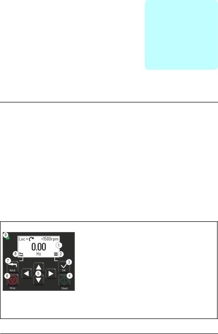
Control panel
By default, ACS 380 has an integrated panel. If required, you can use external control panels such as assistant control panel or a basic panel. For more information, refer
ACX-AP-x assistant control panel’s user’s manual (3AUA0000085685 [English]) or ACS-BP-S basic control panel’s user’s manual (3AXD50000032527 [English])
1.Display - shows the Home view as default.
2.Main menu.
3.OK button - open the Main menu, select and save settings.
4.Start button - start the drive.
5.Menu navigation buttons - move in the menus and set values.
6.Stop button - stop the drive.
7.Back button - open the Options menu, and move back in the menu.
8.Options menu.
9.Status light - green and red colors indicate the state and potential problems.
18 Control panel
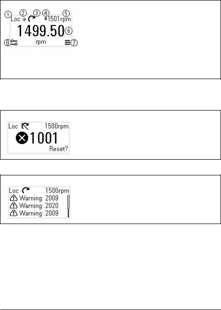
Home view and Message view
The Home view is the main view. Open the Main menu and Options menu from the Home view.
Home view
1.Control selection - local or remote
2.Local start/stop control - enabled
3.Rotation direction - forward or reverse
4.Local reference setting - enabled
5.Speed - target
6.Speed - current
7.Main menu - menu list
8.Options menu - quick access menu
The Message view shows fault and warning messages. If there is an active fault or warning, the panel shows the Message view directly.
You can open the Message view from the Options menu or Diagnostics submenu.
Message view: Fault
Fault messages require your immediate attention.
Check the code in the Fault messages table on page 402 to troubleshoot the problem.
Message view: Warning
Warning messages show possible problems.
Check the code in the Warning messages table on page 392 to troubleshoot the problem.
Control panel 19
Options menu and Main menu
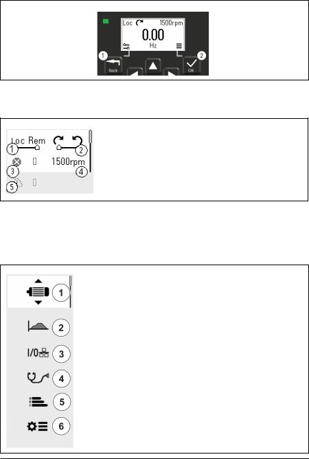
Options menu 
1.To open: press the Back button in the Home view.
Main menu
2.To open: press the OK button in the Home view.
Options menu
The Options menu is a quick access menu.
1.Control location - set to local or remote control
2.Rotation direction - set to forward or reverse
3.Active faults - view possible faults
4.Reference speed - set the reference speed
5.Active warnings - view possible warnings
Main menu
The Main menu is a scroll menu. The menu icons represent specific groups. The groups have submenus.
Note: You can define which Main menu items are visible (see parameter 49.30).
1.Motor data - motor parameters
2.Motor control - motor settings
3.Control macros
4.Diagnostics - faults, warnings, fault log and connection status
5.Energy efficiency - energy savings
6.Parameters - parameters

20 Control panel
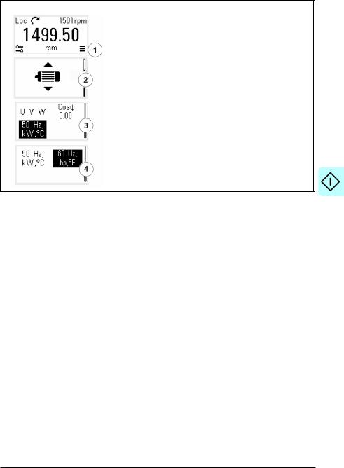
Submenus
The Main menu items have submenus. Some submenus also have menus and/or option lists. The content of the submenus depend on the drive type.
Motor Data
1.Motor type - AsynM, PMSM, SynRM
2.Control mode - Scalar, Vector
3.Nominal power
4.Nominal current
5.Nominal voltage
6.Nominal frequency
7.Nominal speed
8.Nominal torque
9.Phase order - U V W, U W V 10.Nominal Cosphi
11.Unit selection - SI or US units
Motor Data: Motor type
1.AsynM
2.PMSM
3.SynRM
Motor Data: Control mode
1.Scalar
2.Vector
Motor Data: Phase order
1.U V W
2.U W V
Motor Data: Unit selection
1.SI units
2.US units
Control panel 21
Motor Control
1.Start mode - Const time, Automatic
2.Stop mode - Coast, Ramp, DC hold
3.Acceleration time
4.Deceleration time
5.Maximum allowed speed
6.Maximum allowed current
7.Minimum allowed speed
Motor Control: Start modes
1.Const time
2.Automatic
Motor Control: Stop modes
1.Coast
2.Ramp
3.DC hold
Control macros |
The control macros available depends on the option module |
|
|
installed. |
|
|
1. ABB standard (2-wire) |
|
|
2. |
ABB limited (2-wire) |
|
3. |
Alternate |
|
4. Motor potentiometer |
|
|
5. PID |
|
|
6. Modbus RTU |
|
|
7. PROFIBUS |
|
|
8. PROFINET IO |
|
|
9. |
EthernetIP |
10.Modbus TCP 11.EtherCAT 12.CANopen

22 Control panel
Diagnostics
1.Active Fault - shows the fault code
2.Fault History - list of latest fault codes (newest first)
3.Active Warnings - shows the warning code
4.Connection Status - Fieldbus and I/O signals
Energy Efficiency
1.Saved energy in kWh
2.Saved money
3.Saved energy in MW
4.Saved money x 1000
5.Cost per kWh h
Parameters
1.Complete parameter list - groups menu with complete parameters and parameter levels
2.Modified parameter list
3.Parameter restore - reset to factory default parameters

Start-up, ID run and use 23
3
Start-up, ID run and use
Contents
•Start up the drive
•Do the identification (ID) run
•Start and stop the drive
•Change the rotation direction
•Set the speed or frequency reference
•Set the drive parameters
•Open Diagnostics
•Change the units
Note: In this chapter the drive uses an integrated panel to perform the start-up, ID run, and other actions. You can also perform these functions using an external control panel or a drive composer PC tool.
Start up the drive
1.Select the unit (international or US) and press OK.
The drive recognizes the connected adapter and sets the correct settings. This may take a few seconds depending on the adapter.
2.In the Motor data view, set the motor type: AsynM: Asynchronous motor
PMSM: Permanent magnet motor, or SynRM: Synchronous reluctance motor
3.Set the motor control mode:
Vector: Speed reference. This is suitable for most cases. The drive does an automatic stand-still ID run.

24 Start-up, ID run and use
Scalar: Frequency reference.
Use this mode when:
-The number of motors can change.
-The nominal motor current is less than 20% of the nominal drive current. Scalar mode is not recommended for permanent magnet motors.
4.Set the nominal motor values:
• Nominal power
• Nominal current
• Nominal voltage
• Nominal frequency
• Nominal speed
• Nominal torque (optional)
• Nominal cosphi
5.Examine the direction of the motor.
If it is necessary, set the motor direction with the Phase order setting or with the phase order of the motor cable.
6.In the Motor control view, set the start and stop mode.
7.Set the acceleration time and the deceleration time.
Note: The speed acceleration and deceleration ramp times are based on the value in parameter 46.01 Speed scaling/46.02 Frequency scaling.
8.Set the maximum and minimum speed or frequency. For more information, see parameters 30.11 Minimum speed /30.13 Minimum frequency and 30.12 Maximum speed/30.14 Maximum frequency on page 218.
9.In the Control macros view, select the applicable macro.
For units with a fieldbus adapter connected: you can see the fieldbus in the Control macros view. There are certain parameters that you need to change, eg. the station ID. See chapter Fieldbus control through a fieldbus adapter.
10.Tune the drive parameters to the application. You can use the Assistant control panel (ACS-AP-x), or the Drive Composer PC tool with the drive.

Start-up, ID run and use 25
Do the identification (ID) run
Background information
The drive automatically estimates motor characteristics using Standstill ID run when the drive is started for the first time, and after any motor parameter (group 99 Motor data) is changed. This is valid when:
•parameter 99.13 ID run requested selection is Standstill and
•parameter 99.04 Motor control mode selection isVector.
In most applications there is no need to perform a separate ID run. Select the ID run for demanding motor control connections. For example:
•permanent magnet motor (PMSM) is used
•drive operates near zero speed references, or
•operation at torque range above the motor nominal torque, over a wide speed range is needed.
Note: If you change the motor parameters after the ID run, you need to repeat the run.
Note: If you have already parameterized your application using scalar motor control mode and you need to change to vector:
•in the Motor data submenu, set Motor control to Vector, or set parameter 99.04 Motor control mode selection to Vector.
•for I/O controlled drive, check parameters in groups 22 Speed reference selection, 23 Speed reference ramp, 12 Standard AI, 30 Limits and 46 Monitoring/scaling settings.
•for torque controlled drive, check also parameters in group 26 Torque reference chain.
ID run steps
Warning! Make sure it is safe to run the procedure.
1.Open the Main menu.
2.Select the Parameters submenu.
3.Select All parameters.
4.Select 99 Motor data and press OK.
5.Select 99.13 ID run requested, select the wanted ID mode and press OK.
An AFF6 Identification run warning message is shown before you press Start. The panel LED starts to blink green to indicate an active warning.
6.Press Start to start the ID run.

26 Start-up, ID run and use
Do not to press any control panel keys during the ID run. If you need to stop the ID run, press Stop.
After the ID run is completed, the status light stops blinking. If the ID run fails, the panel shows the fault FF61 ID run.

Start-up, ID run and use 27
Start and stop the drive
1. Press the Start button to start the drive.
2. Press the Stop button to stop the drive.
Change the rotation direction
1.In the Options menu, move to the rotation direction item with the arrow buttons.
2.Press the OK button to change the rotation direction.
Set the speed or frequency reference
1.In the Options menu, move to the speed or frequency reference item and press OK.
2.Press the arrow buttons to edit the value.
3.Press the OK button to confirm the new value.

28 Start-up, ID run and use
Set the drive parameters
1.Select the Main menu from the Home view.
2.Scroll to Parameters, and press the OK button to open the submenu.
3.Select the complete parameters list with the arrow button and press the OK button, or
4.Select the modified parameters list with the arrow button and press the OK button.
5.Select the parameter and press the OK button.
The parameters are shown in respective groups. The first two digits of the parameter number represent the parameter group. For example, parameters starting with 30 are in the Limits group.
See chapter Parameters for more information.
Open Diagnostics
1.Select the Main menu from the Home view.
2.Scroll to Diagnostics and press the OK button to open the submenu.
3.Select the warning or fault with the arrow button and press the OK button.
See chapter Fault tracing for more information.
Start-up, ID run and use 29
Change the units
1.Select the Main menu from the Home view.
2.Scroll to Motor data and press the OK button to open the submenu.
3.Scroll to the unit selection item and press the OK button.
4.Select the unit with the arrow button, then press the OK button.
You can see the selected unit on the Home view.

30 Start-up, ID run and use
Loading...