


ACS880-0500-3
Table of contents
 Loading...
ABB ACS880-0500-3, ACS880-1510-3, ACS880-1000-3, ACS880-0750-3, ACS880-3770-3 Hardware Manual
...
—
ABB INDUSTRIAL DRIVES
ACS880-607 3-phase brake units
Hardware manual


ACS880-607 3-phase brake units
Hardware manual
Table of contents
3. Mechanical installation
5. Electrical installation
8. Start-up
© 2019 ABB Oy. All Rights Reserved. 3AXD50000022034 Rev D
EN
EFFECTIVE: 2019-04-29


Table of contents
1 Introduction to the manual
2 Operation principle and hardware description
Table of contents 5
9Contents of this chapter . ... ... ... ... ... ... ... ............. . ... . .. . ... . ... ... . ... ... . ... . .. . ... . ..
9Applicability . . ... ... . ... . .. . ... . ... ... . ... ... . ... . .. . ... . ... ... . ... ... . ... ... . ... . .. . ... . ... ... . ... .
9Safety instructions ... ... . ... . .. . ... . ... ... . ... ... . ... . .. . ... . .. . ... . ... ... . ... ... . ... . .. . ... . ... ..
9Target audience .... . ... ... . ... . .. . ... . ... ... . ... ... . ... . .. . ... . .. . ... . ... ... . ... ... . ... . .. . ... . ...
10Related manuals ... ... . ... ... . ... . .. . ... . ... ... . ... ... . ... ... . ... . .. . ... . ... ... . ... ... . ... . .. . ... .
10Categorization by frame size and option code . ... . .. . ... . ... ... . ... ... . ... ... . ... . .. . ... . ...
11Use of component designations . ... . ... . .. . ... . ... ... . ... ... . ... ... . ... . .. . ... . ... ... . ... ... . ..
11Terms and abbreviations . . .. . ... . .. . ... . ... ... . ... ... . ... . .. . ... . ... ... . ... ... . ... ... . ... . .. . ... .
13Contents of this chapter . ... . ... . .. . ... . ... ... . ... ... . ... . .. . ... . ... ... . ... ... . ... ... . ... . .. . ... . .
13Product overview ... ... . ... ... . ... . .. . ... . ... ... . ... ... . ... ... . ... . .. . ... . ... ... . ... ... . ... . .. . ... .
13Operation principle ... ... . ... ... . ... . .. . ... . ... ... . ... ... . ... . .. . ... . ... ... . ... ... . ... ... . ... . .. . ..
13Simplified main circuit diagram of the drive system .. ... . ... . .. . ... . ... ... . ... ... . ... . .. . ...
15Layout drawings ... ... . ... ... . ... . .. . ... . ... ... . ... ... . ... ... . ... . .. . ... . ... ... . ... ... . ... ... . ... . .
18Frame R8i layout .... . ... ... . ... ... . ... . .. . ... . ... ... . ... ... . ... ... . ... . .. . ... . ... ... . ... ... . ... . ..
19Brake chopper module connectors . ... . ... . .. . ... . ... ... . ... ... . ... ... . ... . .. . ... . ... ... . ... ...
19Connectors X50…X53 ... ... . ... . .. . ... . ... ... . ... ... . ... ... . ... . .. . ... . ... ... . ... ... . ... ... . .
20Fibre optic connectors .... . ... ... . ... . .. . ... . .. . ... . ... ... . ... ... . ... . .. . ... . ... ... . ... ... . ...
20Overview of power and control connections .... ... . ... . .. . ... . .. . ... . ... ... . ... ... . ... . .. . ...
21Brake unit control devices . ... . ... . .. . ... . ... ... . ... ... . ... ... . ... . .. . ... . ... ... . ... ... . ... ... . ..
22Overview of the control connections of the BCU control unit . ... ... . ... ... . ... . .. . ... . .
22The control panel .... . ... ... . ... ... . ... . .. . ... . ... ... . ... ... . ... ... . ... . .. . ... . ... ... . ... ... . ..
23Control by PC tools . ... . ... . .. . ... . .. . ... . ... ... . ... ... . ... . .. . ... . ... ... . ... ... . ... ... . ... . ..
23Fieldbus control ... ... . ... ... . ... . .. . ... . ... ... . ... ... . ... ... . ... . .. . ... . ... ... . ... ... . ... . .. . ..
23DC switch and charging switch .. . ... ... . ... ... . ... . .. . ... . ... ... . ... ... . ... . .. . ... . ... ... . ..
23Type designation labels .. . ... . ... ... . ... ... . ... . .. . ... . ... ... . ... ... . ... ... . ... . .. . ... . ... ... . ...
24Brake unit type designation label .. . ... . .. . ... . .. . ... . ... ... . ... ... . ... . .. . ... . ... ... . ... ...
24Brake chopper module type designation label .... ... . ... . .. . ... . .. . ... . ... ... . ... ... . ... .
25Brake unit type designation key .. . ... ... . ... . .. . ... . ... ... . ... ... . ... . .. . ... . .. . ... . ... ... . ... .
28Brake chopper module type designation key .... ... . ... ... . ... . .. . ... . ... ... . ... ... . ... . .. . ..
3 Mechanical installation
4 Guidelines for planning the electrical installation
31Contents of this chapter . ... . ... . .. . ... . ... ... . ... ... . ... . .. . ... . ... ... . ... ... . ... ... . ... . .. . ... . .
31Brake units ... ... . ... ... . ... . .. . ... . ... ... . ... ... . ... ... . ... . .. . ... . ... ... . ... ... . ... . .. . ... . .. . ... .
31User-defined brake resistors .... . ... ... . ... ... . ... . .. . ... . ... ... . ... ... . ... . .. . ... . ... ... . ... ...
33Contents of this chapter . ... . ... . .. . ... . ... ... . ... ... . ... . .. . ... . ... ... . ... ... . ... ... . ... . .. . ... . .
33Limitation of liability .... . ... ... . ... . .. . ... . ... ... . ... ... . ... . .. . ... . .. . ... . ... ... . ... ... . ... . .. . ...
33Generic guidelines ... ... . ... ... . ... . .. . ... . ... ... . ... ... . ... ... . ... . .. . ... . ... ... . ... ... . ... . .. . ..
33Selecting the brake resistors . ... . ... . .. . ... . ... ... . ... ... . ... . .. . ... . .. . ... . ... ... . ... ... . ... . ..
34Selecting and routing the brake resistor cables . ... . .. . ... . ... ... . ... ... . ... . .. . ... . .. . ... . ..
34Typical resistor cable sizes .... . .. . ... . ... ... . ... ... . ... ... . ... . .. . ... . ... ... . ... ... . ... . .. . .

6 Table of contents
5 Electrical installation
34Minimizing electromagnetic interference .... . ... . .. . ... . ... ... . ... ... . ... ... . ... . .. . ... . ...
34Maximum cable length .... . ... ... . ... ... . ... . .. . ... . ... ... . ... ... . ... ... . ... . .. . ... . ... ... . ...
34Placing the brake resistors . ... . ... . .. . ... . ... ... . ... ... . ... ... . ... . .. . ... . ... ... . ... ... . ... ... . .
35Selecting the resistor thermal switch cable .... ... . ... . .. . ... . ... ... . ... ... . ... . .. . ... . ... ... .
35Protecting the system against thermal overload .... . .. . ... . ... ... . ... ... . ... ... . ... . .. . ... . .
35Operation principle ... ... . ... ... . ... . .. . ... . ... ... . ... ... . ... . .. . ... . ... ... . ... ... . ... ... . ... . .
35Protecting the system against short-circuits .. . ... . ... ... . ... ... . ... ... . ... . .. . ... . ... ... . ... .
37Contents of this chapter . ... . ... . .. . ... . ... ... . ... ... . ... . .. . ... . ... ... . ... ... . ... ... . ... . .. . ... . .
38Electrical safety precautions .... . ... . .. . ... . ... ... . ... ... . ... ... . ... . .. . ... . ... ... . ... ... . ... ...
39General notes ... ... . ... ... . ... . .. . ... . ... ... . ... ... . ... ... . ... . .. . ... . ... ... . ... ... . ... . .. . ... . ...
39Static electricity ... ... . ... . .. . ... . ... ... . ... ... . ... . .. . ... . .. . ... . ... ... . ... ... . ... . .. . ... . ... ..
39Optical components ... ... . ... . .. . ... . .. . ... . ... ... . ... ... . ... . .. . ... . ... ... . ... ... . ... ... . ... .
39Checking the insulation of brake resistor and resistor cable ... . ... ... . ... . .. . ... . ... ... . ..
40Connecting the brake resistor cables and thermal switch .. ... . ... . .. . ... . ... ... . ... ... . ...
40Connection diagram ... ... . ... ... . ... . .. . ... . ... ... . ... ... . ... ... . ... . .. . ... . ... ... . ... ... . ...
41Connection procedure of the resistor cables .... ... . ... . .. . ... . .. . ... . ... ... . ... ... . ... . ..
41Connection procedure of the thermal switch cable . ... . .. . ... . ... ... . ... ... . ... . .. . ... . ..
43Connecting a PC .... . ... ... . ... ... . ... . .. . ... . ... ... . ... ... . ... ... . ... . .. . ... . ... ... . ... ... . ... . ..
6 Control units of the drive
7 Installation checklist of the drive
8 Start-up
45Contents of this chapter . ... . ... . .. . ... . ... ... . ... ... . ... . .. . ... . ... ... . ... ... . ... ... . ... . .. . ... . .
45General . . ... ... . ... . .. . ... . .. . ... . ... ... . ... ... . ... . .. . ... . ... ... . ... ... . ... ... . ... . .. . ... . ... ... . ..
46BCU-x2 control unit layout and connections .... ... . ... . .. . ... . ... ... . ... ... . ... ... . ... . .. . ...
48Default I/O diagram of the brake control unit .. . .. . ... . ... ... . ... ... . ... . .. . ... . ... ... . ... ... .
49External power supply for the control unit (XPOW) .. . ... ... . ... ... . ... ... . ... . .. . ... . ... ... .
49The XD2D connector .... . ... ... . ... . .. . ... . .. . ... . ... ... . ... ... . ... . .. . ... . ... ... . ... ... . ... ... . .
50Safe torque off (XSTO, XSTO OUT) .. . ... . ... ... . ... ... . ... . .. . ... . ... ... . ... ... . ... ... . ... . ..
50FSO-xx safety functions module connection (X12) .... . .. . ... . ... ... . ... ... . ... . .. . ... . ... ..
50SDHC memory card slot . ... . ... ... . ... . .. . ... . ... ... . ... ... . ... ... . ... . .. . ... . ... ... . ... ... . ... .
51Connector data ... ... . ... ... . ... . .. . ... . ... ... . ... ... . ... ... . ... . .. . ... . ... ... . ... ... . ... . .. . ... . ..
53BCU-x2 ground isolation diagram . ... . ... . .. . ... . ... ... . ... ... . ... ... . ... . .. . ... . ... ... . ... .
55Contents of this chapter . ... . ... . .. . ... . ... ... . ... ... . ... . .. . ... . ... ... . ... ... . ... ... . ... . .. . ... . .
55Checklist . . ... ... . ... . .. . ... . .. . ... . ... ... . ... ... . ... . .. . ... . ... ... . ... ... . ... ... . ... . .. . ... . ... ... .
57Contents of this chapter . ... . ... . .. . ... . ... ... . ... ... . ... . .. . ... . ... ... . ... ... . ... ... . ... . .. . ... . .
57Start-up procedure ... ... . ... . .. . ... . .. . ... . ... ... . ... ... . ... . .. . ... . ... ... . ... ... . ... ... . ... . .. . ..
57Start-up procedure ... ... . ... . .. . ... . .. . ... . ... ... . ... ... . ... . .. . ... . ... ... . ... ... . ... ... . ... . .
9 Fault tracing
59Contents of this chapter . ... . ... . .. . ... . ... ... . ... ... . ... . .. . ... . ... ... . ... ... . ... ... . ... . .. . ... . .
59Fault indications ... ... . ... . .. . ... . ... ... . ... ... . ... ... . ... . .. . ... . ... ... . ... ... . ... ... . ... . .. . ... . .
60LEDs . . ... ... . ... ... . ... . .. . ... . ... ... . ... ... . ... . .. . ... . ... ... . ... ... . ... ... . ... . .. . ... . ... ... . ... ..
60Control panel and panel platform/holder LEDs .... ... . ... . .. . ... . ... ... . ... ... . ... . .. . ...
60Control unit LEDs .... . ... ... . ... . .. . ... . .. . ... . ... ... . ... ... . ... . .. . ... . ... ... . ... ... . ... ... . ..
61R8i module LEDs .... . ... ... . ... ... . ... . .. . ... . ... ... . ... ... . ... ... . ... . .. . ... . ... ... . ... ... . ..

10 Maintenance
11 Technical data
Table of contents 7
61Warning and fault messages ... . .. . ... . ... ... . ... ... . ... . .. . ... . .. . ... . ... ... . ... ... . ... . .. . ... .
617-segment display of the brake control unit . ... . .. . ... . ... ... . ... ... . ... ... . ... . .. . ... . ... ... .
63Contents of this chapter . ... . ... . .. . ... . ... ... . ... ... . ... . .. . ... . ... ... . ... ... . ... ... . ... . .. . ... . .
63Reference to maintenance instructions . . .. . ... . ... ... . ... ... . ... ... . ... . .. . ... . ... ... . ... ... . .
64Replacing brake chopper and brake resistor fuses – bottom exit ..... ... . ... ... . ... . .. . ..
65Replacing brake chopper and brake resistor fuses – top exit ..... ... . ... ... . ... . .. . ... . ...
67Contents of this chapter . ... . ... . .. . ... . ... ... . ... ... . ... . .. . ... . ... ... . ... ... . ... ... . ... . .. . ... . .
67Ratings . . ... ... . ... . .. . ... . .. . ... . ... ... . ... ... . ... . .. . ... . ... ... . ... ... . ... ... . ... . .. . ... . ... ... . ..
69Definitions . . ... ... . ... . .. . ... . ... ... . ... ... . ... . .. . ... . .. . ... . ... ... . ... ... . ... . .. . ... . ... ... . ..
70Derating . . ... ... . ... . .. . ... . .. . ... . ... ... . ... ... . ... . .. . ... . ... ... . ... ... . ... ... . ... . .. . ... . ... ..
70Input and output voltages . . .. . ... . ... ... . ... ... . ... ... . ... . .. . ... . ... ... . ... ... . ... ... . ... . .. . ...
71Type equivalence table .. . ... . ... ... . ... ... . ... . .. . ... . ... ... . ... ... . ... ... . ... . .. . ... . ... ... . ...
72Typical resistor cable sizes .... . .. . ... . ... ... . ... ... . ... . .. . ... . .. . ... . ... ... . ... ... . ... . .. . ... . .
73Maximum cable length .... . ... ... . ... ... . ... . .. . ... . ... ... . ... ... . ... ... . ... . .. . ... . ... ... . ...
73Fuses . . ... ... . ... ... . ... . .. . ... . ... ... . ... ... . ... . .. . ... . ... ... . ... ... . ... ... . ... . .. . ... . ... ... . ... .
74Dimensions, weights and free space requirements .... ... . ... . .. . ... . ... ... . ... ... . ... ... . ..
75Losses, cooling data and noise .. . ... ... . ... . .. . ... . .. . ... . ... ... . ... ... . ... . .. . ... . ... ... . ... ..
76Resistor connection ... ... . ... ... . ... . .. . ... . ... ... . ... ... . ... . .. . ... . .. . ... . ... ... . ... ... . ... . .. .
76Efficiency .. . ... . .. . ... . ... ... . ... ... . ... ... . ... . .. . ... . ... ... . ... ... . ... . .. . ... . .. . ... . ... ... . ... ...
76Protection classes ... ... . ... . .. . ... . .. . ... . ... ... . ... ... . ... . .. . ... . ... ... . ... ... . ... ... . ... . .. . ..
76Ambient conditions ... ... . ... . .. . ... . ... ... . ... ... . ... ... . ... . .. . ... . ... ... . ... ... . ... ... . ... . .. . .
78Materials . . ... ... . ... . .. . ... . .. . ... . ... ... . ... ... . ... . .. . ... . ... ... . ... ... . ... ... . ... . .. . ... . ... ... .
78Standards . . ... ... . ... . .. . ... . ... ... . ... ... . ... ... . ... . .. . ... . ... ... . ... ... . ... . .. . ... . ... ... . ... ...
78Markings . . ... ... . ... ... . ... . .. . ... . ... ... . ... ... . ... ... . ... . .. . ... . ... ... . ... ... . ... . .. . ... . ... ... .
79Tightening torques . ... ... . ... ... . ... . .. . ... . ... ... . ... ... . ... ... . ... . .. . ... . ... ... . ... ... . ... ... . .
79Electrical connections ... ... . ... . .. . ... . ... ... . ... ... . ... ... . ... . .. . ... . ... ... . ... ... . ... ... . .
79Mechanical connections ... ... . ... ... . ... . .. . ... . ... ... . ... ... . ... ... . ... . .. . ... . ... ... . ... ...
79Insulation supports ... ... . ... . .. . ... . .. . ... . ... ... . ... ... . ... . .. . ... . ... ... . ... ... . ... ... . ... . .
79Cable lugs ... ... . ... ... . ... ... . ... . .. . ... . ... ... . ... ... . ... . .. . ... . .. . ... . ... ... . ... ... . ... . .. . .
79Disclaimers . . ... ... . ... ... . ... . .. . ... . ... ... . ... ... . ... . .. . ... . .. . ... . ... ... . ... ... . ... . .. . ... . ... .
79Generic disclaimer ... ... . ... ... . ... . .. . ... . ... ... . ... ... . ... ... . ... . .. . ... . ... ... . ... ... . ... ..
80Cybersecurity disclaimer ... ... . ... ... . ... . .. . ... . ... ... . ... ... . ... ... . ... . .. . ... . ... ... . ... ..
12 Dimension drawings
Further information
81Contents of this chapter . ... . ... . .. . ... . ... ... . ... ... . ... . .. . ... . ... ... . ... ... . ... ... . ... . .. . ... . .
82Dimension drawing – bottom exit .. . ... ... . ... . .. . ... . ... ... . ... ... . ... ... . ... . .. . ... . ... ... . ...
84Dimension drawing – top exit .. . ... ... . ... . .. . ... . .. . ... . ... ... . ... ... . ... . .. . ... . ... ... . ... ... .

8

Introduction to the manual
Introduction to the manual 9
1
Contents of this chapter
This chapter gives basic information on the manual.
Applicability
The manual is applicable to ACS880-607 3-phase brake units that form a part of an ACS880
multidrive system.
Safety instructions
Follow all safety instructions delivered with the drive.
• Read the complete safety instructions before you install, commission, use or service
the drive. The complete safety instructions are given in ACS880 multidrive cabinets and
modules safety instructions (3AUA0000102301 [English]).
• Read the software-function-specific warnings and notes before changing the default
settings of a function. For each function, the warnings and notes are given in the section
describing the related user-adjustable parameters.
• Read the task-specific safety instructions before starting the task. See the section
describing the task.
Target audience
This manual is intended for people who plan the installation, install, start up and service the
drive, or create instructions for the end user of the drive concerning the installation and
maintenance of the drive.
Read the manual before working on the drive. You are expected to know the fundamentals
of electricity, wiring, electrical components and electrical schematic symbols.

10 Introduction to the manual
The manual is written for readers worldwide. Both SI and imperial units are shown.
Related manuals
CodeManual
General manuals
3AUA0000102301ACS880 multidrive cabinets and modules safety instructions
3AUA0000102324ACS880 multidrive cabinets and modules electrical planning instructions
3AUA0000101764ACS880 multidrive cabinets mechanical installation instructions
Supply unit manuals
3AUA0000130644ACS880-207 IGBT supply units hardware manual
3AUA0000131562ACS880 IGBT supply control program firmware manual
3AUA0000102453ACS880-307 +A003 diode supply units hardware manual
3AXD50000011408ACS880-307 +A018 diode supply units hardware manual
3AUA0000103295ACS880 diode supply control program firmware manual
3AXD50000020546ACS880-907 regenerative rectifier units hardware manual
3AXD50000020827ACS880 regenerative rectifier control program firmware manual
Inverter unit manuals
3AUA0000102519ACS880-107 inverter units hardware manual
3AUA0000085967ACS880 primary control program firmware manual
3AUA0000098062ACS880 primary control program quick start-up guide
Manuals for application programs (Crane, Winder, etc.)
Brake unit and DC/DC converter unit manuals
3AUA0000102559ACS880-607 1-phase brake units hardware manual
3AXD50000022034ACS880-607 3-phase brake units hardware manual
3AXD50000020967ACS880 (3-phase) brake control program firmware manual
3AXD50000023644ACS880-1607 DC/DC converter units hardware manual
3AXD50000024671ACS880 DC/DC converter control program firmware manual
Option manuals
3AUA0000085685ACS-AP-x assistant control panels user’s manual
3AUA0000094606Drive composer start-up and maintenance PC tool user’s manual
Manuals for I/O extension modules, fieldbus adapters, safety options etc.
You can find manuals on the Internet. See www.abb.com/drives/documents. For manuals
not available in the document library, contact your local ABB representative.
Categorization by frame size and option code
Some descriptions, instructions, technical data and dimensional drawings which concern
only certain brake units are marked with the symbol of the frame size such as 4×R8i. The
marking derives from the quantity and basic construction of the brake chopper modules that
form the brake unit. For example, frame size 2×R8i indicates that the brake unit consists of
two frame size R8i brake chopper modules connected in parallel.
The frame size is marked on the type designation labels. The frame size of each brake
chopper module is also shown in the technical data.

Introduction to the manual 11
The instructions and technical data which concern only certain optional selections are marked
with option codes (such as +E210). The options included in the drive can be identified from
the option codes visible on the type designation label.
Use of component designations
Some device names in the manual include the item designation in brackets, for example
[Q20], to make it possible to identify the components in the circuit diagrams of the drive.
Terms and abbreviations
DescriptionTerm/
Abbreviation
Type of control boardBCON
Type of control unitBCU
Control board for direct-on-line cooling fanBDFC
Internal power supply board in frame R8i modulesBDPS
Control and power supply board for speed-controlled cooling fanBFPS
Brake chopper
Brake chopper module
Brake resistor
Cubicle
Multidrive
Parameter
Conducts the surplus energy from the intermediate circuit of the drive to the brake
resistor when necessary. The chopper operates when the DC link voltage exceeds
a certain maximum limit. The voltage rise is typically caused by deceleration
(braking) of a high inertia motor.
Brake chopper enclosed in a metal frame or housing. Intended for cabinet installation.
Dissipates the drive surplus braking energy conducted by the brake chopper to
heat
Brake chopper modules under control of one control board, and related accessoriesBrake unit
Circuit board in which the control program runsControl board
Control board built in a housing (often rail-mountable)Control unit
One section of a cabinet-installed drive. A cubicle is typically behind a door of its
own.
DC circuit between rectifier and inverterDC link
Frequency converter for controlling AC motorsDrive
Electromagnetic compatibilityEMC
Physical size of the drive or power moduleFrame, frame size
DC circuit between rectifier and inverterIntermediate circuit
Drive for controlling several motors which are typically coupled to the same machinery. Includes one supply unit, and one or several inverter units.
In the drive control program, user-adjustable operation instruction to the drive, or
signal measured or calculated by the drive.
In some (for example fieldbus) contexts, a value that can be accessed as an object,
eg, variable, constant, or signal.
Drive for controlling one motorSingle drive
Type of memory unit, attached to the control unitZMU

12

Operation principle and hardware description 13
2
Operation principle and hardware description
Contents of this chapter
This chapter describes the operation principle and construction of the brake unit.
Product overview
ACS880-607 is an air-cooled cabinet-installed brake unit, which forms a part of an ACS880
multidrive system. As standard, it includes brake chopper(s). Brake resistors are external.
Operation principle
The brake chopper handles the energy generated by a decelerating motor. The extra energy
increase the DC link voltage. The chopper connects the brake resistor to the DC link of the
drive whenever the voltage exceeds an activation limit. The energy consumption by the
resistor losses lowers the voltage until the resistor can again be disconnected.
Typically, a drive system is equipped with a brake chopper or brake choppers if
• high capacity braking is needed and the drive cannot be equipped with a regenerative
supply unit
• a backup for the regenerative supply unit is needed.
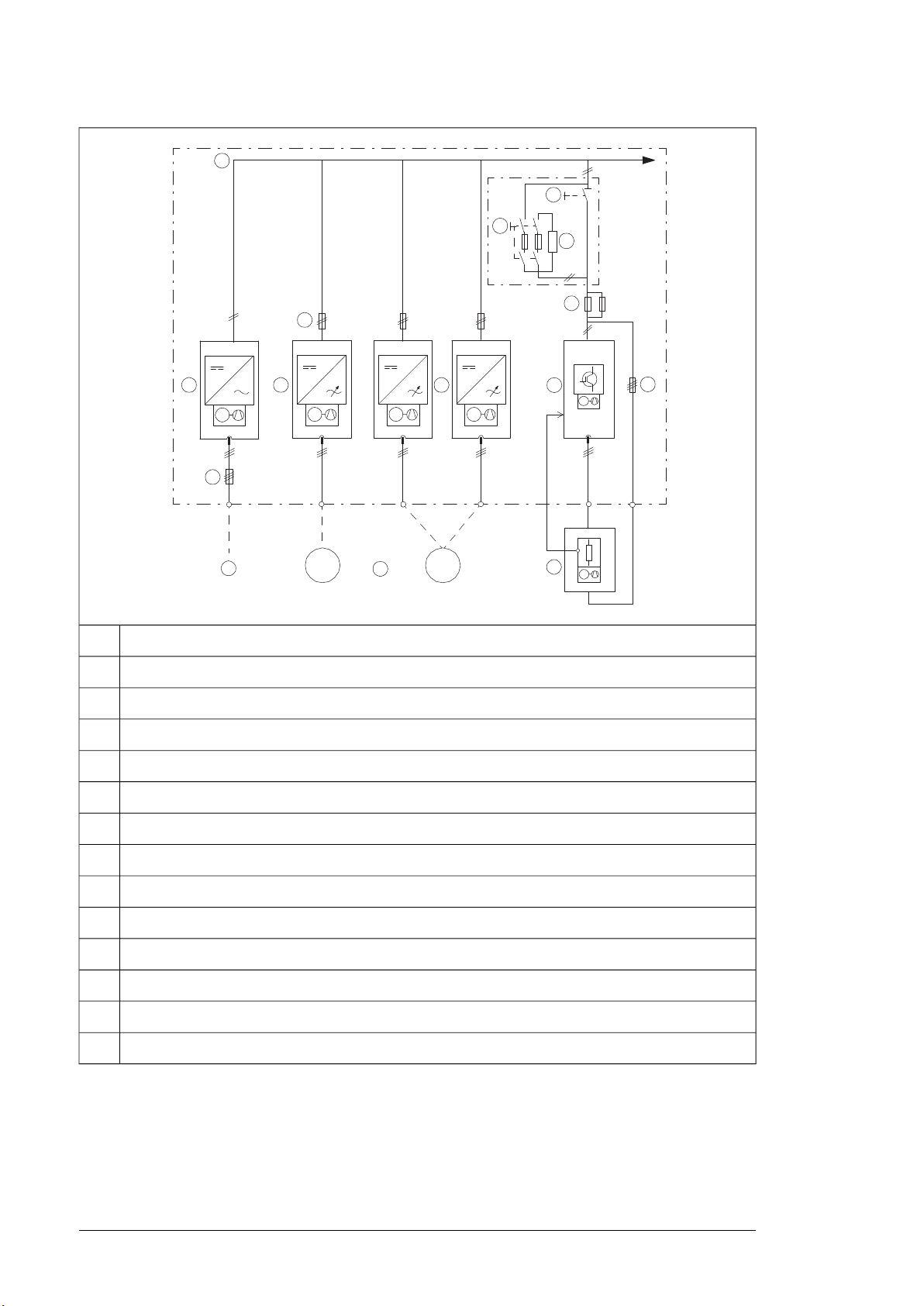
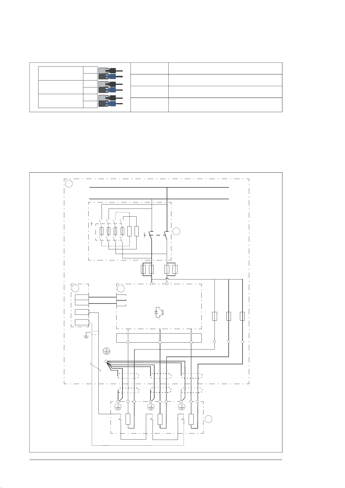
Simplified main circuit diagram of the drive system
This diagram shows a typical common DC bus drive system.
0
000
0
a
0
a
0
0
t°
14 Operation principle and hardware description
AC supply1
Input (AC) fuses2
Supply unit3
DC bus4
Inverter DC fuses (with or without a DC switch/disconnector)5
Inverter units (in this example, one of the two units consists of two inverter modules connected in parallel)6
Brake chopper fuses7
Brake unit8
Brake resistors (user-defined or option +D151)9
Brake resistor fuses10
Motor(s)11
DC switch/disconnector (part of option +F286)12
Charging circuit switch with fuses (part of option +F286)13
Charging resistors (part of option +F286)14
The supply unit connects to the AC supply network. The supply unit converts the AC voltage
into DC. The DC voltage is distributed through the DC bus to all inverter and brake units.
The inverter unit, consisting of one or more inverter modules, converts the DC back to AC
that rotates the motor. The brake unit, consisting of one or more brake chopper modules,
conveys energy to brake resistors whenever needed.
Operation principle and hardware description 15
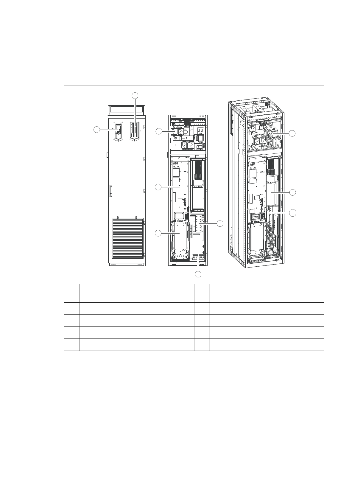
Layout drawings
The figure below shows the components of the brake chopper cubicle with bottom entry
and exit of cables and shrouds removed.
Cable entries for brake resistor and control
6Control panel (option +J400)1
cables
Terminals for brake resistor cable connection7Drive monitoring display (option +J401)2
Brake resistor fuses8Brake chopper fuses3
BCU-x2 control unit9Brake chopper module4
Cabinet heater (option +G300)10Brake chopper cooling fan5

1
2
3
4
5
6
7
9
10
11
12
8
13
16 Operation principle and hardware description
The figure below shows the components of the brake chopper cubicle with bottom entry
and exit of cables and shrouds removed – option +F286 included.
Brake resistor fuses8Control panel (option +J400)1
2
BCU-x2 control unit9DC switch/disconnector handle (part of option
+F286)
3
Terminals for brake resistor cable connection10Charging circuit switch fuse handle (part of op-
tion +F286)
Cable entries for brake resistor and control
11Drive monitoring display (option +J401)4
cables.
Brake chopper fuses12Charging circuit fuses5
Cabinet heater (option +G300)13Brake chopper module6
Brake chopper cooling fan7

Operation principle and hardware description 17
The figure below shows the components of the brake chopper cubicles with top entry and
exit of cables and shrouds removed.
Cable entries for brake resistor and control
6
cables
Terminals for brake resistor cable connection7Control panel (option +J400)1
Brake resistor fuses8Drive monitoring display (option +J401)2
Cabinet fans9Brake chopper fuses3
BCU-x2 control unit10Brake chopper module4
Cabinet heater (option +G300)11Brake chopper cooling fan5
A
B
1
8
10
5
7
12
3
2
9
4
6
5
11
18 Operation principle and hardware description
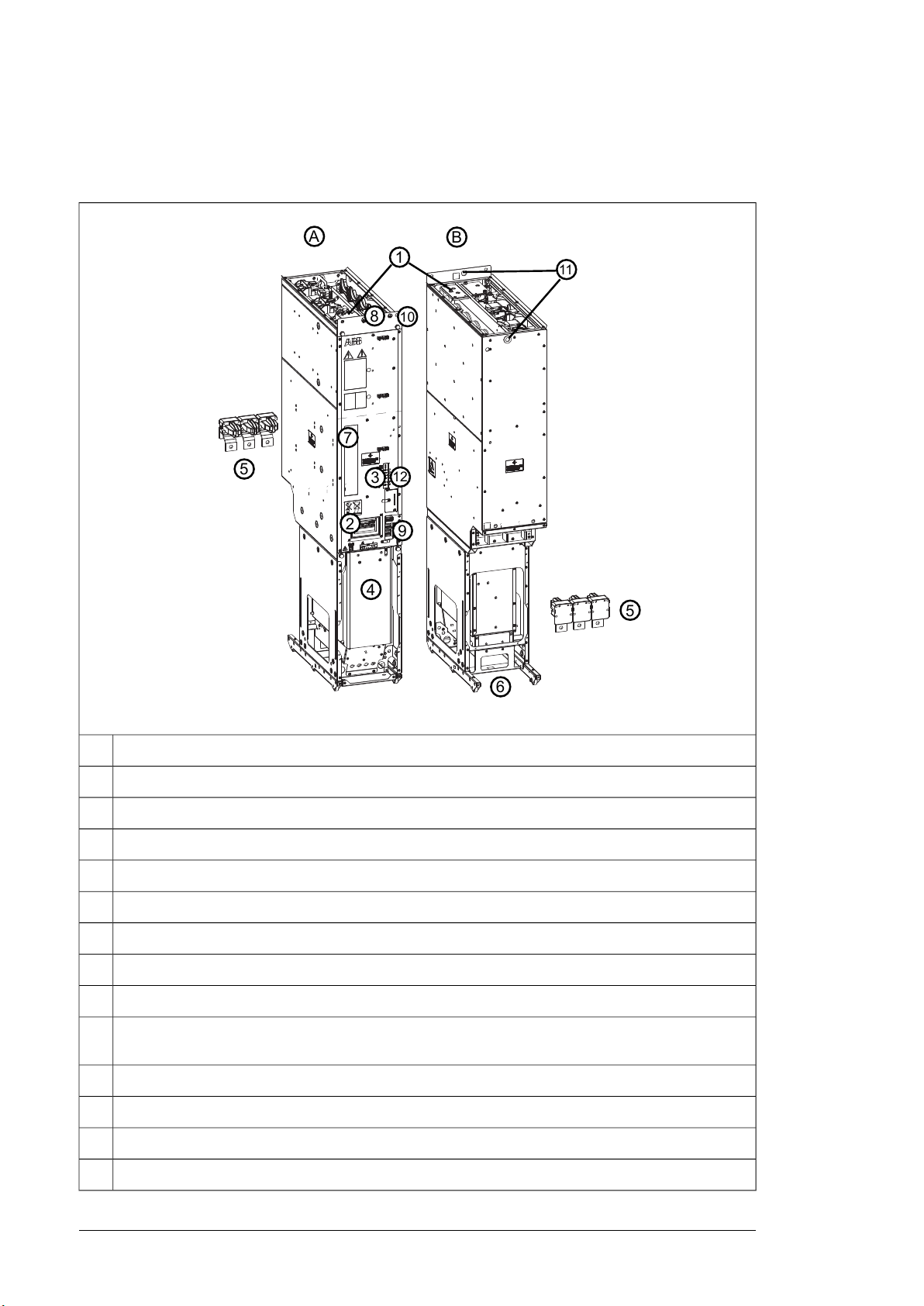
Frame R8i layout
This figure shows the layout of the R8i module.
R8i module, frontA
R8i module, backB
DC busbars1
Handle2
LEDs and fiber optic connectors3
Fan (standard speed-controlled fan shown; a direct-on-line fan is available as option +C188)4
Quick connector (three phases). The counterpart is fastened to the cabinet behind the module.5
Wheels6
Type designation label7
Terminal block [X50] (power supply for internal boards and module heating element, option +C183; DOL
8
fan supply, option +C188)
Connectors [X51], [X52], [X53]9
The unpainted grounding point (PE) between module frame and cabinet frame.10
Lifting eyes11
Circuit board compartment fan12

STO OUT
X51
FE
GND
24V
GND
24V
STO IN
X52
FE
GND
24V
GND
24V
24V OUT
X53
FE
24V
GND
24V
GND
Operation principle and hardware description 19
Brake chopper module connectors
■ Connectors X50…X53
Connector X50
Not in use.9
N8
L7
Not in use.6
N5
L4
W3
V2
U1
115/230 V AC (50/60 Hz) input for optional heating element
(+C183).
Not in use in brake chopper modules.
115/230 V AC 50 Hz input for internal power supply (BDPS)
(115 V AC 60 Hz with option +G304).
400 V AC (50/60 Hz) supply for optional DOL (direct-online)
cooling fan (option +C188).
Note:
In modules without +C188, the DOL wiring is present but not
in use.
Connectors X51, X52, X53
X51
OUT
STO INX52
24V OUTX53
Note:
The Safe torque off (STO) safety function is only
implemented in inverter units. Therefore, the STO
function cannot be used in supply, rectifier, DC/DC
converter and brake units. In these units, de-energizing any connection of STO IN (X52) connector
stops the unit. Note that this stop is not safety related and must not be used for safety function
purposes.
Not in use.STO
STO connectors of the module. Must be connected to
24 V DC for the module to
start.
24 V DC for BCU and for
STO IN to enable the module operation.
BSFC
V50
V60
BFPS
V30
V40
BCU
V10
V20
9 :8
'&'&
3(
'&
'&
t
t
t
5 5 5
9
',
97
95
9
9
5 5 5
20 Operation principle and hardware description
■ Fibre optic connectors
DescriptionName
Charging controller connection (option +F286).BSFC
Fan control connection (to fan control box).BFPS
Control unit connection.BCU
Overview of power and control connections
The diagram below shows the power and control connections of the brake unit consisting
of one 3-phase brake chopper module. For parallel-connected brake chopper modules, the
brake resistors are connected to each brake chopper module also as shown below. Each
parallel-connected brake chopper module has a dedicated control unit.

Operation principle and hardware description 21
Brake chopper cubicle1
DC switch/disconnector with charging circuit (option +F286)2
Control unit3
Brake chopper module4
Brake resistors (user-defined or option +D151)5
Brake unit control devices
Each brake chopper module employs a dedicated control unit (BCU) that contains the BCON
board with basic I/Os and slots for optional modules. A fiber optic link connects the BCU to
the brake chopper module.
1
2
3
4
5
6
7
F
X
X
F
X
X
F
X
X
X
8
CLOSE
9
10
22 Operation principle and hardware description
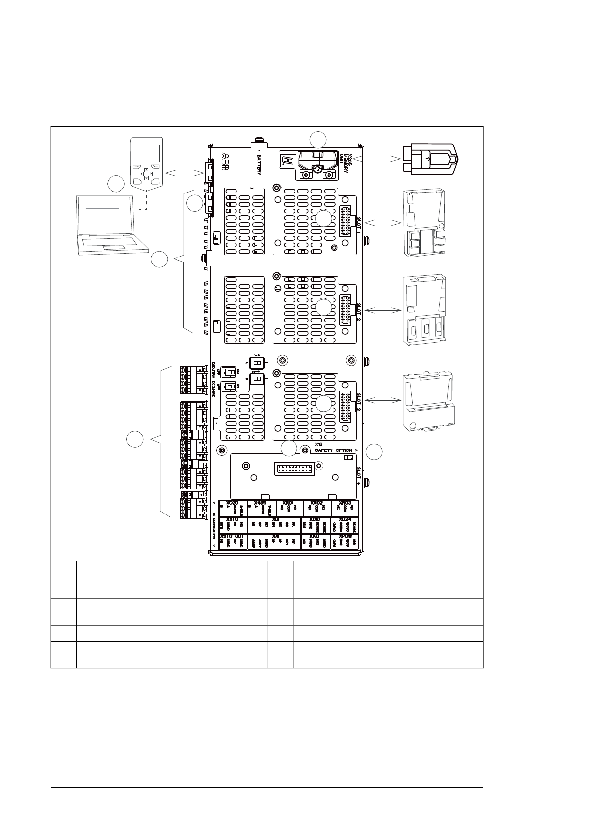
■ Overview of the control connections of the BCU control unit
The diagram shows the control connections and interfaces of the BCU control unit.
1
fieldbus communication modules can be inserted
2
into slots 1, 2 and 3.
3
■ The control panel
Control panel.7Analog and digital I/O extension modules and
Fiber optic links to power modules (inverter,
8Memory unit4
supply, brake or converter)
Ethernet port. Not in use.9Slot 4 for RDCO-0x5
Safety option interface. Only in use for the invert-
10Terminal blocks.6
er units.
The control panel (option +J400) is the user interface of the brake unit, providing the essential
controls such as reset, and the parameter settings for the control program.
The control panel is mounted on a platform on the brake chopper cubicle door.
For details on the control panel, see ACS-AP-x Assistant control panels user’s manual
(3AUA0000085685 [English]).

Operation principle and hardware description 23
■ Control by PC tools
There is a USB connector on the front of the panel that can be used to connect a PC to the
drive.
■ Fieldbus control
The unit can be controlled through a fieldbus interface if it is equipped with an optional
fieldbus adapter, and when the control program has been configured for fieldbus control by
parameters. For information on the parameters, see the firmware manual.
■ DC switch and charging switch
DC switch/disconnector (option +F286)
The brake unit can optionally be equipped with DC switch/disconnectors which allow the
isolation of the brake chopper modules from the DC bus. When a brake chopper module is
reconnected to the DC bus, its DC capacitors are automatically charged through a charging
circuit.
The status of the DC switch/disconnector is connected to the DIIL input on the brake control
unit. By default, the run enable signal is removed when the DC switch/disconnector is open.
WARNING!
Do not open the DC switch/disconnector under load.
Charging switch
The brake chopper modules equipped with a DC switch/disconnector have a DC link
precharging circuit including an xSFC-02 charging control unit and a charging switch on the
cubicle door.
Type designation labels
Each brake unit and brake chopper module is equipped with type designation labels.
L
24 Operation principle and hardware description
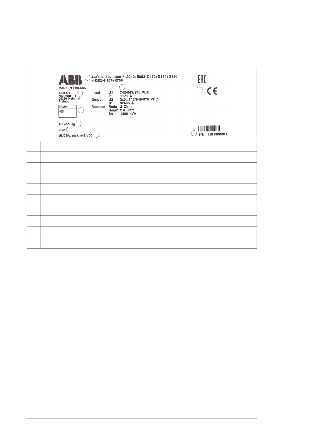
■ Brake unit type designation label
An example label of the brake unit is shown below.
Type designation.1
Manufacturer’s address.2
Frame size.3
Cooling method.4
Degree of protection.5
Maximum input voltage (UL/CSA).6
Ratings.7
Valid markings.8
Serial number. The first digit refers to the manufacturing plant. The next four digits indicate manufacturing
9
year and week respectively (yyww). The remaining digits complete the serial number so that there are
no two units with the same number.
■ Brake chopper module type designation label
Each module has a type designation label attached to it. The type designation stated on
the label contains information on the specifications and configuration of the module. The
first digits express the basic construction, for example “ACS880-104-0100A-3”. Any optional
selections are given thereafter, separated by plus signs.
Examples of the label are shown below.

Operation principle and hardware description 25
Type designation.1
Frame size.2
Degree of protection; additional UL/CSA specifications.3
Ratings. The labels show ratings for inverter module (INVERTER), IGBT supply module (LINE CONVERT-
4
ER), brake chopper module (BRAKE CHOPPER), regenerative rectifier module (REGENERATIVE
RECTIFIER) and DC/DC converter module (DC/DC CONVERTER).
Valid markings.5
Serial number. The first digit refers to the manufacturing plant. The next four digits indicate manufacturing
6
year and week respectively (yyww). The remaining digits complete the serial number so that there are
no two units with the same number.
Brake unit type designation key
Type designation describes the composition of the unit in short. The complete designation
code is divided in subcodes:
• The first digits form the basic code. It describes the basic construction of the unit. The
fields in the basic code are separated by hyphens.
• The plus codes follow the basic code. Each plus code starts with an identifying letter
(common for the whole product series), followed by descriptive digits. The plus codes
are separated by plus signs.
The subcodes are described below.
DESCRIPTIONCODE
Basic codes
Product seriesACS880
607
Ratings / size
Brake unit: Supply frequency 50 Hz, control (auxiliary) voltage 230 V AC, IEC industrial cabinet
construction, degree of protection IP22 (UL Type 1), cabling through bottom of cabinet, speedcontrolled module cooling fans, European-style cable entries, aluminum DC busbars (up to
3200 A), tin-plated copper DC busbars (from 3200 A up), DC fuses, ACS880 brake control
program, coated circuit boards, USB memory stick containing complete documentation in
English.
Sizexxxxx

26 Operation principle and hardware description
DESCRIPTIONCODE
Voltage range
3
513…566 V DC. This is indicated in the type designation label as typical input voltage level
566 V DC.
5
513…707 V DC. This is indicated in the type designation label as typical input voltage levels
566 / 679 / 707 V DC.
7
709…976 V DC. This is indicated in the type designation label as typical input voltage levels
742 / 849 / 976 (849 UL, CSA) V DC.
Option codes (plus codes)
Supply frequency
50 HzA012
60 HzA013
Degree of protection
IP22 (UL type 1)B053
IP42 (UL Type 1)B054
IP54 (UL Type 12)B055
Construction
Marine constructionC121
Cooling air through bottomC128
C129
UL approved
Channeled air outletC130
CSA approvedC134
Plinth height 100 mmC164
Plinth height 200 mmC179
Seismic designC180
Direct-on-line cooling fanC188
Resistor braking
Brake chopperD150
Brake resistorsD151
Filters
E210
EMC filter for second environment TN and IT (grounded and ungrounded) systems, category
C3.
Switchgear
DC switch/disconnectorF286
Heaters lights and auxiliary control voltage
Cabinet heater (external supply)G300
Cabinet lightingG301

Materials
Cabling
Operation principle and hardware description 27
DESCRIPTIONCODE
115 V control voltage for relaysG304
DC busbar material aluminumG314
DC busbar material tin plated copperG315
230 V AC control transformerG320
Halogen-free wiring and materialsG330
Brake resistor cables through the bottom of the cabinetH352
Brake resistor cables through the roof of the cabinetH353
Blind 3 mm steel cable gland platesH358
Blind 3 mm aluminum cable gland platesH364
Blind 6 mm brass cable gland platesH365
Control cables through the bottom of the cabinetH367
Control cables through the roof of the cabinetH368
Control panel and PC options
Control panel (max. 4 per door)J400
Drive monitoring displayJ401
Control panel mounting platform (max. 4 per door)J410
Common control panelJ412
I/O extension and feedback interface modules
FIO-11 analog I/O extension moduleL500
FIO-01 digital I/O extension moduleL501
RDCO-04 DDCS communication moduleL509
FAIO-01 analog I/O extension moduleL525
FDIO-01 digital I/O extension moduleL526
Ring topology for fiber optic link without NDCU-95 DDCS branching unitZ2016
Fieldbus adapter modules
Panel bus selectedK450
FDNA-01 DeviceNet™ adapter moduleK451
FPBA-01 PROFIBUS DP adapter moduleK454
FCAN-01 CANopen adapter moduleK457
FSCA-01 Modbus/RTU adapter moduleK458
FCNA-01 ControlNet™ adapter moduleK462
FECA-01 EtherCAT adapter moduleK469
Loading...