


 Loading...
—
ABB ME A SUREMENT & ANALY TICS | OPER ATING INSTRUCTION | OI/AV12 RE V. E
AV1 and AV2
Characterizable pneumatic and electro-pneumatic positioners
Pneumatic and electro-pneumatic positioners built on proven performance for demanding process conditions
Measurement made easy
—
Characterizable analog positioners
Introduction
AV characterizable pneumatic positioners are control devices that satisfy a wide range of applications. They provide fast, sensitive and accurate positioning of pneumatic singleor double-acting, linear or rotary motion actuators. A mechanical connection from the actuator to a position feedback cam in the positioner establishes actual position. Three characterized segments on one cam provide application flexibility by establishing various relationships between input signal and actuator position. The relationships provided by the segments are square root, linear and square.

Trademarks and Registrations
Registrations and trademarks used in this document include:
® Delrin |
Registered trademark of E.I. DuPont de Nemours Company, Incorporated |
® Dow Corning |
Registered trademark of Dow Corning Corporation |
® Lexan |
Registered trademark of General Electric Company, GE Plastics Division |
® Monel |
Registered trademark of International Nickel Company |
® Noryl |
Registered trademark of General Electric Company, GE Plastics Division |
® PowerRac |
Registered trademark of DeZurik, a Unit of General Signal |
® Rynite |
Registered trademark of E.I. DuPont de Nemours Company, Incorporated |
® Teflon |
Registered trademark of E.I. DuPont de Nemours Company, Incorporated |
® Valox |
Registered trademark of General Electric Company, GE Plastics Division |
® Viton |
Registered trademark of E.I. DuPont de Nemours Company, Incorporated |
WARNING notices as used in this manual apply to hazards or unsafe practices which could result in personal injury or death.
CAUTION notices apply to hazards or unsafe practices which could result in property damage.
NOTES highlight procedures and contain information which assist the operator in understanding the information contained in this manual.
All software, including design, appearance, algorithms and source codes, is copyrighted by ABB Inc. and is owned by ABB Inc. or its suppliers.
WARNING
POSSIBLE PROCESS UPSETS. Maintenance must be performed only by qualified personnel and only after securing equipment controlled by this product. Adjusting or removing this product while it is in the system may upset the process being controlled. Some process upsets may cause injury or damage.
NOTICE
The information contained in this document is subject to change without notice.
ABB Inc., its affiliates, employees, and agents, and the authors of and contributors to this publication specifically disclaim all liabilities and warranties, express and implied (including warranties of merchantability and fitness for a particular purpose), for the accuracy, currency, completeness, and/or reliability of the information contained herein and/or for the fitness for any particular use and/or for the performance of any material and/or equipment selected in whole or part with the user of/or in reliance upon information contained herein. Selection of materials and/or equipment is at the sole risk of the user of this publication.
This document contains proprietary information of ABB Inc., and is issued in strict confidence. Its use, or reproduction for use, for the reverse engineering, development or manufacture of hardware or software described herein is prohibited. No part of this document may be photocopied or reproduced without the prior written consent of ABB Inc..
Copyright 2019 ABB Inc. [May, 2019]

|
Table of Contents |
|||
|
Page |
|||
SECTION 1 - INTRODUCTION................................................................................................... |
1-1 |
|
|
|
OVERVIEW ..................................................................................................................................... |
1-1 |
|
||
INTENDED USER ........................................................................................................................... |
1-1 |
|
|
|
DESCRIPTION ................................................................................................................................ |
1-1 |
|
|
|
Performance Series Option ...................................................................................................... |
1-2 |
|
|
|
Explosionproof I/P Option......................................................................................................... |
1-3 |
|
|
|
NEMA 4X Option ...................................................................................................................... |
1-3 |
|
|
|
APPLICATION................................................................................................................................. |
1-3 |
|
|
|
FEATURES ..................................................................................................................................... |
1-3 |
|
||
INSTRUCTION CONTENT.............................................................................................................. |
1-5 |
|
|
|
REFERENCE DOCUMENTS .......................................................................................................... |
1-6 |
|
|
|
NOMENCLATURE .......................................................................................................................... |
1-6 |
|
|
|
SPECIFICATIONS........................................................................................................................... |
1-7 |
|
|
|
|
|
|
||
SECTION 2 - DESCRIPTION AND OPERATION....................................................................... |
2-1 |
|
|
|
INTRODUCTION ............................................................................................................................. |
2-1 |
|
|
|
FUNCTIONAL OPERATION ........................................................................................................... |
2-2 |
|
|
|
|
|
|
||
SECTION 3 - INSTALLATION .................................................................................................... |
3-1 |
|
|
|
INTRODUCTION ............................................................................................................................. |
3-1 |
|
|
|
UNPACKING AND INSPECTION.................................................................................................... |
3-1 |
|||
ENCLOSURE CLASSIFICATION.................................................................................................... |
3-2 |
|||
MOUNTING CONSIDERATIONS.................................................................................................... |
3-2 |
|||
MOUNTING TYPE AV POSITIONERS ........................................................................................... |
3-4 |
|||
TUBING CONNECTIONS ............................................................................................................... |
3-8 |
|
|
|
Air Supply Pressure.................................................................................................................. |
3-8 |
|
|
|
Air Supply Filtering ................................................................................................................... |
3-8 |
|
|
|
Air Supply Quality (Recommended) ......................................................................................... |
3-9 |
|||
Tubing Connections ................................................................................................................. |
3-9 |
|
|
|
WIRING TYPE AV2 POSITIONER................................................................................................ |
3-10 |
|||
WIRING TYPE AV1 POSITIONER................................................................................................ |
3-13 |
|||
RADIO FREQUENCY INTERFERENCE....................................................................................... |
3-15 |
|||
WIRING REQUIREMENTS ........................................................................................................... |
3-15 |
|
|
|
|
|
|
|
|
SECTION 4 - CALIBRATION...................................................................................................... |
4-1 |
|
|
|
INTRODUCTION ............................................................................................................................. |
4-1 |
|
|
|
CALIBRATION................................................................................................................................. |
4-1 |
|
|
|
Zero Adjustment ....................................................................................................................... |
4-1 |
|
|
|
Span Adjustment ...................................................................................................................... |
4-3 |
|
|
|
CALIBRATION FOR PARTICULAR APPLICATION ....................................................................... |
4-3 |
|||
Zero Adjustment ....................................................................................................................... |
4-4 |
|
|
|
Span Adjustment ...................................................................................................................... |
4-4 |
|
|
|
GAIN AND SPEED ADJUSTMENTS .............................................................................................. |
4-5 |
|||
Gain Adjustment....................................................................................................................... |
4-5 |
|
|
|
Speed Adjustment .................................................................................................................... |
4-6 |
|
|
|
ORIFICE............................................................................................................................ |
4-6 |
|
|
|
PILOT VALVE STROKE ADJUSTMENT .......................................................................... |
4-6 |
|||
TROUBLESHOOTING CALIBRATION ADJUSTMENTS................................................................ |
4-8 |
|
||
|
|
|||
SECTION 5 - OPERATING PROCEDURES............................................................................... |
5-1 |
|
||
INTRODUCTION ............................................................................................................................. |
5-1 |
|
|
|
i

Table of Contents (continued)
EQUALIZING AND AIR SUPPLY SHUTOFF VALVE |
Page |
..................................................................... 5-1 |
|
Transfer from Automatic to Manual Operation ........................................................................ |
5-1 |
Transfer from Manual to Automatic Operation ........................................................................ |
5-1 |
...........................................................................................SECTION 6 - TROUBLESHOOTING |
6-1 |
|||
INTRODUCTION ............................................................................................................................ |
6-1 |
|
|
|
|
|
|
|
|
SECTION 7 - MAINTENANCE..................................................................................................... |
7-1 |
|
|
|
INTRODUCTION ............................................................................................................................ |
7-1 |
|
|
|
PREVENTIVE MAINTENANCE SCHEDULE ................................................................................. |
7-1 |
|||
PREVENTIVE MAINTENANCE PROCEDURES ........................................................................... |
7-2 |
|
||
MANIFOLD FILTERS ..................................................................................................................... |
7-2 |
|
|
|
|
|
|
||
SECTION 8 - REPAIR AND REPLACEMENT............................................................................. |
8-1 |
|
|
|
INTRODUCTION ............................................................................................................................ |
8-1 |
|
|
|
REPLACEMENT PROCEDURES .................................................................................................. |
8-1 |
|||
Manifold................................................................................................................................... |
8-1 |
|
|
|
Gain Hinge Spring ................................................................................................................... |
8-2 |
|
|
|
Pilot Valve Assembly ............................................................................................................... |
8-3 |
|
|
|
I/P Converter ........................................................................................................................... |
8-4 |
|
|
|
Cam......................................................................................................................................... |
8-5 |
|
|
|
Diaphragm Assembly .............................................................................................................. |
8-5 |
|
|
|
DIAPHRAGM ASSEMBLY REMOVAL............................................................................. |
8-6 |
|||
DIAPHRAGM ASSEMBLY REPLACEMENT ................................................................... |
8-6 |
|
||
PILOT VALVE STROKE ADJUSTMENT........................................................................................ |
8-7 |
|||
|
|
|
||
SECTION 9 - SUPPORT SERVICES........................................................................................... |
9-1 |
|||
INTRODUCTION ............................................................................................................................ |
9-1 |
|
|
|
RECOMMENDED SPARE PARTS................................................................................................. |
9-1 |
|||
ADDITIONAL SPARE PARTS ........................................................................................................ |
9-3 |
|
|
|
|
|
|
||
APPENDIX A - POSITION TRANSMITTERS ............................................................................. |
A-1 |
|
|
|
INTRODUCTION ............................................................................................................................ |
A-1 |
|||
DESCRIPTION AND OPERATION ................................................................................................ |
A-1 |
|||
CALIBRATION................................................................................................................................ |
A-2 |
|||
Calibrating the Potentiometric Position Transmitter ................................................................ |
A-2 |
|||
POTENTIOMETRIC APPLICATION EXAMPLE .............................................................. |
A-3 |
|||
CALIBRATING THE POTENTIOMETRIC EXAMPLE ...................................................... |
A-4 |
|||
Calibrating the 4 to 20-mA Position Transmitter...................................................................... |
A-6 |
|||
|
|
|||
APPENDIX B - QUICK START................................................................................................... |
B-1 |
|
||
INTRODUCTION ............................................................................................................................ |
B-1 |
|||
PRODUCT IDENTIFICATION (NOMENCLATURE)....................................................................... |
B-1 |
|||
MOUNTING THE POSITIONER..................................................................................................... |
B-2 |
|||
TUBING CONNECTIONS............................................................................................................... |
B-5 |
|||
TYPE AV2 POSITIONER WIRING ................................................................................................. |
B-8 |
|||
TYPE AV1 POSITIONER WIRING ............................................................................................... |
B-10 |
|||
CALIBRATION.............................................................................................................................. |
B-11 |
|||
ii

Table of Contents (continued) |
|||
|
Page |
||
APPENDIX C - CAM CHARACTERIZATION ............................................................................. |
C-1 |
|
|
INTRODUCTION ............................................................................................................................ |
C-1 |
||
CAM CHARACTERIZATION .......................................................................................................... |
C-1 |
||
CAM SELECTION .......................................................................................................................... |
C-3 |
||
CAM SHAPING .............................................................................................................................. |
C-5 |
||
|
|
|
|
APPENDIX D - TYPE AV1 PNEUMATIC POSITION TRANSMITTER....................................... |
D-1 |
|
|
INTRODUCTION ............................................................................................................................ |
D-1 |
||
DESCRIPTION ............................................................................................................................... |
D-1 |
||
INSTALLATION .............................................................................................................................. |
D-2 |
||
CALIBRATION................................................................................................................................ |
D-3 |
||
|
|
|
|
List of Figures
No. |
Title |
Page |
1-1. |
Capacity (Exhaust to Atmosphere)........................................................................................... |
1-9 |
1-2. |
Air Consumption ..................................................................................................................... |
1-10 |
1-3. |
Output Air Flow vs. Error Signal — Standard and Performance Series ................................. |
1-10 |
1-4. |
Expanded First Quadrant View .............................................................................................. |
1-11 |
2-1. |
Operation Diagram ................................................................................................................... |
2-1 |
2-2. |
Block Diagram .......................................................................................................................... |
2-1 |
3-1. |
External and Mounting Dimensions.......................................................................................... |
3-3 |
3-2. |
Electrical Connections.............................................................................................................. |
3-4 |
3-3. |
Drive Arm Connections............................................................................................................. |
3-4 |
3-4. |
Drive Shaft Variations............................................................................................................... |
3-5 |
3-5. |
Mounting Using Linkage (Typical) ............................................................................................ |
3-5 |
3-6. |
Mounting Using Direct Coupling (Typical) ................................................................................ |
3-6 |
3-7. |
Cam.......................................................................................................................................... |
3-7 |
3-8. |
Cam Roller Alignment............................................................................................................... |
3-8 |
3-9. |
Port Locations .......................................................................................................................... |
3-9 |
3-10. |
Direct Acting, Top Loaded, Single Acting Tubing Example..................................................... |
3-11 |
3-11. |
Reverse Acting, Top Loaded, Single Acting Tubing Example................................................. |
3-12 |
3-12. |
Direct Acting, Bottom Loaded, Single Acting Tubing Example ............................................... |
3-12 |
3-13. |
Reverse Acting, Bottom Loaded, Single Acting Tubing Example ........................................... |
3-13 |
3-14. |
Double Acting Tubing Example .............................................................................................. |
3-14 |
3-15. |
Wiring Connections ................................................................................................................ |
3-14 |
4-1. |
Calibration Adjustments............................................................................................................ |
4-2 |
4-2. |
Cam Roller Alignment............................................................................................................... |
4-3 |
4-3. |
Zero Adjustment Graph ............................................................................................................ |
4-4 |
4-4. |
Span Adjustment Graph ........................................................................................................... |
4-5 |
4-5. |
Pilot Valve Adjustment.............................................................................................................. |
4-7 |
4-6. |
Speed Adjustment Screws ....................................................................................................... |
4-7 |
4-7. |
I/P Adjustment .......................................................................................................................... |
4-9 |
7-1. |
Positioner with Manifold ........................................................................................................... |
7-3 |
7-2. |
Manifold with Filter Cover Removed ........................................................................................ |
7-3 |
8-1. |
Positioner with Manifold ........................................................................................................... |
8-2 |
8-2. |
Manifold O-Rings...................................................................................................................... |
8-3 |
iii

List of Figures (continued)
No. |
Title |
Page |
8-3. |
Pilot Valve Measurement for Maximum Speed........................................................................ |
8-8 |
8-4. |
Stroke Adjustment Screws....................................................................................................... |
8-8 |
9-1. |
Mounting Kits........................................................................................................................... |
9-6 |
9-2. |
Bypass Valve Assembly........................................................................................................... |
9-8 |
9-3. |
Type AV1 Positioner ............................................................................................................... |
9-11 |
9-4. |
Type AV2 Positioner (Page 1 of 2)......................................................................................... |
9-16 |
9-4. |
Type AV2 Positioner (Page 2 of 2)......................................................................................... |
9-17 |
A-1. |
Terminal Block Connections .................................................................................................... |
A-2 |
A-2. |
Schematic Diagram ................................................................................................................. |
A-4 |
A-3. |
Potentiometric Position Transmitter (Exploded View).............................................................. |
A-5 |
A-4. |
Calibration Features for 4 to 20-mA Position Transmitter........................................................ |
A-6 |
A-5. |
4 to 20-mA Position Transmitter (Exploded View) ................................................................... |
A-7 |
B-1. |
Mounting Using Linkage (Typical) ........................................................................................... |
B-3 |
B-2. |
Mounting Using Direct Coupling (Typical) ............................................................................... |
B-3 |
B-3. |
Drive Arm Connections............................................................................................................ |
B-4 |
B-4. |
Cam Roller Alignment.............................................................................................................. |
B-4 |
B-5. |
Port Locations.......................................................................................................................... |
B-5 |
B-6. |
Direct Acting, Top Loaded, Single Acting Tubing Example ...................................................... |
B-6 |
B-7. |
Reverse Acting, Top Loaded, Single Acting Tubing Example .................................................. |
B-6 |
B-8. |
Direct Acting, Bottom Loaded, Single Acting Tubing Example ................................................ |
B-7 |
B-9. |
Reverse Acting, Bottom Loaded, Single Acting Tubing Example ............................................ |
B-7 |
B-10. |
Double Acting Tubing Example................................................................................................ |
B-8 |
B-11. |
Wiring Connections ................................................................................................................. |
B-9 |
B-12. |
Calibration Adjustments........................................................................................................... |
B-9 |
C-1. |
Cam A, Square Root Relationship........................................................................................... |
C-1 |
C-2. |
Cam B, Linear Relationship..................................................................................................... |
C-2 |
C-3. |
Cam C, Square Relationship................................................................................................... |
C-2 |
C-4. |
Regulated Device Characteristics ........................................................................................... |
C-4 |
C-5. |
Desired Control........................................................................................................................ |
C-4 |
C-6. |
Cam Characteristics ................................................................................................................ |
C-5 |
C-7. |
Graph to Cam Data Transfer ................................................................................................... |
C-7 |
D-1. |
Pneumatic Position Transmitter Kit.......................................................................................... |
D-2 |
|
|
|
List of Tables
No. |
Title |
Page |
1-1. |
Reference Documents............................................................................................................. |
1-6 |
1-2. |
Nomenclature .......................................................................................................................... |
1-6 |
1-3. |
Type AV1/2 Positioner Specifications...................................................................................... |
1-7 |
1-4. |
Type AV ____1__ Potentiometric Position Transmitter Specifications .................................. |
1-11 |
1-5. |
Type AV____2__ 4 to 20-mA Position Transmitter Specifications ....................................... |
1-11 |
1-6. |
Agency Approvals.................................................................................................................. |
1-12 |
1-7. |
Accessories ........................................................................................................................... |
1-12 |
1-8. |
Rotary Actuator Retrofit Mounting Kits .................................................................................. |
1-13 |
1-9. |
Speed Control Orifices .......................................................................................................... |
1-13 |
1-10. |
Pressure Gages..................................................................................................................... |
1-13 |
1-11. |
Supply Air Regulators with Gages......................................................................................... |
1-13 |
iv

|
List of Tables (continued) |
|
No. |
Title |
Page |
1-12. |
Supply Air Filters .................................................................................................................... |
1-14 |
1-13. |
Component Material List ........................................................................................................ |
1-14 |
3-1. |
Cam Characteristics ................................................................................................................. |
3-7 |
4-1. |
Gain Hinge Springs .................................................................................................................. |
4-5 |
6-1. |
Positioner Errors....................................................................................................................... |
6-1 |
7-1. |
Preventive Maintenance Schedule........................................................................................... |
7-1 |
9-1. |
Shutoff Valve Kit No. 258270_1 ............................................................................................... |
9-1 |
9-2. |
AV Diaphragm Assembly Kit No. 258486_1............................................................................. |
9-1 |
9-3. |
AV Diaphragm Assembly Kit No. 258486_2 ............................................................................ |
9-2 |
9-4. |
Filter Replacement Kit No. 258487_1 ...................................................................................... |
9-2 |
9-5. |
Pilot Valve Assembly Kit No. 258488_1 ................................................................................... |
9-2 |
9-6. |
Pilot Valve Assembly Kit No. 258488_2................................................................................... |
9-2 |
9-7. |
Pilot Valve Assembly Kit No. 258488_3 ................................................................................... |
9-2 |
9-8. |
Pilot Valve Assembly Kit No. 258488_4................................................................................... |
9-3 |
9-9. |
Cam.......................................................................................................................................... |
9-3 |
9-10. |
I/P Assembly Kit No. 258477_1................................................................................................ |
9-3 |
9-11. |
Gain Hinge Springs .................................................................................................................. |
9-3 |
9-12. |
Manifold Assembly Kit No. 258491_1 ...................................................................................... |
9-3 |
9-13. |
Cam Follower Arm Kit No. 258544_1 ...................................................................................... |
9-4 |
9-14. |
Cover Assembly Kit No. 258545_1 .......................................................................................... |
9-4 |
9-15. |
Cover Assembly Kit No. 258545_1 .......................................................................................... |
9-4 |
9-16. |
Gage Block Assembly Kit No. 258569_1 ................................................................................. |
9-4 |
9-17. |
Gage Block Assembly Kit No. 258569_3 ................................................................................. |
9-4 |
9-18. |
Potentiometer ........................................................................................................................... |
9-4 |
9-19. |
4 to 20-mA Position Transmitter Circuit Board ......................................................................... |
9-5 |
9-20. |
Positioner Mounting Kit Number 5327321_121........................................................................ |
9-5 |
9-21. |
Positioner Mounting Kit Number 5327321_131........................................................................ |
9-5 |
9-22. |
Positioner Mounting Kit Number 5327321_141 (for use on Fisher Actuators) ......................... |
9-6 |
9-23. |
Rotary Actuator Retrofit Mounting Kits ..................................................................................... |
9-7 |
9-24. |
Bypass Valve Assembly (Optional) .......................................................................................... |
9-7 |
9-25. |
Type AV1 Positioner Parts List................................................................................................. |
9-9 |
9-26. |
Input Signal Parts Reference for Type AV1 Positioners......................................................... |
9-10 |
9-27. |
Cam Selection and Manifold/Gage Block Parts Reference |
|
|
for Type AV1 Positioners........................................................................................................ |
9-10 |
9-28. |
Shaft Position Transmitter Parts Reference for Type AV1 Positioners .................................. |
9-12 |
9-29. |
Drive Shaft Parts Reference for Type AV1 Positioners.......................................................... |
9-12 |
9-30. |
Type AV2 Positioner Parts List .............................................................................................. |
9-12 |
9-31. |
Cam and Drive Shaft Parts Reference for Type AV2 Positioners .......................................... |
9-13 |
9-32. |
Manifold/Gage Block Parts Reference for Type AV2 Positioners .......................................... |
9-15 |
9-33. |
Shaft Position Transmitter Parts Reference for Type AV2 Positioners .................................. |
9-15 |
9-34. |
Conversion Kits ...................................................................................................................... |
9-17 |
A-1. |
Potentiometric Position Transmitter Parts List ........................................................................ |
A-5 |
A-2. |
4 to 20-mA Position Transmitter Parts List.............................................................................. |
A-7 |
B-1. |
Nomenclature .......................................................................................................................... |
B-1 |
B-2. |
Calibration Procedures.......................................................................................................... |
B-11 |
C-1. |
Control Signal Pressure Conversions (AV1) ........................................................................... |
C-3 |
C-2. |
Input to Output I/P Converter Relationships (AV2).................................................................. |
C-3 |
D-1. |
Pneumatic Position Transmitter Kit (258492_1)...................................................................... |
D-2 |
v

Read First
WARNING
INSTRUCTION MANUALS
Do not install, maintain or operate this equipment without reading, understanding and following the proper factory-supplied instructions and manuals, otherwise injury or damage may result.
RETURN OF EQUIPMENT
All equipment being returned to the factory for repair must be free of any hazardous materials (acids, alkalis, solvents, etc.). A Material Safety Data Sheet (MSDS) for all process liquids must accompany returned equipment.
Contact the factory for authorization prior to returning equipment.
Read these instructions before starting installation; save these instructions for future reference.
Contacting the Factory . . .
Should assistance be required with any of the company’s products, contact the following:
Telephone:
24-Hour Call Center
1-800-HELP-365
E-Mail:
ins.techsupport@us.abb.com
Read First I

Read First II

SECTION 1 - INTRODUCTION
OVERVIEW
This section covers the following topics:
•
•
•
•
•
•
•
•
•
•
•
Positioner description.
Positioner application.
Features of positioners.
Instruction content.
How to use this instruction.
Positioner nomenclature.
Positioner specifications.
Position transmitter specifications.
Agency approvals.
Accessories.
Mounting kits.
NOTE: Appendix B provides a quick start guide for the Type AV positioner. It is intended for control engineers having experience in the use and application of pneumatic positioners. The quick start guide highlights the major points of installation and calibration. Detailed installation and calibration information is contained in Section 3 and Section 4 respectively.
INTENDED USER
The information in this instruction is a guide for technical personnel responsible for installation, calibration, operation, maintenance and repair of the positioner.
DESCRIPTION
The Type AV1 and Type AV2 positioners are control devices that satisfy a wide range of applications. They provide fast, sensitive and accurate positioning of pneumatic single or double acting actuators.
The Type AV1 positioner receives an external pneumatic signal and converts it to a pneumatic output. The Type AV2 positioner accepts a four to 20-milliamp current that is applied to an I/P (current to pneumatic) converter, located inside the housing, to generate an internal signal pressure.
If a loss of signal occurs, the Type AV2 positioner goes to the four-milliamp position. The Type AV1 positioner goes to the 3 psi position.
OVERVIEW
1 - 1
INTRODUCTION
A mechanical connection from the actuator (i.e., cylinder, valve, etc.) to the position feedback cam in the positioner establishes actual position. Three characterized segments on the cam provide application flexibility by establishing various relationships between the input signal and the actuator position. The characterized curves on the cam provide:
•
•
•
Square root relationship. Linear relationship. Square characteristic.
Using the zero, span and gain adjustments and the cam, the actuator can respond with characteristics specific to an application.
An optional manifold assembly provides an integral shutoff and equalizing valve that can be used to isolate the positioner from an actuator, allowing manual override without removing the positioner from the process (required on double acting actuators with manual override). The manifold also provides gage ports and disposable filter cartridges that insure fast servicing and minimum downtime.
An optional gage block provides gage ports for mounting pressure gages. There are three gage ports on the block: One for instrument indication (internal input signal) and two for output indication. The gage block does not provide filters or means of isolating the positioner from the actuator. Installation of a supply gage is possible in the supply line (piping by customer).
Both positioners can be equipped with either an optional potentiometric or a four to 20-milliamp position transmitter that provides additional control features.
Performance Series Option
The Type AV positioner performance series provides a high flow gain pilot valve body by adding a P in the ninth nomenclature position. This high gain pilot valve body has square ports that provide a maximized air flow for a small motion of the pilot valve stem. A relatively small error signal can therefore cause a relatively large change in output air flow to the actuator. This feature is useful when driving larger actuators that might otherwise be insensitive or slow to respond to small signal changes.
Compared to other positioners on the market, the standard Type AV positioners have a high delivery capacity. The performance series increases this delivery capacity even more. The flow gain curves shown in Figures 1-3 and 1-4 show output air flow versus input error signal for the standard and high gain performance series positioners.
DESCRIPTION
1 - 2

INTRODUCTION
Figures 1-3 and 1-4 show that the large signal maximum air flow for both the standard and performance series positioners is about the same. The performance series positioners achieve maximum flow capacity at a much smaller error signal.
NOTE: ABB does not recommend using a performance series positioner on a small actuator, as it could cause instability.
Explosionproof I/P Option
The Type AV27 positioner employs an explosionproof I/P converter that is mounted to an adapter block manifold. The adapter block manifold is bolted to the outside of the main positioner housing. The unit is a Type AV12 positioner with the electric to pneumatic (four to 20-milliamp to 20.7 to 103.4-kilopascal (3.0 to 15.0-pounds per square inch gage)) conversion occurring within the externally mounted I/P converter.
The four to 20-milliamp input signal wires shall be connected through an explosionproof conduit entrance on the I/P converter. If no electrical connections are made within the main housing, the entire positioner can be considered suitable for application in the hazardous locations shown on the I/P label.
Refer to Figure 3-1 for the external and mounting dimensions of the Type AV27 positioner.
NEMA 4X Option
The Type AV______N positioner comes with a NEMA 4X housing. To maintain the NEMA 4X classification, the positioner shall be installed per drawing C258567 and suitable piping shall be attached to the vent opening and vented in a manner to preclude the entrance of water under pressure, as from a hose. Additionally, the conduit connections shall be suitable for a NEMA 4X rating.
APPLICATION
The Type AV1 and Type AV2 Characterizable Pneumatic Positioners control the position of a pneumatic actuator.
FEATURES
•Trouble-Free Operation. Proven pilot valve that is quickly removable, provides less downtime, lower maintenance costs, increased reliability and extended performance.
•Compact Rugged Design. Die cast aluminum housing, beam, spring arm, follower arm and 303 stainless steel pilot
APPLICATION
1 - 3

INTRODUCTION
valve provide long life and maximum environmental protection. The compact housing increases mounting flexibility.
•Characterizable Output. Large positioning cam can be shaped to provide desired relationship between the input signal and the actuator position.
•Accurate Calibration. Independent zero and span adjustments eliminate interaction and provide fast and accurate calibration.
•Simplified Reverse Operation. Action can be changed in the field by changing cams and reversing 01 and 02 connections. The reverse acting cam is conveniently located on the inside of the front cover.
•
•
•
Highly Visible Position Status Indicator. A fluorescent orange position indicator is visible through a polycarbonate window, providing fast indication of actuator position.
Vent Design Allows Natural Gas Operation. Vent pipe arrangement permits operation using natural gas.
Split Range Service. Split range capability allows sequencing of multiple actuators using a single control signal.
•Adjustable Gain. Two levels of gain are possible by changing the hinge springs supplied with the positioner.
•Adaptable Usage. The positioner can control both single and double acting, linear and rotary type actuators.
•
•
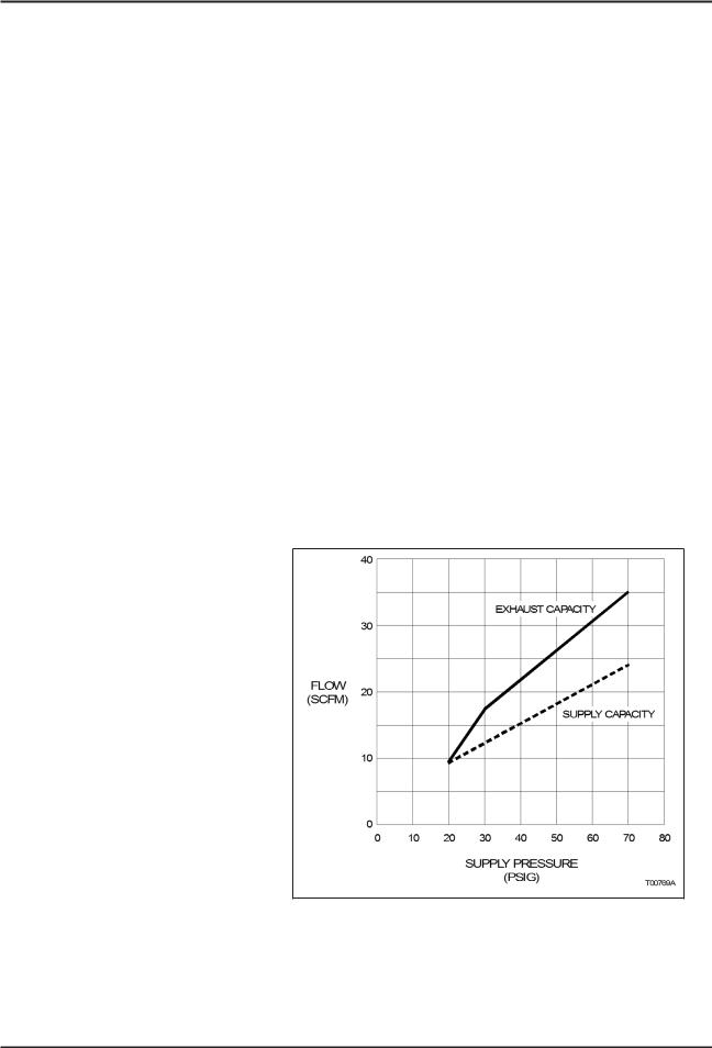
High Capacity. More than 0.65 cubic meters per minute (23 standard cubic feet per minute) can be supplied or exhausted at 482.6 kilopascals (70.0 pounds per square inch gage) supply pressure (Fig. 1-1).
Continuously Adjustable Span and Zero for Each Stroke Level. Capable of 100-percent stroke for 50-percent signal span or 50-percent stroke for 100-percent signal span.
•Low Air Consumption. Enhanced pilot valve design and manufacturing technique allows the Type AV positioner maximum performance with minimum air consumption (Fig. 1-2).
•Adjustable Speed Control without Additional Hardware. Speed of actuator can be reduced to desired speed using the pilot valve stroke adjustment screws.
FEATURES
1 - 4

INTRODUCTION
INSTRUCTION CONTENT
|
This instruction includes the following sections: |
|
Introduction |
Provides a description of this instruction; its sections and uses, |
|
|
along with a brief description of the Type AV1 and Type AV2 posi- |
|
|
tioners. This section also provides reference documents (Table |
|
|
1-2), product nomenclature (Table 1-2), specifications (Tables 1-3, |
|
|
1-4 and 1-5), agency approvals (Table 1-6) and positioner acces- |
|
|
sories (Table 1-7). Table 1-8 lists retrofit mounting kits, Table 1-9 |
|
|
lists available speed control orifices, and Table 1-10 lists the avail- |
|
|
able pressure gages. Table 1-11 lists pressure regulators, Table |
|
|
1-12 lists supply air filters available from ABB and Table 1-13 lists |
|
|
the materials used in the positioner components. |
|
Description and |
Describes the functional operation of the positioners. |
|
Operation |
|
|
Installation |
Provides information about installing a Type AV positioner. |
|
Calibration |
Provides calibration and adjustment procedures. |
|
Operating Procedures |
Presents information and procedures for various applications. |
|
Troubleshooting |
Provides a table containing errors, causes and corrective action. |
|
Maintenance |
Includes preventive maintenance information and procedures. |
|
Repair and |
Procedures in this section give step-by-step instructions for |
|
Replacement |
removing and replacing components. |
|
Support Services |
Provides recommended spare and replacement parts lists. Illus- |
|
|
trations of both positioners provide part numbers for all major |
|
|
components. |
|
Appendix A |
Provides calibration information about the four to 20-milliamp posi- |
|
|
tion transmitter and the potentiometric position transmitter. |
|
Appendix B |
Quick start section for control engineers that are knowledgeable |
|
|
about positioners and the overall process in which the positioner is |
|
|
to be used. |
|
Appendix C |
Details cam shaping information. |
|
Appendix D |
Covers the pneumatic position transmitter option. |
|
|
HOW TO USE THIS INSTRUCTION |
|
|
For safety reasons, read and completely understand this instruc- |
|
|
tion before completing any tasks or procedures associated with |
|
|
installation, calibration, operation, maintenance or repair. |
|
|
INSTRUCTION CONTENT |
|
|
1 - 5 |
|

INTRODUCTION
The section arrangement of this instruction is sequential. After initial start-up and calibration, store this instruction in a safe place for future reference.
REFERENCE DOCUMENTS
|
Table 1-1. Reference Documents |
|
|
Number |
Title |
ANSI/NFPA 70 |
National Electrical Code |
CEC |
Canadian Electrical Code |
D-AAP-UP |
Universal Pneumatic Rotary Actuator, Type UP (specification) |
D-APE-AV1234 |
Characterizable Positioners, Type AV1, AV2, AV3 & AV4 (specification) |
CSA c22.1 |
Process Control Equipment |
I-E96-500 |
Site Planning and Preparation |
I-P81-20 |
Universal Pneumatic Rotary Actuator, Type UP (instruction) |
ANSI/ISA-7.0.01-1996 |
Quality Standards for Instrument Air |
ISA S75.13-1989 |
Method of Evaluating the Performance of Positioners with Analog Input Signals and |
|
Pneumatic Output (Instrument Society of America) |
P-P88-001 |
Product Application Guide, Installing a Type AV Positioner in a Hazardous Location |
NOMENCLATURE
|
|
|
|
|
|
|
|
|
|
|
|
|
Table 1-2. Nomenclature |
|
|
|
|
|
|
|
|
|
|
|
|
|
|
Position |
1 |
2 |
3 |
4 |
5 |
6 |
7 |
8 |
9 |
|
|||
Type |
A V |
_ |
_ |
_ |
_ |
_ |
_ |
_ |
Characterizable Positioners |
||||
|
|
|
1 |
|
|
|
|
|
|
|
|
|
Characterizable Pneumatic Positioner |
|
|
|
|
|
Next Page |
||||||||
|
|
|
|
|
|
||||||||
|
|
|
2 |
|
|
|
|
|
|
|
|
|
Characterizable 4 to 20-mA Input Positioner (actuator moves to 0% |
|
|
|
|
|
|
|
|
|
|
|
|
|
|
|
|
|
|
|
|
|
|
|
|
|
|
|
or 100% upon loss of signal) |
|
|
|
|
|
|
|
|
|
|
|
|
|
Input Signal |
|
|
|
|
1 |
|
|
|
|
|
|
|
|
20.7 to 103.4 kPa (3.0 to 15.0 psig) (Type AV1) |
|
|
|
|
2 |
|
|
|
|
|
|
|
|
20.7 to 186.2 kPa (3.0 to 27.0 psig) (Type AV1) |
|
|
|
|
3 |
|
|
|
|
|
|
|
|
4 to 20 mA (standard intrinsically safe Type AV2) |
|
|
|
|
5 |
|
|
|
|
|
|
|
|
20.7 to 103.4 kPa (3.0 to 15.0 psig), high temperature applications |
|
|
|
|
|
|
|
|
|
|
|
|
|
(Type AV1) 1 |
|
|
|
|
6 |
|
|
|
|
|
|
|
|
20.7 to 186.2 kPa (3.0 to 27.0 psig), high temperature applications |
|
|
|
|
|
|
|
|
|
|
|
|
|
(Type AV1) 1 |
|
|
|
|
7 |
|
|
|
|
|
|
|
|
4 to 20 mA with explosionproof I/P converter (NEMA 7) (Type AV2) 2 |
|
|
|
|
|
|
|
|
|
|
|
|
|
Stroke/Rotary Motion (cam selection) |
|
|
|
|
|
1 |
|
|
|
|
|
|
|
12.7 to 50.8 mm (0.5 to 2.0 in.) or 45° rotary motion |
|
|
|
|
|
2 |
|
|
|
|
|
|
|
25.4 to 101.6 mm (1.0 to 4.0 in.) or 90° rotary motion |
REFERENCE DOCUMENTS
1 - 6

|
|
|
|
|
|
|
|
|
|
|
|
|
INTRODUCTION |
|
|
|
|
|
|
|
|
|
|
|
|
|
Table 1-2. Nomenclature (continued) |
|
|
|
|
|
|
|
|
|
|
|
|
|
|
|
Position |
1 |
2 |
3 |
4 |
5 |
6 |
7 |
8 |
9 |
|
|
|
|
Type |
A V |
_ |
_ |
_ |
_ |
_ |
_ |
_ |
Characterizable Positioners |
|||
|
|
|
|
|
|
|
|
|
|
|
|
Manifold (includes filters)/Gage Block |
|
|
|
|
|
|
|
Prev |
|
|
|
|
|
||
|
|
|
|
|
|
|
|
0 |
|
|
|
|
No manifold |
|
|
|
|
|
|
|
|
1 |
|
|
|
|
Manifold with equalizing valve, filters and gage ports (required for dou- |
|
|
|
|
|
|
|
|
|
|
|
|
|
ble acting actuators with manual override) |
|
|
|
|
|
|
|
|
2 |
|
|
|
|
Manifold with equalizing valve inoperable (includes filters and gage |
|
|
|
|
|
|
|
|
|
|
|
|
|
ports) 3 |
|
|
|
|
|
|
|
|
3 |
|
|
|
|
Gage block (gage port only) 1 |
|
|
|
|
|
|
|
|
|
|
|
|
|
Position Transmitter |
|
|
|
|
|
|
|
|
|
0 |
|
|
|
None (must be 0 for Types AV15, AV16 and AV27) |
|
|
|
|
|
|
|
|
|
1 |
|
|
|
Potentiometric resistive output |
|
|
|
|
|
|
|
|
|
2 |
|
|
|
4 to 20-mA output |
|
|
|
|
|
|
|
|
|
|
|
|
|
Drive Shaft |
|
|
|
|
|
|
|
|
|
|
0 |
|
|
Standard with feedback arm for linear motion |
|
|
|
|
|
|
|
|
|
|
1 |
|
|
0.500-in. square end |
|
|
|
|
|
|
|
|
|
|
2 |
|
|
0.342-in. square end for older DeZurik actuators |
|
|
|
|
|
|
|
|
|
|
3 |
|
|
0.250 in. across flats (UP1 and UP2 after August, 1995) |
|
|
|
|
|
|
|
|
|
|
4 |
|
|
0.375 in. square for DeZurik PowerRac® actuators |
|
|
|
|
|
|
|
|
|
|
5 |
|
|
0.156 in. across flats for NAMUR rotary actuators |
|
|
|
|
|
|
|
|
|
|
|
|
|
Other Options |
|
|
|
|
|
|
|
|
|
|
|
0 |
Standard (no other options) |
|
|
|
|
|
|
|
|
|
|
|
|
N |
NEMA 4X enclosure rating (when installed per drawing C258567) |
|
|
|
|
|
|
|
|
|
|
|
|
P |
Performance Series — high pneumatic gain for large actuators |
|
|
NOTES: |
|
|
|
|
|
|
|
|
|
|
|
|
1.High temperature Type AV1 positioners are only available without manifolds or position transmitters; however, gage blocks are permitted.
2.Explosionproof Type AV2 positioners are not available with position transmitters or manifolds
3.No longer available as of October 2003..
SPECIFICATIONS
Table 1-3 provides performance specifications of the Type AV1 and Type AV2 positioners. Tables 1-4 and 1-5 provide performance specifications for the position transmitters.
Table 1-3. |
Type AV1/2 Positioner Specifications1 |
|
Property |
|
Characteristic/Value |
Input range |
|
|
AV11 and AV15 |
|
20.7 to 103.4 kPa (3.0 to 15.0 psig) |
AV12 and AV16 |
|
20.7 to 186.2 kPa (3.0 to 27.0 psig) |
AV23 and AV27 |
|
4 to 20 mA |
Input impedance (Type AV2 only) |
|
|
Nominal |
|
215 at 22°C (72°F) |
Maximum |
|
245 at 60°C (140°F) |
SPECIFICATIONS
1 - 7

INTRODUCTION
Table 1-3. Type AV1/2 Positioner Specifications1 (continued)
Property |
Characteristic/Value |
Standard stroke range (cam selection) |
|
AV__1____ |
12.7 to 50.8 mm (0.5 to 2.0 in.) linear, rotary input 45° |
AV__2____ |
25.4 to 101.6 mm (1.0 to 4.0 in.) linear, rotary input 90° |
Gain |
2 adjustment levels by changing gain hinge spring. Refer to the flow |
|
gain curves as shown in Figures 1-3 and 1-4 for standard and high |
|
gain units. |
Accuracy2 |
|
AV1 |
0.80% of span maximum |
AV2 |
0.90% of span maximum |
Resolution |
|
AV1 |
0.09% of span maximum |
AV2 |
0.30% of span maximum |
Hysteresis2 |
|
AV1 |
0.45% of span maximum |
AV2 |
0.70% of span maximum |
Repeatability2 |
|
AV1 |
0.12% of span maximum |
AV2 |
0.50% of span maximum |
Deadband2 |
|
AV1 |
0.12% of span maximum |
AV2 |
0.30% of span maximum |
Linearity2 |
0.70% of span maximum |
Supply pressure |
172 to 1034 kPa (25 to 150 psig) |
|
NOTE: Minimum supply pressure should be 34.4 kPa (5.0 psig) above operating pres- |
|
sure required by actuator. |
Supply pressure effect |
0.05% per 6.9 kPa for ±69 kPa change |
|
(0.05% per 1.0 psi for ±10 psig change) |
Capacity (maximum capacity exhaust- |
Refer to Figure 1-1. |
ing to atmosphere) |
|
Air consumption |
Refer to Figure 1-2. |
Vibration effect2 |
<2.0% error for: |
|
5 to 15 Hz at peak-to-peak constant displacement of 4 mm (0.16 in.) |
|
15 to 120 Hz at accelerations to 2 Gs |
Pneumatic connections |
¼-NPT on supply, signal and output connections |
|
18 -NPT on pressure gages |
Materials of construction |
|
Enclosure |
Aluminum and <0.5% magnesium |
Pilot valve |
303 stainless steel |
Enclosure classification |
|
Standard |
NEMA 3R classification when vent hole is protected from rain using |
|
rain elbow (½-NPT street elbow, refer to Figure 3-1). |
AV______N |
NEMA 4X when installed per drawing C258567. |
SPECIFICATIONS
1 - 8
INTRODUCTION
Table 1-3. Type AV1/2 Positioner Specifications1 (continued)
Property |
Characteristic/Value |
Weight |
|
AV1 |
1.84 kg (4.06 lbs) |
AV2 (standard) |
2.32 kg (5.11 lbs) |
AV2 (explosionproof) |
2.95 kg (6.51 lbs) |
Temperature limits |
|
Operating |
|
AV11/2 |
-40°C to 82°C (-40°F to 180°F)3 |
AV15/6 |
-20°C to 127°C (-4°F to 250°F)3 |
AV2 |
-20°C to 82°C (-4°F to 180°F)3 |
Storage |
|
AV11/2 |
-40°C to 93°C (-40°F to 200°F) |
AV15/6 |
-20°C to 127°C (-4°F to 250°F) |
AV2 |
-20°C to 82°C (-4°F to 180°F) |
Humidity limits |
|
Operating |
0% to 95% noncondensing |
Storage |
0% to 95% noncondensing |
NOTES: |
|
1.Performance testing performed on a ABB Type UP10 actuator.
2.Tested according to ISA-S75.13-1989
3.For operation below 4.4°C (40°F), dew point of the supply air must be 10°C (18°F) lower than the lowest expected operating temperature.
SPECIFICATIONS SUBJECT TO CHANGE WITHOUT NOTICE.
Figure 1-1. Capacity (Exhaust to Atmosphere)
SPECIFICATIONS
1 - 9

INTRODUCTION
Figure 1-2. Air Consumption
Figure 1-3. Output Air Flow vs. Error Signal — Standard and Performance Series
SPECIFICATIONS
1 - 10

INTRODUCTION
|
Figure 1-4. Expanded First Quadrant View of Figure 1-3 |
|
Table 1-4. Type AV____1__ Potentiometric Position Transmitter Specifications |
||
|
|
|
Property |
|
Characteristic/Value |
Total resistance |
|
2000 |
Power rating |
|
1 W up to 70°C (158°F), 0 W at or above 125°C (257°F) |
Wiper rate of change |
|
9.9 nominal per degree of cam rotation |
Temperature effect |
|
0.05% (500 ppm) per °C (0.03% (278 ppm) per °F) maximum |
Maximum voltage |
|
35 VDC or 30 VAC across the potentiometer ends |
Temperature limits |
|
|
Operating |
|
-40°C to 82°C (-40°F to 180°F) |
Storage |
|
-40°C to 93°C (-40°F to 200°F) |
SPECIFICATIONS SUBJECT TO CHANGE WITHOUT NOTICE. |
||
Table 1-5. Type AV____2 __ 4 to 20-mA Position Transmitter Specifications |
||
|
|
|
Property |
|
Characteristic/Value |
Supply voltage |
|
16 to 34 VDC |
Output signal |
|
4 to 20 mA |
Output loading |
|
500 at 24 VDC, 1000 at 34 VDC |
Accuracy |
|
<0.6% of span (maximum) |
Hysteresis |
|
<0.5% of span (maximum) |
Ambient temperature effect |
|
<0.063% per °C (<0.035% per °F) |
EMI/RFI effect |
|
<1.5% maximum at 10 V/m field strength, 20 to 450 MHz |
Temperature limits |
|
|
Operating |
|
-40°C to 82°C (-40F° to 180°F) |
Storage |
|
-40°C to 93°C (-40F° to 200°F) |
SPECIFICATIONS SUBJECT TO CHANGE WITHOUT NOTICE.
SPECIFICATIONS
1 - 11
INTRODUCTION
Table 1-6. Agency Approvals1
Nomenclature |
Approval/Certification2 |
|
AV1and AV23 |
Factory Mutual Research (FM): |
Canadian Standards Association (CSA): |
|
Approved as nonincendive for: |
Certified as: |
|
Class I, Division 2, Groups A, B, C and D |
Class 1, Division 2, Groups A, B, C and D |
|
Class II, Division 2, Groups F and G |
Class II, Division 2, Groups E, F and G |
|
Class III, Division 2 |
Class III, Division 2 |
|
Approved as intrinsically safe for: |
Certified as intrinsically safe for: |
|
Class I, Division 1, Groups A, B, C and D |
Class I, Division 1, Groups A, B, C and D |
|
Class II, Division 1, Groups E, F and G |
Class II, Division 1, Groups E, F and G |
|
Class III, Division 1 |
Class III, Division 1 |
AV27__0__ |
Factory Mutual Research (FM): |
Canadian Standards Association (CSA): |
|
Approved as explosionproof for: |
Certified as explosionproof for: |
|
Classes I, II; Division 1, Groups B, C, D, |
Classes I, II; Division 1, Groups B, C, D, |
|
E, F and G |
E, F and G |
All |
This product complies with all applicable European Community product require- |
|
|
ments, and specifically with those required to display the CE marking on the product |
|
|
nameplate. |
|
NOTES: |
|
|
1.Hazardous locations approvals for use in flammable atmospheres are for ambient conditions of -25°C to 40°C (-13°F to 104°F), 86 to
106kPa (12.5 to 15.7 psig) with a maximum oxygen concentration of 21%.
2.For installing the positioner in a hazardous location, refer to Product Application Guide, Installing a Type AV Positioner in a Hazardous Location.
|
Table 1-7. Accessories1 |
Accessory |
Description |
Mounting kits |
Dependent on valve stem size (Figure 9-1, kit number 5327321__). For ABB retrofit |
|
kits, refer to Table 1-8. |
Speed control |
Regulate time constant of positioner and final control device. Orifices are installed |
orifices |
directly into positioner output ports (refer to Table 1-9). Speed adjustment can also be |
|
controlled by using the internal stroke adjustment screws (refer to PILOT VALVE |
|
STROKE ADJUSTMENT in Section 4). |
Pressure gages |
For reading signal, supply and output pressures (refer to Table 1-10). |
Blank cam |
Used to characterize the positioner if the standard cams (square, linear, square root) |
|
will not produce the desired relationship. Blank cam must be profiled (part number |
|
5400277_1. |
Supply air regulator |
Refer to Table 1-11. |
Pneumatic position |
Refer to Appendix D (Type AV1__0___ positioner only). |
transmitter |
|
Air filters |
ABB recommends installing an air filter in the supply air line to prevent particles from |
|
entering the positioner that can lead to malfunctions. Refer to Table 1-12 for filter part |
|
numbers. |
Manifold Filters |
For addition or replacement of secondary air filters on manifold-equipped positioners. |
|
Kit number 258487_1. |
Bypass valve |
Part number 5326945_1. Refer to Table 9-24 and Figure 9-2. |
assembly |
|
NOTE: |
|
1. For recommended spare parts and additional spare parts, refer to Section 9.
SPECIFICATIONS
1 - 12

|
|
|
|
INTRODUCTION |
|
Table 1-8. Rotary Actuator Retrofit Mounting Kits |
|||
|
|
|
|
|
|
Kit Number |
|
Drive Nomenclature |
Retrofit Mounting Kit |
|
5400309_1 |
|
UP1, UP2 |
Type AP positioner to |
|
258493_1 |
|
UP3, UP4 |
Type AV positioner |
|
|
|
||
|
258494_1 |
|
UP5, UP6 |
|
|
258527_1 |
|
AC0404 |
|
|
258528_1 |
|
AC0608 |
|
|
258529_1 |
|
AC0816 |
|
|
258530_2 |
|
AC1016 |
|
|
258527_1 |
|
AC0404 |
ABB part number pilot |
|
258528_1 |
|
AC0608 |
valve positioner to Type |
|
|
AV positioner |
||
|
258529_1 |
|
AC0816 |
|
|
|
|
||
|
258530_1 |
|
AC1016 |
|
|
|
Table 1-9. Speed Control Orifices1 |
||
|
Part Number |
Size |
||
|
mm |
in. |
||
|
|
|
||
|
5327327_1 |
|
1.02 |
0.04 |
|
5327327_2 |
|
Blank (drill to suit) |
Blank (drill to suit) |
|
NOTE: |
|
|
|
1. Speed control can also be obtained by internal positioner adjustment. Refer to PILOT VALVE STROKE ADJUSTMENT in Section 4.
Table 1-10. Pressure Gages
Part Number |
Legend |
|
Range |
|
kPa |
|
psig |
||
|
|
|
||
5326605_4 |
Instrument |
0 to 200 |
|
0 to 30 |
5326605_5 |
Supply1 |
0 to 1,000 |
|
0 to 160 |
5326605_6 |
Output |
0 to 1,000 |
|
0 to 160 |
NOTE: |
|
|
|
|
1. The optional manifold provides gage ports, one for instrument (internal input signal), and two output gages. A supply gage can be installed in the supply line (piping by customer).
Table 1-11. Supply Air Regulators with Gages
Part Number |
Max. Outlet |
Max. Inlet |
Inlet/Outlet |
|
Pressure (psig) |
Pressure (psig) |
Connections |
||
|
||||
1951029_5 |
125 |
250 |
¼ NPT |
Table 1-12. Supply Air Filters 1
|
Max. Inlet |
Max. Temperature |
Inlet/Outlet |
||
Part Number |
Pressure |
|
|
Connection |
|
°C |
°F |
||||
|
(psig) |
Size |
|||
|
|
|
|||
5328563_2 |
250 |
121.0 |
125.0 |
¼ NPT |
|
NOTE: |
|
|
|
|
|
1. In-line coalescing filter for removal of solid and liquid contaminants in compressed air. Filter comes with universal mounting bracket and grade 6 filter that is 99.97% efficient at 0.3 micron. Part number 5328563_2 has a zinc bowl.
SPECIFICATIONS
1 - 13

INTRODUCTION
Table 1-13. Component Material List
Component |
Material |
Housing |
Aluminum |
Cover |
Aluminum |
Inserts |
Lamond (thermoplastic elstomer) |
Window |
Lexan® (polycarbonate) |
Screws |
Stainless steel |
Range spring |
302 stainless steel |
Pilot valve (stem and body) |
303 stainless steel |
Gain hinge spring |
302 stainless steel |
Cam |
302 stainless steel |
Cam shaft |
303 stainless steel |
Bearings |
Bronze |
Cam follower arm |
Aluminum |
Bearing |
Stainless steel |
Shaft |
303 stainless steel |
Spring arm |
Aluminum |
Zero adjustment nut |
Aluminum |
Indicator |
Valox® — unreinforced (polybutylene |
|
terphthalate) |
Tubing |
Silicone |
Drive arm |
Aluminum |
Teflon® washers |
Teflon |
Fasteners |
Steel/stainless steel |
Signal connector |
Nylon |
Diaphragms |
|
All except Types AV15 and AV16 |
Buna-N with Dacron fabric |
Types AV15 and AV16 |
Fluorosilicone with Dacron fabric |
Diaphragm plastic parts |
Rynite® (FR-530) polyethylene ter- |
|
phthalate |
Gage block (optional) |
Aluminum |
O-rings |
|
All except Types AV15 and AV16 |
Buna-N |
Types AV15 and AV16 |
Viton® |
Manifold (optional) |
Aluminum |
Adhesive |
Epoxy |
Handle |
Rynite |
Plate |
Aluminum |
Plug |
Stainless steel |
Valve |
Aluminum |
Valve handle |
Rynite |
SPECIFICATIONS
1 - 14

|
|
INTRODUCTION |
|
Table 1-13. Component Material List |
|
|
|
|
|
Component |
Material |
|
Position transmitter (optional) |
|
|
(AV____1/2__) |
|
|
Gears |
Delrin® (coolymer acetal) |
|
Gear hub |
Brass |
|
Additional Type AV2 components |
|
|
Regulator 1 |
Polysulfone 1 |
|
Regulator bracket 1 |
304 stainless steel 1 |
|
Tubing |
Nylon |
|
I/P converter |
Copper |
|
|
Copper clad glass laminate |
|
|
Monel® 405 |
|
|
Nickel-iron |
|
|
Noryl® (phenylene ether/phenylene) |
|
|
Polyethylene |
|
|
Polyester magnet wire |
|
|
Rare earth magnet |
|
|
Zinc |
NOTE:
1. Regulator not applicable for AV2s after July, 2001.
SPECIFICATIONS
1 - 15


SECTION 2 - DESCRIPTION AND OPERATION
INTRODUCTION
This section describes and explains the functional and physical operation of Type AV1 and AV2 positioners. Figure 2-1 diagrams the operating principles of the positioners. Figure 2-2 shows the placement of a positioner in a typical control system.
Figure 2-1. Operation Diagram
Figure 2-2. Block Diagram
INTRODUCTION
2 - 1

DESCRIPTION AND OPERATION
FUNCTIONAL OPERATION
Type AV positioners operate by balancing opposing forces. Figure 2-1 shows a diagram of the Type AV positioner. A balance beam, hinged at one end and connected to the pilot valve at the other, is acted upon by two forces:
•Upward force of the signal diaphragm assembly.
•Downward force from the range spring.
The input signal pressure determines the diaphragm force. The Type AV1 positioner uses an external input pressure (either 20.7 to 103.4 kilopascals (3.0 to 15.0 pounds per square inch gage) or 20.7 to 186.2 kilopascals (3.0 to 27.0 pounds per square inch gage)). The Type AV2 positioner uses a current to pneumatic converter to generate the input signal pressure.
The range spring force is a function of the shape and position of the cam. The cam is coupled to the cam shaft that is connected through linkage (or coupling) to the actuator. Therefore, range spring tension is a function of the actuator position.
A change in input signal changes the force exerted by the signal diaphragm, moving the balance beam, in turn moving the pilot valve. The pilot valve supplies and/or exhausts air to the actuator that ultimately changes its position. The change in actuator position is fed back to the positioning cam. The positioning cam moves, changing the tension of the range spring until a balanced condition once again exists.
The positioner is normally located in a control loop (Fig. 2-2) between the controller and the actuator.
Actuator position is fed back to the positioner for comparison with the position commanded by the input control signal (direct signal pressure or a current value). For linear motion actuators, the feedback mechanism consists of:
•A drive rod that follows the motion of the actuator.
•An adjustable-length, swivel-ended connecting link that transmits the motion of the drive rod to an adjustable drive arm on the positioner.
•A camshaft and cam that are rotated through an angle by the drive arm. A function of the cam is to permit characterization of actuator position versus input signal.
FUNCTIONAL OPERATION
2 - 2

SECTION 3 - INSTALLATION
INTRODUCTION
Several applications are possible using a Type AV positioner. The steps for installing a Type AV positioner are in sequence in this section. After installation is complete, refer to Section 4 for calibration information.
•Unpack and inspect the equipment.
•Mount the positioner.
•Connect tubing to the positioner.
•Connect wiring to the positioner.
NOTES:
1.For application in a hazardous location, refer to ABB Product Application Guide, Installing a Type AV Positioner in a Hazardous Location.
2.Appendix B provides a quick start guide for the Type AV positioner. It is intended for control engineers having extensive experience in the use and application of pneumatic positioners. The quick start guide highlights the major points of installation and calibration. Detailed installation and calibration information is contained in this section and in Section 4.
Select an installation method that provides a fail safe mode upon loss of controller signal. Certain installation methods
WARNING do not stroke the equipment to a fail safe condition upon loss of controller signal. Failure to select a fail safe installa-
tion method could cause injury to personnel and damage to equipment.
UNPACKING AND INSPECTION
1.Check for obvious damage to the shipping carton.
2.Open the carton and remove all loose packing.
3.Carefully remove the positioner from the carton and inspect for any physical damage that may have occurred during shipping.
4.Remove the two cover screws and the positioner cover and examine the interior for any loose components such as nuts, screws, springs, etc. Check the data on the nameplate to be certain the positioner type ordered for the application was received.
INTRODUCTION
3 - 1

INSTALLATION
5.If the positioner is suitable for the application and appears undamaged, install the cover and proceed with the installation instructions.
6.If storing the positioner prior to installation, leave it in the original carton, if possible. Store in an area free from corrosive vapors and extremes in temperature and humidity.
7.Do not store the positioner in an area that would take it out of the specifications listed in Tables 1-3, 1-4 and 1-5.
ENCLOSURE CLASSIFICATION
The standard enclosure for the Type AV1 and Type AV2 positioners conform to NEMA 3R when a ½-14 NPT street elbow (Fig. 3-1) is installed into the vent hole on the housing. The elbow prevents water or other liquid from entering the enclosure. The position of the elbow is related to the mounting plane of the positioner in its service location. The elbow must be positioned to face downward. The NEMA 3R version meets the extended corrosion resistance requirements of NEMA 250.
A NEMA 4X version is available as an option (Type AV______N positioners). To maintain the NEMA 4X classification, the positioner shall be installed per drawing C258567 and suitable piping shall be attached to the vent opening and vented in a manner to preclude the entrance of water under pressure, as from a hose. Additionally, the conduit connections shall be suitable for a NEMA 4X rating.
MOUNTING CONSIDERATIONS
Choose a location for the positioner based on the following factors:
•Access to the internal positioner adjustments — the mounting location should provide enough room to remove the cover in order to perform calibration and repair and replacement procedures inside the positioner. Refer to Figure 3-1 for positioner dimensions. Figure 3-2 shows the electrical connections, Figure 3-3 shows the dimensions of the drive arm connections and Figure 3-4 shows the drive shaft variations.
•Allow room for linkage to the actuator — the mounting position should be such that a practical linkage arrangement can be made between the positioner and the actuator for full range travel.
ENCLOSURE CLASSIFICATION
3 - 2

INSTALLATION
Figure 3-1. External and Mounting Dimensions
MOUNTING CONSIDERATIONS
3 - 3
Loading...