


ACS800-37LC-0350-3
ABB ACS800-37LC-0350-3, ACS800-37LC, ACS800-37LC-0430-3, ACS800-37LC-0580-3, ACS800-37LC-0870-3 Hardware Manual
...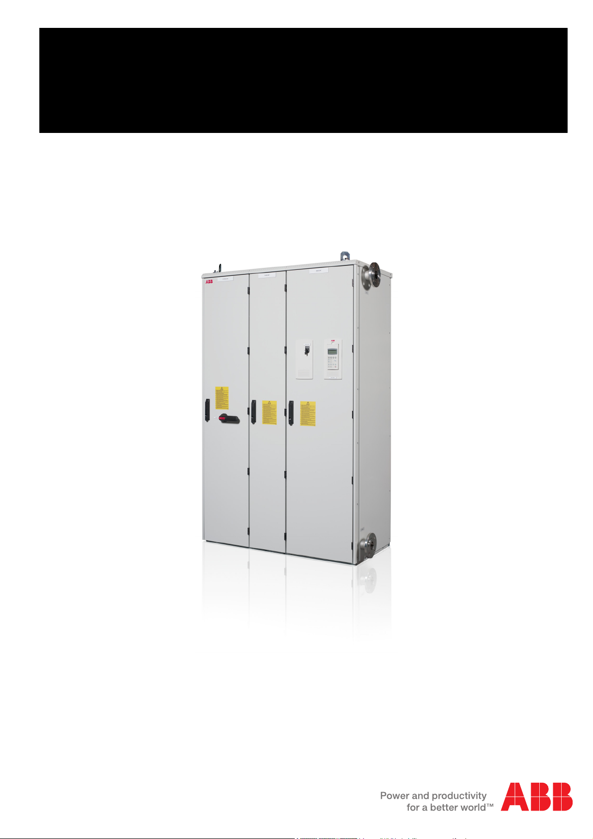
ABB industrial drives
Hardware manual
ACS800-17LC Drives (55 to 5200 kW)

List of related manuals
Drive hardware manuals Code (English)
ACS800-17LC Hardware Manual 3AUA0000065339
ACS800 IGBT Supply Control Program Firmware Manual 3AFE68315735
ACS800 Standard Control Program Firmware Manual 3AFE64527592
Option manuals and guides
ACS800-1007LC Liquid Cooling Unit User’s Manual 3AFE68621101
ACS800-607LC 3-phase Brake Units Hardware Manual 3AFE68835861
ACS800 Brake Control Program Firmware Manual 3AFE68835631
ACW 621 Braking Chopper Sections User’s Manual 3BFE64314874
ACS800 Sine Filters User’s Manual 3AFE68389178
Fieldbus Adapters, I/O Extension Modules etc.
You can find manuals and other product documents in PDF format on the Internet. See section Document
library on the Internet on the inside of the back cover. For manuals not available in the Document library,
contact your local ABB representative.

ACS800-17LC Drives
55 to 5200 kW
Hardware Manual
2016 ABB Oy. All Rights Reserved.
3AUA0000065339 REV B EN
EFFECTIVE: 2016-06-07


Update notice
Code Revision Language
3AFE68715474 C English EN
3AFE68843723 B
German DE
3AFE68843731 B
Finnish FI
3AFE68843740 B
Italian IT
3AFE68843758 B
Swedish SV
3AFE68822092 B
English EN
3AFE68912148 B
German DE
3AFE68912156 B
Finnish FI
3AFE68912164 B
Italian IT
3AFE68912172 B
Swedish SV
3AFE68715491
C English EN
3AFE68987784
C German DE
3AFE68987792
C Finnish FI
3AFE68987806
C Italian IT
3AFE68987814
C Swedish SV
3AFE68835861 D English EN
3AUA0000040346 D
German DE
3AUA0000040370 D
Finnish FI
3AUA0000040368 D
Italian IT
3AFE68621101 E
English EN
3AFE68829887 E
German DE
3AFE68829909 E
Finnish FI
3AFE68829917 E
Italian IT
3AFE68829925 E
Swedish SV
3AFE68620902 E
English EN
3AFE68820821 E
German DE
3AFE68820847 E
Finnish FI
3AFE68820855 E
Italian IT
3AFE68820863 E
Swedish SV
3AUA0000065339 B
English EN
3AUA0000065342 B
English EN
1
ACS800LC liquid-cooled industrial units and drives
coolant change to Antifrogen® L.
Code: 3AXD50000371952 Rev A
Val id : 2019-05-01
Contents:
This notice concerns industrial ACS800 Liquid-cooled
multidrive Units Hardware manuals, ACS800 Liquid-cooled
Single Drive cabinet manuals, ACS800 Liquid Cooling Unit
User's Manual and their respective translations.
Update notice

2
Scope
This change concerns ACS800 Liquid-cooled multidrive Units (ACS800-107LC, 207LC, -307LC, -507LC, -607LC, -1107LC, -1207LC), ACS800-1007LC Liquid
Cooling Unit, ACS800-07LC Drives, ACS800-17LC Drives and ACS800-37LC
Drives manufactured in Finland or Estonia.
New units and drives are tested with Antifrogen® L. Antifrogen® L is a ready-made
propylene glycol based coolant mixture with corrosion inhibitors included. Proper
selection of Antifrogen® L and Adjustment of the Main Choke Valve is described in
the document Usage of Antifrogen® L in ACS800LC Drives (3AXD10000511935).
New units and drives which are tested with Antifrogen® L must be operated with
Antifrogen® L to prevent corrosion in the system. If usage of the old propylene glycol
and corrosion inhibitor Cortec VpCl-649 in new Antifrogen® L tested units and drives
is wanted system must be flushed before as Antifrogen® L remains in the system
after testing. Flushing procedure described in the document Usage of Antifrogen® L
in ACS800LC Drives (3AXD10000511935) must be followed. If new units or drives
tested with Antifrogen® L are connected to old ACS800 industrial liquid-cooled units
or drives, both systems needs to use same the coolant. Mixing propylene glycol and
corrosion inhibitor Cortec VpCl-649 coolant with Antifrogen® L is not allowed.
New units and drives are tested with Antifrogen® L are labelled with information
label (3AXD50000431427) below. The label is installed to LCU-cabinet or incoming
main pipe of the unit if delivered without LCU-cabinet.
This update notice and Usage of Antifrogen® L in ACS800LC Drives
(3AXD10000511935) document are delivered with drive in documentation pocket
inside the cabinet door.
Update notice
Changes to documentation
Replaced Technical data, internal cooling circuit data, Water, Inhibitor, Glycol, Liquid
mixture quality, Temperature limits, Pressure limits and Freeze protection and
corrosion inhibition chapters to following:
Technical data
Coolant specification
Coolant type
Antifrogen®L (by Clariant International Ltd., www.clariant.com) 25% or 50% water
mixture, available from Clariant distributors and ABB Service representatives.
Antifrogen®L 25% mixture is usable in storage temperatures down to -16 °C (3.2
°F). Antifrogen®L 50% mixture is usable in storage temperatures down to -40 °C (40 °F).
Note that operation below 0 °C (32 °F) is not allowed regardless of the freezing point
of the coolant.
WARNING!
3
Temperature limits
Ambient temperature: See the technical data of the drive/unit.
Freeze protection: The freezing point of the coolant is determined by the
concentration of heat transfer fluid in the mixture.
The higher the concentration of heat transfer fluid, the higher the viscosity of the
coolant. This results in a higher pressure loss in the system.
The nominal current ratings of drive system modules apply to Antifrogen®L / water
solution of 25/75 (volume). For derating with other ratios, contact your local ABB
representative.
The warranty does not cover damage occurring from use of improper
coolant.
Update notice

4
The temperature of the coolant must be controlled according to the tables below.
Minimum coolant inlet temperature: Condensation is not allowed. The minimum
coolant temperature to avoid concentration (at an atmospheric pressure of 100 kPa)
is shown below as a function of the relative humidity (
(T
).
air
T
(°C) Min. T
air
ϕ = 95% ϕ = 80%
coolant
ϕ = 65% ϕ = 50% ϕ = 40%
ϕ) and the ambient temperature
(°C)
5
10 9.2 6.7
15 14.2 11.5 8.4
20 19.2 16.5 13.2 9.4 6.0
25 24.1 21.4 17.9 13.8 10.5
30 29.1 26.2 22.7 18.4 15.0
35 34.1 31.1 27.4 23.0 19.4
40 39.0 35.9 32.2 27.6 23.8
45 44.0 40.8 36.8 32.1 28.2
50 49.0 45.6 41.6 36.7 32.8
55 53.9 50.4 46.3 42.2 37.1
4.3 1.9 -0.9 -4.5 -7.4
3.7 -0.1 -3.0
4.6 1.5
= Not allowed as standard but the coolant temperature must be 5 °C or above. Consult an ABB
representative if operation below coolant temperature 5 °C is required.
Example: At an air temperature of 45 °C and relative humidity of 65% the coolant temperature may not
be below +36.8 °C.
Maximum coolant inlet temperature for ACS800 liquid cooled drive
Update notice
Drive with the optional cooling unit (ACS800-1007LC):
• 38 °C when the drive output capacity is not derated
• 38 °C...45 °C when the drive output capacity is derated by 1% per 1 °C
temperature increase.
Drive without the optional liquid cooling unit (ACS800-1007LC):
• 42 °C when the drive output capacity is not derated
• 42 °C...48 °C when the drive output capacity is not derated by 1% per 1 °C
temperature increase.
Maximum temperature rise: 13 °C, depends on the mass flow.

Pressure limits
5
Base pressure: 100...150 kPa (recommended): 200 kPa (maximum). “Base
pressure” denotes the pressure of the system compared with the atmospheric
pressure when the cooling circuit is filled with coolant.
Air counterpressure in the expansion tank: 40 kPa
Design pressure (Ps): 600 kPa
Nominal pressure difference (between main in/out lines): 120 kPa with 25(75%
(volume) coolant solution, 150 kPa with 50/50% coolant solution.
Maximum pressure difference (between main in/out lines): 200 kPa
Update notice

6
Update notice

Table of contents
Table of contents
Safety instructions
What this chapter contains . . . . . . . . . . . . . . . . . . . . . . . . . . . . . . . . . . . . . . . . . . . . . . . . . . . . . . . 13
Use of warnings . . . . . . . . . . . . . . . . . . . . . . . . . . . . . . . . . . . . . . . . . . . . . . . . . . . . . . . . . . . . . . . . 13
Safety in installation and maintenance . . . . . . . . . . . . . . . . . . . . . . . . . . . . . . . . . . . . . . . . . . . . . . 14
Electrical safety . . . . . . . . . . . . . . . . . . . . . . . . . . . . . . . . . . . . . . . . . . . . . . . . . . . . . . . . . . . 14
Grounding . . . . . . . . . . . . . . . . . . . . . . . . . . . . . . . . . . . . . . . . . . . . . . . . . . . . . . . . . . . 15
Permanent magnet motor drives . . . . . . . . . . . . . . . . . . . . . . . . . . . . . . . . . . . . . . . . . 16
General safety . . . . . . . . . . . . . . . . . . . . . . . . . . . . . . . . . . . . . . . . . . . . . . . . . . . . . . . . . . . . 17
Printed circuit boards . . . . . . . . . . . . . . . . . . . . . . . . . . . . . . . . . . . . . . . . . . . . . . . . . . 17
Fiber optic cables . . . . . . . . . . . . . . . . . . . . . . . . . . . . . . . . . . . . . . . . . . . . . . . . . . . . . 17
Use of the hand-operated winch . . . . . . . . . . . . . . . . . . . . . . . . . . . . . . . . . . . . . . . . . . 18
Work on the liquid cooling system . . . . . . . . . . . . . . . . . . . . . . . . . . . . . . . . . . . . . . . . 18
Safe start-up and operation . . . . . . . . . . . . . . . . . . . . . . . . . . . . . . . . . . . . . . . . . . . . . . . . . . . . . . . 19
General safety . . . . . . . . . . . . . . . . . . . . . . . . . . . . . . . . . . . . . . . . . . . . . . . . . . . . . . . . . . . . 19
Permanent magnet motor drives . . . . . . . . . . . . . . . . . . . . . . . . . . . . . . . . . . . . . . . . . 19
5
Introduction to the manual
What this chapter contains . . . . . . . . . . . . . . . . . . . . . . . . . . . . . . . . . . . . . . . . . . . . . . . . . . . . . . . 21
Applicability . . . . . . . . . . . . . . . . . . . . . . . . . . . . . . . . . . . . . . . . . . . . . . . . . . . . . . . . . . . . . . . . . . . 21
Target audience . . . . . . . . . . . . . . . . . . . . . . . . . . . . . . . . . . . . . . . . . . . . . . . . . . . . . . . . . . . . . . . 21
Contents . . . . . . . . . . . . . . . . . . . . . . . . . . . . . . . . . . . . . . . . . . . . . . . . . . . . . . . . . . . . . . . . . . . . . 21
Related documents . . . . . . . . . . . . . . . . . . . . . . . . . . . . . . . . . . . . . . . . . . . . . . . . . . . . . . . . . . . . . 22
Categorization by frame size and option code . . . . . . . . . . . . . . . . . . . . . . . . . . . . . . . . . . . . . . . . 22
Quick installation and start-up flowchart . . . . . . . . . . . . . . . . . . . . . . . . . . . . . . . . . . . . . . . . . . . . . 22
Terms and abbreviations . . . . . . . . . . . . . . . . . . . . . . . . . . . . . . . . . . . . . . . . . . . . . . . . . . . . . . . . . 23
Hardware description
What this chapter contains . . . . . . . . . . . . . . . . . . . . . . . . . . . . . . . . . . . . . . . . . . . . . . . . . . . . . . . 27
Product overview . . . . . . . . . . . . . . . . . . . . . . . . . . . . . . . . . . . . . . . . . . . . . . . . . . . . . . . . . . . . . . . 27
Single-line circuit diagram of the drive . . . . . . . . . . . . . . . . . . . . . . . . . . . . . . . . . . . . . . . . . . . . . . 28
Example circuit diagram (frames R7i+R7i and R8i+R8i) . . . . . . . . . . . . . . . . . . . . . . . . . . . . 28
Example circuit diagram (frame 2×R8i+2×R8i) . . . . . . . . . . . . . . . . . . . . . . . . . . . . . . . . . . . 29
Block diagram of the main circuit with options . . . . . . . . . . . . . . . . . . . . . . . . . . . . . . . . . . . . . . . . 30
General information on drive cabinet layout . . . . . . . . . . . . . . . . . . . . . . . . . . . . . . . . . . . . . . . . . . 31
Cabinet layout (frames R7i+R7i and R8i+R8i) . . . . . . . . . . . . . . . . . . . . . . . . . . . . . . . . . . . . . . . . 32
Swing-out frame layout . . . . . . . . . . . . . . . . . . . . . . . . . . . . . . . . . . . . . . . . . . . . . . . . . . . . . 33
Auxiliary control cubicle layout . . . . . . . . . . . . . . . . . . . . . . . . . . . . . . . . . . . . . . . . . . . . . . . . . . . . 34
Main switch disconnecter cubicle layout (frames 2×R8i+2×R8i and up) . . . . . . . . . . . . . . . . . . . . . 35
600 mm wide cubicle . . . . . . . . . . . . . . . . . . . . . . . . . . . . . . . . . . . . . . . . . . . . . . . . . . . . . . 35
1000 mm wide cubicle . . . . . . . . . . . . . . . . . . . . . . . . . . . . . . . . . . . . . . . . . . . . . . . . . . . . . . 35
Table of contents

6
Layout of LCL filter and supply module cubicles (frame 2×R8i and up) . . . . . . . . . . . . . . . . . . . . . .36
Swing-out frame layout . . . . . . . . . . . . . . . . . . . . . . . . . . . . . . . . . . . . . . . . . . . . . . . . . . . . . .37
Layout of inverter module cubicle (frame 2×R8i) . . . . . . . . . . . . . . . . . . . . . . . . . . . . . . . . . . . . . . .38
Layout of inverter module cubicle (frame 3×R8i) . . . . . . . . . . . . . . . . . . . . . . . . . . . . . . . . . . . . . . .39
Layout of inverter module cubicles (frames 4×R8i to 9×R8i) . . . . . . . . . . . . . . . . . . . . . . . . . . . . . .40
Swing-out frame layout of the inverter module cubicles . . . . . . . . . . . . . . . . . . . . . . . . . . . . . . . . . .40
Overview of supply and inverter modules (R7i and R8i) . . . . . . . . . . . . . . . . . . . . . . . . . . . . . . . . .41
Overview of power and control connections . . . . . . . . . . . . . . . . . . . . . . . . . . . . . . . . . . . . . . . . . . .42
Control of the supply unit . . . . . . . . . . . . . . . . . . . . . . . . . . . . . . . . . . . . . . . . . . . . . . . . . . . . . . . . .43
Main switch-disconnector Q1 (frames R7i+R7i and R8i+R8i) . . . . . . . . . . . . . . . . . . . . . . . . .43
Supply transformer disconnecting push button (+Q959) . . . . . . . . . . . . . . . . . . . . . . . . . . . . .43
Operating switch . . . . . . . . . . . . . . . . . . . . . . . . . . . . . . . . . . . . . . . . . . . . . . . . . . . . . . . . . . .43
Auxiliary power switch Q100 (frame sizes 2×R8i and up) . . . . . . . . . . . . . . . . . . . . . . . . . . . .43
Grounding switch Q9 (option +F259) . . . . . . . . . . . . . . . . . . . . . . . . . . . . . . . . . . . . . . . . . . .43
Emergency stop push button . . . . . . . . . . . . . . . . . . . . . . . . . . . . . . . . . . . . . . . . . . . . . . . . .44
Reset button . . . . . . . . . . . . . . . . . . . . . . . . . . . . . . . . . . . . . . . . . . . . . . . . . . . . . . . . . . . . . .44
Connections and use of the I/O in the supply unit . . . . . . . . . . . . . . . . . . . . . . . . . . . . . . . . . .45
Connections to standard I/O terminals . . . . . . . . . . . . . . . . . . . . . . . . . . . . . . . . . . . . .46
Control of the inverter unit and motor . . . . . . . . . . . . . . . . . . . . . . . . . . . . . . . . . . . . . . . . . . . . . . . .47
Control panel . . . . . . . . . . . . . . . . . . . . . . . . . . . . . . . . . . . . . . . . . . . . . . . . . . . . . . . . . . . . . .47
Connections and use of the I/O in the inverter unit . . . . . . . . . . . . . . . . . . . . . . . . . . . . . . . . .47
Circuit boards . . . . . . . . . . . . . . . . . . . . . . . . . . . . . . . . . . . . . . . . . . . . . . . . . . . . . . . . . . . . . . . . . .47
Type designation labels . . . . . . . . . . . . . . . . . . . . . . . . . . . . . . . . . . . . . . . . . . . . . . . . . . . . . . . . . .48
Drive label . . . . . . . . . . . . . . . . . . . . . . . . . . . . . . . . . . . . . . . . . . . . . . . . . . . . . . . . . . . . . . . .48
Supply, inverter and brake module label . . . . . . . . . . . . . . . . . . . . . . . . . . . . . . . . . . . . . . . . .48
Type designation key . . . . . . . . . . . . . . . . . . . . . . . . . . . . . . . . . . . . . . . . . . . . . . . . . . . . . . . . . . . .50
Type code of the basic configuration . . . . . . . . . . . . . . . . . . . . . . . . . . . . . . . . . . . . . . . . . . .50
Option codes . . . . . . . . . . . . . . . . . . . . . . . . . . . . . . . . . . . . . . . . . . . . . . . . . . . . . . . . . . . . . .50
Mechanical installation
What this chapter contains . . . . . . . . . . . . . . . . . . . . . . . . . . . . . . . . . . . . . . . . . . . . . . . . . . . . . . . .55
Checking the installation site . . . . . . . . . . . . . . . . . . . . . . . . . . . . . . . . . . . . . . . . . . . . . . . . . . . . . .55
Required tools . . . . . . . . . . . . . . . . . . . . . . . . . . . . . . . . . . . . . . . . . . . . . . . . . . . . . . . . . . . . . . . . .55
Checking the delivery . . . . . . . . . . . . . . . . . . . . . . . . . . . . . . . . . . . . . . . . . . . . . . . . . . . . . . . . . . . .56
Moving the unit . . . . . . . . . . . . . . . . . . . . . . . . . . . . . . . . . . . . . . . . . . . . . . . . . . . . . . . . . . . . . . . . .56
Moving the unit by crane . . . . . . . . . . . . . . . . . . . . . . . . . . . . . . . . . . . . . . . . . . . . . . . . . . . . .56
Moving the unit by fork-lift or pallet truck . . . . . . . . . . . . . . . . . . . . . . . . . . . . . . . . . . . . . . . . .57
Moving the unit on rollers (not allowed with marine cabinets) . . . . . . . . . . . . . . . . . . . . . . . . .57
Laying the unit on its back . . . . . . . . . . . . . . . . . . . . . . . . . . . . . . . . . . . . . . . . . . . . . . . . . . . .57
Placing the unit . . . . . . . . . . . . . . . . . . . . . . . . . . . . . . . . . . . . . . . . . . . . . . . . . . . . . . . . . . . . . . . . .58
Overview of the installation procedure . . . . . . . . . . . . . . . . . . . . . . . . . . . . . . . . . . . . . . . . . . . . . . .59
Fastening the cabinet to the floor and wall (non-marine units) . . . . . . . . . . . . . . . . . . . . . . . . . . . . .60
Alternative 1 – Clamping . . . . . . . . . . . . . . . . . . . . . . . . . . . . . . . . . . . . . . . . . . . . . . . . . . . . .60
Alternative 2 – Using the holes inside the cabinet . . . . . . . . . . . . . . . . . . . . . . . . . . . . . . . . .61
Fastening the unit to the floor and wall (marine units, option +C121) . . . . . . . . . . . . . . . . . . . . . . .62
Joining the shipping splits . . . . . . . . . . . . . . . . . . . . . . . . . . . . . . . . . . . . . . . . . . . . . . . . . . . . . . . .63
Preparing the liquid pipe connections . . . . . . . . . . . . . . . . . . . . . . . . . . . . . . . . . . . . . . . . . . .63
Fastening the cabinets together . . . . . . . . . . . . . . . . . . . . . . . . . . . . . . . . . . . . . . . . . . . . . . .63
Connecting the liquid pipes . . . . . . . . . . . . . . . . . . . . . . . . . . . . . . . . . . . . . . . . . . . . . . . . . . .64
Table of contents

Connecting the PE busbars . . . . . . . . . . . . . . . . . . . . . . . . . . . . . . . . . . . . . . . . . . . . . . . . . . 64
Connecting the DC busbars . . . . . . . . . . . . . . . . . . . . . . . . . . . . . . . . . . . . . . . . . . . . . . . . . . 65
Miscellaneous . . . . . . . . . . . . . . . . . . . . . . . . . . . . . . . . . . . . . . . . . . . . . . . . . . . . . . . . . . . . . . . . . 66
Cable duct in the floor below the cabinet . . . . . . . . . . . . . . . . . . . . . . . . . . . . . . . . . . . . . . . . 66
Electric welding . . . . . . . . . . . . . . . . . . . . . . . . . . . . . . . . . . . . . . . . . . . . . . . . . . . . . . . . . . . 67
Planning the electrical installation
What this chapter contains . . . . . . . . . . . . . . . . . . . . . . . . . . . . . . . . . . . . . . . . . . . . . . . . . . . . . . . 69
Selecting the supply disconnecting device (disconnecting means) . . . . . . . . . . . . . . . . . . . . . . . . . 69
Checking the compatibility of the motor and drive . . . . . . . . . . . . . . . . . . . . . . . . . . . . . . . . . . . . . . 69
Protecting the motor insulation and bearings . . . . . . . . . . . . . . . . . . . . . . . . . . . . . . . . . . . . . 70
Requirements for motor insulation and bearings and drive filters . . . . . . . . . . . . . . . . . . . . . 71
Explosion-safe (EX) motors . . . . . . . . . . . . . . . . . . . . . . . . . . . . . . . . . . . . . . . . . . . . . 72
High-output motors and IP 23 motors . . . . . . . . . . . . . . . . . . . . . . . . . . . . . . . . . . . . . . 73
HXR and AMA motors . . . . . . . . . . . . . . . . . . . . . . . . . . . . . . . . . . . . . . . . . . . . . . . . . 73
ABB motors of types other than M2_, M3_, HX_ and AM_ . . . . . . . . . . . . . . . . . . . . . 73
When DC link voltage is increased with parameter settings . . . . . . . . . . . . . . . . . . . . . 73
Calculating the rise time and the peak line-to-line voltage . . . . . . . . . . . . . . . . . . . . . . 73
Sine filters . . . . . . . . . . . . . . . . . . . . . . . . . . . . . . . . . . . . . . . . . . . . . . . . . . . . . . . . . . . 74
Selecting the power cables . . . . . . . . . . . . . . . . . . . . . . . . . . . . . . . . . . . . . . . . . . . . . . . . . . . . . . . 74
General rules . . . . . . . . . . . . . . . . . . . . . . . . . . . . . . . . . . . . . . . . . . . . . . . . . . . . . . . . . . . . . 74
Typical power cable sizes . . . . . . . . . . . . . . . . . . . . . . . . . . . . . . . . . . . . . . . . . . . . . . . . . . . 76
Alternative power cable types . . . . . . . . . . . . . . . . . . . . . . . . . . . . . . . . . . . . . . . . . . . . . . . . 78
Motor cable shield . . . . . . . . . . . . . . . . . . . . . . . . . . . . . . . . . . . . . . . . . . . . . . . . . . . . . . . . . 78
Additional US requirements . . . . . . . . . . . . . . . . . . . . . . . . . . . . . . . . . . . . . . . . . . . . . . . . . . 79
Conduit . . . . . . . . . . . . . . . . . . . . . . . . . . . . . . . . . . . . . . . . . . . . . . . . . . . . . . . . . . . . . 79
Armored cable / shielded power cable . . . . . . . . . . . . . . . . . . . . . . . . . . . . . . . . . . . . . 79
Selecting the control cables . . . . . . . . . . . . . . . . . . . . . . . . . . . . . . . . . . . . . . . . . . . . . . . . . . . . . . 79
General rules . . . . . . . . . . . . . . . . . . . . . . . . . . . . . . . . . . . . . . . . . . . . . . . . . . . . . . . . . . . . . 79
Relay cable . . . . . . . . . . . . . . . . . . . . . . . . . . . . . . . . . . . . . . . . . . . . . . . . . . . . . . . . . . . . . . 80
Control panel cable . . . . . . . . . . . . . . . . . . . . . . . . . . . . . . . . . . . . . . . . . . . . . . . . . . . . . . . . 80
Coaxial cable (for use with Advant Controllers AC 80/AC 800) . . . . . . . . . . . . . . . . . . . . . . . 80
Routing the cables . . . . . . . . . . . . . . . . . . . . . . . . . . . . . . . . . . . . . . . . . . . . . . . . . . . . . . . . . . . . . . 80
Separate control cable ducts . . . . . . . . . . . . . . . . . . . . . . . . . . . . . . . . . . . . . . . . . . . . . . . . . 81
Protecting the drive, input power cable, motor and motor cable in short circuit situation and against
thermal overload . . . . . . . . . . . . . . . . . . . . . . . . . . . . . . . . . . . . . . . . . . . . . . . . . . . . . . . . . . . . . . . 81
Protecting the drive and input power cable in short-circuit situations . . . . . . . . . . . . . . . . . . 81
Protecting the motor and motor cable in short-circuit situations . . . . . . . . . . . . . . . . . . . . . . 82
Protecting the drive, motor cable and input power cable against thermal overload . . . . . . . . 82
Protecting the motor against thermal overload . . . . . . . . . . . . . . . . . . . . . . . . . . . . . . . . . . . 82
Insulation requirements for the motor temperature sensor circuit . . . . . . . . . . . . . . . . 83
Protecting the drive against ground faults in the drive, motor or motor cable . . . . . . . . . . . . . . . . . 83
Implementing the emergency stop function . . . . . . . . . . . . . . . . . . . . . . . . . . . . . . . . . . . . . . . . . . . 83
Implementing the Prevention of unexpected start function . . . . . . . . . . . . . . . . . . . . . . . . . . . . . . . 84
Implementing the Safe torque off function . . . . . . . . . . . . . . . . . . . . . . . . . . . . . . . . . . . . . . . . . . . . 85
Implementing the power-loss ride-through function . . . . . . . . . . . . . . . . . . . . . . . . . . . . . . . . . . . . 85
Supplying power for the auxiliary circuits . . . . . . . . . . . . . . . . . . . . . . . . . . . . . . . . . . . . . . . . . . . . 85
Terminals for connecting external control voltage (option +G307) . . . . . . . . . . . . . . . . . . . . 86
Units without optional auxiliary control transformer and without terminals for connecting external
7
Table of contents

8
control voltage (option +G307) . . . . . . . . . . . . . . . . . . . . . . . . . . . . . . . . . . . . . . . . . . . . . . . .86
Using power factor compensation capacitors with the drive . . . . . . . . . . . . . . . . . . . . . . . . . . . . . .86
Implementing a safety switch between the drive and motor . . . . . . . . . . . . . . . . . . . . . . . . . . . . . . .87
Using a contactor between the drive and motor . . . . . . . . . . . . . . . . . . . . . . . . . . . . . . . . . . . . . . . .87
Implementing a bypass connection . . . . . . . . . . . . . . . . . . . . . . . . . . . . . . . . . . . . . . . . . . . . . . . . .88
Example bypass connection . . . . . . . . . . . . . . . . . . . . . . . . . . . . . . . . . . . . . . . . . . . . . . . . . .88
Switching the motor power supply from drive to direct-on-line . . . . . . . . . . . . . . . . . . .88
Switching the motor power supply from direct-on-line to drive . . . . . . . . . . . . . . . . . . .89
Protecting the contacts of relay outputs . . . . . . . . . . . . . . . . . . . . . . . . . . . . . . . . . . . . . . . . . . . . . .89
Considering the PELV on installation sites above 2000 metres (6562 feet) . . . . . . . . . . . . . . . . . .90
Electrical installation
What this chapter contains . . . . . . . . . . . . . . . . . . . . . . . . . . . . . . . . . . . . . . . . . . . . . . . . . . . . . . . .91
Checking the insulation of the assembly . . . . . . . . . . . . . . . . . . . . . . . . . . . . . . . . . . . . . . . . . . . . .91
Drive . . . . . . . . . . . . . . . . . . . . . . . . . . . . . . . . . . . . . . . . . . . . . . . . . . . . . . . . . . . . . . . . . . . .91
Supply cable . . . . . . . . . . . . . . . . . . . . . . . . . . . . . . . . . . . . . . . . . . . . . . . . . . . . . . . . . . . . . .91
Motor and motor cable . . . . . . . . . . . . . . . . . . . . . . . . . . . . . . . . . . . . . . . . . . . . . . . . . . . . . .91
Braking resistor assembly . . . . . . . . . . . . . . . . . . . . . . . . . . . . . . . . . . . . . . . . . . . . . . . . . . . .92
Checking the compatibility with IT (ungrounded) and corner grounded TN systems . . . . . . . . . . . .92
Connecting the input power cable . . . . . . . . . . . . . . . . . . . . . . . . . . . . . . . . . . . . . . . . . . . . . . . . . .93
Connection diagram . . . . . . . . . . . . . . . . . . . . . . . . . . . . . . . . . . . . . . . . . . . . . . . . . . . . . . . .93
Connection procedure . . . . . . . . . . . . . . . . . . . . . . . . . . . . . . . . . . . . . . . . . . . . . . . . . . . . . . .93
Connecting the motor cable – units with no common motor terminals cubicle option +H359 . . . . .94
Connection diagram – single inverter module feeds one motor . . . . . . . . . . . . . . . . . . . . . . .94
Connection diagram – parallel inverter modules feed one motor . . . . . . . . . . . . . . . . . . . . . .95
Connection procedure . . . . . . . . . . . . . . . . . . . . . . . . . . . . . . . . . . . . . . . . . . . . . . . . . . . . . . .96
Connecting the motor cable (units with the common motor cable connection terminals cubicle option
+H359) . . . . . . . . . . . . . . . . . . . . . . . . . . . . . . . . . . . . . . . . . . . . . . . . . . . . . . . . . . . . . . . . . . . . . . .98
Connection diagram . . . . . . . . . . . . . . . . . . . . . . . . . . . . . . . . . . . . . . . . . . . . . . . . . . . . . . . .98
Connection procedure . . . . . . . . . . . . . . . . . . . . . . . . . . . . . . . . . . . . . . . . . . . . . . . . . . . . . . .98
Connecting external power supply for the auxiliary circuits . . . . . . . . . . . . . . . . . . . . . . . . . . . . . .100
Frames R7i×R7i and R8i×R8i . . . . . . . . . . . . . . . . . . . . . . . . . . . . . . . . . . . . . . . . . . . . . . . .100
Frames 2×R8i and up . . . . . . . . . . . . . . . . . . . . . . . . . . . . . . . . . . . . . . . . . . . . . . . . . . . . . .101
Standard unit without optional auxiliary control voltage transformer or terminals for con-
necting external control voltage . . . . . . . . . . . . . . . . . . . . . . . . . . . . . . . . . . . . . . . . . .101
Units with optional auxiliary control voltage transformer and without terminals for connect-
ing external control voltage (+G307) . . . . . . . . . . . . . . . . . . . . . . . . . . . . . . . . . . . . . .101
Units with terminals for connecting external control voltage (option +G307) and without op-
tional auxiliary control voltage transformer . . . . . . . . . . . . . . . . . . . . . . . . . . . . . . . . .102
Connecting the control cables for the supply unit . . . . . . . . . . . . . . . . . . . . . . . . . . . . . . . . . . . . . .102
Connecting the control cables for the inverter unit . . . . . . . . . . . . . . . . . . . . . . . . . . . . . . . . . . . . .103
Default I/O connection diagram . . . . . . . . . . . . . . . . . . . . . . . . . . . . . . . . . . . . . . . . . . . . . . .103
Connection procedure . . . . . . . . . . . . . . . . . . . . . . . . . . . . . . . . . . . . . . . . . . . . . . . . . . . . . .105
Connecting a PC . . . . . . . . . . . . . . . . . . . . . . . . . . . . . . . . . . . . . . . . . . . . . . . . . . . . . . . . . . . . . .106
Installing optional modules . . . . . . . . . . . . . . . . . . . . . . . . . . . . . . . . . . . . . . . . . . . . . . . . . . . . . . .106
Cabling of I/O and fieldbus modules . . . . . . . . . . . . . . . . . . . . . . . . . . . . . . . . . . . . . . . . . . .107
Cabling of pulse encoder interface module . . . . . . . . . . . . . . . . . . . . . . . . . . . . . . . . . . . . . .107
Fiber optic links . . . . . . . . . . . . . . . . . . . . . . . . . . . . . . . . . . . . . . . . . . . . . . . . . . . . . . . . . . .107
Table of contents

Installation checklist
What this chapter contains . . . . . . . . . . . . . . . . . . . . . . . . . . . . . . . . . . . . . . . . . . . . . . . . . . . . . . 109
Installation checklist . . . . . . . . . . . . . . . . . . . . . . . . . . . . . . . . . . . . . . . . . . . . . . . . . . . . . . . . . . . 109
Start-up
What this chapter contains . . . . . . . . . . . . . . . . . . . . . . . . . . . . . . . . . . . . . . . . . . . . . . . . . . . . . . 111
Start-up procedure . . . . . . . . . . . . . . . . . . . . . . . . . . . . . . . . . . . . . . . . . . . . . . . . . . . . . . . . . . . . 111
Safety . . . . . . . . . . . . . . . . . . . . . . . . . . . . . . . . . . . . . . . . . . . . . . . . . . . . . . . . . . . . . . . . . . 111
Checks with no voltage connected . . . . . . . . . . . . . . . . . . . . . . . . . . . . . . . . . . . . . . . . . . . 111
Connecting voltage to the input terminals and auxiliary circuit . . . . . . . . . . . . . . . . . . . . . . 112
Closing the main contactor/breaker . . . . . . . . . . . . . . . . . . . . . . . . . . . . . . . . . . . . . . . . . . . 112
Checking the setting of the ground fault monitoring device . . . . . . . . . . . . . . . . . . . . . . . . . 112
Supply unit control program set-up . . . . . . . . . . . . . . . . . . . . . . . . . . . . . . . . . . . . . . . . . . . 112
Inverter unit control program set-up . . . . . . . . . . . . . . . . . . . . . . . . . . . . . . . . . . . . . . . . . . . 112
Liquid cooling unit control program set-up . . . . . . . . . . . . . . . . . . . . . . . . . . . . . . . . . . . . . . . . . . 112
On-load checks . . . . . . . . . . . . . . . . . . . . . . . . . . . . . . . . . . . . . . . . . . . . . . . . . . . . . . . . . . 113
Switching the control panel between the supply and inverter units . . . . . . . . . . . . . . . . . . . . . . . . 114
ACS800-17LC-specific parameters in the IGBT Supply Control Program . . . . . . . . . . . . . . . . . . 115
Terms and abbreviations . . . . . . . . . . . . . . . . . . . . . . . . . . . . . . . . . . . . . . . . . . . . . . . . . . . 115
Parameters . . . . . . . . . . . . . . . . . . . . . . . . . . . . . . . . . . . . . . . . . . . . . . . . . . . . . . . . . . . . . 115
Default values of parameters with the ACS800-17LC . . . . . . . . . . . . . . . . . . . . . . . . . . . . . 116
ACS800-17LC-specific parameters in the application program . . . . . . . . . . . . . . . . . . . . . . . . . . 117
Terms and abbreviations . . . . . . . . . . . . . . . . . . . . . . . . . . . . . . . . . . . . . . . . . . . . . . . . . . . 117
Actual signals and parameters of supply unit in inverter unit program . . . . . . . . . . . . . . . . 117
9
Fault tracing
LEDs . . . . . . . . . . . . . . . . . . . . . . . . . . . . . . . . . . . . . . . . . . . . . . . . . . . . . . . . . . . . . . . . . . . . . . . 119
Warning and fault messages . . . . . . . . . . . . . . . . . . . . . . . . . . . . . . . . . . . . . . . . . . . . . . . . . . . . . 119
Warning/Fault message from the unit not being monitored by the control panel . . . . . . . . . 119
Conflicting ID numbers . . . . . . . . . . . . . . . . . . . . . . . . . . . . . . . . . . . . . . . . . . . . . . . . . . . . . 119
Maintenance
What this chapter contains . . . . . . . . . . . . . . . . . . . . . . . . . . . . . . . . . . . . . . . . . . . . . . . . . . . . . . 121
Maintenance intervals . . . . . . . . . . . . . . . . . . . . . . . . . . . . . . . . . . . . . . . . . . . . . . . . . . . . . . . . . . 121
Fans . . . . . . . . . . . . . . . . . . . . . . . . . . . . . . . . . . . . . . . . . . . . . . . . . . . . . . . . . . . . . . . . . . . . . . . 121
Replacing the cooling fan of converter module (frames R7i and R8i) . . . . . . . . . . . . . . . . . 121
Replacing the additional fan in the incoming cubicle (frames R7i+R7i and R8i+R8i) . . . . . 122
Replacing the auxiliary control cubicle fan (frames 2×R8i+2×R8i and up) . . . . . . . . . . . . . 123
Replacing the fan in the incoming cubicle (frames 2×R8i+2×R8i and up) . . . . . . . . . . . . . . 124
Replacing the cooling fans in supply module cubicle . . . . . . . . . . . . . . . . . . . . . . . . . . . . . . 125
Replacing the inverter module fans (2×R8i and up) . . . . . . . . . . . . . . . . . . . . . . . . . . . . . . . 126
Replacing the additional fan in the common motor terminals cubicle . . . . . . . . . . . . . . . . . 126
Reduced run capability . . . . . . . . . . . . . . . . . . . . . . . . . . . . . . . . . . . . . . . . . . . . . . . . . . . . . . . . . 127
Replacing supply and inverter modules . . . . . . . . . . . . . . . . . . . . . . . . . . . . . . . . . . . . . . . . . . . . 128
Installing the winch . . . . . . . . . . . . . . . . . . . . . . . . . . . . . . . . . . . . . . . . . . . . . . . . . . . . . . . . . . . . 132
Installing the installation stand . . . . . . . . . . . . . . . . . . . . . . . . . . . . . . . . . . . . . . . . . . . . . . . . . . . 133
Capacitors . . . . . . . . . . . . . . . . . . . . . . . . . . . . . . . . . . . . . . . . . . . . . . . . . . . . . . . . . . . . . . . . . . . 134
Table of contents

10
Reforming the capacitors . . . . . . . . . . . . . . . . . . . . . . . . . . . . . . . . . . . . . . . . . . . . . . . . . . .134
Replacing the capacitors . . . . . . . . . . . . . . . . . . . . . . . . . . . . . . . . . . . . . . . . . . . . . . . . . . . .134
Control panel . . . . . . . . . . . . . . . . . . . . . . . . . . . . . . . . . . . . . . . . . . . . . . . . . . . . . . . . . . . . . . . . .134
Cleaning the control panel . . . . . . . . . . . . . . . . . . . . . . . . . . . . . . . . . . . . . . . . . . . . . . . . . .134
Replacing the PPCS branching unit (APBU-xx) memory backup battery . . . . . . . . . . . . . . . . . . .135
Internal cooling circuit
General . . . . . . . . . . . . . . . . . . . . . . . . . . . . . . . . . . . . . . . . . . . . . . . . . . . . . . . . . . . . . . . . . . . . . .137
Internal cooling system diagram . . . . . . . . . . . . . . . . . . . . . . . . . . . . . . . . . . . . . . . . . . . . . . . . . . .137
Connection to a cooling unit . . . . . . . . . . . . . . . . . . . . . . . . . . . . . . . . . . . . . . . . . . . . . . . . . . . . . .138
Connection to an ACS800-1007LC cooling unit . . . . . . . . . . . . . . . . . . . . . . . . . . . . . . . . . .138
Connection to a custom cooling unit . . . . . . . . . . . . . . . . . . . . . . . . . . . . . . . . . . . . . . . . . . .138
General requirements . . . . . . . . . . . . . . . . . . . . . . . . . . . . . . . . . . . . . . . . . . . . . . . . .138
Coolant temperature control . . . . . . . . . . . . . . . . . . . . . . . . . . . . . . . . . . . . . . . . . . . .138
Installation . . . . . . . . . . . . . . . . . . . . . . . . . . . . . . . . . . . . . . . . . . . . . . . . . . . . . . . . . .138
Filling up and bleeding the internal cooling circuit . . . . . . . . . . . . . . . . . . . . . . . . . . . . . . . . . . . . .139
Drive line-ups with an ACS800-1007LC cooling unit . . . . . . . . . . . . . . . . . . . . . . . . . . . . . .139
Drive line-ups with a custom cooling unit . . . . . . . . . . . . . . . . . . . . . . . . . . . . . . . . . . . . . . .139
Draining the internal cooling circuit . . . . . . . . . . . . . . . . . . . . . . . . . . . . . . . . . . . . . . . . . . . . . . . .140
Adding inhibitor . . . . . . . . . . . . . . . . . . . . . . . . . . . . . . . . . . . . . . . . . . . . . . . . . . . . . . . . . . . . . . . .140
Specifications . . . . . . . . . . . . . . . . . . . . . . . . . . . . . . . . . . . . . . . . . . . . . . . . . . . . . . . . . . . . . . . . .141
Temperature limits . . . . . . . . . . . . . . . . . . . . . . . . . . . . . . . . . . . . . . . . . . . . . . . . . . . . . . . .141
Pressure limits . . . . . . . . . . . . . . . . . . . . . . . . . . . . . . . . . . . . . . . . . . . . . . . . . . . . . . . . . . . .141
Water quality . . . . . . . . . . . . . . . . . . . . . . . . . . . . . . . . . . . . . . . . . . . . . . . . . . . . . . . . . . . .142
Freeze protection and corrosion inhibition . . . . . . . . . . . . . . . . . . . . . . . . . . . . . . . . . . . . . .142
Glycol concentration . . . . . . . . . . . . . . . . . . . . . . . . . . . . . . . . . . . . . . . . . . . . . . . . . .142
Materials . . . . . . . . . . . . . . . . . . . . . . . . . . . . . . . . . . . . . . . . . . . . . . . . . . . . . . . . . . . . . . . .143
Technical data
What this chapter contains . . . . . . . . . . . . . . . . . . . . . . . . . . . . . . . . . . . . . . . . . . . . . . . . . . . . . . .145
Ratings . . . . . . . . . . . . . . . . . . . . . . . . . . . . . . . . . . . . . . . . . . . . . . . . . . . . . . . . . . . . . . . . . . . . . .145
Definitions . . . . . . . . . . . . . . . . . . . . . . . . . . . . . . . . . . . . . . . . . . . . . . . . . . . . . . . . . . . . . . .146
Derating . . . . . . . . . . . . . . . . . . . . . . . . . . . . . . . . . . . . . . . . . . . . . . . . . . . . . . . . . . . . . . . . .146
Temperature derating . . . . . . . . . . . . . . . . . . . . . . . . . . . . . . . . . . . . . . . . . . . . . . . . .146
Altitude derating . . . . . . . . . . . . . . . . . . . . . . . . . . . . . . . . . . . . . . . . . . . . . . . . . . . . . .147
Type equivalence table . . . . . . . . . . . . . . . . . . . . . . . . . . . . . . . . . . . . . . . . . . . . . . . . . . . . . . . . .147
1-phase brake choppers (option +D150) and resistors (option +D151) . . . . . . . . . . . . . . . . . . . . .148
3-phase brake units (option +D152) . . . . . . . . . . . . . . . . . . . . . . . . . . . . . . . . . . . . . . . . . . . . . . . .148
Fuses . . . . . . . . . . . . . . . . . . . . . . . . . . . . . . . . . . . . . . . . . . . . . . . . . . . . . . . . . . . . . . . . . . . . . . .150
Main circuit AC fuses . . . . . . . . . . . . . . . . . . . . . . . . . . . . . . . . . . . . . . . . . . . . . . . . . . . . . .150
Main circuit DC fuses . . . . . . . . . . . . . . . . . . . . . . . . . . . . . . . . . . . . . . . . . . . . . . . . . . . . . .151
Dimensions, weights and free space requirements . . . . . . . . . . . . . . . . . . . . . . . . . . . . . . . . . . . .152
Losses, cooling data and noise . . . . . . . . . . . . . . . . . . . . . . . . . . . . . . . . . . . . . . . . . . . . . . . . . . .153
Internal cooling circuit data . . . . . . . . . . . . . . . . . . . . . . . . . . . . . . . . . . . . . . . . . . . . . . . . . . . . . . .154
Terminal and lead-through data for the input power cable . . . . . . . . . . . . . . . . . . . . . . . . . . . . . . .155
Terminal and lead-through data for the motor cable . . . . . . . . . . . . . . . . . . . . . . . . . . . . . . . . . . .156
Units without common motor terminal cubicle (no option +H359) . . . . . . . . . . . . . . . . . . . . .156
Units with the Common Motor Terminal (CMT) cubicle (option +H359) . . . . . . . . . . . . . . .157
Table of contents

11
Terminal and lead-through data for the resistor cable . . . . . . . . . . . . . . . . . . . . . . . . . . . . . . . . . . 157
Terminal and lead-through data for the control cables . . . . . . . . . . . . . . . . . . . . . . . . . . . . . . . . . 157
Electrical power network specification . . . . . . . . . . . . . . . . . . . . . . . . . . . . . . . . . . . . . . . . . . . . . . 158
Motor connection data . . . . . . . . . . . . . . . . . . . . . . . . . . . . . . . . . . . . . . . . . . . . . . . . . . . . . . . . . . 158
Brake resistor connection data . . . . . . . . . . . . . . . . . . . . . . . . . . . . . . . . . . . . . . . . . . . . . . . . . . . 158
Control unit (RDCU/RMIO) connection data . . . . . . . . . . . . . . . . . . . . . . . . . . . . . . . . . . . . . . . . . 159
Analog inputs . . . . . . . . . . . . . . . . . . . . . . . . . . . . . . . . . . . . . . . . . . . . . . . . . . . . . . . . . . . . 159
Constant voltage output . . . . . . . . . . . . . . . . . . . . . . . . . . . . . . . . . . . . . . . . . . . . . . . . . . . . 159
Auxiliary power output . . . . . . . . . . . . . . . . . . . . . . . . . . . . . . . . . . . . . . . . . . . . . . . . . . . . . 159
Analog outputs . . . . . . . . . . . . . . . . . . . . . . . . . . . . . . . . . . . . . . . . . . . . . . . . . . . . . . . . . . . 159
Digital inputs . . . . . . . . . . . . . . . . . . . . . . . . . . . . . . . . . . . . . . . . . . . . . . . . . . . . . . . . . . . . 159
Relay outputs . . . . . . . . . . . . . . . . . . . . . . . . . . . . . . . . . . . . . . . . . . . . . . . . . . . . . . . . . . . . 160
DDCS fibre optic link . . . . . . . . . . . . . . . . . . . . . . . . . . . . . . . . . . . . . . . . . . . . . . . . . . . . . . 160
24 V DC power input . . . . . . . . . . . . . . . . . . . . . . . . . . . . . . . . . . . . . . . . . . . . . . . . . . . . . . 160
Isolation and grounding diagram . . . . . . . . . . . . . . . . . . . . . . . . . . . . . . . . . . . . . . . . . . . . . 161
Ambient conditions . . . . . . . . . . . . . . . . . . . . . . . . . . . . . . . . . . . . . . . . . . . . . . . . . . . . . . . . . . . . 162
Materials . . . . . . . . . . . . . . . . . . . . . . . . . . . . . . . . . . . . . . . . . . . . . . . . . . . . . . . . . . . . . . . . . . . . 162
Efficiency . . . . . . . . . . . . . . . . . . . . . . . . . . . . . . . . . . . . . . . . . . . . . . . . . . . . . . . . . . . . . . . . . . . . 162
Degree of protection . . . . . . . . . . . . . . . . . . . . . . . . . . . . . . . . . . . . . . . . . . . . . . . . . . . . . . . . . . . 162
Auxiliary circuit current consumption . . . . . . . . . . . . . . . . . . . . . . . . . . . . . . . . . . . . . . . . . . . . . . . 164
Applicable standards . . . . . . . . . . . . . . . . . . . . . . . . . . . . . . . . . . . . . . . . . . . . . . . . . . . . . . . . . . . 165
CE marking . . . . . . . . . . . . . . . . . . . . . . . . . . . . . . . . . . . . . . . . . . . . . . . . . . . . . . . . . . . . . . . . . . 166
Compliance with the European Low Voltage Directive . . . . . . . . . . . . . . . . . . . . . . . . . . . . 166
Compliance with the European EMC Directive . . . . . . . . . . . . . . . . . . . . . . . . . . . . . . . . . . 166
Compliance with the European Machinery Directive . . . . . . . . . . . . . . . . . . . . . . . . . . . . . . 166
Compliance with EN 61800-3:2004 . . . . . . . . . . . . . . . . . . . . . . . . . . . . . . . . . . . . . . . . . . . . . . . . 166
Definitions . . . . . . . . . . . . . . . . . . . . . . . . . . . . . . . . . . . . . . . . . . . . . . . . . . . . . . . . . . . . . . 166
Category C2 . . . . . . . . . . . . . . . . . . . . . . . . . . . . . . . . . . . . . . . . . . . . . . . . . . . . . . . . . . . . . 167
Category C3 . . . . . . . . . . . . . . . . . . . . . . . . . . . . . . . . . . . . . . . . . . . . . . . . . . . . . . . . . . . . . 167
Category C4 . . . . . . . . . . . . . . . . . . . . . . . . . . . . . . . . . . . . . . . . . . . . . . . . . . . . . . . . . . . . . 168
UL marking . . . . . . . . . . . . . . . . . . . . . . . . . . . . . . . . . . . . . . . . . . . . . . . . . . . . . . . . . . . . . . . . . . 169
UL checklist . . . . . . . . . . . . . . . . . . . . . . . . . . . . . . . . . . . . . . . . . . . . . . . . . . . . . . . . . . . . . 169
CSA marking . . . . . . . . . . . . . . . . . . . . . . . . . . . . . . . . . . . . . . . . . . . . . . . . . . . . . . . . . . . . . . . . . 169
Approvals . . . . . . . . . . . . . . . . . . . . . . . . . . . . . . . . . . . . . . . . . . . . . . . . . . . . . . . . . . . . . . . . . . . 169
Cyber security disclaimer . . . . . . . . . . . . . . . . . . . . . . . . . . . . . . . . . . . . . . . . . . . . . . . . . . . . . . . 170
Disclaimer . . . . . . . . . . . . . . . . . . . . . . . . . . . . . . . . . . . . . . . . . . . . . . . . . . . . . . . . . . . . . . . . . . . 170
Dimensions
What this chapter contains . . . . . . . . . . . . . . . . . . . . . . . . . . . . . . . . . . . . . . . . . . . . . . . . . . . . . . 171
Table of dimensions . . . . . . . . . . . . . . . . . . . . . . . . . . . . . . . . . . . . . . . . . . . . . . . . . . . . . . . . . . . 171
Frame sizes R7i+R7i and R8i+R8i (bottom entry/exit) . . . . . . . . . . . . . . . . . . . . . . . . . . . . . . . . . 173
Frame sizes R7i+R7i and R8i+R8i (marine units, +C121) . . . . . . . . . . . . . . . . . . . . . . . . . . . . . . 174
Product and service inquiries . . . . . . . . . . . . . . . . . . . . . . . . . . . . . . . . . . . . . . . . . . . . . . . . . . . . 175
Product training . . . . . . . . . . . . . . . . . . . . . . . . . . . . . . . . . . . . . . . . . . . . . . . . . . . . . . . . . . . . . . . 175
Providing feedback on ABB manuals . . . . . . . . . . . . . . . . . . . . . . . . . . . . . . . . . . . . . . . . . . . . . . 175
Document library on the Internet . . . . . . . . . . . . . . . . . . . . . . . . . . . . . . . . . . . . . . . . . . . . . . . . . . 175
Table of contents

12
Table of contents
Safety instructions
What this chapter contains
This chapter contains safety instructions you must follow when installing, operating
and servicing the drive. If ignored, physical injury or death may follow, or damage
may occur to the drive, motor or driven equipment. Read the safety instructions
before you work on the unit.
Use of warnings
Warnings caution you about conditions which can result in serious injury or death
and/or damage to the equipment, and advise on how to avoid the danger. The
following warning symbols are used in this manual:
Electricity warning warns of hazards from electricity which can cause
physical injury and/or damage to the equipment.
13
General warning warns about conditions, other than those caused by
electricity which can result in physical injury and/or damage to the
equipment.
Electrostatic sensitive devices warning warns of electrostatic
discharge which can damage the equipment.
Safety instructions

14
Safety in installation and maintenance
Electrical safety
These warnings are intended for all who work on the drive, motor cable or motor.
WARNING! Ignoring the following instructions can cause physical injury or death, or
damage to the equipment:
• Only qualified electricians are allowed to install and maintain the drive.
• Before working on the drive, isolate the whole drive from the supply. The main
switch on the cabinet door does not remove the voltage from the input busbars of
the drive.
• Never work on the drive, motor cable or motor when main power is applied. After
switching off the input power, always wait for 5 min to let the intermediate circuit
capacitors discharge before you start working on the drive, motor or motor cable.
Measure the voltage between + and - DC busbars with a multimeter (impedance
at least 1 Mohm) to ensure that the drive is discharged before beginning work.
• Apply temporary grounding before working on the unit.
• Do not work on the control cables when power is applied to the drive or to the
external control circuits. Externally supplied control circuits may cause dangerous
voltages inside the drive even when the main power on the drive is switched off.
• Do not make any insulation or voltage withstand tests on the drive or drive
modules.
• When reconnecting the motor cable, always check that the phase order is correct.
• When joining shipping splits (if any), check the cable connections at the joints
before switching on the supply voltage.
• Live parts on the inside of the doors are protected against direct contact. Pay
special attention when handling metallic shrouds.
Note:
• The motor cable terminals on the drive are at a dangerously high voltage when
the input power is on, regardless of whether the motor is running or not.
• The drive DC bus and brake resistor terminals (R+, R-, R1.1, R1.2, R1.3, R2.1,
R2.2. and R2.3) carry dangerous voltage (over 500 V).
• Depending on the external wiring, dangerous voltages (115 V, 220 V or 230 V)
may be present on the relay outputs of the drive system.
• The Prevention of unexpected start function (option +Q950) and the Safe torque
off function (option +Q968) do not remove the voltage from the main and auxiliary
circuits.
Safety instructions
• At installation sites above 2000 m (6562 ft), the terminals of the RMIO board and
optional modules attached to the board do not fulfil the Protective Extra Low
Voltage (PELV) requirements stated in EN 61800-5-1.

Grounding
These instructions are intended for all who are responsible for the grounding of the
drive.
WARNING! Ignoring the following instructions can cause physical injury, death,
increased electromagnetic interference and equipment malfunction:
• Ground the drive, motor and adjoining equipment to ensure personnel safety in all
circumstances, and to reduce electromagnetic emission and interference.
• Make sure that grounding conductors are adequately sized as required by safety
regulations.
• In a multiple-drive installation, connect each drive separately to protective earth
(PE).
• Do not install a drive equipped with optional EMC filter +E202 to an ungrounded
power system or a high resistance-grounded (over 30 ohms) power system.
Note:
• Power cable shields are suitable for equipment grounding conductors only when
adequately sized to meet safety regulations.
15
• As the normal leakage current of the drive is higher than 3.5 mA AC or 10 mA DC,
a fixed protective earth connection is required by EN 61800-5-1, 4.3.5.5.2. See
also Selecting the power cables, page 74.
Safety instructions

16
Permanent magnet motor drives
These are additional warnings concerning permanent magnet motor drives.
WARNING! Ignoring the following instructions can cause physical injury, death,
increased electromagnetic interference and equipment malfunction:
• Do not work on the drive when the permanent magnet motor is rotating. Also,
when the supply power is switched off and the inverter is stopped, a rotating
permanent magnet motor feeds power to the intermediate circuit of the drive and
the supply connections become live.
Before installation and maintenance work on the drive:
• Stop the motor.
• Ensure that there is no voltage on the drive power terminals according to step 1 or
2, or if possible, according to the both steps.
1. Disconnect the motor from the drive with a safety switch or by other means.
Measure that there is no voltage present on the drive input or output terminals
(L1, L2, L3, U1, V1, W1, U2, V2, W2, R+, R-).
2. Ensure that the motor cannot rotate during work. Make sure that no other system,
like hydraulic crawling drives, is able to rotate the motor directly or through any
mechanical connection like felt, nip, rope, etc. Measure that there is no voltage
present on the drive input or output terminals (L1, L2, L3, U1, V1, W1, U2, V2,
W2, R+, R-, R1.1, R1.2, R1.3, R2.1, R2.2. and R2.3). Ground the drive output
terminals temporarily by connecting them together as well as to the PE.
Safety instructions
General safety
These instructions are intended for all who install and service the drive.
WARNING! Ignoring the following instructions can cause physical injury or death, or
damage to the equipment:
• Cover the drive when installing to ensure that dust from borings and grindings or
foreign objects do not enter the drive. Electrically conductive dust inside the unit
may cause damage or lead to malfunction.
• Ensure sufficient cooling of the unit.
• Use extreme caution when manoeuvring heavy inverter, supply and filter
modules.
• Beware of hot surfaces. Some parts inside the drive cabinet, such as heatsinks of
power semiconductors, remain hot for a while after the disconnection of the
electrical supply.
• Pay attention to rotating cooling fans. The cooling fans may continue to rotate for
a while after the disconnection of the electrical supply.
• Recommendation: Do not fasten the cabinet by riveting or welding. However, if
electric welding is the only way to mount the cabinet, follow the instructions given
in chapter Mechanical installation. Ensure that welding fumes are not inhaled. If
the welding return wire is connected improperly, the welding circuit may damage
electronic circuits in the cabinet.
17
Printed circuit boards
WARNING! Ignoring the following instructions can cause damage to the printed
circuit boards:
The printed circuit boards contain components sensitive to electrostatic
•
discharge. Wear a grounding wrist band when handling the boards. Do not
touch the boards unnecessarily.
Fiber optic cables
WARNING! Ignoring the following instructions can cause equipment malfunction
and damage to the fiber optic cables:
Handle the fiber optic cables with care. When unplugging optic cables, always
•
grab the connector, not the cable itself. Do not touch the ends of the fibers with
bare hands as the fiber is extremely sensitive to dirt. The minimum allowed
bend radius is 35 mm (1.4 in.).
Safety instructions
18
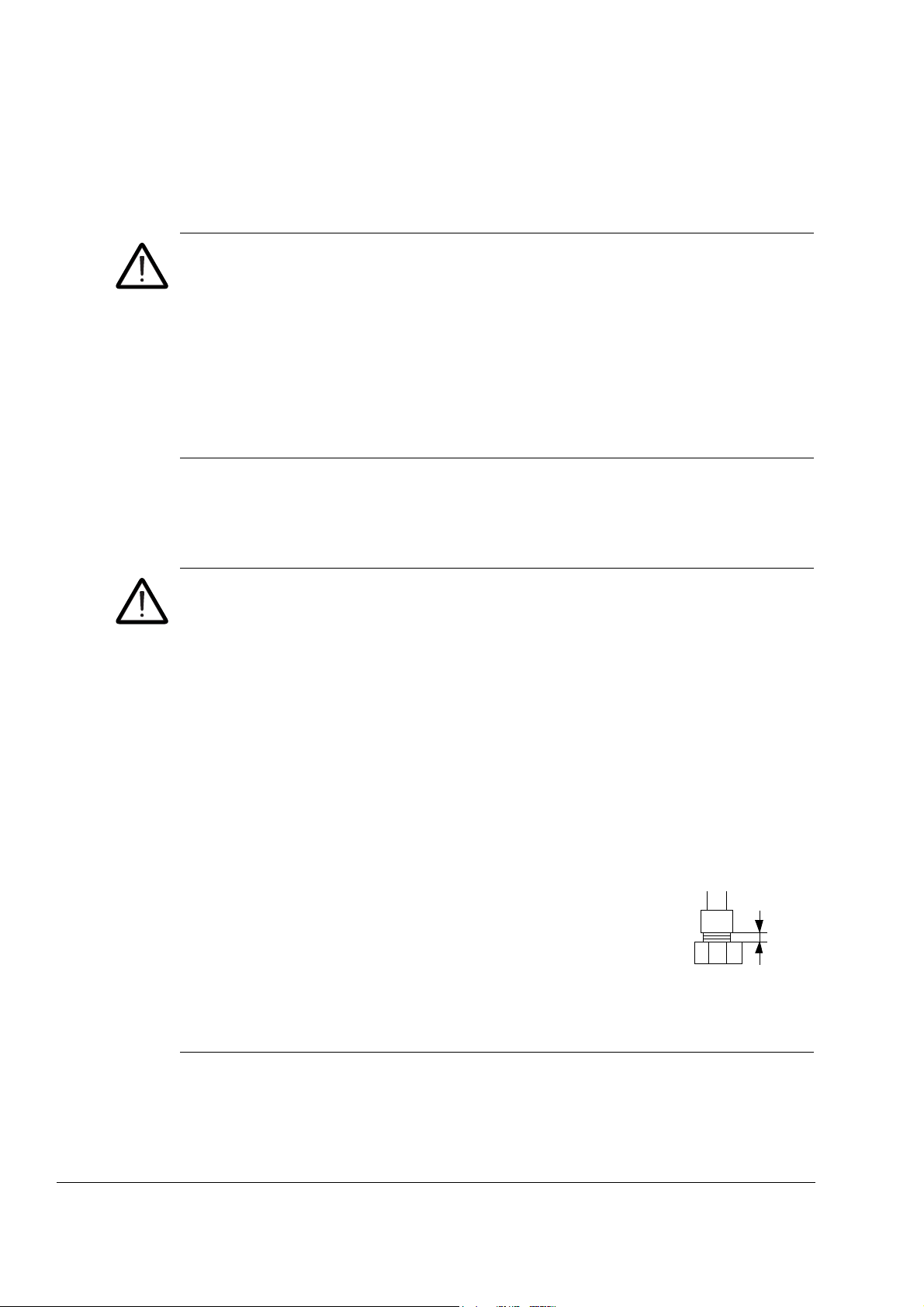
2 mm
Use of the hand-operated winch
These instructions are intended for all who use the hand-operated winch delivered
with the drive when replacing the supply or inverter modules.
WARNING! Ignoring these instructions can cause physical injury or death, or
damage the to equipment.
• Before using the winch for the first time, spool out 2 meters (6 feet) of cable, then
rewind the cable onto the drum keeping enough tension on the cable to make
sure no slack is left on the drum.
• When lowering the module, keep in mind that any slack on the winch may cause
the module to suddenly drop for several centimetres.
• After using the winch, rewind the cable onto the drum keeping enough tension on
the cable to make sure no slack is left on the drum.
Work on the liquid cooling system
These instructions are intended for all who are responsible for installation and
maintenance work of the liquid cooling system of the drive.
WARNING! Ignoring the following instructions can cause physical injury or damage
to the equipment:
• Beware of hot liquid. Do not work on the liquid cooling system until the pressure is
lowered down by stopping the pumps. High-pressure warm coolant (6 bar, max.
50°C) is present in the internal cooling circuit when it is in operation.
• Before power switch-on, make sure that the internal cooling circuit is filled up with
coolant. Running the pump dry will damage it. Also the drive will not cool down.
• Units with a liquid cooling unit option (+C199, +C140, +C141): Do not open
the pump inlet or outlet valves before filling up the internal cooling circuit. The
pumps are prefilled with a water-glycol-inhibitor mixture to prevent corrosion and
the valves are closed at the factory.
• Avoid skin contact with coolant, especially antifreeze. Do not syphon them by
mouth. If such substance is swallowed or gets into the eyes, seek medical advice.
• Do not overtighten the outer union of the nuts of the liquid
hoses - leave 2 to 3 mm of thread visible. Overtightening will
break the hose.
• Drain the unit before storing in temperatures below 0°C.
Freezing of the liquid cooling system is not allowed. If the ambient temperature is
below +5°C, add antifreeze and corrosion inhibitors to the cooling liquid.
Operation at temperatures below zero is not permitted, not even with antifreeze.
Safety instructions
Safe start-up and operation
General safety
These warnings are intended for all who plan the operation of the drive or operate
the drive.
WARNING! Ignoring the following instructions can cause physical injury or death or
damage the equipment:
• Before adjusting the drive and putting it into service, make sure that the motor
and all driven equipment are suitable for operation throughout the speed range
provided by the drive. The drive can be adjusted to operate the motor at speeds
above and below the speed provided by connecting the motor directly to the
power line.
• Do not activate automatic fault reset functions of the drive control program if
dangerous situations can occur. When activated, these functions will reset the
drive and resume operation after a fault.
• Do not control the motor with the disconnecting device (means); instead, use the
control panel keys and , or commands via the I/O board of the drive. The
maximum allowed number of charging cycles of the DC capacitors ie, power-ups
by applying power, is five in ten minutes.
19
• Do not use the Prevention of unexpected start function or Safe torque off function
for stopping the drive when the inverter unit(s) is running. Give a Stop command
instead.
Note:
• If an external source for start command is selected and it is ON, the drive (with
Standard Control Program) will start immediately after fault reset unless the drive
is configured for 3-wire (a pulse) start/stop.
• When the control location is not set to Local (L not shown in the status row of the
display), the stop key on the control panel will not stop the drive. To stop the drive
using the control panel, press the LOC/REM key and then the stop key .
Permanent magnet motor drives
These are additional warnings concerning permanent magnet motor drives.
WARNING! Do not run the motor above the rated speed. Motor overspeed leads to
overvoltage which may result in explosion of the capacitors in the intermediate circuit
of the drive.
Safety instructions

20
Safety instructions

Introduction to the manual
What this chapter contains
This chapter describes the intended audience and contents of the manual. It
contains a flowchart of steps in checking the delivery, installing and commissioning
the drive. The flowchart refers to chapters/sections in this manual and other
manuals.
Applicability
This manual applies to the hardware of the ACS800-17LC drives. For the firmwares
and optional devices, see the appropriate manuals.
Target audience
This manual is intended for people who plan the installation, install, commission, use
and service the drive. Read the manual before working on the drive. You are
expected to know the fundamentals of electricity, wiring, electrical components and
electrical schematic symbols.
21
Contents
The manual is written for readers worldwide. Both SI and imperial units are shown.
The chapters of this manual are briefly described below.
Safety instructions gives safety instructions for the installation, commissioning,
operation and maintenance of the drive.
Introduction to the manual introduces the manual.
Hardware description describes the operation principle and construction of the drive.
Mechanical installation instructs how to move, place and mount the drive.
Planning the electrical installation provides advice on motor and cable selection, the
protective functions of the drive, and cable sizes and routing.
Electrical installation instructs the electrical of the drive.
Installation checklist helps in checking the mechanical and electrical installation of
the drive.
Maintenance contains preventive maintenance instructions.
Fault tracing contains troubleshooting instructions.
Introduction to the manual
22
Technical data contains the technical specifications of the drive eg, ratings, frame
sizes and technical requirements and provisions for fulfilling the requirements for CE
and other markings.
Dimensions contains information on the dimensions of the drive.
Related documents
See the List of related manuals on the inside of the front cover.
Categorization by frame size and option code
The instructions, technical data and dimensional drawings which concern only
certain drive frame sizes are marked with the symbol of the frame size (such as
“2×R8i+2×R8i”, etc.). The frame size is not marked on the drive designation label. To
identify the frame size of your drive, see section Type equivalence table on page
147.
The instructions and technical data which concern only certain optional selections
are marked with option codes eg, +E202.
The options included in the drive can be identified from the option codes visible on
the type designation label. The option selections are listed in section Type
designation key on page 50.
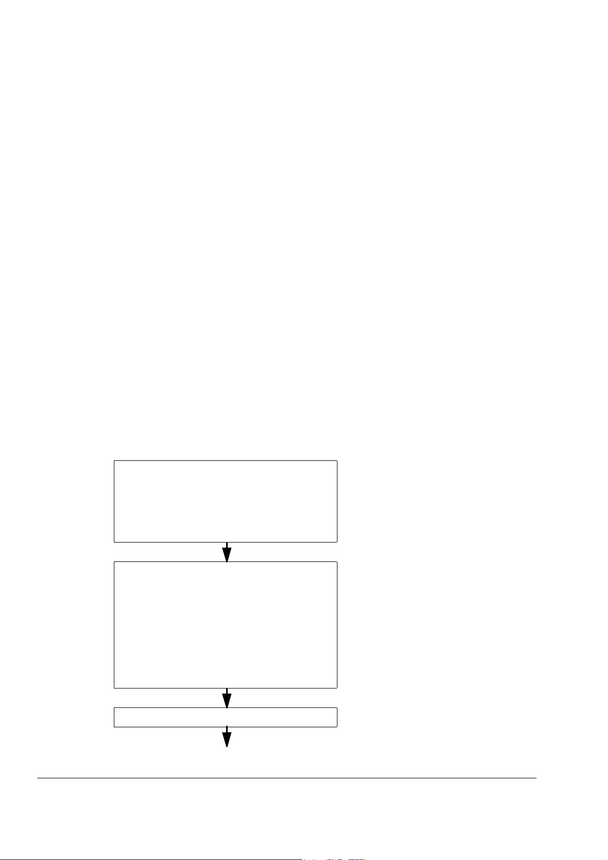
Quick installation and start-up flowchart
Task See
Plan the installation.
Check the ambient conditions, ratings, required
external cooling arrangements, input power
connection, compatibility of the motor, motor
connection, and other technical data.
Select the cables.
Unpack and check the units.
Check the type code indicated by the type
designation label with the original order. If the drive is
about to be connected to an IT (ungrounded) system,
check that the drive is not equipped with EMC filtering
+E202. Check that all necessary optional modules
and equipment are present and correct.
Only intact units may be started up.
Check the installation site. Checking the installation site, page 55
Technical data, page 145
Planning the electrical installation, page 69
Option manuals (if optional equipment is
included)
Mechanical installation, page 55
Hardware description, page 27
For instructions on how to disconnect the EMC
filtering, contact your local ABB representative.
If the drive has been non-operational for more
than one year, the drive DC link capacitors
need to be reformed. Contact your local ABB
representative for more information.
Introduction to the manual
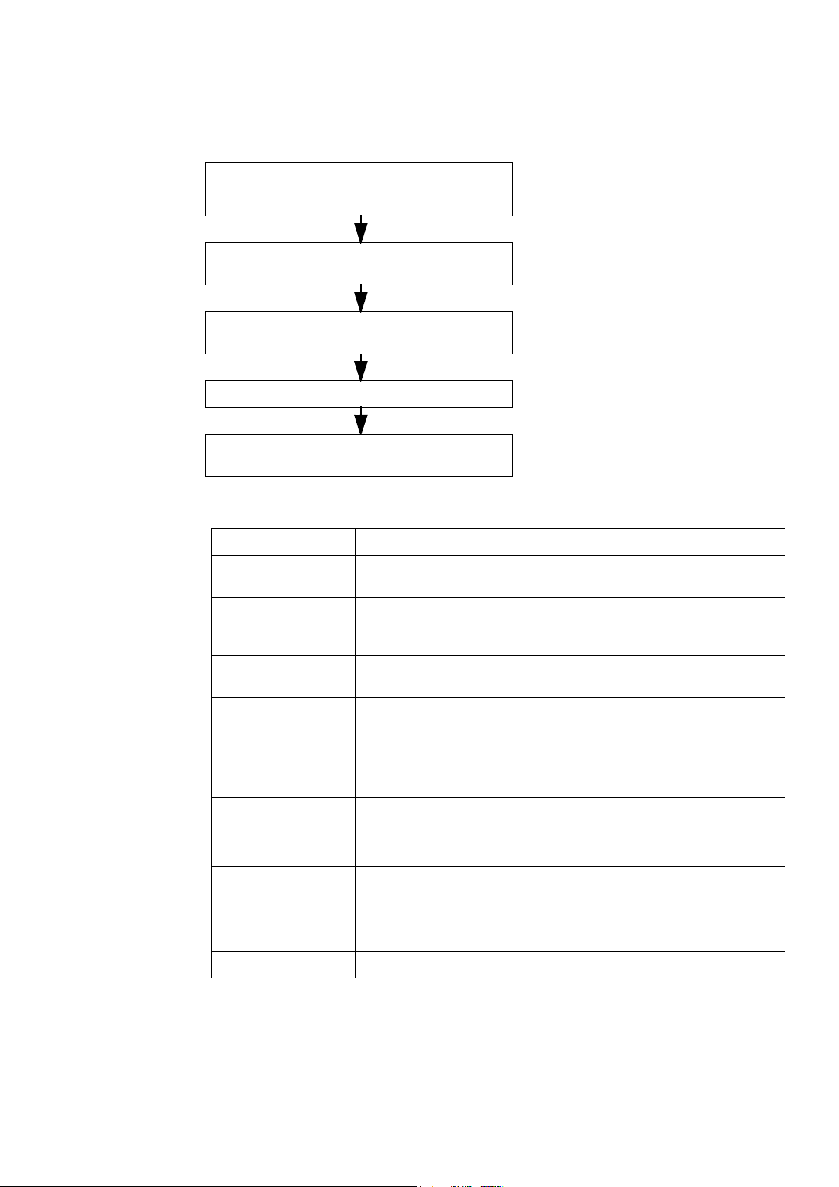
Task See
Route the cables. Routing the cables, page 80
Mount the cabinet line-up. Mechanical installation, page 55
23
Check the insulation of the motor and the motor
cable.
Connect the power cables. Connect the control and
the auxiliary control cables.
Check the installation. Installation checklist, page 109
Start up the drive. Start-up, page 111 and appropriate firmware
Terms and abbreviations
Term/Abbreviation Explanation
AGPS Gate driver power supply board. An optional board within drives, used to
APBU Optical branching unit for fiber links that use the PPCS protocol. The unit
Checking the insulation of the assembly, page
91
Electrical installation, page 91
manual
implement the Prevention of unexpected start function.
is used for connecting parallel-connected supply and inverter modules to
the RDCU.
ASTO Safe torque off board. An optional board used to implement the Safe
torque off function.
Brake chopper Conducts the surplus energy from the intermediate circuit of the drive to
the brake resistor when necessary. The chopper operates when the DC
link voltage exceeds certain maximum limit. The voltage rise is typically
caused by deceleration (braking) of a high inertia motor.
Brake module Brake chopper enclosed inside a metal enclosure. See Brake chopper.
Brake resistor Dissipates the drive surplus braking energy conducted by the brake
chopper to heat. Essential part of the brake circuit. See Brake chopper.
CMF Common mode filtering
Common motor
terminal cubicle
DDCS Distributed drives communication system; a protocol used in optical fiber
EMC Electromagnetic compatibility
Cubicle with the busbars for the motor cable connection
communication inside and between ABB drives.
Introduction to the manual
24
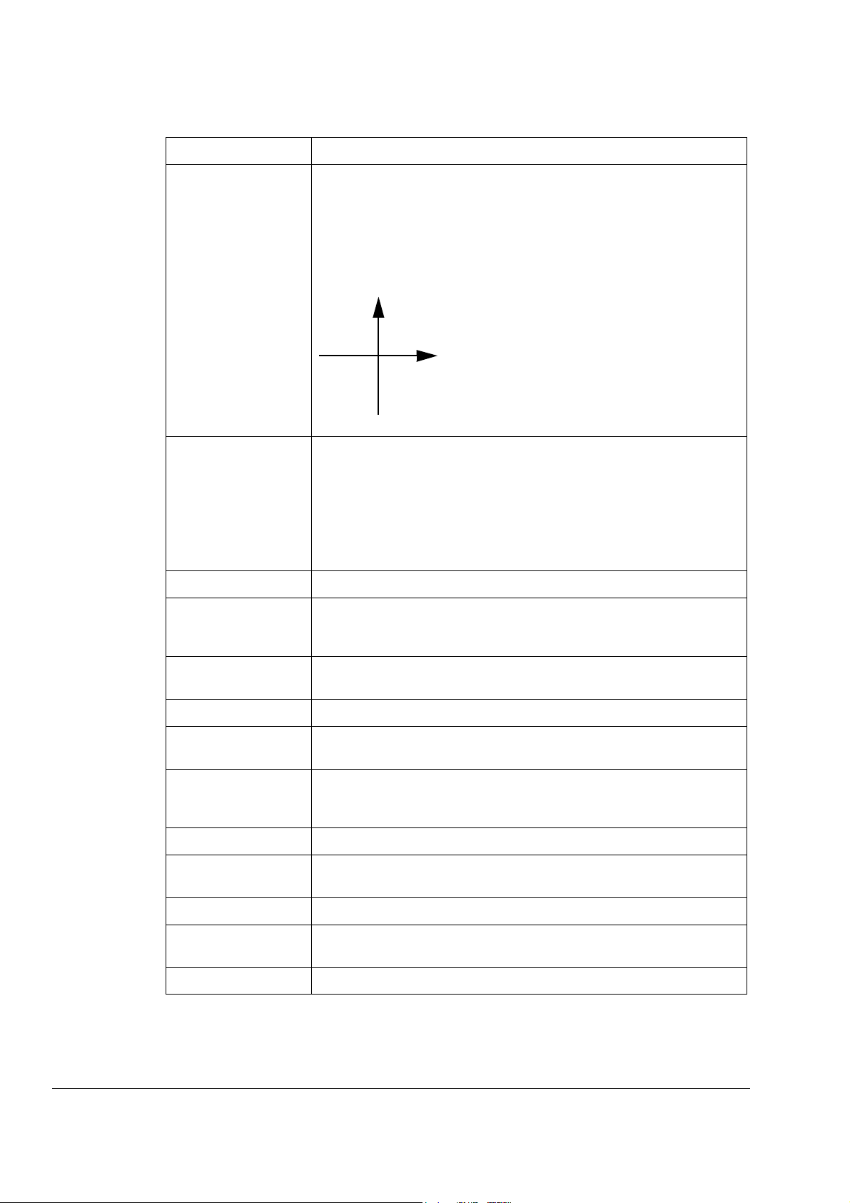
Speed
Torque
I
IVIII
II
Term/Abbreviation Explanation
Four-quadrant
operation
Frame (size) Refers to power modules that share a similar mechanical construction, for
IGBT Insulated gate bipolar transistor
Operation of a machine as a motor or generator in quadrants I, II, III and
IV as shown below. Also used as an attribute of a drive; a regenerative
drive can operate the electric machine in all four quadrants, a nonregenerative only in two. In quadrants I and III, the machine operates as a
motor, whereas in quadrants II and IV it operates as a generator
(regenerative braking).
example:
• inverter modules of frame R8i
• frame 2×R8i + 2×R8i includes two size R8i supply modules and two R8i
inverter modules.
To determine the frame size of a component, refer to section Type
equivalence table on page 147..
IGBT supply module Bidirectional IGBT bridge and related components enclosed inside a metal
enclosure. Used as the supply module in regenerative and low-harmonic
drives.
IGBT supply unit (ISU) IGBT supply modules under control of one control board, and related
components. See IGBT supply module.
Inverter Converts direct current and voltage to alternating current and voltage.
Inverter module Inverter bridge, related components and drive DC link capacitors enclosed
inside a metal enclosure.
Inverter unit (INU) Inverter module(s) under control of one control board, and related
components. One inverter unit typically controls one motor. See Inverter
module.
LCL filter Inductor-capacitor-inductor filter for attenuating harmonics
PPCS Power plate communication system; a protocol used in the optical fiber
link that controls the output semiconductors of a power module.
RAPI Auxiliary power interface board.
RDCU Drive control unit. The RDCU is a separate unit consisting of an RMIO
board built in a plastic housing.
RFI filter Radio-Frequency Interference filter.
Introduction to the manual
 Loading...