


410
Table of contents
 Loading...
Advant
®
OCS
with Master software
Advant Controller 410
Version 1.5/2
Product Guide
3BSE 015 966R201 Rev B

3BSE 015 966R201 Rev B
3BSE001264/E
Template: 3BSE001286/E
Use of DANGER, WARNING, CAUTION, and NOTE
This publication includes, DANGER, WARNING, CAUTION, and NOTE information where appropriate to point out safety
related or other important information.
DANGER Hazards which could result in severe personal injury or death
WARNING Hazards which could result in personal injury
CAUTION Hazards which could result in equipment or property damage
NOTE Alerts user to pertinent facts and conditions.
Although DANGER and WARNING hazards are related to personal injury, and CAUTION hazards are associated with
equipment or property damage, it should be understood that operation of damaged equipment could, under certain operational
conditions, result in degraded process performance leading to personal injury or death. Therefore, comply fully with all
DANGER, WARNING, and CAUTION notices.
TRADEMARKS
Master, MasterPiece, MasterView and MasterAid are registered trademarks of ABB Ltd MasterNet, MasterBus, and
MasterBatch are trademarks of ABB A sea Brown Bo veri Ltd. Advan t, AdvaComman d, AdvaIn form, AdvaB uild, AdvaS oft and
AdvaControl are reg. trademarks of ABB Process Automation Corp. HART is a trademark of HART Communication
Foundation. Echelon, LON, LonTalk, L
ONWORKS, LONMARK, and Neuron are registered trademarks of Echelon Corporation.
HP and all HP-products are registered trademarks of Hewlett-Packard Company. IBM and all IBM-products are trademarks of
International Business Machines Corporation. KERMIT is copyright 1985, Trustees of Colombia University. Lotus 1-2-3 is a
trademark of Lotus Development Corporation. MATLAB is a registered trademark of The MathWorks Inc, USA. MODBUS is a
registered trademark of GOULD Electronics. MOTIF and OSF are trademarks of Open Software Foundation. MS-DOS,
Microsoft, Microsoft Excel, and Word for Windows are registered trademarks of Microsoft Corporation. Postscript is a
registered trademark of Adobe Systems Inc.
PROFIBUS and PROFIBUS-DP are trademarks of Profibus International (P.I.).
Siemens and all Siemens-products mentioned in this publication are trademarks of Siemens AG. UNIX is a registerd trademark
of AT&T Corporation. VAX, VMS, Digital, DEC, VT100 - VT420 are trademarks of Dig ital Eqipmen t Corporat ion. X-window
Systems is a trademark of Massachusetts Institute of Technology. All rights to other Trademarks reside with their respective
owners.
NOTICE
The information in this document is subject to change without notice and should not be construed as a commitment by ABB
Automation Products AB. ABB Automation Products AB as sumes no responsibility for any errors that may appear in this
document.
In no event shall ABB Automation Products AB be liable for direct, indirect, special, incidental or consequential damages of
any nature or kind arising from the use of this document, nor shall ABB Automation Products AB be liable for incidental or
consequential damages arising from use of any software or hardware described in this document.
This document and parts thereof must not be rep roduced or cop ied without ABB Auto mation Produ cts AB’s written permission,
and the contents thereof must not be imparted to a third party nor be used for any unauthorized purpose.
The software described in this document is furnished under a license and may be used, copied, or disclosed only in accordance
with the terms of such license.
CE MARKING
This product meets the requirements specified in EMC Directive 89/336/EEC and in Low Voltage Directive 72/23/EEC.
Copyright © ABB Automation Products AB 2001

Advant Controller 410 Product Guide
Table of Contents
3BSE 015 966R201 Rev B i
TABLE OF CONTENTS
Chapter 1 - Overview
1.1 Product Benefits.................................................................................. ..... ...... .......... 1-1
1.2 Features....................................................................................................................1-2
Chapter 2 - Functional Description
2.1 General Controller Utilities ..................................................................................... 2-1
2.1.1 CPU......................................................................................................... 2-1
2.1.2 Memory and Backup.............................. ..... ...... ...................................... 2-1
2.1.3 System Clock, External Clock Synchronization ..................................... 2-2
2.1.4 Configuration.......................................................................................... 2-2
2.1.5 Execution................................................................................................2-2
2.1.6 Start-up....................................................................................................2-3
2.2 Process Control........................................................................................................ 2-3
2.3 I/O System Support................................................. ............................................. ....2-5
2.4 Time Tagging of Events and Alarms....................................................................... 2-5
2.5 Pulse Counting and Positioning............................................................................... 2-5
2.6 Switchgear Integration............................................................................................. 2-6
2.7 Drives Integration.................................................................................................... 2-6
2.8 Variable Speed Drive Control..................................................................................2-7
2.9 Communication........................................................................................................ 2-7
2.10 AdvaCommand Support .......................................................................................... 2-8
2.11 Local Operator Station MasterView 320 ................................................................. 2-9
2.12 Local Printer .......................................................................................................... 2-10
2.13 Scope of Controller Functions...............................................................................2-10
Chapter 3 - Software Components
3.1 Overview.................................................................................................................. 3-1
3.2 Basic Program Module, QC01-BAS11....................................................................3-1
3.3 Optional Program Module, QC01-LIB11................................................................ 3-4
3.4 Optional Program Module, QC01-LIB12................................................................ 3-5
3.5 Optional Program Module, QC01-OPF11...............................................................3-6
3.6 Optional Program Module, QC01-LOS11............................................................... 3-6
3.7 Optional Program Module, QC01-BAT11...............................................................3-6
3.8 Optional Program Module, QC01-UDP11 .............................................................. 3-6

Advant Controller 410 Product Guide
Table of Contents
ii 3BSE 015 966R201 Rev B
CONTENTS (continued)
Chapter 4 - Hardware Components
4.1 Processor Module.....................................................................................................4-1
4.2 Program Card...........................................................................................................4-3
4.3 Submodule Carriers..................................................................................................4-3
4.4 Submodules..............................................................................................................4-3
4.5 Subrack.....................................................................................................................4-4
4.6 System Unit........................................... ...... ............................................. ...... ..... .....4-5
4.7 I/O Systems..............................................................................................................4-5
4.8 Communication........................................................................................................4-5
4.8.1 Control Network......................................................................................4-6
4.8.2 Fieldbus Communication................. ............................................. ..... .....4-6
4.8.3 External Communication ......................................................................4-10
4.8.4 Telecontrol & SPA Bus .........................................................................4-11
4.9 Power Supply System ............................................................................................4-11
4.9.1 Mains Network Types ...........................................................................4-12
4.9.2 Redundancy, Mains Power Supply .......................................................4-12
4.9.3 Configuration Alternatives....................................................................4-12
4.10 ESD Protection.......................................................................................................4-13
4.11 CE marked equipment............................................................................................4-13
Chapter 5 - Mechanical Design
5.1 Cabinet Design.........................................................................................................5-1
5.2 Product Design.........................................................................................................5-2
5.2.1 Standard Version of Advant Controller 410............................................5-2
5.2.2 Compact Version of Advant Controller 410............................................5-4
Chapter 6 - Technical Data and Performance
6.1 PC Program..............................................................................................................6-1
6.2 I/O Signals................................................................................................................6-1
6.3 I/O Boards................................................................................................................6-2
6.3.1 Connection Unit Dimensions.................................................. ...... ..........6-3
6.4 Functional Units.................................................................................................. .....6-4
6.5 Communication........................................................................................................6-5
6.5.1 Data Set and Text Set..............................................................................6-5
6.5.2 Data Set Peripheral (DSP).......................................................................6-5
6.5.3 Communication buses.............................................................................6-5

Advant Controller 410 Product Guide
Table of Contents
3BSE 015 966R201 Rev B iii
CONTENTS (continued)
6.6 Time Synchronization..............................................................................................6-7
6.7 Time Tagging of Events (Alarms)...........................................................................6-7
6.8 Trend Data Storage..................................................................................................6-8
6.9 CPU Load Calculation.............................................................................................6-9
6.9.1 CPU Load from Data Set Communication............................................6-11
6.9.2 CPU Load from Data Set Peripheral Communication...........................6-11
6.10 Read/Write Memory (RAM) Requirements .......................................................... 6-12
6.11 Program Module Size on Program Card................................................................ 6-14
6.12 Controller Subrack.................................................................................................6-15
6.13 Cabinet RM500....................................................... ..... ..........................................6-15
6.13.1 Mounting Bars for Connection Units.................................................... 6-16
Chapter 7 - Environmental Immunities
7.1 Environmental Considerations............................................................................. ....7-1
Chapter 8 - Ordering
8.1 Price List Structure .................................................................................................. 8-1
8.2 Basic Software License...................................................... ......................................8-1
8.3 Assembled Delivery or Loose Part Delivery ........................................................... 8-2
8.4 Loose Part Delivery and CE-marking......................................................................8-2
8.5 Non Standard Program Modules.............................................................................. 8-2
8.6 Heat Exchanger........................................................................................................8-2
8.7 Reference Guide for standard Advant Controller 410............................................. 8-3
8.7.1 General Requirements............................................................................. 8-3
8.7.2 System Units........................................................................................... 8-3
8.7.3 Software Licenses...................................................................................8-4
8.7.4 Software Options.................................................................................... 8-4
8.7.5 Special Applications............................................................................... 8-5
8.7.6 System Software Back-up Card.................................................... ...... ....8-6
8.7.7 Hardware Options ..................................................................................8-6
8.7.8 Communication....................................................................................... 8-7
8.7.9 Printers.................................................................................................. 8-12
8.7.10 Power Supply System ............... ............................................. ...... ...... ..8-13
8.7.11 S100 I/O System................................................................................... 8-17
8.7.12 Cabinets ................................................................................................ 8-26
8.7.13 Documentation......................................................................................8-27
8.7.14 Software Utilities.................. ................................................................ 8-32

Advant Controller 410 Product Guide
Table of Contents
iv 3BSE 015 966R201 Rev B
CONTENTS (continued)
8.8 Reference Guide for Compact Version of AC 410.................................................8-32
8.8.1 System Units .......................................................................................8-32
8.8.2 Software Licenses.................................................................................8-33
8.8.3 Software Options ..................................................................................8-33
8.8.4 Special Applications..............................................................................8-33
8.8.5 System Software Back-up Card ............................................................8-34
8.8.6 Hardware Options.................................................................................8-35
8.8.7 Communication.....................................................................................8-35
8.8.8 Documentation......................................................................................8-41
8.8.9 Software Utilities ..................................................................................8-44

Advant Controller 410 Product Guide
Table of Contents
3BSE 015 966R201 Rev B v
ILLUSTRATIONS
Figure 1-1. Advant Controller 410 with S100 I/O.......................................................... 1-1
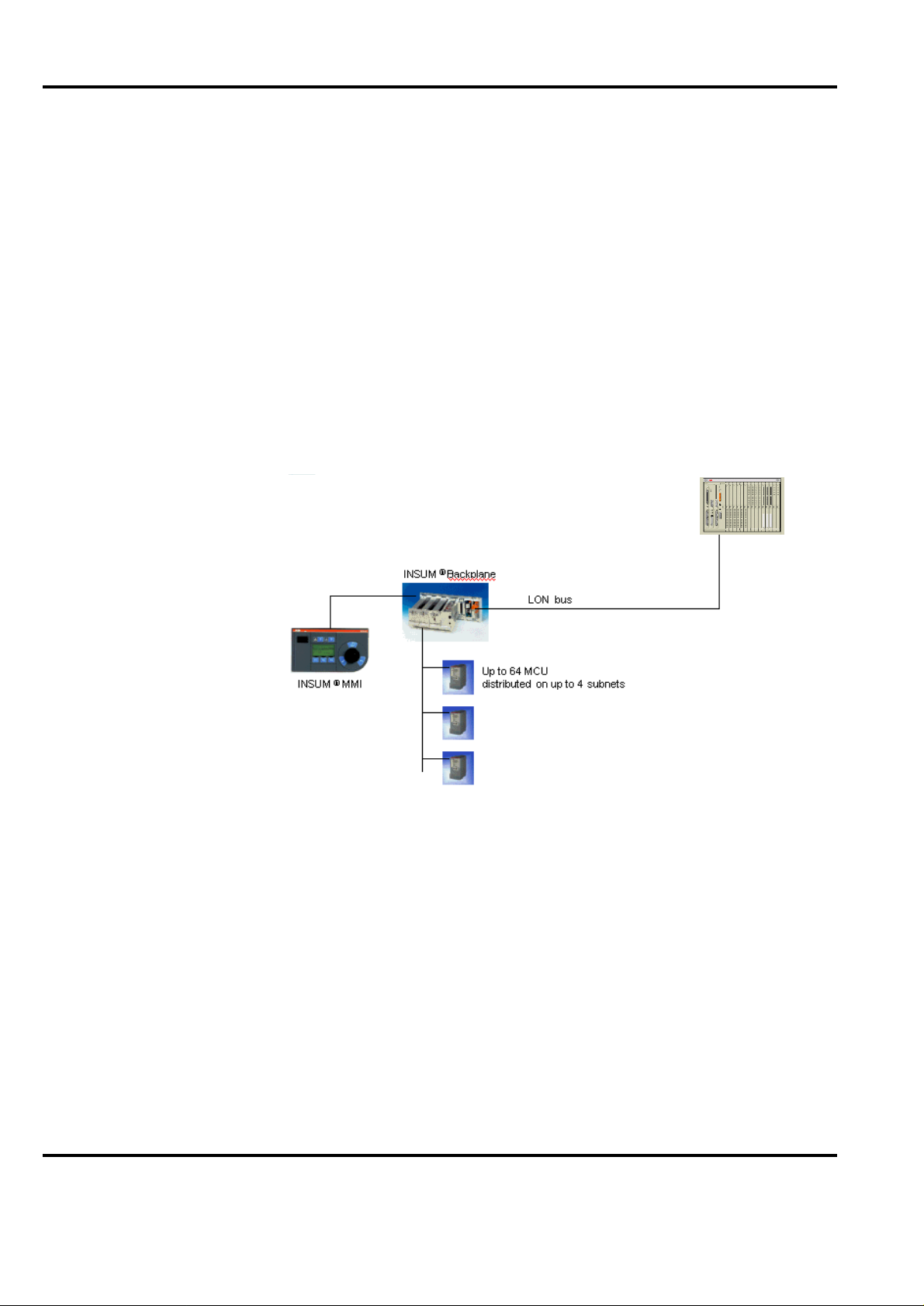
Figure 2-1. AC 400 Series configuration with INSUM Motor Controller......................2-6
Figure 2-2. AC 400 Series configuration with drive....................................................... 2-7
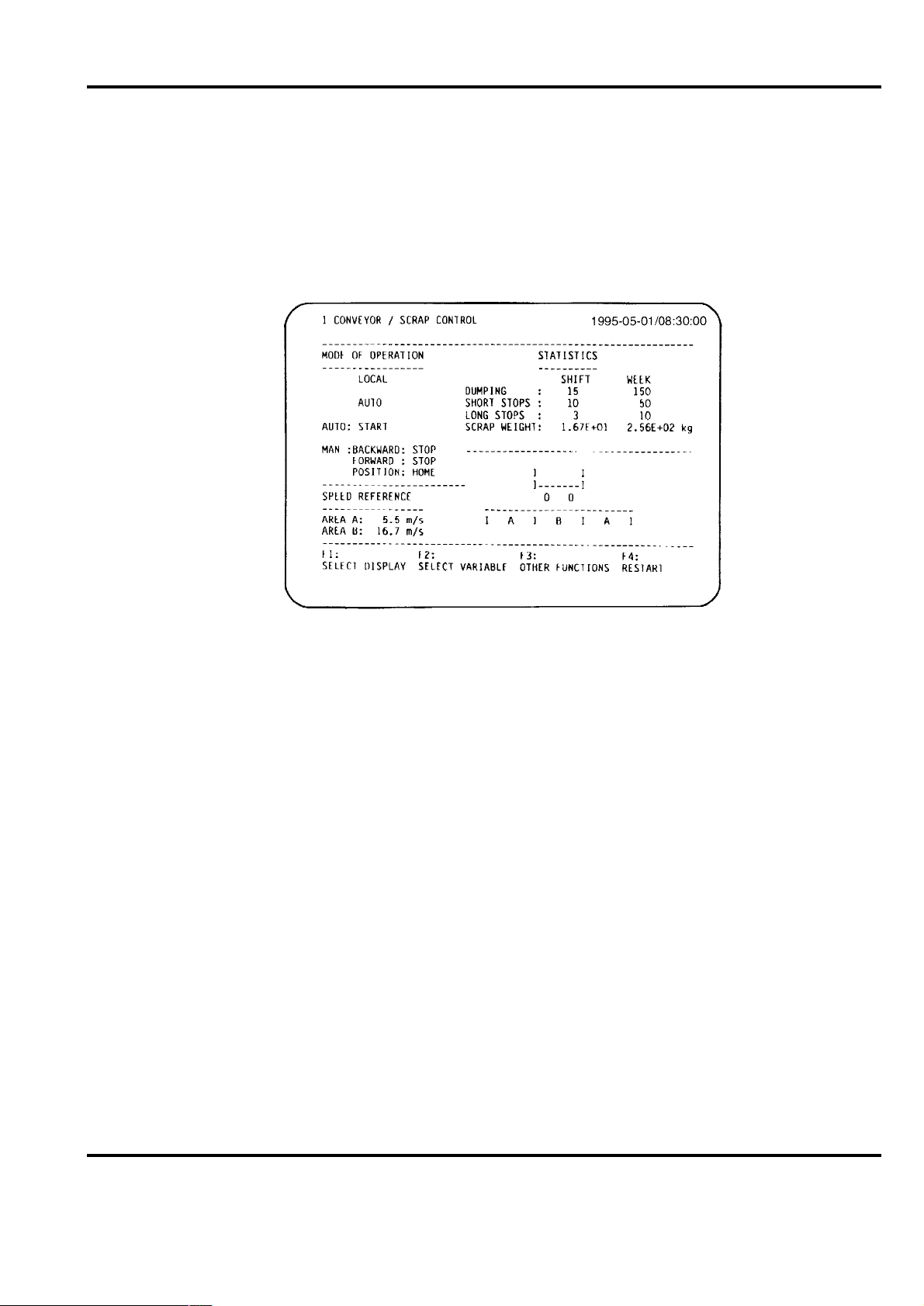
Figure 2-3. Example of display from MasterView 320................................................... 2-9
Figure 4-1. Front View of the PM150V Processor Module............................................4-2
Figure 4-2. The processor module, PM150V, within the S100 I/O subrack...................4-4
Figure 4-3. MasterBus 300/300E connected to Advant Controller 410..........................4-6
Figure 4-4. Advant Fieldbus 100 using Coaxial Media connected to
Advant Controller 410................................................................................. 4-6
Figure 4-5. Advant Fieldbus 100 using Twisted Pair Media connected to
Advant Controller 410.................................................................................. 4-7
Figure 4-6. Advant Fieldbus 100 using Media Redundancy connected to
Advant Controller 410.................................................................................. 4-7
Figure 4-7. Advant Fieldbus 100 using Bus Redundancy connected to
Advant Controller 410................................................................................. 4-8
Figure 4-8. RCOM/RCOM+ connected to Advant Controller 410................................. 4-8
Figure 4-9. PROFIBUS-DP connected to Advant Controller 410.................................. 4-9
Figure 4-10. LONWORKS connected to Advant Controller 410..................................... 4-9
Figure 4-11. MasterFieldbus connected to Advant Controller 410................................. 4-10
Figure 4-12. EXCOM connected to Advant Controller 410........................................... 4-10
Figure 4-13. MultiVendor Interface connected to Advant Controller 410......................4-10
Figure 4-14. GCOM connected to Advant Controller 410...............................................4-11
Figure 4-15. Telecontrol and SPA Bus connected to Advant Controller 410..................4-11
Figure 4-16. Block diagram of power supply without redundancy................................. 4-13
Figure 4-17. Block diagram of power supply with redundancy.................................... ..4-13
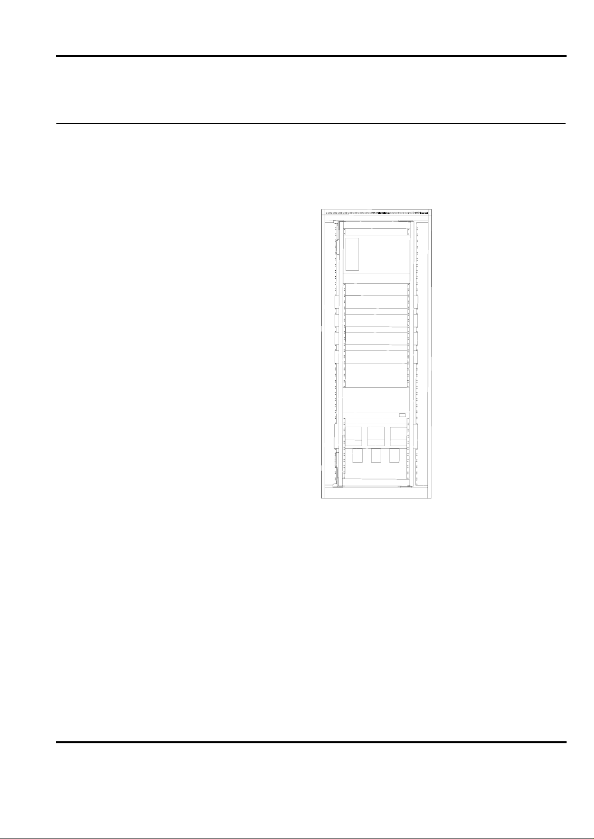
Figure 5-1. Typical Cabinet Configuration, Redundant Power Supply.......................... 5-1
Figure 5-2. Maximum cabinet configuratio n for Advan t Controller 410 with
S100 I/O assembled in RM500V1 cabinets.................................................. 5-2
Figure 5-3. Cabinet configuration for Advant Controller 410 assembled in RM500V2
cabinets......................................................................................................... 5-3
Figure 5-4. Compact version of Advant Controller 410 .................................................5-4
Figure 5-5. The size of the compact version of the Advant Controller 410.................... 5-5
Figure 6-1. The division of the I/O subrack.................................................................. 6-15

Advant Controller 410 Product Guide
Table of Contents
vi 3BSE 015 966R201 Rev B

Advant Controller 410 Product Guide
Table of Contents
3BSE 015 966R201 Rev B vii
TABLES
Table 2-1. S800 I/O modules supported by Advant Controller 410..............................2-5
Table 2-2. Functions and configuration alternatives for Advant Controller 410......... 2-10
Table 3-1. PC elements in the basic program module QC01-BAS11............................ 3-2
Table 3-2. Functional units in the base program module QC01-BAS11....................... 3-3
Table 3-3. Additional PC elements in program module QC01-LIB11.......................... 3-4
Table 3-4. Additional PC elements in program module QC01-LIB12.......................... 3-5
Table 3-5. Functional units in the program module QC01-LIB12 ................................ 3-5
Table 4-1. Submodules.................................................................................................. 4-3
Table 4-2. System unit with single voltage regulator....................................................4-5
Table 4-3. System unit with redundant voltage regulator.............................................. 4-5
Table 4-4. Different power supply arrangements for Advant Controller 410 with
S100 I/O.....................................................................................................4-12
Table 5-1. RM500V1 configurations for Advant Controller 410 with S100 I/O .......... 5-3
Table 5-2. RM500V2 configurations for Advant Controller 410 with S100 I/O .......... 5-3
Table 6-1. The I/O limits of Advant Controller 410......................................................6-1
Table 6-2. The max. I/O configuration of Advant Controller 410.................................6-2
Table 6-3. The Width of the Connection Units.............................................................. 6-3
Table 6-4. The functional units limits of Advant Controller 410 ..................................6-4
Table 6-5. Number of buses/channels that can be connected to Advant Controller 4106-5
Table 6-6. Submodules that are possible to mount into the processor module.............. 6-6
Table 6-7. Relative time errors between events (DI signals).........................................6-8
Table 6-8. Data logging capabilities.............................................................................. 6-8
Table 6-9. Execution times............................................................................................ 6-9
Table 6-10. Examples of CPU load ............................................................................... 6-10
Table 6-11. The CPU load caused by data set communication......................................6-11
Table 6-12. T he CPU load caused by data set peripheral communication (cycle time of scan
task = 512 ms) .............................................................................................6-11
Table 6-13. Calculation of RAM Requirement.............................................................. 6-12
Table 6-14. Program module memory area on program card ........................................ 6-14
Table 6-15. The no. of slots in the I/O subrack ............................................................. 6-15
Table 6-16. RM500 cabinets dimensions....................................................................... 6-15
Table 6-17. RM500 cabinet protection classes..............................................................6-16
Table 6-18. Numbers of mounting bars in RM500V1 cabinets.....................................6-16
Table 6-19. Numbers of mounting bars in RM500V2 cabinet ......................................6-17
Table 8-1. General and Normative Requirements.........................................................8-3
Table 8-2. System Units................................................................................................. 8-3
Table 8-3. Processor Modules........................................................................................ 8-4
Table 8-4. AdvaControl Basic Functions and Incremental Licenses............................. 8-4

Advant Controller 410 Product Guide
Table of Contents
viii 3BSE 015 966R201 Rev B
Table 8-5. Optional Standard Program Modules ...........................................................8-4
Table 8-6. Optional Program Modules for Special Applications...................................8-5
Table 8-7. Telecontrol & SPA Bus.................................................................................8-5
Table 8-8. System Software Back-up Card....................................................................8-6
Table 8-9. Pr ogram Card Interface and back-up flash-PROMs.....................................8-6
Table 8-10. Free-programmable Module .........................................................................8-6
Table 8-11. MasterBus 300 and MasterBus 300E............................................................8-7
Table 8-12. G COM ..........................................................................................................8-7
Table 8-13. Advant Fieldbus 100 for coaxial cable ........................................................8-8
Table 8-14. Advant Fieldbus 100 for twisted pair cable.................................................8-8
Table 8-15. Modems for Advant Fieldbus 100................................................................8-8
Table 8-16. MasterFieldbus..............................................................................................8-9
Table 8-17. Details for MasterFieldbus............................................................................8-9
Table 8-18. Details for PROFIBUS-DP.........................................................................8-10
Table 8-19. Details for LON WORKS Network............................................................8-10
Table 8-20. Connection of MasterView 320, Printer and Excom..................................8-10
Table 8-21. Multi Vendor Interfaces ..............................................................................8-10
Table 8-22. Miscellaneous Communication Equipment................................................8-11
Table 8-23. P rinters........................................................................................................8-12
Table 8-24. Power Supply in RM500V1 Cabinet..........................................................8-13
Table 8-25. Power Supply in RM500V2 Cabinet..........................................................8-14
Table 8-26. Extra Power Supply for Field equipment ...................................................8-15
Table 8-27. Miscellaneous Power Supply Equipment................................................... 8-16
Table 8-28. Mains Supply Filter ....................................................................................8-16
Table 8-29. A nalog Input Sets for S100 I/O ..................................................................8-17
Table 8-30. Redundant Analog Input Sets for S100 I/O................................................8-18
Table 8-31. Analog Output Sets for S100 I/O................................................................8-18
Table 8-32. Analog Input/Output Sets for S100 I/O......................................................8-18
Table 8-33. Redundant Analog Input/Output Sets for S100 I/O....................................8-19
Table 8-34. Pulse Input and Positioning Sets for S100 I/O ...........................................8-19
Table 8-35. Digital Input Sets for S100 I/O...................................................................8-20
Table 8-36. Digital Output Sets for S100 I/O................................................................8-21
Table 8-37. Connection of Thyristor Converters...........................................................8-22
Table 8-38. S100 I/O boards for HART Protocol Interface...........................................8-22
Table 8-39. S100 I/O for Intrinsic Safety Isolator support (without connection units) .8-23
Table 8-40. Mounting Bars for Connection Units..........................................................8-25
Table 8-41. RM500V1 Cabi nets With=800 mm (3 1.5”), Depth=512 mm (20.2”).......8-26
Table 8-42. RM500V2 Cabinets
Width=700 mm (27.6”), Depth=637 mm (25.1”), Height=2225 mm (87.6”)8-26
Table 8-43. RM500 Cabinet Accessories.......................................................................8-26

Advant Controller 410 Product Guide
Table of Contents
3BSE 015 966R201 Rev B ix
Table 8-44. Documentation ........................................................................................... 8-27
Table 8-45. Software Utilities........................................................................................ 8-32
Table 8-46. System Unit ................................................................................................ 8-32
Table 8-47. Processor Modules......................................................................................8-32
Table 8-48. Software Licenses ....................................................................................... 8-33
Table 8-49. Optional Standard Program Modules.........................................................8-33
Table 8-50. Optional Program Modules for Special Application.................................. 8-33
Table 8-51. Telecontrol and SPA Bus............................................................................ 8-34
Table 8-52. System software Back-up Card ..................................................................8-34
Table 8-53. Program Card Interface and back-up flash-PROMs...................................8-35
Table 8-54. Free-programmable Module....................................................................... 8-35
Table 8-55. MasterBus 300 and MasterBus 300E.........................................................8-35
Table 8-56. GCOM ........................................................................................................ 8-36
Table 8-57. Advant Fieldbus 100 for coaxial cable....................................................... 8-36
Table 8-58. Advant Fieldbus 100 for twisted pair cable...............................................8-37
Table 8-59. Modems for Advant Fieldbus 100.............................................................. 8-37
Table 8-60. MasterFiel dbus ...........................................................................................8-38
T able 8-61. Details for PROFIBUS-DP.........................................................................8-38
T able 8-62. Details for LONWORKS Network .................................................... ...... ..8-38
Table 8-63. Connection of MasterView 320, Printer and Excom..................................8-38
Table 8-64. Multi Vendor Interfaces.............................................................................. 8-39
Table 8-65. Miscellaneous Communication Equipment................................................ 8-39
Table 8-66. Documentation on Compact version of Advant Controller 410.................8-41
Table 8-67. Software Utilities........................................................................................ 8-44

Advant Controller 410 Product Guide
Table of Contents
x 3BSE 015 966R201 Rev B
Advant Controller 410 Product Guide
Section 1.1 Product Benefits
3BSE 015 966R201 Rev B 1-1
Chapter 1 Overview
Advant Controller 410 is a medium sized process controller for binary, regulatory and
supervisory control. Its wide-ranging process control and communication capabilities make it
the right choice for medium-sized, but functionally demanding applications in industrial
environments, either standing alone o r as an integrated par t of an Advant OC S system as well as
in any other distributed control system
1.1 Product Benefits
Advant Controller 410 is a full-function process controller in a minimal hardware configuration.
You will have the latest equipment concerning functionality, interoperability and performance.
You will be able to maximize your productivity and at the same time be prepared for easy
integration of tomorrow’s technology at a reasonable cost.
Figure 1-1. Advant Controller 410 with S100 I/O

Advant Controller 410 Product Guide
Chapter 1 Overview
1-2 3BSE 015 966R201 Rev B
1.2 Features
Advant Controller 410 covers a wide range of funct i ons such as:
• Logic and sequence control.
• Data and text handling.
• Arithmetic, reporting, positioning and regulatory control.
• Highly extended flexibility and scalability - hardware as well as software.
• Self-configuration capabilit ies which makes it possible to add units while the controller is
in full operation.
• Support of a wide range of central and distribu ted I/O modules for maximum configuration
possibilities, with a maximum I/O capacity of 4300 I/O points.
• Support of local and central HMI for manual control operations, event and alarm handling,
trend curve presentation etc.
• Interoperability concerning all commun ication levels from plant floor fieldbuses to high-
speed plant network.
• Support of redundant Fieldbus Communication with Advant Fiel dbus 100.
• Support of Advant Fieldbus 100 with cable length up to 13300 meter (43300 feet).

Advant Controller 410 Product Guide
Section 2.1 General Controller Utilities
3BSE 015 966R201 Rev B 2-1
Chapter 2 Functional Description
2.1 General Controller Utilities
2.1.1 CPU
The processor module PM150V contains the total amount of RAM (Random Access Memory),
which is an 4 or 8 Mbyte dynamic RAM with error correction code. This memory holds the
system program which is in use as well as the controller system configuration and application
program, that is, all memory executed in run time. The processor module is built-up around
a microprocessor, Motorola 68020, running at 25 MHz.
The module front contains the following functions:
• Indicators and a character display for high level system diagnostics.
• The main operable equipment is a four-position rotary switch for start and working mode
selection and a restart push button.
• The module front also includes a program card interface and four slots for submodules.
• You can connect a configuration and maintenance tool on the module front.
2.1.2 Memory and Backup
System Program Backup
The system program is backed up in flash PROM and loaded to the RAM in connection to
system start. Physically , the st andard system program is stored in one program card (PCMCIA).
Normally the program card should be in place during operation. Additional program cards are
located in program card interface MB510.
Application Program Backup
The controller system configuration and the application program is normally created in an off-
line or sometimes an on-line configuration session suppo rt ed b y an engineering station.
The work is basically backed up in the en gineerin g st ation e nviro nmen t (har d d isc, flexible disc
or likely ).
To restore a RAM which has been cleared by an accident or a fatal error some measures have
to be taken, automatically and manually. In addition to the automatic loading of the system
program, described above under the heading System Program Backup , somebody has
to manually load the application program backup (including the controller system config uration)
using an engineering station.
As an alternative the Advant Controller 410 can be equipped with an optional flash card
of similar type as the one used for the system pr ogram. The flash card is contained with a DUmp
of Application Programs (DUAP) preferably taken while the controller is in the operation mode.

Advant Controller 410 Prod uct Guid e
Chapter 2 Functional Description
2-2 3BSE 015 966R201 Rev B
At need, the controller system configuration and the application program is likewise
automatically loaded from its flash card into the controller RAM. No manual intervention is
needed to get into operation after the interruption.
Flash cards are available in different memory-sizes (2, 4 or 10 Mbytes). Select a type that take
the actual application program.
The system program backup and the application pr ogram b ackup can not be mixed in one si ngle
program card.
Memory Backup Power Supply
The RAM is secured against loss of power for a minimum of four hours by a backup power
supply and battery. This is important for the configured application program, which is basically
not otherwise backed up.
If a longer backup time is desirable, you can use an application program backup (see heading
above).
2.1.3 System Clock, External Clock Synchronization
The processor module PM150V is provided with a calendar clock which is backed up by
the same battery used for memory backup. You can set the date and time from the programming
unit or from a local operator station, for example, MasterView 320. A slow, smaller adjustment
in the interval ±100 s can also be perfor med with the programming unit.
With Advant Controller 410 connected to MasterNet, as a part in a distributed control system,
the synchronization occurs automatically with other stations via a network with an accuracy
better than 3 ms.
If extreme synchronization accuracy is required between controllers (in the order of 2 ms) and
synchronization to an external clock, an external minute pulse signal can be connected to all
systems concerned.
The supervision module SB171 has a special input for external synchronization of
the calendar clock.
2.1.4 Configuration
You configure the system in accordance with the hardware and software selected, for example,
the number of I/O boards, communication lines, functional units and PC programs.
This is performed using commands from a configuration tool su ch as Advant Station 140 (with
AMPL Control Configuration 1.7 or later product versio ns ) and results in the internal
organization and activation of the data base and program areas.
2.1.5 Execution
The execution units in a PC program are normally given cycle times of 10 ms - 2 s (5 ms - 32 s
after reconfiguration). The internal program system (operating system and PC interpreter)
organizes the execution of the units with the periodicity selected, simultaneously performing
other tasks such as communication with a MasterView 320 and programming units.
Ordinarily, you can select the same cycle times for reading in values from digital and analog
boards.

Advant Controller 410 Product Guide
Section 2.1.6 Start-up
3BSE 015 966R201 Rev B 2-3
2.1.6 Start-up
The CPU front panel has a rotary switch to select start and working mode. The normal position
of the switch is 1 (AUTO). This means an automatic start when voltage is switched on or when
voltage is recovered after a power failure. At an interruption of voltage, the system stores all
the information necessary for restarting. Whether the system is to continue operations from its
status at the interruption of the voltage or if it is to be reset to zero before restart is selected with
parameters.
The different ways to start are CLEAR, STOP, AUTO or OFF LINE. The way to start is selected
on the basis of the duration of the voltage failure.
You can connect a control module which is activated when the voltage returns and which
executes one cycle to each start alternative. All start modules must belong to the same
PC program. You can define how the process is to start with these control modules.
Alarm can also be blocked at initialization of the I/O boards.
2.2 Process Control
Process control applications are programmed in the ABB Master Programming Language
(AMPL). AMPL is a function-block language with graphic representation.
The building blocks are called PC elements. There is a wide range of PC elements, from simple
AND blocks to complete PID regulators.
Besides the functional PC elements, AMPL also contains several structural elements for
dividing a PC program into suitable modules which can be managed and executed individually.
The controller can be programmed fully on-line, that is, with the program running and
controlling the process.
PC Elements
The range of ready-to-use PC elements is wide and powerful. It contains, for example,
elements for:
• Logic and Time Delays
• Sequence Control
• Data and Text Handling
• Calendar Time Functions
• Arithmetic
• Feedback Control
• Pulse counting and Frequency Measurement
• Positioning
• Reports
• Communication via Fieldbuses
The PC elements are listed under the program modules in Chapter 3, Software Components.

Advant Controller 410 Prod uct Guid e
Chapter 2 Functional Description
2-4 3BSE 015 966R201 Rev B
User Defined PC Elements
Another way to implement your frequently used control solution and ensure a fully integrated
engineering environment is to make use of the optional program module User Defined
PC Elements.
A user defined PC element appears in every sense as a standard PC element. Actually
the control solution of a user defined PC element is defined by other PC elements.
By designing your application with user defined PC elements you gain:
• Significant reductio n in tr anslation time.
• Memory saving with reuse.
• Similar documentation in Function Chart Builder and On-line Builder.
• User defined PC element hierarchy.
• Reduc ed man-hours in commissioning and mai ntenance.
Functional Units
A functional unit is a package of different functions, such as PC elements, DB elements, display
elements, dialogs and event and alarm handling. Functional units extend the power of AMPL
and supplement the PC element library for more complex control functions.
Since the functional units are ready-to-use, it simplifies documentation and implementation of
functions with both control function and associated operator’s action via display screen and
keyboard. The operator interface is always co nsistent to impr ove the operator’s interaction with
the process. Application include regulators, sequence control and motor/valve controls.
PC elements and functional units can be used freely together.
The functional units are listed under the program modules in Chapter 3, Software Components

Advant Controller 410 Product Guide
Section 2.3 I/O System Support
3BSE 015 966R201 Rev B 2-5
2.3 I/O System Support
S100 I/O System
S100 I/O boards (up to 15 boards) are located in the same subrack as the CPU. For further
information about S100 I/O, please refer to the Product Guide for S100 I/O.
S800 I/O System
The distributed S800 I/O modules communicate with the Advant Controller 410 over the
Advant Fieldbus 100, via the CI522A interface module. The fieldbus communication between
the controller and the modulebus in the S800 I/O station can be doubled (redundancy).
The range of supported S800 I/O modules is shown in Table 2-1.
For further information about S800 I/O please refer to the Product Guide for S800 I/O.
2.4 Time Tagging of Events and Alarms
The time tagging of digital input signals can be done in the system software of the controller or
on certain digital input (DI) boards belonging to S100 I/O. Time tagging on a DI board results in
a high time accuracy. Signals created in AMPL can also be time tagged but with an accuracy
corresponding to the PC program cycle time.
2.5 Pulse Counting and Positioning
Pulse Counting
Different S100 I/O and S800 I/O boards are used for pulse counting. Low pulse frequencies
(lower than 40Hz) are counted without PC element support.
For higher frequencies (up to 2.5 MHz), PC elements are connected to the boards.
Table 2-1. S800 I/O modules supported by Advant Controller 410
Module type Type designation
FCI CI810xx, CI820, CI830
AI AI801, AI810, AI820, AI830, AI835, AI890, AI895
AO AO801, AO810, AO820, AO890, AO895
DI DI801, DI810, DI811, DI814, DI820, DI821, DI830, DI831, DI885,
DI890
DO DO801, DO810, DO814, DO815, DO820, DO821, DO890
DP DP820
Advant Controller 410 Prod uct Guid e
Chapter 2 Functional Description
2-6 3BSE 015 966R201 Rev B
Positioning
Positioning and length measurement uses a set of PC elements connected to the board
DSDP 140A. Fast positioning creates substantial load in the controller CPU. Normally,
max. 10 positioning axes per Advant Controller 410, can be used.
2.6 Switchgear Integration
Connection to the INSUM Motor Control Unit (MCU) is done via the LONWORKS Network.
Each L
ONWORKS channel (on CI572 Communication Module) can connect one INSUM Motor
Controll er, includi ng u p to 64 MCU’s. A series of PC element is used for sending/receiving data
to/from the MCU’s.
To minimize engineering efforts, a predefined type circuit is offered.
For configuration of the L
ONWORKS Network the configuration tool LNT505 is required in
addition to the ordinary Advant Control Configuration tool. See Advant Engineering Products,
Product Guide for further information.
2.7 Drives Integration
Connection to ACS 600, DCS 600 and DCS 5008 drive systems, is done via Advant Fieldbus
100. Each fieldbus node connects up to 24 drives via a S800 I/O Fieldbus Communication
Interface (FCI). A series of PC elements is used for sending/receiving data to/from the drives.
In order to minimize engineering efforts, a predefined type circuit is offered.
Figure 2-1. AC 400 Ser ies co nfiguration with INSUM Motor Controller
Advant Controller 410
with CI57x LON interface

Advant Controller 410 Product Guide
Section 2.8 Variable Speed Drive Control
3BSE 015 966R201 Rev B 2-7
2.8 Variable Speed Drive Control
Converters for both d.c. and a.c. motor drives can be connected to Advant Controller 410 via
Advant Fieldbus 100 or MasterFieldbus. For TYRAK, which has a built in modem for
the MasterFieldbus, the following limitations apply:
• The max. no. of convertors connected to the same LDB is 9.
• The max. no. of convertors connected to one Advant Controller 410 is 64.
2.9 Communication
Detailed information about the various networks and busses that can be integrated in Advant
Controller 410 is given in Product Guide for Advant OCS with Master Software, Overview.
Below is a list of communication functions in Advant Controller 410.
Control Network
• MasterBus 300
Communication is done with Data Sets
• MasterBus 300E
Communication is done with Data Sets
Fieldbus Communication
• Advant Fieldbus 100
Communication is done with Data Set Peripherals or with PC elements
• PROFIBUS-DP
Communication is done with PC elements
• RCOM/RCOM+
Communication is done with MVI Sets
• Master Fieldbus
Communication is done with PC elements
• L
ONWORKS Network Interface
Communication is done with PC elements
Figure 2-2.
$&6HULHVFRQILJXUDWLRQZLWKGULYH
Adva nt C o ntroller 40 0 Se ries
AF 100
I/O I/O
AdvaCom man d
S8 0 0 I/ O
O p t ic a l M od u le B u s

Advant Controller 410 Prod uct Guid e
Chapter 2 Functional Description
2-8 3BSE 015 966R201 Rev B
External Communication
• EXCOM
Communication is done with Data Sets
• MultiVendor Interface (MVI)
Communication is done with MVI Sets
The following protocols are supported:
– MODBUS (via CI532V02 and database element MS)
– MODBUS (via CI534V02 and database element MVB)
– Siemens 3964(R) (via CI532V03 and database element MS)
– Allen-B radley DF1 (via CI534V04 and database element MVB)
– Free-programmable protocol (via CI535 and database element MS)
– Free-programmable protocol (via CI538 and database element MVB)
• GCOM
Communication is done with Data Sets
• HART data routing
HART data can be routed between S800 I/O modules supporting HART and a
configuration tool supported by the AMPL Control Configuration.
Telecontrol & SPA Bus
• RCS protocol RP570/RP571 Master
• RTU protocol RP570 Slave
• RTU protocol IEC870-5-101 unbalanced Secondary Station
• SPA Server protocol SPA Bus
Communication is done with PC elements. For further information s ee res pective
Product Guide.
2.10 AdvaCommand Support
Advant Controller 410 supports several functions in an Advant Operator Workplace:
• Subscription
• Order and presentation
• System Status Displays
• Status List
• Trend displays
• Event List
Advant Controller 410 Product Guide
Section 2.11 Local Operator Station MasterView 320
3BSE 015 966R201 Rev B 2-9
For further information, please see the Product Guide for Advant Operator Workplace with
AdvaCommand.
2.11 Local Operator Station MasterView 320
MasterView 320 provides functions for presentation of process information on user defined
displays, for manual data entry via a keyboard, and for presentation of an event list with events
generated by application programs in Advant Controller 410.
Hard-copy printout of displays and event list is possible.
Display Presentation and Operator Dialog
MasterView 320 is a VT100 or VT100 compatible terminal, 24 lines with 80 characters per line.
16 of the lines are available for user defined displays. The remaining eight lines are used by
the system for display identity and description presentation, time and date, dynamic function
key menu and a command entry line. Displays are generated and modified directly on the
screen. Standard VT 100 attributes, such as reverse video, flashing, underscore and reduced
intensity are supported. The static part of a display is built using text strings.
Depending on terminal, simple character oriented graphics are supported. Dynamic fields are
defined for the presentation of information from variables in the data base. Integer and real
values are presented in numerical form. Time is presented in the form HH:MM:SS. Boolean
values can be presented with user defined text strings; ON/OFF, UP/DOWN and AUTO/
MANUAL. Each display is given an identity and a description; presented on the display’s first
line. You can protect displays from unauthorized modification by a parameter in the database.
A simple operator dialog is engaged into through the function keys on the keyboard. By setting
a parameter value, you select one of the following languages: Danish, Dutch, English, Finnish,
French, German, Italian, Norwegian, Portuguese, Spanish, and Swedish.
Figure 2-3. Example of display from MasterView 320

Advant Controller 410 Prod uct Guid e
Chapter 2 Functional Description
2-10 3BSE 015 966R201 Rev B
Event List
Event list is available via MasterView 320. It can be presented on the terminal screen and
printed on a printer connected to the controller. A separate list is associated with each screen.
The event generation is configured with PC programs, using PC element EVENT. Event texts
are user defined. The time of each event is automatically incorporated, with a resolution
determined by the scanning cycle of the PC program where the event is generated.
Hard Copy
A printer, connected to the same Advant Controller 410, can be used for hard-copy printouts
from MasterView 320. The printout can be activated from the keyboard, or automatically from
an PC program in the controller. The hard-copy function of MasterView 320 can be used for
efficient report generation with the controller. All necessary calculations of report data is done
with PC programs. The report is built with the normal display generatio n functio ns of
MasterView 320. Once the report is defined, the video terminal is not required any more, only
the hard-copy printer. Printout is then activated from PC programs. Thus reports can be
generated at regular points in time or on special events.
2.12 Local Printer
With a printer, directly connected to the Advant Controller 410 via conn ector on the C PU fron t,
reports (generated in AMPL report function) or report/event lists from MasterView 320 can be
printed.
2.13 Scope of Controller Functions
A large variety of configuration alternatives is possible with Advant Controller 410 and its I/O,
both software and hardware. Software options are available as one or several program modules.
Optional hardware units are I/O boards, communication units etc. Table 2-2 summarizes the
various options and configuration alternatives applying to Advant Controller 410.
Table 2-2. Functions and configuration alternatives for Advant Controller 410
Function Program module Hardware Peripherals
S100 I/O boards with Board Oriented Con-
nection Units
QC01-BAS11 See Refer-
ence Guide
Redundant S100 I/O boards with Board
Oriented Connection Units
QC01-BAS11 DSAX 110
DSAX 110A
DSAI 133
DSAI 133A
DSTA 001
DSTA 001B
DSTA 002
DSTA 002B
S400 I/O units QC01-BAS11
(1)
MasterFieldbus

Advant Controller 410 Product Guide
Section 2.13 Scope of Controller Functions
3BSE 015 966R201 Rev B 2-11
S800 I/O modules QC01-BAS11 See S800 I/O
Product Guide
Advant Fieldbus 100
Local time-tagging on DI-board with down
to 1 ms resolution
QC01-BAS11 DI885, DI830,
DI831
DSDI 1 10A
DSDI 1 10AV1
DSDI 120A
DSDI 120AV1
PC elements for logic, arithmetic & data
handling
QC01-BAS11
PC elements for logic, arithmetic, data
handling and process control
QC01-BAS11+
QC01-LIB11
PC elements for logic, arithmetic, data
handling and advanced process control
QC01-BAS11+
QC01-LIB11+
QC01-LIB12
Functional units QC01-BAS11+
(QC01-LIB12)+
QC01-OPF11
AdvaCommand
Positioning QC01-BAS11 DSDP 140A
DSTD 150A or
DSDP 140A
DSTD 190
Pulse transmitter
Fast pulse counting and frequency mea-
surement
QC01-BAS11 DSDP 150
DSTD 150A or
DSDP 150
DSTD 190 or
DSDP 170
DSTX 170
Pulse transmitter
Local operator station
MasterView 320
(2)
QC01-BAS11+
QC01-LOS11
CI531
Modem
VT 100-compatible terminal
Local printer
(2)
QC01-BAS11 CI531
Modem
Printer
External computer communication using
EXCOM
QC01-BAS11 CI531
Modem
External computer with EXCOM.
MasterBus 300 QC01-BAS11 CS513/CI547
Transceiver
MasterNet
MasterBus 300E QC01-BAS11 CS513/CI547
Transceiver
MasterNet
Table 2-2. Functions and configuration alternatives for Advant Controller 410 (Continued)
Function Program module Hardware Peripherals

Advant Controller 410 Prod uct Guid e
Chapter 2 Functional Description
2-12 3BSE 015 966R201 Rev B
GCOM QC01-BAS11 CI543
Communication using RCOM/RCOM+ QC01-BAS11 CI532V01
MultiVendor Interface QC01-BAS11 CI532Vxx
CI534Vxx
Free-programmable
MultiVendor Interface
QC01-BAS11 CI535 or
CI538
Software development environ-
ment required
Telecontrol & SPA Bus QC01-BAS11+
YC571
CI535V24
CI535V29
CI535V23
CI535V26
CI535V30
Telecontrol & SPA Bus QC01-BAS11+
YC565
MasterFieldbus QC01-BAS11 CI570,
TC570
S400 I/O units, TYRAK, SAMI
Advant Fieldbus 100 QC01-BAS11 CI522A
TC512V1
TC513xx
TC514xx
TC515xx
TC516
TC625
TC630
Advant Controller 70/110,
S800 I/O, DCS 500B, DCS 600,
ACS 600
PROFIBUS-DP QC01-BAS11 CI541V1
L
ONWORKS Network Interface QC01-BAS11 CI572 INSUM2
Support for AdvaCommand, AdvaSoft
for Windows, AdvaInform and MV 800/1
(Subscription, Order/Presentation, System
Status, Status List, Trend, Event List)
QC01-BAS11+
QC01-OPF11
CS513/CI547
Transceiver
MasterNet
Table handling QC01-BAS11
On-line PC program editing QC01-BAS11 On-line Builder (AdvaBuild, AMPL
Control Configuration, AdvaCom-
mand)
Connection to analog thyristor converters,
variable speed control
QC01-BAS11+
QC01-LIB11
DSDC 111
DSTX 110
Thyristor converter
Table 2-2. Functions and configuration alternatives for Ad vant Controller 410 (Continued)
Function Program module Hardware Peripherals

Advant Controller 410 Product Guide
Section 2.13 Scope of Controller Functions
3BSE 015 966R201 Rev B 2-13
MasterBatch 200/1 support QC01-BAS11+
QC01-BAT11
CS513/CI547
Transceiver
MasterNet
Intrinsic Safety support QC01-BAS11 DSAI 130
DSAI 130A
DSAI 133
DSAI 133A
DSAO 120
DSAX 110
DSAX 110A
DSDI 1 10A
DSDI 1 10AV1
DSDO 115A
DSDP 150
Intrinsic Safety Isolator
modules.
See S100 I/O Product Guide for
more information.
HART Protocol support QC01-BAS11 DSAI 133
DSAI 133A
DSAX 110
DSAX 110A
DSAO 120
DSAO 130
DSAO 130A
HART multiplexer
See S100 I/O Product Guide for
more information.
Support for ACS 600, DCS 600 and DCS
500B motor drives
QC01-BAS11 See Advant
Fieldbus 100
Motor Drives ACS 600, DCS 600
and DCS 500B Advant Fieldbus
100
User Defined PC elements QC01-BAS11+
QC01-UDP11+
(QC01-LIB11)+
(QC01-LIB12)
Engineering station
PROM back-up of application program
(PC programs and data base)
QC01-BAS11 MB510
Flash-PROM
card
Engineering station with PCMCIA
card support
(1) A classic product and no longer includ ed i n sta nda rd offeri ng
(2)Modem TC562 is required for distances longer than 15 m (49 ft.)
Table 2-2. Functions and configuration alternatives for Advant Controller 410 (Continued)
Function Program module Hardware Peripherals

Advant Controller 410 Prod uct Guid e
Chapter 2 Functional Description
2-14 3BSE 015 966R201 Rev B

Advant Controller 410 Product Guide
Section 3.1 Overview
3BSE 015 966R201 Rev B 3-1
Chapter 3 Software Components
3.1 Overview
Advant Controller 410 system software comprises a real-time operating system and an AMPL
execution machine.
The functional extent of Advant Controller 410 is determined by adding optional software and
hardware units to the basic unit. The software options are delivered as program modules which
may be selected to create the desired functional configuration. Optional hardware units are
I/O and communication modules etc.
The software system for Advant Controller 410 is built around one Basic program module to
which Optional alternative program modules can be added. The Optional program modules can
be combined in a number of combinations needed to solve the application tas k. A descriptio n of
the program modules and a specification of their contents is given below. The Basic program
module, QC01-BAS11, together with the optional software below are stored in one program
card, placed on the CPU PM150V.
3.2 Basic Program Module, QC01-BAS11
The Basic program module has the following functional contents:
• Logic control and time delays
• Arithmetic
• Data and text handling
• Sequence control
• Calendar time functions
• Table handling
• Fast pulse counting and frequency measurement
• Positioning
• Reports
• Functional units, binary
1
• Functional units, analog
1
• Functional units, motor and valve control, group start
1
• Support for MasterBus 300/300E
• Support for GCOM
• Support for RCOM/RCOM+
1. The PC elements and database parts of the functional units are included in the Basic program modul e .
The presentation and di alog support require the opti onal Program Module QC01-OPF11. Special dedicated
interface boards are not included in the system unit.

Advant Controller 410 Prod uct Guid e
Chapter 3 Software Components
3-2 3BSE 015 966R201 Rev B
• Support for MultiVendor Interface
• Support for fieldbus communica t ion (Advant Fie l dbus 100, PRO F IBUS-DP, L
ONWORKS
Network, MasterFieldbus).
• Strain-gauge weighing support
• Support for motor drives
• Data Set/DAT communication
• Back-up of application program in flash-PROM card
Most of the above mentioned functions are realized with one or several PC elements.
The contents of the PC element library in the basic program module is shown in Table 3-1.
Table 3-1. PC elements in the basic program module QC01-BAS11
T ype PC element
Structure elements PCPGM, CONTRM, FUNCM, MASTER, SLAVEM,
BLOCK, SEQ, STEP
Logic elements AND, OR, AND-O, OR-A, XOR, INV, SR, SR-D, SR-AA,
SR-AO, SR-OO, SR-OA
Arithmetic elements ADD, SUB, MUL, DIV, ADD-MR1, ADD-MR,
DIV-MR, SQRT, ABS, LIM-N
Time delays TON, TOFF, MONO, TON-RET, TRIGG, OSC-B
Calendar time elements TIME, DATE, TIMER
Registers SHIFT, SHIFT-L, FIFO, REG-RET, EXPAND, EXPAND-
A, FIFO-RW, REG, REG-G
Multiplexers MUX-I, MUX-N, MUXA-I, MUX-MI, MUX-MN,
DEMUXA-M, DEMUX-MI
Code converters CONV-BI, CONV-IB, CONV-AI, CONV-IA,
CONV-SA, CONV
Counters COUNT, COUNT-L
Comparators COMP-I, COMP-R, COMP, MAX, MIN
Fault elements F AUL T
Printing and text generation
elements
TEXT, PRINT
Elements for functional
units
GENBIN-I, GENBIN-O, GENUSD-I, GENUSD-O, GEN-
CON-I, GENCON-O, MOTCON,
VALVECON, MMC-IND, MMC-ORD
Switches SW, SW-C
Positioning elements POS-A, POS-O, POS-L
Loading...