


Doc. No. 1SDH000760R0002 - L5785
Automatic transfer switch ATS022
Installation and operating instructions

Contents |
Installation and operating instructions, ATS022 |
|
Contents |
|
|
1. |
Safety notes........................................................................................................................ |
4 |
2. |
Explanation of abbreviations and terms.......................................................................... |
5 |
2.1. |
General information........................................................................................................................ |
5 |
2.2. |
Times.............................................................................................................................................. |
5 |
3. |
Introduction........................................................................................................................ |
6 |
3.1 |
Product overview........................................................................................................................... |
6 |
3.2 |
Application scenarios..................................................................................................................... |
6 |
4. |
Applications of device ATS022.......................................................................................... |
8 |
4.1 |
Switching Main Line – Emergency Line (2CBs).............................................................................. |
8 |
4.2 |
Switching Main Line – Emergency generator (2CBs)..................................................................... |
9 |
4.3 |
Non priority loads control (NPL)................................................................................................... |
10 |
4.4 |
Control of two independent power supply lines separated by Tie (3CBs Bus Tie)...................... |
14 |
4.5 |
Automatic switching without inverse procedure.......................................................................... |
15 |
4.6 |
Line Priority Selection.................................................................................................................. |
16 |
5. |
Using the automatic transfer switch.............................................................................. |
17 |
5.1 |
Interface....................................................................................................................................... |
17 |
5.2 |
LED indicators.............................................................................................................................. |
18 |
5.3 |
Keypad keys................................................................................................................................ |
19 |
5.4 |
Setting the operating modes....................................................................................................... |
20 |
5.4.1 |
Manual mode............................................................................................................................... |
20 |
5.4.2 |
Automatic mode........................................................................................................................... |
20 |
5.5 |
Graphic Display............................................................................................................................ |
21 |
5.5.1 |
LN1 and LN2 lines status indication............................................................................................ |
22 |
5.5.2 |
Browsing through the Menu......................................................................................................... |
22 |
5.6 |
Using pushbuttons in manual mode............................................................................................ |
26 |
5.7 |
Test Modes................................................................................................................................... |
26 |
6. |
Input and output signals.................................................................................................. |
28 |
6.1 |
Output signals (DO1…DO12)....................................................................................................... |
28 |
6.2 |
Input signals................................................................................................................................. |
29 |
7. |
Technical data.................................................................................................................. |
36 |
8. |
Installation of device ATS022.......................................................................................... |
37 |
8.1. |
Door-mounted Automatic Transfer Switch ATS022.................................................................... |
37 |
8.2. |
DIN rail-mounted Automatic Transfer Switch ATS022................................................................. |
38 |
9. |
Regulatory standards...................................................................................................... |
39 |
10. |
Troubleshooting............................................................................................................... |
40 |
1SDH000760R0002 |
3 |

Installation and operating instructions, ATS022 |
1. Safety notes |
|
|
1. Safety notes
Before using the ATS022 unit, read the following “Safety notes”:
using the unit without following the indications can lead to malfunctioning and, in some cases, hazardous conditions.
If there are doubts about safe use, the unit must be put out of service.
The automatic transfer switch ATS022 must be prevented from operating the circuit breakers before:
•accessing the circuit breakers
•performing maintenance on circuit breakers or any electrical circuits powered by them
•performing any operation where opening/closing the circuit breaker could be dangerous
During maintenance:
•set the "Manual" mode.
•lock the circuit breaker mechanically in the open position.
Safe use is not guaranteed if:
•the device has been damaged during transport
•the device shows visible signs of damage
•the device does not work
•the device has been stored for a long period
Even if the device seems to be in stand-by status switch it off from the control circuit, as there is risk of it operating the circuits without warning.
1SDH000760R0002 |
4 |

2. Explanation of abbreviations and terms Installation and operating instructions, ATS022
2. Explanation of abbreviations and terms
2.1. General information
ATS: |
Automatic Transfer Switch; automatic switching device |
ATS022: |
ATS of the ATS02x series, version with display and Modbus communication. |
CB: |
Circuit Breaker; low voltage automatic Circuit Breaker. |
CB1: |
CB on line LN1. |
CB2: |
CB on line LN2. |
CB3: |
CB for Bus Tie, NPL and NPL BUS TIE operating modes. |
LN1: |
Power supply line No.1. |
LN2: |
Power supply line No.2. |
Bus Tie: |
Operating mode with busbar tie circuit breaker. |
NPL: |
Operating mode with non priority control circuit breaker |
NPL BUS TIE: Operating mode with non priority control circuit breaker for non priority loads control Modbus RTU: Communication protocol.
2.2. Times
NOTE: All the details of the times and switching logics are described in the Chapters concerned.
TS: - Opening delay of main line CB, after detection of fault in mains (generator is not in use)
- Generator start delay, after detection of fault in mains (generator in use). TCE: Closing delay of CB2 of line LN2
TBS: Opening delay of emergency line CB, after detection of stabilised voltage on main line. TCN: Closing delay of CB1 of line LN1
TGOFF: Generator switching off delay, after closure of main line CB. TC: Delay in opening and closing of CB3 in Bus Tie application.
1SDH000760R0002 |
5 |

Installation and operating instructions, ATS022 |
3. |
Introduction |
|
|
|
3. Introduction
3.1 Product overview
The automatic transfer switch ATS022 is used in all installations where switching is required between two lines to ensure the supply of loads in case of a fault on one line.
ATS022 selects the power supply line by acting directly on the CBs provided on the lines: ATS022 can be used with automatic CBs and ABB SACE switch-disconnectors.
The device monitors the voltage of the main line and emergency line and records the following faults:
•Maximum and minimum voltage
•Maximum and minimum Frequency
•Phase balance
•Voltage imbalance
•Frequency imbalance
ATS022 does not require an auxiliary safety power supply since it is powered directly by the line voltages.
If both lines are absent, ATS022 enters Powersave mode (maximum duration 1 minute) in which the device is active and in stand-by for one of the power supply lines to be restored. When the Powersave period ends, the LED switches off and the device awaits a line voltage. The moment the main or the emergency line is restored, the unit analyses the conditions of the lines monitored and the status of the circuit breakers and proceeds with the switching operation in accordance with the situation concerned.
The safety auxiliary supply is obligatory in the following cases:
•utilisation of Modbus RS485 communication
•utilisation in systems with rated frequency 16 2/3Hz
•utilisation in single-phase systems with Un 57,5…109VAC
A 24VDC ….110VDC auxiliary safety power supply can be used (-10%, +15%).
ATS022 can be used in systems with rated frequency 50Hz, 60Hz, 400Hz, 16 2/3 Hz that can be set from the menu.
The device can be used in systems with single-phase, three-phase with Neutral and three-phase without neutral, setting can be done from the menu. ATS022 makes it possible to select from the display a different distribution system between Line LN1 and Line LN2. ATS022 can be used in manual or automatic mode. In the first case the circuit breakers must be controlled by means of the pushbuttons present on the front panel of the device, while in automatic mode, the switching logic is controlled directly by the device
The device is equipped with a front graphic display by means of which the user can check the settings and display the status of the unit and the circuit breakers connected to it.
It is also possible to integrate the ATS022 device inside a communication network which uses the Modbus RS485 protocol.
3.2Application scenarios
The ATS022 device can be used in the following applications:
•Main line – Emergency line switching
•Main line – Emergency generator switching
ATS022 makes it possible to operate a thrid circuit breaker CB3 and can therefore also be used in the following applications which can be set on the menu:
•non priority loads control with CB3 on starting line (3CBs NPL)
•non priority loads control with CB3 Bus Tie (3CBs NPL Bus Tie)
•control of two independent power supply lines separated by Bus Tie (3CBs Bus Tie)
1SDH000760R0002 |
6 |

3. Introduction |
Installation and operating instructions, ATS022 |
|
|
The ATS022 also makes it possible to select which of the lines is the main one and which one is secondary, also with the system running.
The following selections are possible, set from the menu:
•Main line: Line LN1
•Main line: Line LN2
•No priority line
In automatic mode, it is possible to select whether or not the switching procedure must include inverse switching.
The following selections are possible:
•with inverse procedure
•without inverse procedure
1SDH000760R0002 |
7 |
Installation and operating instructions, ATS022 |
4. |
Applications of device ATS022 |
|
|
|
4. Applications of device ATS022
The ATS022 device controls all the switching sequences by applying the time delays that can be set:
Time delays |
|
Description |
Value |
|
|
Opening delay of main line CB after detection of a fault in the |
|
TS Delay |
|
mains (Generator is not in use) |
0…30s |
|
Generator start delay after detection of a fault in the mains |
||
|
|
|
|
|
|
(Generator in use). |
|
TBS Delay |
|
Opening delay of emergency line CB. |
0…59s, 1,2,3…30min |
TCE Delay |
|
Closing delay of line LN2 CB2 |
0…60s |
TCN Delay |
|
Closing delay of CB1 of line LN1. |
0…60s |
TC Delay |
|
Opening and closing delay of CB3 if used in Bus Tie |
0…60s |
|
application. |
||
|
|
|
|
TGOFF Delay |
|
Generator switching off delay after closure of line LN1 CB1. |
0…59s, 1,2,3…30min |
|
|
|
|
Table 4.1: |
Description of time delays |
|
|
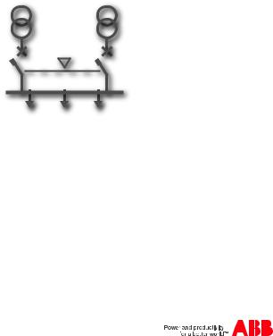
4.1 Switching Main Line – Emergency Line (2CBs)
Description
Both lines are normally present; in cause of anomaly on the main line, ATS022 switches to the emergency line used as the reserve line.
KA00428
Figure 4.1: 2CBs application layout – generator not in use
1SDH000760R0002 |
8 |
4. Applications of device ATS022 |
Installation and operating instructions, ATS022 |
|
|
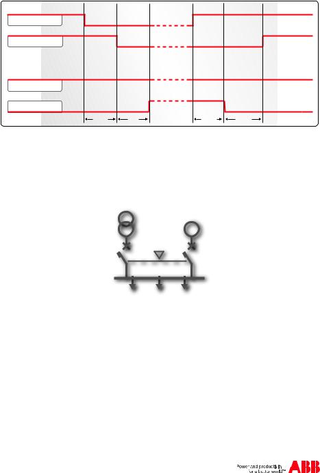
Time diagrams
Line 1 ok
CB1 CLOSED
Line 2 ok
CB2 CLOSED
TS |
TCE |
TBS |
TCN |
Figure 4.2: 2CBs application time diagram - main line LN1
4.2 Switching Main Line – Emergency generator (2CBs)
Description
In case of main line failure ATS022 automatically starts up an emergency generator and, as soon as power on the generator side is available, ATS022 starts the automatic switching procedure.
G
KA00427
Figure 4.3: 2CBs application layout – generator in use
1SDH000760R0002 |
9 |
Installation and operating instructions, ATS022 |
4. |
Applications of device ATS022 |
|
|
|
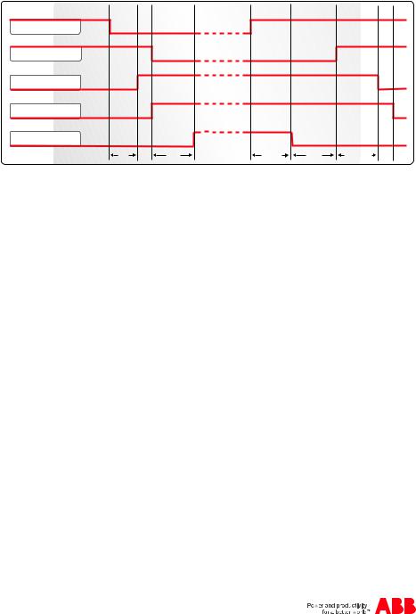
Time diagrams
Line 1 ok
CB1 CLOSED
Gen start
Line 2 ok
CB2 CLOSED
TS |
TCE |
TBS |
TCN |
TGOFF |
Figure 4.4: 2CBs application time diagram - generator in use
4.3 Non priority loads control (NPL)
Description
In case of main line failure the ATS022 starts the switching procedure and controls the non priority loads by opening closing circuit breaker CB3.
ATS022 acquires the CB3 open/close status from the dedicated input DI11 and commands the opening and closing by activating output DO11.
The application of non priority loads requires the use of two CT-AWE typed timed relays for operating the opening and closing of CB3.
Two configurations are possible for utilisation depending on the position of circuit breaker CB3:
•CB3 in Bus Tie position (3CBs NPL – BUS TIE)
•CB3 on starting line (3CBs NPL).
It is possible to select from two options from the menu on the display:
•only disconnection of non priority loads by opening CB3 (manual re-closure). In this case timed relays CT-AWE are not necessary
•disconnection and re-connection of non priority loads by opening and closing of CB3
For more details refer to the wiring diagrams of the product.
1SDH000760R0002 |
10 |
4. Applications of device ATS022 |
Installation and operating instructions, ATS022 |
|
|
CB1 |
CB2 |
CB3
NPL
Figure 4.5: Application layout 3CBs NPL BUSTIE
CB1 |
CB2 |
CB3
NPL
Figure 4.6: Application layout 3CBs NPL
1SDH000760R0002 |
11 |

Installation and operating instructions, ATS022 |
4. |
Applications of device ATS022 |
|
|
|
Time diagrams
Line 1 ok
CB1 CLOSED
Gen start
Line 2 ok
CB2 CLOSED
CB3 CLOSED
TS |
TCE |
TBS |
TCN |
TGOFF |
Figure 4.7: Application time diagram 3CBs NPL BUS TIE - generator in use
Line 1 ok
CB1 CLOSED
Line 2 ok
CB2 CLOSED
CB3 CLOSED
TS |
TCE |
TBS |
TCN |
Figure 4.8: Application time diagram 3CBs NPL BUS TIE - generator not in use - main line LN1
1SDH000760R0002 |
12 |

4. Applications of device ATS022 |
|
Installation and operating instructions, ATS022 |
||
Line 1 ok |
|
|
|
|
CB1 CLOSED |
|
|
|
|
Gen start |
|
|
|
|
Line 2 ok |
|
|
|
|
CB2 CLOSED |
|
|
|
|
CB3 CLOSED |
|
|
|
|
TS |
TCE |
TBS |
TCN |
TGOFF |
Figure 4.9: Application time diagram 3CBs NPLgenerator in use
Line 1 ok
CB1 CLOSED
Line 2 ok
CB2 CLOSED
CB3 CLOSED
TS |
TCE |
TBS |
TCN |
Figure 4.10: Application time diagram 3CBs NPL - generator not in use - main line LN1
1SDH000760R0002 |
13 |
 Loading...