


 Loading...
ABB industrial drives
Firmware manual
ACS880-M04 machinery control program
List of related manuals
Drive hardware manuals |
Code (English) |
ACS880-M04 drives hardware manual |
3AXD50000028613 |
*ACS880-01 drives hardware manual |
3AUA0000078093 |
*ACS880-04 drive modules (200 to 710 kW, 300 to 700 hp) 3AUA0000128301 hardware manual
Drive firmware manuals and guides |
|
Adaptive programming application guide |
3AXD50000028574 |
Drive (IEC 61131-3) application programming manual |
3AUA0000127808 |
Option manuals and guides |
|
ACS880-M04 Quick installation guide |
3AXD50000032345 |
ACX-AP-x Assistant control panels user’s manual |
3AUA0000085685 |
ACS-BP-S Basic control panels user’s manual |
3AXD50000032527 |
Drive composer Start-up and maintenance PC tool User’s |
3AUA0000094606 |
manual |
|
Manuals and quick guides for I/O extension modules, fieldbus adapters, encoder interfaces, etc.
You can find manuals and other product documents in PDF format on the Internet. See section Document library on the Internet on the inside of the back cover. For manuals not available in the Document library, contact your local ABB representative.
*A list of links to all manuals applicable to this product is available in the Document library:

Firmware manual
ACS880-M04 machinery control program
Table of contents
2016 ABB Oy. All Rights Reserved. |
3AXD50000030629 Rev A |
|
EN |
|
EFFECTIVE: 2016-04-11 |

Table of contents |
5 |
Table of contents |
|
List of related manuals . . . . . . . . . . . . . . . . . . . . . . . . . . . . . . . . . . . . . . . . . . . . . . . . . . . . . . |
. 2 |
1. Introduction to the manual |
|
What this chapter contains . . . . . . . . . . . . . . . . . . . . . . . . . . . . . . . . . . . . . . . . . . . . . . . . . . . |
11 |
Applicability . . . . . . . . . . . . . . . . . . . . . . . . . . . . . . . . . . . . . . . . . . . . . . . . . . . . . . . . . . . . . . . |
11 |
Safety instructions . . . . . . . . . . . . . . . . . . . . . . . . . . . . . . . . . . . . . . . . . . . . . . . . . . . . . . . . . . |
11 |
Target audience . . . . . . . . . . . . . . . . . . . . . . . . . . . . . . . . . . . . . . . . . . . . . . . . . . . . . . . . . . . . |
11 |
Contents of the manual . . . . . . . . . . . . . . . . . . . . . . . . . . . . . . . . . . . . . . . . . . . . . . . . . . . . . . |
12 |
Related documents . . . . . . . . . . . . . . . . . . . . . . . . . . . . . . . . . . . . . . . . . . . . . . . . . . . . . . . . . |
12 |
Terms and abbreviations . . . . . . . . . . . . . . . . . . . . . . . . . . . . . . . . . . . . . . . . . . . . . . . . . . . . . |
13 |
2. Using the control panel |
|
3. Start-up |
|
Contents of this chapter . . . . . . . . . . . . . . . . . . . . . . . . . . . . . . . . . . . . . . . . . . . . . . . . . . . . . . |
17 |
Before you start . . . . . . . . . . . . . . . . . . . . . . . . . . . . . . . . . . . . . . . . . . . . . . . . . . . . . . . . . . . . |
17 |
Safety . . . . . . . . . . . . . . . . . . . . . . . . . . . . . . . . . . . . . . . . . . . . . . . . . . . . . . . . . . . . . . . . . . . |
17 |
Start-up . . . . . . . . . . . . . . . . . . . . . . . . . . . . . . . . . . . . . . . . . . . . . . . . . . . . . . . . . . . . . . . . . . |
18 |
4. Control locations and operating modes |
|
What this chapter contains . . . . . . . . . . . . . . . . . . . . . . . . . . . . . . . . . . . . . . . . . . . . . . . . . . . |
25 |
Local control vs. external control . . . . . . . . . . . . . . . . . . . . . . . . . . . . . . . . . . . . . . . . . . . . . . . |
26 |
Local control . . . . . . . . . . . . . . . . . . . . . . . . . . . . . . . . . . . . . . . . . . . . . . . . . . . . . . . . . . . |
26 |
External control . . . . . . . . . . . . . . . . . . . . . . . . . . . . . . . . . . . . . . . . . . . . . . . . . . . . . . . . . |
27 |
Operating modes of the drive . . . . . . . . . . . . . . . . . . . . . . . . . . . . . . . . . . . . . . . . . . . . . . . . . |
28 |
Speed control mode . . . . . . . . . . . . . . . . . . . . . . . . . . . . . . . . . . . . . . . . . . . . . . . . . . . . . |
29 |
Torque control mode . . . . . . . . . . . . . . . . . . . . . . . . . . . . . . . . . . . . . . . . . . . . . . . . . . . . . |
29 |
Frequency control mode . . . . . . . . . . . . . . . . . . . . . . . . . . . . . . . . . . . . . . . . . . . . . . . . . . |
29 |
Special control modes . . . . . . . . . . . . . . . . . . . . . . . . . . . . . . . . . . . . . . . . . . . . . . . . . . . . |
29 |
5. Program features |
|
What this chapter contains . . . . . . . . . . . . . . . . . . . . . . . . . . . . . . . . . . . . . . . . . . . . . . . . . . . |
31 |
Drive configuration and programming . . . . . . . . . . . . . . . . . . . . . . . . . . . . . . . . . . . . . . . . . . . |
32 |
Programming via parameters . . . . . . . . . . . . . . . . . . . . . . . . . . . . . . . . . . . . . . . . . . . . . . |
32 |
Adaptive programming . . . . . . . . . . . . . . . . . . . . . . . . . . . . . . . . . . . . . . . . . . . . . . . . . . . |
33 |
Application programming . . . . . . . . . . . . . . . . . . . . . . . . . . . . . . . . . . . . . . . . . . . . . . . . . |
35 |
Control interfaces . . . . . . . . . . . . . . . . . . . . . . . . . . . . . . . . . . . . . . . . . . . . . . . . . . . . . . . . . . |
36 |
Programmable analog inputs . . . . . . . . . . . . . . . . . . . . . . . . . . . . . . . . . . . . . . . . . . . . . . |
36 |
Programmable analog outputs . . . . . . . . . . . . . . . . . . . . . . . . . . . . . . . . . . . . . . . . . . . . . |
36 |
Programmable digital inputs and outputs . . . . . . . . . . . . . . . . . . . . . . . . . . . . . . . . . . . . . |
36 |
Programmable relay outputs . . . . . . . . . . . . . . . . . . . . . . . . . . . . . . . . . . . . . . . . . . . . . . . |
37 |
Programmable I/O extensions . . . . . . . . . . . . . . . . . . . . . . . . . . . . . . . . . . . . . . . . . . . . . . |
37 |
Fieldbus control . . . . . . . . . . . . . . . . . . . . . . . . . . . . . . . . . . . . . . . . . . . . . . . . . . . . . . . . . |
38 |

6 Table of contents
Master/follower functionality . . . . . . . . . . . . . . . . . . . . . . . . . . . . . . . . . . . . . . . . . . . . . . . 39 External controller interface . . . . . . . . . . . . . . . . . . . . . . . . . . . . . . . . . . . . . . . . . . . . . . . 44 Motor control . . . . . . . . . . . . . . . . . . . . . . . . . . . . . . . . . . . . . . . . . . . . . . . . . . . . . . . . . . . . . 45 Direct torque control (DTC) . . . . . . . . . . . . . . . . . . . . . . . . . . . . . . . . . . . . . . . . . . . . . . . 45 Reference ramping . . . . . . . . . . . . . . . . . . . . . . . . . . . . . . . . . . . . . . . . . . . . . . . . . . . . . . 45 Constant speeds/frequencies . . . . . . . . . . . . . . . . . . . . . . . . . . . . . . . . . . . . . . . . . . . . . . 46 Critical speeds/frequencies . . . . . . . . . . . . . . . . . . . . . . . . . . . . . . . . . . . . . . . . . . . . . . . 46 Speed controller autotune . . . . . . . . . . . . . . . . . . . . . . . . . . . . . . . . . . . . . . . . . . . . . . . . 47 Oscillation damping . . . . . . . . . . . . . . . . . . . . . . . . . . . . . . . . . . . . . . . . . . . . . . . . . . . . . 50 Rush control . . . . . . . . . . . . . . . . . . . . . . . . . . . . . . . . . . . . . . . . . . . . . . . . . . . . . . . . . . . 51 Encoder support . . . . . . . . . . . . . . . . . . . . . . . . . . . . . . . . . . . . . . . . . . . . . . . . . . . . . . . . 52 Position counter . . . . . . . . . . . . . . . . . . . . . . . . . . . . . . . . . . . . . . . . . . . . . . . . . . . . . . . . 54 Jogging . . . . . . . . . . . . . . . . . . . . . . . . . . . . . . . . . . . . . . . . . . . . . . . . . . . . . . . . . . . . . . 57 Scalar motor control . . . . . . . . . . . . . . . . . . . . . . . . . . . . . . . . . . . . . . . . . . . . . . . . . . . . . 59 Autophasing . . . . . . . . . . . . . . . . . . . . . . . . . . . . . . . . . . . . . . . . . . . . . . . . . . . . . . . . . . . 60 Flux braking . . . . . . . . . . . . . . . . . . . . . . . . . . . . . . . . . . . . . . . . . . . . . . . . . . . . . . . . . . . 63 DC magnetization . . . . . . . . . . . . . . . . . . . . . . . . . . . . . . . . . . . . . . . . . . . . . . . . . . . . . . . 64 Application control . . . . . . . . . . . . . . . . . . . . . . . . . . . . . . . . . . . . . . . . . . . . . . . . . . . . . . . . . 67 Application macros . . . . . . . . . . . . . . . . . . . . . . . . . . . . . . . . . . . . . . . . . . . . . . . . . . . . . . 67 Motor potentiometer . . . . . . . . . . . . . . . . . . . . . . . . . . . . . . . . . . . . . . . . . . . . . . . . . . . . . 67 DC voltage control . . . . . . . . . . . . . . . . . . . . . . . . . . . . . . . . . . . . . . . . . . . . . . . . . . . . . . . . . 68 Overvoltage control . . . . . . . . . . . . . . . . . . . . . . . . . . . . . . . . . . . . . . . . . . . . . . . . . . . . . 68 Undervoltage control (power loss ride-through) . . . . . . . . . . . . . . . . . . . . . . . . . . . . . . . . 68 Voltage control and trip limits . . . . . . . . . . . . . . . . . . . . . . . . . . . . . . . . . . . . . . . . . . . . . . 70 Brake chopper . . . . . . . . . . . . . . . . . . . . . . . . . . . . . . . . . . . . . . . . . . . . . . . . . . . . . . . . . 70 Safety and protections . . . . . . . . . . . . . . . . . . . . . . . . . . . . . . . . . . . . . . . . . . . . . . . . . . . . . . 72 Emergency stop . . . . . . . . . . . . . . . . . . . . . . . . . . . . . . . . . . . . . . . . . . . . . . . . . . . . . . . . 72 Motor thermal protection . . . . . . . . . . . . . . . . . . . . . . . . . . . . . . . . . . . . . . . . . . . . . . . . . 73 Thermal protection of motor cable . . . . . . . . . . . . . . . . . . . . . . . . . . . . . . . . . . . . . . . . . . 76 Other programmable protection functions . . . . . . . . . . . . . . . . . . . . . . . . . . . . . . . . . . . . 76 Automatic fault resets . . . . . . . . . . . . . . . . . . . . . . . . . . . . . . . . . . . . . . . . . . . . . . . . . . . . 78 Diagnostics . . . . . . . . . . . . . . . . . . . . . . . . . . . . . . . . . . . . . . . . . . . . . . . . . . . . . . . . . . . . . . . 79 Fault and warning messages, data logging . . . . . . . . . . . . . . . . . . . . . . . . . . . . . . . . . . . 79 Signal supervision . . . . . . . . . . . . . . . . . . . . . . . . . . . . . . . . . . . . . . . . . . . . . . . . . . . . . . 79 Maintenance timers and counters . . . . . . . . . . . . . . . . . . . . . . . . . . . . . . . . . . . . . . . . . . 79 Energy saving calculators . . . . . . . . . . . . . . . . . . . . . . . . . . . . . . . . . . . . . . . . . . . . . . . . 80 Load analyzer . . . . . . . . . . . . . . . . . . . . . . . . . . . . . . . . . . . . . . . . . . . . . . . . . . . . . . . . . . 80 Miscellaneous . . . . . . . . . . . . . . . . . . . . . . . . . . . . . . . . . . . . . . . . . . . . . . . . . . . . . . . . . . . . . 82 User parameter sets . . . . . . . . . . . . . . . . . . . . . . . . . . . . . . . . . . . . . . . . . . . . . . . . . . . . . 82 Data storage parameters . . . . . . . . . . . . . . . . . . . . . . . . . . . . . . . . . . . . . . . . . . . . . . . . . 82 du/dt filter support . . . . . . . . . . . . . . . . . . . . . . . . . . . . . . . . . . . . . . . . . . . . . . . . . . . . . . 83
6. Application macros
What this chapter contains . . . . . . . . . . . . . . . . . . . . . . . . . . . . . . . . . . . . . . . . . . . . . . . . . . . 85 General . . . . . . . . . . . . . . . . . . . . . . . . . . . . . . . . . . . . . . . . . . . . . . . . . . . . . . . . . . . . . . . . . . 85 Factory macro . . . . . . . . . . . . . . . . . . . . . . . . . . . . . . . . . . . . . . . . . . . . . . . . . . . . . . . . . . . . 86 Default parameter settings for the Factory macro . . . . . . . . . . . . . . . . . . . . . . . . . . . . . . 86 Default control connections for the Factory macro . . . . . . . . . . . . . . . . . . . . . . . . . . . . . . 87

|
|
Table of contents 7 |
7. Parameters |
|
|
What this chapter contains . . . . . . . . . . . . . . . . . . . . . . . . . . . . . . . . . . . |
. . . . . . . . . . . . . . . . 89 |
|
Terms and abbreviations . . . . . . . . . . . . . . . . . . . . . . . . . . . . . . . . . . . . . |
. . . . . . . . . . . . . . . . 90 |
|
Summary of parameter groups . . . . . . . . . . . . . . . . . . . . . . . . . . . . . . . . |
. . . . . . . . . . . . . . . . 91 |
|
Parameter listing . . . . . . . . . . . . . . . . . . . . . . . . . . . . . . . . . . . . . . . . . . . . |
. . . . . . . . . . . . . . . 94 |
|
01 |
Actual values . . . . . . . . . . . . . . . . . . . . . . . . . . . . . . . . . . . . . . . . . |
. . . . . . . . . . . . . . . 94 |
03 |
Input references . . . . . . . . . . . . . . . . . . . . . . . . . . . . . . . . . . . . . . . |
. . . . . . . . . . . . . . . 98 |
04 |
Warnings and faults . . . . . . . . . . . . . . . . . . . . . . . . . . . . . . . . . . . . |
. . . . . . . . . . . . . . . 99 |
05 |
Diagnostics . . . . . . . . . . . . . . . . . . . . . . . . . . . . . . . . . . . . . . . . . . . |
. . . . . . . . . . . . . . 106 |
06 |
Control and status words . . . . . . . . . . . . . . . . . . . . . . . . . . . . . . . . |
. . . . . . . . . . . . . . 108 |
07 |
System info . . . . . . . . . . . . . . . . . . . . . . . . . . . . . . . . . . . . . . . . . . |
. . . . . . . . . . . . . . 120 |
10 |
Standard DI, RO . . . . . . . . . . . . . . . . . . . . . . . . . . . . . . . . . . . . . . . |
. . . . . . . . . . . . . . 122 |
11 |
Standard DIO, FI, FO . . . . . . . . . . . . . . . . . . . . . . . . . . . . . . . . . . . |
. . . . . . . . . . . . . . 130 |
12 |
Standard AI . . . . . . . . . . . . . . . . . . . . . . . . . . . . . . . . . . . . . . . . . . |
. . . . . . . . . . . . . . 136 |
13 Standard AO . . . . . . . . . . . . . . . . . . . . . . . . . . . . . . . . . . . . . . . . . |
. . . . . . . . . . . . . . 141 |
|
14 |
I/O extension module 1 . . . . . . . . . . . . . . . . . . . . . . . . . . . . . . . . . |
. . . . . . . . . . . . . . 147 |
15 |
I/O extension module 2 . . . . . . . . . . . . . . . . . . . . . . . . . . . . . . . . . |
. . . . . . . . . . . . . . 169 |
19 |
Operation mode . . . . . . . . . . . . . . . . . . . . . . . . . . . . . . . . . . . . . . . |
. . . . . . . . . . . . . . 173 |
20 |
Start/stop/direction . . . . . . . . . . . . . . . . . . . . . . . . . . . . . . . . . . . . . |
. . . . . . . . . . . . . . 176 |
21 |
Start/stop mode . . . . . . . . . . . . . . . . . . . . . . . . . . . . . . . . . . . . . . . |
. . . . . . . . . . . . . . 188 |
22 |
Speed reference selection . . . . . . . . . . . . . . . . . . . . . . . . . . . . . . . |
. . . . . . . . . . . . . . 198 |
23 |
Speed reference ramp . . . . . . . . . . . . . . . . . . . . . . . . . . . . . . . . . . |
. . . . . . . . . . . . . . 209 |
24 |
Speed reference conditioning . . . . . . . . . . . . . . . . . . . . . . . . . . . . |
. . . . . . . . . . . . . . 217 |
25 |
Speed control . . . . . . . . . . . . . . . . . . . . . . . . . . . . . . . . . . . . . . . . . |
. . . . . . . . . . . . . . 220 |
26 |
Torque reference chain . . . . . . . . . . . . . . . . . . . . . . . . . . . . . . . . . |
. . . . . . . . . . . . . . 234 |
28 |
Frequency reference chain . . . . . . . . . . . . . . . . . . . . . . . . . . . . . . |
. . . . . . . . . . . . . . 243 |
30 |
Limits . . . . . . . . . . . . . . . . . . . . . . . . . . . . . . . . . . . . . . . . . . . . . . . |
. . . . . . . . . . . . . . 255 |
31 |
Fault functions . . . . . . . . . . . . . . . . . . . . . . . . . . . . . . . . . . . . . . . . |
. . . . . . . . . . . . . . 263 |
32 |
Supervision . . . . . . . . . . . . . . . . . . . . . . . . . . . . . . . . . . . . . . . . . . |
. . . . . . . . . . . . . . 276 |
33 |
Generic timer & counter . . . . . . . . . . . . . . . . . . . . . . . . . . . . . . . . . |
. . . . . . . . . . . . . . 280 |
35 |
Motor thermal protection . . . . . . . . . . . . . . . . . . . . . . . . . . . . . . . . |
. . . . . . . . . . . . . . 290 |
36 |
Load analyzer . . . . . . . . . . . . . . . . . . . . . . . . . . . . . . . . . . . . . . . . . |
. . . . . . . . . . . . . . 304 |
43 |
Brake chopper . . . . . . . . . . . . . . . . . . . . . . . . . . . . . . . . . . . . . . . . |
. . . . . . . . . . . . . . 308 |
44 |
Mechanical brake control . . . . . . . . . . . . . . . . . . . . . . . . . . . . . . . . |
. . . . . . . . . . . . . . 310 |
45 |
Energy efficiency . . . . . . . . . . . . . . . . . . . . . . . . . . . . . . . . . . . . . . |
. . . . . . . . . . . . . . 316 |
46 |
Monitoring/scaling settings . . . . . . . . . . . . . . . . . . . . . . . . . . . . . . . |
. . . . . . . . . . . . . . 320 |
47 |
Data storage . . . . . . . . . . . . . . . . . . . . . . . . . . . . . . . . . . . . . . . . . . |
. . . . . . . . . . . . . . 324 |
49 |
Panel port communication . . . . . . . . . . . . . . . . . . . . . . . . . . . . . . . |
. . . . . . . . . . . . . . 327 |
50 |
Fieldbus adapter (FBA) . . . . . . . . . . . . . . . . . . . . . . . . . . . . . . . . . |
. . . . . . . . . . . . . . 330 |
51 |
FBA A settings . . . . . . . . . . . . . . . . . . . . . . . . . . . . . . . . . . . . . . . . |
. . . . . . . . . . . . . . 341 |
52 |
FBA A data in . . . . . . . . . . . . . . . . . . . . . . . . . . . . . . . . . . . . . . . . . |
. . . . . . . . . . . . . . 342 |
53 |
FBA A data out . . . . . . . . . . . . . . . . . . . . . . . . . . . . . . . . . . . . . . . . |
. . . . . . . . . . . . . . 343 |
54 |
FBA B settings . . . . . . . . . . . . . . . . . . . . . . . . . . . . . . . . . . . . . . . . |
. . . . . . . . . . . . . . 344 |
55 |
FBA B data in . . . . . . . . . . . . . . . . . . . . . . . . . . . . . . . . . . . . . . . . . |
. . . . . . . . . . . . . . 345 |
56 |
FBA B data out . . . . . . . . . . . . . . . . . . . . . . . . . . . . . . . . . . . . . . . . |
. . . . . . . . . . . . . . 346 |
58 |
Embedded fieldbus . . . . . . . . . . . . . . . . . . . . . . . . . . . . . . . . . . . . |
. . . . . . . . . . . . . . 346 |
60 DDCS communication . . . . . . . . . . . . . . . . . . . . . . . . . . . . . . . . . . |
. . . . . . . . . . . . . . 357 |
|
61 |
D2D and DDCS transmit data . . . . . . . . . . . . . . . . . . . . . . . . . . . . |
. . . . . . . . . . . . . . 366 |
62 D2D and DDCS receive data . . . . . . . . . . . . . . . . . . . . . . . . . . . . . |
. . . . . . . . . . . . . . 370 |
|
90 |
Feedback selection . . . . . . . . . . . . . . . . . . . . . . . . . . . . . . . . . . . . |
. . . . . . . . . . . . . . 379 |

8 Table of contents
91 Encoder module settings . . . . . . . . . . . . . . . . . . . . . . . . . . . . . . . . . . . . . . . . . . . . . . 391 92 Encoder 1 configuration . . . . . . . . . . . . . . . . . . . . . . . . . . . . . . . . . . . . . . . . . . . . . . 395 93 Encoder 2 configuration . . . . . . . . . . . . . . . . . . . . . . . . . . . . . . . . . . . . . . . . . . . . . . 403 95 HW configuration . . . . . . . . . . . . . . . . . . . . . . . . . . . . . . . . . . . . . . . . . . . . . . . . . . . . 406 96 System . . . . . . . . . . . . . . . . . . . . . . . . . . . . . . . . . . . . . . . . . . . . . . . . . . . . . . . . . . . 410 97 Motor control . . . . . . . . . . . . . . . . . . . . . . . . . . . . . . . . . . . . . . . . . . . . . . . . . . . . . . . 419 98 User motor parameters . . . . . . . . . . . . . . . . . . . . . . . . . . . . . . . . . . . . . . . . . . . . . . . 423 99 Motor data . . . . . . . . . . . . . . . . . . . . . . . . . . . . . . . . . . . . . . . . . . . . . . . . . . . . . . . . . 425 200 Safety . . . . . . . . . . . . . . . . . . . . . . . . . . . . . . . . . . . . . . . . . . . . . . . . . . . . . . . . . . . 433
8. Additional parameter data
What this chapter contains . . . . . . . . . . . . . . . . . . . . . . . . . . . . . . . . . . . . . . . . . . . . . . . . . . 435 Terms and abbreviations . . . . . . . . . . . . . . . . . . . . . . . . . . . . . . . . . . . . . . . . . . . . . . . . . . . 435 Fieldbus addresses . . . . . . . . . . . . . . . . . . . . . . . . . . . . . . . . . . . . . . . . . . . . . . . . . . . . . . . 436 Parameter groups 1…9 . . . . . . . . . . . . . . . . . . . . . . . . . . . . . . . . . . . . . . . . . . . . . . . . . . . . 437 Parameter groups 10…99 . . . . . . . . . . . . . . . . . . . . . . . . . . . . . . . . . . . . . . . . . . . . . . . . . . 442
9. Fault tracing
What this chapter contains . . . . . . . . . . . . . . . . . . . . . . . . . . . . . . . . . . . . . . . . . . . . . . . . . . 479 Safety . . . . . . . . . . . . . . . . . . . . . . . . . . . . . . . . . . . . . . . . . . . . . . . . . . . . . . . . . . . . . . . . . . 479 Indications . . . . . . . . . . . . . . . . . . . . . . . . . . . . . . . . . . . . . . . . . . . . . . . . . . . . . . . . . . . . . . 479 Warnings and faults . . . . . . . . . . . . . . . . . . . . . . . . . . . . . . . . . . . . . . . . . . . . . . . . . . . . 479 Pure events . . . . . . . . . . . . . . . . . . . . . . . . . . . . . . . . . . . . . . . . . . . . . . . . . . . . . . . . . . 480 Editable messages . . . . . . . . . . . . . . . . . . . . . . . . . . . . . . . . . . . . . . . . . . . . . . . . . . . . . 480 Warning/fault history and analysis . . . . . . . . . . . . . . . . . . . . . . . . . . . . . . . . . . . . . . . . . . . . 480 Event logs . . . . . . . . . . . . . . . . . . . . . . . . . . . . . . . . . . . . . . . . . . . . . . . . . . . . . . . . . . . 480 Other data loggers . . . . . . . . . . . . . . . . . . . . . . . . . . . . . . . . . . . . . . . . . . . . . . . . . . . . . 481 Parameters that contain warning/fault information . . . . . . . . . . . . . . . . . . . . . . . . . . . . . 481 QR Code generation for mobile service application . . . . . . . . . . . . . . . . . . . . . . . . . . . . . . . 482 Warning messages . . . . . . . . . . . . . . . . . . . . . . . . . . . . . . . . . . . . . . . . . . . . . . . . . . . . . . . . 483 Fault messages . . . . . . . . . . . . . . . . . . . . . . . . . . . . . . . . . . . . . . . . . . . . . . . . . . . . . . . . . . 503
10. Fieldbus control through the embedded fieldbus interface (EFB)
What this chapter contains . . . . . . . . . . . . . . . . . . . . . . . . . . . . . . . . . . . . . . . . . . . . . . . . . . 527 System overview . . . . . . . . . . . . . . . . . . . . . . . . . . . . . . . . . . . . . . . . . . . . . . . . . . . . . . . . . 527 Connecting the fieldbus to the drive . . . . . . . . . . . . . . . . . . . . . . . . . . . . . . . . . . . . . . . . . . . 528 Setting up the embedded fieldbus interface . . . . . . . . . . . . . . . . . . . . . . . . . . . . . . . . . . . . . 529 Setting the drive control parameters . . . . . . . . . . . . . . . . . . . . . . . . . . . . . . . . . . . . . . . . . . 530 Basics of the embedded fieldbus interface . . . . . . . . . . . . . . . . . . . . . . . . . . . . . . . . . . . . . . 533
Control word and Status word . . . . . . . . . . . . . . . . . . . . . . . . . . . . . . . . . . . . . . . . . . . . 534 References . . . . . . . . . . . . . . . . . . . . . . . . . . . . . . . . . . . . . . . . . . . . . . . . . . . . . . . . . . . 534 Actual values . . . . . . . . . . . . . . . . . . . . . . . . . . . . . . . . . . . . . . . . . . . . . . . . . . . . . . . . . 534 Data input/outputs . . . . . . . . . . . . . . . . . . . . . . . . . . . . . . . . . . . . . . . . . . . . . . . . . . . . . 534 Register addressing . . . . . . . . . . . . . . . . . . . . . . . . . . . . . . . . . . . . . . . . . . . . . . . . . . . . 535
About the control profiles . . . . . . . . . . . . . . . . . . . . . . . . . . . . . . . . . . . . . . . . . . . . . . . . . . . 536 The ABB Drives profile . . . . . . . . . . . . . . . . . . . . . . . . . . . . . . . . . . . . . . . . . . . . . . . . . . . . . 537 Control Word . . . . . . . . . . . . . . . . . . . . . . . . . . . . . . . . . . . . . . . . . . . . . . . . . . . . . . . . . 537 Status Word . . . . . . . . . . . . . . . . . . . . . . . . . . . . . . . . . . . . . . . . . . . . . . . . . . . . . . . . . . 539

Table of contents 9
State transition diagram . . . . . . . . . . . . . . . . . . . . . . . . . . . . . . . . . . . . . . . . . . . . . . . . . 540 References . . . . . . . . . . . . . . . . . . . . . . . . . . . . . . . . . . . . . . . . . . . . . . . . . . . . . . . . . . . 541 Actual values . . . . . . . . . . . . . . . . . . . . . . . . . . . . . . . . . . . . . . . . . . . . . . . . . . . . . . . . . . 542 Modbus holding register addresses . . . . . . . . . . . . . . . . . . . . . . . . . . . . . . . . . . . . . . . . 543 The Transparent profile . . . . . . . . . . . . . . . . . . . . . . . . . . . . . . . . . . . . . . . . . . . . . . . . . . . . . 544 Modbus function codes . . . . . . . . . . . . . . . . . . . . . . . . . . . . . . . . . . . . . . . . . . . . . . . . . . . . . 545 Exception codes . . . . . . . . . . . . . . . . . . . . . . . . . . . . . . . . . . . . . . . . . . . . . . . . . . . . . . . . . . 546 Coils (0xxxx reference set) . . . . . . . . . . . . . . . . . . . . . . . . . . . . . . . . . . . . . . . . . . . . . . . . . . 547 Discrete inputs (1xxxx reference set) . . . . . . . . . . . . . . . . . . . . . . . . . . . . . . . . . . . . . . . . . . 548 Error code registers (holding registers 400090…400100) . . . . . . . . . . . . . . . . . . . . . . . . . . . 550
11. Fieldbus control through a fieldbus adapter |
|
What this chapter contains . . . . . . . . . . . . . . . . . . . . . . . . . . . . . . . . . . . . . . . . . . . . . . . . . . |
551 |
System overview . . . . . . . . . . . . . . . . . . . . . . . . . . . . . . . . . . . . . . . . . . . . . . . . . . . . . . . . . . |
551 |
Basics of the fieldbus control interface . . . . . . . . . . . . . . . . . . . . . . . . . . . . . . . . . . . . . . . . . |
554 |
Control word and Status word . . . . . . . . . . . . . . . . . . . . . . . . . . . . . . . . . . . . . . . . . . . . . |
555 |
References . . . . . . . . . . . . . . . . . . . . . . . . . . . . . . . . . . . . . . . . . . . . . . . . . . . . . . . . . . . |
556 |
Actual values . . . . . . . . . . . . . . . . . . . . . . . . . . . . . . . . . . . . . . . . . . . . . . . . . . . . . . . . . . |
557 |
Contents of the fieldbus Control word . . . . . . . . . . . . . . . . . . . . . . . . . . . . . . . . . . . . . . . |
558 |
Contents of the fieldbus Status word . . . . . . . . . . . . . . . . . . . . . . . . . . . . . . . . . . . . . . . |
559 |
The state diagram . . . . . . . . . . . . . . . . . . . . . . . . . . . . . . . . . . . . . . . . . . . . . . . . . . . . . . |
560 |
Setting up the drive for fieldbus control . . . . . . . . . . . . . . . . . . . . . . . . . . . . . . . . . . . . . . . . . |
561 |
Parameter setting example: FPBA (PROFIBUS DP) . . . . . . . . . . . . . . . . . . . . . . . . . . . |
562 |
12. Control chain diagrams |
|
What this chapter contains . . . . . . . . . . . . . . . . . . . . . . . . . . . . . . . . . . . . . . . . . . . . . . . . . . |
565 |
Speed reference source selection I . . . . . . . . . . . . . . . . . . . . . . . . . . . . . . . . . . . . . . . . . . . . |
566 |
Speed reference source selection II . . . . . . . . . . . . . . . . . . . . . . . . . . . . . . . . . . . . . . . . . . . |
567 |
Speed reference ramping and shaping . . . . . . . . . . . . . . . . . . . . . . . . . . . . . . . . . . . . . . . . . |
568 |
Motor feedback configuration . . . . . . . . . . . . . . . . . . . . . . . . . . . . . . . . . . . . . . . . . . . . . . . . |
569 |
Load feedback and position counter configuration . . . . . . . . . . . . . . . . . . . . . . . . . . . . . . . . |
570 |
Speed error calculation . . . . . . . . . . . . . . . . . . . . . . . . . . . . . . . . . . . . . . . . . . . . . . . . . . . . . |
571 |
Speed controller . . . . . . . . . . . . . . . . . . . . . . . . . . . . . . . . . . . . . . . . . . . . . . . . . . . . . . . . . . |
572 |
Torque reference source selection and modification . . . . . . . . . . . . . . . . . . . . . . . . . . . . . . . |
573 |
Operating mode selection . . . . . . . . . . . . . . . . . . . . . . . . . . . . . . . . . . . . . . . . . . . . . . . . . . . |
574 |
Reference selection for torque controller . . . . . . . . . . . . . . . . . . . . . . . . . . . . . . . . . . . . . . . . |
575 |
Torque limitation . . . . . . . . . . . . . . . . . . . . . . . . . . . . . . . . . . . . . . . . . . . . . . . . . . . . . . . . . . |
576 |
Torque controller . . . . . . . . . . . . . . . . . . . . . . . . . . . . . . . . . . . . . . . . . . . . . . . . . . . . . . . . . . |
577 |
Frequency reference selection . . . . . . . . . . . . . . . . . . . . . . . . . . . . . . . . . . . . . . . . . . . . . . . |
578 |
Frequency reference modification . . . . . . . . . . . . . . . . . . . . . . . . . . . . . . . . . . . . . . . . . . . . . |
579 |
Master/Follower communication I (Master) . . . . . . . . . . . . . . . . . . . . . . . . . . . . . . . . . . . . . . |
580 |
Master/Follower communication II (Follower) . . . . . . . . . . . . . . . . . . . . . . . . . . . . . . . . . . . . |
581 |
Further information |
|
Product and service inquiries . . . . . . . . . . . . . . . . . . . . . . . . . . . . . . . . . . . . . . . . . . . . . . . . |
583 |
Product training . . . . . . . . . . . . . . . . . . . . . . . . . . . . . . . . . . . . . . . . . . . . . . . . . . . . . . . . . . . |
583 |
Providing feedback on ABB Drives manuals . . . . . . . . . . . . . . . . . . . . . . . . . . . . . . . . . . . . . |
583 |
Document library on the Internet . . . . . . . . . . . . . . . . . . . . . . . . . . . . . . . . . . . . . . . . . . . . . . |
583 |

10 Table of contents
Introduction to the manual 11
1
Introduction to the manual
What this chapter contains
This chapter describes the contents of the manual. It also contains information on the compatibility, safety and intended audience.
Applicability
This manual applies to ACS880-M04 machinery control program version 2.4x.
The firmware version of the control program is visible in parameter 07.05 Firmware version, or the System info in the main menu on the drive control panel.
Safety instructions
Obey all safety instructions delivered with the drive.
•Read the complete safety instructions before you install, commission, or use the drive. The complete safety instructions are delivered with the drive as part of the Hardware manual as a separate document.
•Read the firmware function-specific warnings and notes before changing parameter values. These warnings and notes are included in the parameter descriptions presented in chapter Parameters.
Target audience
This manual is intended for people who design, commission, or operate the drive system.

12 Introduction to the manual
Contents of the manual
This manual contains the following chapters:
•Using the control panel provides basic instructions for the use of the control panel.
•Control locations and operating modes describes the control locations and operating modes of the drive.
•Program features contains descriptions of the features of the ACS880-M04 primary control program.
•Application macros contains a short description of each macro together with a connection diagram. Macros are pre-defined applications which will save the user time when configuring the drive.
•Parameters describes the parameters used to program the drive.
•Additional parameter data contains further information on the parameters.
•Fault tracing lists the warning and fault messages with possible causes and remedies.
•Fieldbus control through the embedded fieldbus interface (EFB) describes the communication to and from a fieldbus network using the embedded fieldbus interface of the drive.
•Fieldbus control through a fieldbus adapter describes the communication to and from a fieldbus network using an optional fieldbus adapter module.
•Control chain diagrams showing the parameter structure within the drive.
Related documents
Note: A quick start-up sequence for a speed control application is provided by
ACS880-M04 Quick installation and start-up guide (3AXD50000032345), delivered with the drive.
See the List of related manuals on the inside of front cover.
|
Introduction to the manual 13 |
Terms and abbreviations |
|
|
|
Term/ |
Definition |
abbreviation |
|
|
|
ACS800 |
A product family of ABB drives |
|
|
ACS-AP-I, |
Assistant control panel. Type of control panels used with ACS880-M04 drives |
ACS-AP-W |
|
|
|
ACS-BP-S |
Basic control panel |
|
|
AI |
Analog input; interface for analog input signals |
|
|
AO |
Analog output; interface for analog output signals |
|
|
DC link |
DC circuit between rectifier and inverter |
|
|
DDCS |
Distributed drives communication system; a protocol used in communication |
|
between ABB drive equipment |
|
|
DI |
Digital input; interface for digital input signals |
|
|
DIO |
Digital input/output; interface that can be used as a digital input or output |
|
|
DO |
Digital output; interface for digital output signals |
|
|
Drive |
Frequency converter for controlling AC motors. The drive consists of a rectifier |
|
and an inverter connected together by the DC link. In drives up to |
|
approximately 500 kW, these are integrated into a single module (drive |
|
module). Larger drives typically consist of separate supply and inverter units. |
|
The ACS880-M04 primary control program is used to control the inverter part |
|
of the drive. |
|
|
DriveBus |
A communication link used by, for example, ABB controllers. ACS880-M04 |
|
drives can be connected to the DriveBus link of the controller. |
|
|
DTC |
Direct torque control. See page 45. |
|
|
FBA |
Fieldbus adapter |
|
|
FCAN-01 |
Optional CANopen adapter |
|
|
FCNA-01 |
Optional ControlNet adapter |
|
|
FDCO-0x |
Optional DDCS communication module |
|
|
FDNA-01 |
Optional DeviceNet adapter |
|
|
FECA-01 |
Optional EtherCAT® adapter |
|
|
FEN-01 |
Optional TTL encoder interface module |
|
|
FEN-11 |
Optional absolute encoder interface module |
|
|
FEN-21 |
Optional resolver interface module |
|
|
FEN-31 |
Optional HTL encoder interface module |
|
|
FENA-11 |
Optional Ethernet/IP, Modbus/TCP and PROFINET IO adapter |
|
|
FENA-21 |
Optional dual-port Ethernet/IP, Modbus/TCP and PROFINET IO adapter |
|
|
FEPL-02 |
Optional POWERLINK adapter |
|
|
FIO-01 |
Optional digital I/O extension module |
|
|
FIO-11 |
Optional analog I/O extension module |
|
|
FPBA-01 |
Optional PROFIBUS DP adapter |
|
|
FSCA-01 |
Optional Modbus/RTU adapter |
|
|
|
|
14 Introduction to the manual
Term/ |
Definition |
abbreviation |
|
|
|
FSO-xx |
Optional safety functions module |
|
|
HTL |
High-threshold logic |
|
|
ID run |
Motor identification run. During the identification run, the drive will identify the |
|
characteristics of the motor for optimum motor control. |
|
|
IGBT |
Insulated gate bipolar transistor; a voltage-controlled semiconductor type |
|
widely used in inverters and IGBT supply units due to their easy controllability |
|
and high switching frequency |
|
|
Inverter unit |
In large drives (> 500 kW approx.), the part of the drive that converts DC to |
|
AC for the motor. Consists of one or more inverter modules and their auxiliary |
|
components. |
|
|
I/O |
Input/Output |
|
|
ModuleBus |
A communication link used by, for example, ABB controllers. ACS880-M04 |
|
drives can be connected to the optical ModuleBus link of the controller. |
|
|
Motor-side |
See inverter unit. |
converter |
|
|
|
Network |
With fieldbus protocols based on the Common Industrial Protocol (CIPTM), |
control |
such as DeviceNet and Ethernet/IP, denotes the control of the drive using the |
|
Net Ctrl and Net Ref objects of the ODVA AC/DC Drive Profile. For more |
|
information, see www.odva.org, and the following manuals: |
|
• FDNA-01 DeviceNet adapter module User’s manual (3AFE68573360 |
|
[English]), and |
|
• FENA-01/-11 Ethernet adapter module User’s manual (3AUA0000093568 |
|
[English]). |
|
|
Parameter |
User-adjustable operation instruction to the drive, or signal measured or |
|
calculated by the drive |
|
|
PLC |
Programmable logic controller |
|
|
Power unit |
Contains the power electronics and power connections of the drive (or inverter |
|
module). The drive control unit is connected to the power unit. |
|
|
PTC |
Positive temperature coefficient |
|
|
RFG |
Ramp function generator. |
|
|
RO |
Relay output; interface for a digital output signal. Implemented with a relay. |
|
|
SSI |
Synchronous serial interface |
|
|
STO |
Safe torque off |
|
|
TTL |
Transistor-transistor logic |
|
|
UPS |
Uninterruptible power supply; power supply equipment with battery to |
|
maintain output voltage during power failure |
|
|
ZCU |
Type of control unit used in ACS880-M04 drives (primarily in drive modules, or |
|
inverter/supply units consisting of a single power module). Consists of an I/O |
|
board built into a plastic housing. |
|
Depending on the type of hardware, the control unit may be integrated into or |
|
fitted onto the drive/inverter module, or installed separately. |
|
|
|
|

Using the control panel 15
2
Using the control panel
Refer to
•ACX-AP-x assistant control panels user’s manual (3AUA0000085685 [English]) and
•ACS-BP-S assistant control panels user’s manual (3AXD50000032527 [English]).

16 Using the control panel

Start-up 17
3
Start-up
Contents of this chapter
This chapter describes the basic start-up sequence of an ACS880-M04 machinery drive.
In this guide, the drive is set up using the ACS-AP-I control panel. The start-up sequence can also be carried out using the Drive composer PC tool.
Before you start
Make sure the drive is mechanically and electrically installed as described in the
Quick installation guide and/or Hardware manual.
Safety
WARNING! Follow all safety instructions of the drive. Only qualified electricians are allowed to start up the drive. Never work on the drive, the brake chopper circuit, the motor cable or the motor when power is applied to the drive. Always make sure by measuring that no voltage is actually present.
WARNING! Make sure that the machinery into which the drive with brake control function is integrated fulfills the personnel safety regulations.
Note that the frequency converter (a Complete Drive Module or a Basic Drive Module, as defined in IEC 61800-2), is not considered as a safety device mentioned in the European Machinery Directive and related harmonized standards. Thus, the personnel safety of the complete machinery must not be based on a specific frequency converter feature (such as the brake control function), but it has to be implemented as defined in the application specific regulations.
18 Start-up
Start-up
Safety
WARNING! Obey all safety instructions for the drive. Only qualified electricians are allowed to start up the drive.
Check the installation. See the installation checklist in the Hardware manual.
Check that the starting of the motor does not cause any danger.
De-couple the driven machine if
•there is a risk of damage in case of an incorrect direction of rotation, or
•a Normal ID run is required during the drive start-up, when the load torque is higher than 20% or the machinery is not able to withstand the nominal torque transient during the ID run.
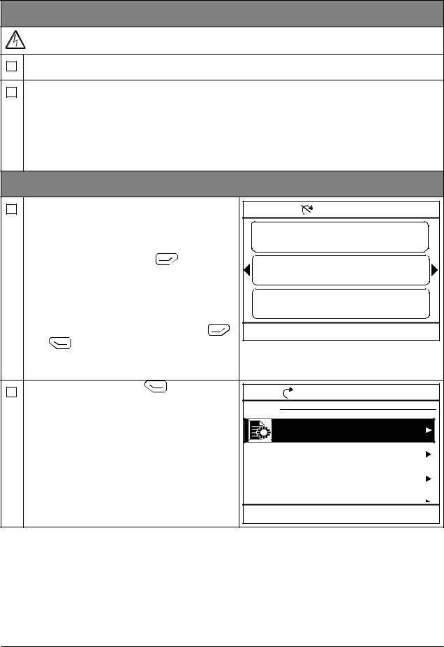
1 – Power-up, date and time settings
Power up the drive. |
|
Remote |
ACS880 |
0.0 rpm |
||
Note: It is normal that warning messages |
Motor speed used |
0.00 |
||||
appear at various points along the start-up |
||||||
process. To hide a message and to resume |
rpm |
|
|
|||
the start-up process, press |
. |
Motor current |
0.00 |
|||
Hide any warnings now to enter the Home |
A |
|
|
|||
view (shown on the right). |
|
% |
|
|
0.0 |
|
The two commands at the bottom of the |
Motor torque |
|
||||
|
|
|
|
|||
display (in this case, Options and Menu), |
Options |
12:34 |
Menu |
|||
show the functions of the two softkeys |
||||||
and |
located below the display. The |
|
|
|
|
|
commands assigned to the softkeys vary |
|
|
|
|
||
depending on the context. |
|
|
|
|
|
|
In the Home view, press |
(Menu). |
Remote |
|
0.0 rpm |
||
The main Menu (right) appears. |
Menu |
|
|
|
||
|
|
|
|
Parameters |
|
|
|
|
|
|
Assistants |
|
|
|
|
|
|
Energy efficiency |
|
|
|
|
|
Exit |
Event log 12:34 |
Select |
|
|
|
|
|
|
|
|
|
|
Start-up 19 |
||
|
|
|
|
|
|
|
|
|
|
||
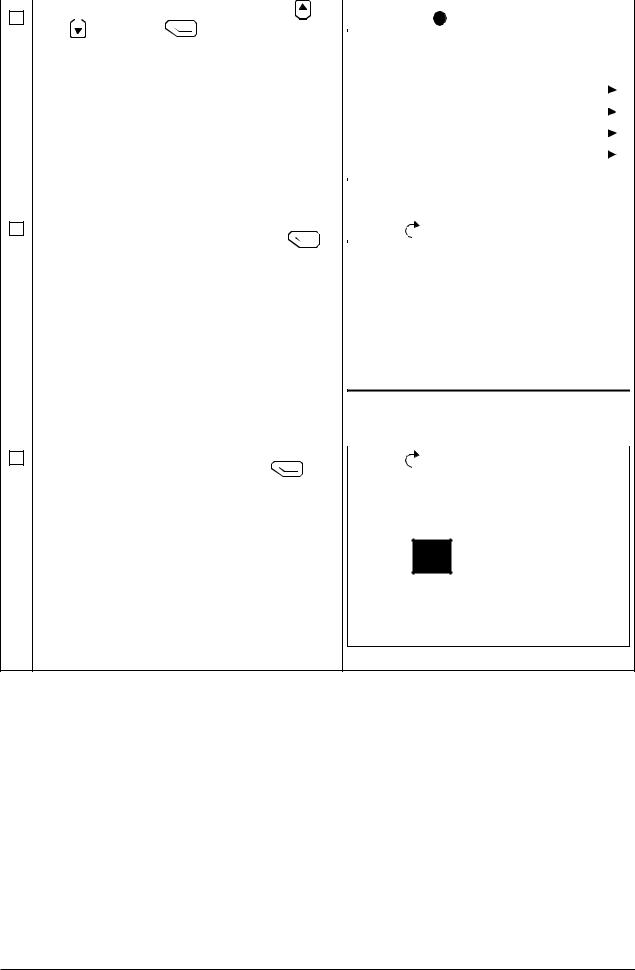
Highlight Settings on the menu using |
|
|
|
|
|
||||||
Remote |
x |
ACS880 |
0.0 rpm |
||||||||
and |
and press |
(Select). |
|
|
|
|
|
|
|
|
|
|
|
Settings |
|
|
|
|
|
|
|||
|
|
|
|
|
|
|
|
|
|
|
|
|
|
|
|
|
|
|
|
|
|
||
|
|
|
|
|
|
|
|
|
|
|
|
|
|
|
|
|
Language |
|
|
|
|
|
|
|
|
|
|
|
Date & time |
|
|
|
|
||
|
|
|
|
|
Edit texts |
|
|
|
|
|
|
|
|
|
|
|
Display settings |
|
|
|
|||
|
|
|
|
|
Reset to defaults |
|
|
|
|||
|
|
|
|
|
|
|
|
|
|||
|
|
|
|
Back |
|
12:34 |
Select |
||||
|
|
|
|
|
|
|
|
|
|
|
|
In the Settings menu, highlight Date & time |
|
|
|
|
|
||||||
Remote |
|
|
0.0 rpm |
||||||||
(if not already highlighted) and press |
|
|
|
|
|
|
|
|
|
||
|
|
Date & time |
|
|
|
|
|||||
(Select). |
|
|
|
|
|
|
|
||||
|
|
|
|
|
|
|
|||||
|
|
|
|
|
|
|
|
|
|
||
|
|
|
|
|
Date |
|
|
01.01.1980 |
|
|
|
|
|
|
|
|
Time |
|
|
12:34:56 |
|
|
|
|
|
|
|
|
Show date as |
day.month.year |
|
||||
|
|
|
|
|
Show time as |
|
24-hour |
|
|||
|
|
|
|
|
Daylight saving |
EU |
|
||||
|
|
|
|
|
Next daylight saving start |
28.03. |
|
|
|||
|
|
|
|
Back |
|
12:35 |
Edit |
|
|||
|
|
|
|
|
|
|
|
|
|
|
|
In the Date & time menu, highlight Date (if |
|
|
|
|
|
||||||
Remote |
|
|
0.0 rpm |
||||||||
not already highlighted) and press |
|
|
|
|
|
|
|
|
|
||
|
|
Date |
|
|
|
|
|
||||
(Select). |
|
|
|
|
|
|
|
|
|||
|
|
|
|
|
|
|
|
|
|
||
Day Month Year
01.01.1980 |
Tuesday
Cancel |
12:35 |
Save |
20 Start-up
Set the correct date:
•Use 
 and
and 
 to move the cursor left and right.
•Use  and
and 
 to change the value.
•Press  (Save) to accept the new setting.
Check/adjust all the remaining settings in the
Date & time menu.
The Show clock setting determines whether the time is shown at all times in the bottom pane of the display.
After you have made the settings, press  (Back or Exit) repeatedly until the
Home view (right) reappears.
Remote |
ACS880 |
0.0 rpm |
Motor speed used |
0.00 |
|
rpm |
|
|
Motor current |
0.00 |
|
A |
|
|
Motor torque |
0.0 |
|
% |
|
|
Options |
12:34 |
Menu |
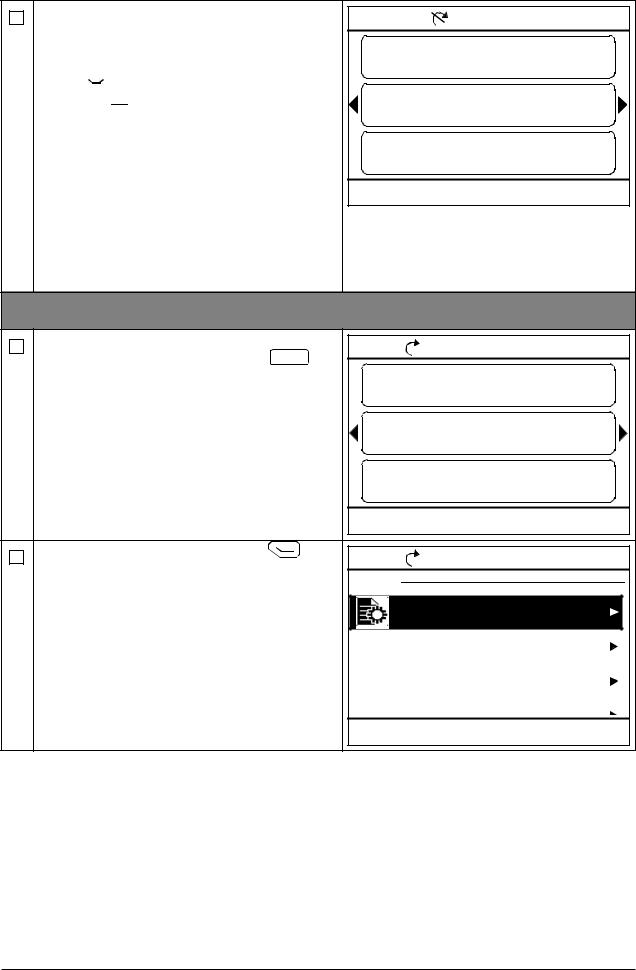
2 – Supply voltage and motor data settings |
|
|||
Switch to local control to ensure that external |
Local |
|
|
0.0 rpm |
control is disabled by pressing the Loc/Rem |
rpm |
|
|
0.00 |
“Local” in the top pane. |
|
|
||
key. Local control is indicated by the text |
Motor speed used |
0.00 |
||
|
A |
|
|
|
|
Motor current |
|
0.0 |
|
|
% |
|
|
|
|
Motor torque |
|
|
|
|
Options |
12:36 |
Menu |
|
Open the main Menu by pressing |
Local |
|
|
0.0 rpm |
(Menu). |
Menu |
|
|
|
|
|
|
|
|
|
|
Parameters |
|
|
|
|
Assistants |
|
|
|
|
Energy efficiency |
|
|
|
Exit |
Event log 12:36 |
Select |
|
|
|
|
|
|
|
|
|
|
|
|
|
|
|
Start-up 21 |
|||
|
|
|
|
|
|
|
|
|
|
|
|
|
|
||||
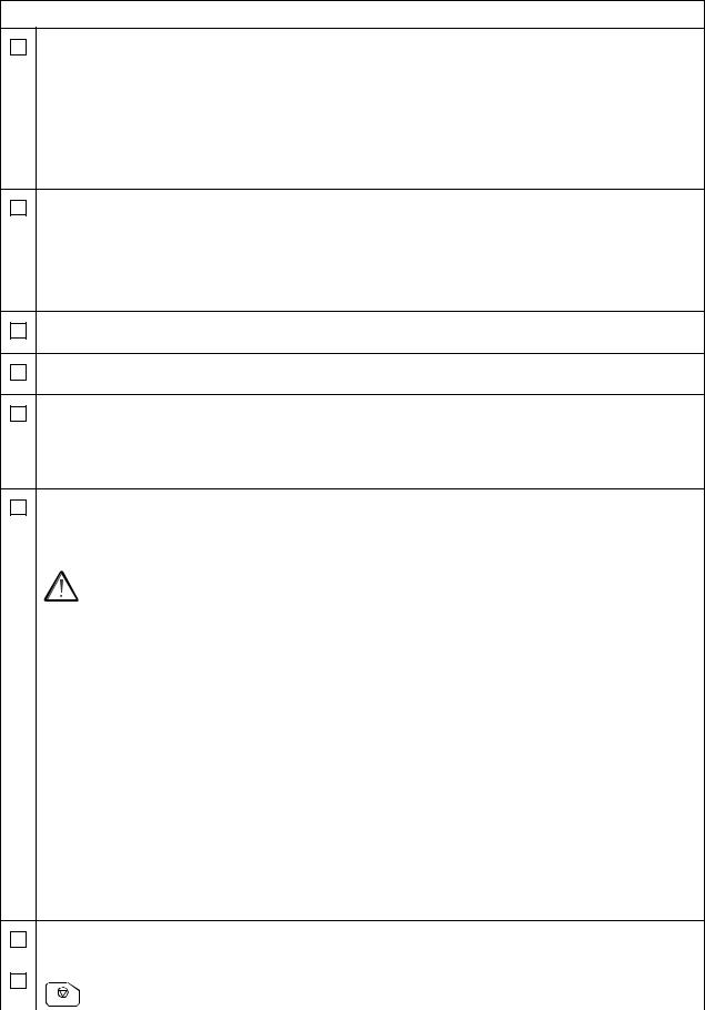
Highlight Parameters and press |
|
|
|
|
|
|
|
|
|
|
|
|
|||||
|
|
Local |
|
|
x ACS880 |
0.0 rpm |
|||||||||||
|
|
|
|||||||||||||||
|
|
|
|||||||||||||||
(Select). |
|
|
|
|
|
|
|
|
|
|
|
|
|
|
|
|
|
|
|
|
|
Parameters |
|
|
|
|
|
|
|
|
|||||
|
|
|
|
|
|
|
|
|
|
|
|
|
|||||
|
|
|
|
|
|
|
|
|
|
|
|
|
|||||
|
|
|
|
|
|
|
|
|
|
|
|
|
|
|
|
|
|
|
|
|
|
|
Complete list |
|
|
|
|
|
|
||||||
|
|
|
|
|
By function |
|
|
|
|
|
|
||||||
|
|
|
|
|
Favorites |
|
|
|
|
|
|
|
|
|
|||
|
|
|
|
|
Modified |
|
|
|
|
|
|
|
|
|
|||
|
|
|
|
|
|
|
|
|
|
|
|
|
|
|
|
|
|
|
|
|
|
|
Back |
|
|
|
12:36 |
|
Select |
||||||
|
|
|
|
|
|
|
|
|
|
|
|
|
|
|
|
|
|
Highlight Complete list using |
and |
|
|
|
|
|
|
|
|
|
|
||||||
Local |
|
|
|
|
|
0.0 rpm |
|||||||||||
and press |
(Select). |
|
|
|
|
|
|
|
|
|
|
|
|
|
|
|
|
|
|
|
Complete list |
|
|
|
|
|
|
|
|||||||
A listing of parameter groups is displayed. |
|
|
|
|
|
|
|
||||||||||
|
|
|
|
|
|
|
|||||||||||
|
|
|
|
|
|
|
|
|
|
|
|
|
|||||
|
|
|
|
|
01 |
Actual values |
|
|
|
|
|||||||
|
|
|
|
|
03 |
Input references |
|
|
|
|
|||||||
|
|
|
|
|
04 |
Warnings and faults |
|
|
|
|
|||||||
|
|
|
|
|
05 |
Diagnostics |
|
|
|
|
|
|
|||||
|
|
|
|
|
06 |
Control and status words |
|
|
|||||||||
|
|
|
|
|
07 |
System info |
12:36 |
|
Select |
|
|
||||||
|
|
|
|
|
Back |
|
|
|
|
|
|
||||||
|
|
|
|
|
|
|
|
|
|
|
|
|
|
|
|
|
|
Highlight parameter group 95 HW |
|
|
|
|
|
|
|
|
|
|
|||||||
|
|
Local |
|
|
|
|
ACS880 |
0.0 rpm |
|||||||||
|
|
|
|
|
|
||||||||||||
configuration and press |
(Select). |
|
|
|
|
|
|
|
|
|
|
|
|
|
|
||
|
95 HW configuration |
|
|
|
|
|
|||||||||||
Note that the list wraps around in either |
|
|
|
|
|
||||||||||||
|
|
|
|
|
|||||||||||||
|
|
|
|
|
|
|
|
|
|
|
|
|
|||||
direction between groups 99 and 01. In this |
95.01 Supply voltage |
Not given |
|
|
|
||||||||||||
case, it is quicker to use |
to locate group |
95.04 Control board supply Internal 24 V |
|
|
|
||||||||||||
95 on the list. |
|
|
|
|
95.08 DC switch monitoring |
Disable |
|||||||||||
After selecting a group, a listing of |
|
|
95.15 Special HW settings |
0000 |
|
|
|||||||||||
parameters within the group is displayed. |
95.20 HW option wor... |
...0 0000 0000 |
|
|
|||||||||||||
|
Back |
|
12:36 |
Edit |
Highlight parameter 95.01 Supply voltage (if |
Local |
|
|
0.0 rpm |
not already highlighted) and press |
95.01 |
Supply voltage |
|
|
(Edit). |
|
|||
The available parameter settings are listed. |
[0] |
Not given |
|
|
|
[1] 208…240 V |
|
||
|
[2] 380…415 V |
|
||
|
[3] 440…480 V |
|
||
|
[4] |
500 V |
|
|
|
Cancel |
12:36 |
Save |
|

22 Start-up
Highlight the correct setting on the list and |
|
|
|
|
|
|||||||
Local |
|
ACS880 |
0.0 rpm |
|||||||||
|
||||||||||||
press |
(Save). |
|
|
|||||||||
|
|
95 HW configuration |
|
|
|
|
|
|
||||
|
|
|
|
|
|
|
|
|
|
|||
|
|
|
|
|
|
|
|
|
||||
|
|
|
|
|
|
|
|
|
|
|
|
|
|
|
|
|
95.01 Supply voltage |
380...415 V |
|
|
|
|
|||
|
|
|
95.04 Control board supply Internal 24 V |
|
|
|
|
|||||
|
|
|
|
95.08 DC switch monitoring |
Disable |
|
||||||
|
|
|
|
95.15 Special HW settings |
0000 |
|
|
|||||
|
|
|
|
95.20 HW option wor... |
...0 0000 0000 |
|
||||||
|
|
|
|
|
|
|
|
|
|
|||
|
|
|
Back |
12:36 |
|
Edit |
||||||
Press  (Back) to display the list of parameter groups again. Select parameter group
99 Motor data, and set parameter 99.03 Motor type.
Set parameter 99.04 Motor control mode.
DTC = Direct torque control; Scalar
DTC is suitable for most cases. Scalar mode is recommended if
•the nominal current of the motor is less than 1/6 of the nominal current of the drive,
•the drive is used for test purposes with no motor connected, or
•the drive controls multiple motors and the number of motors connected is variable.
Refer to the motor nameplate for the following parameter settings. Whenever possible, enter the values exactly as shown on the motor nameplate.
Example of a nameplate of an induction |
Example of a nameplate of a permanent |
(asynchronous) motor: |
magnet motor: |
|
|
|
ABB Motors |
|
|
|
ABB Motors |
||||||
3 |
motor |
|
M2AA 200 MLA 4 |
|
|
3 ~ motor |
|
M2BJ 280SMB 10 B3 |
|
||||
|
|
|
|
|
|
|
|
|
|||||
|
|
|
IEC 200 M/L 55 |
|
|
S1 SPEC INSUL. |
|
No 3424522 |
|||||
|
|
|
|
No |
|
|
|
||||||
|
|
|
|
|
|
JK-21640-1 |
|
|
Ins.cl. F |
IP 55 |
|||
|
|
|
|
|
Ins.cl. |
F |
IP 55 |
|
|
||||
|
|
|
|
|
|
|
|
|
|||||
V |
|
Hz |
kW |
r/min |
A |
cos |
IA/IN t E/s |
V |
Hz |
kW |
r/min |
A |
cos M IA/IN t E/s |
690 |
Y |
50 |
30 |
1475 |
32.5 |
0.83 |
|
|
|
|
|
|
|
400 |
D |
50 |
30 |
1475 |
56 |
0.83 |
|
400 D |
50 |
55 |
600 |
103 |
0.97 |
660 |
Y |
50 |
30 |
1470 |
34 |
0.83 |
|
|
|
|
|
|
|
380 |
D |
50 |
30 |
1470 |
59 |
0.83 |
|
Prod. code |
2GBJ285220-ADA405445477 |
||||
415 |
D |
50 |
30 |
1475 |
54 |
0.83 |
|
6316/C3 |
|
|
|
630kg |
|
440 |
D |
60 |
35 |
1770 |
59 |
0.83 |
|
|
|
6316/C3 |
|||
Cat. no |
3GAA 202 001 - ADA |
|
|
|
|
|
|
|
|
||||
|
6312/C3 |
|
6210/C3 |
|
180 |
|
|
|
|
|
IEC 34-1 |
||
|
|
|
|
|
|
|
|
|
|||||
|
|
|
|
|
|
IEC 34-1 |
|
|
|
|
|
|
|
99.06 Motor nominal current
The allowable range is
•in DTC mode: 1/6 × IHd … 2 × IHd of the drive
•in Scalar mode: 0 … 2 × IHd
Note: With numerical parameter values:
•Use  and
and 
 to change the value of a digit.
•Use 
 and
and 
 to move the cursor left and right.
•Press  (Save) to enter the value.
Start-up 23
Make the following parameter settings in the same manner.
99.07 Motor nominal voltage
The allowable range is 1/6 × UN … 2 × UN of the drive.
With permanent magnet motors, the nominal voltage is the BackEMF voltage at nominal speed. If the voltage is given in volt/rpm (eg. 60 V per 1000 rpm), the voltage at a nominal speed of 3000 rpm is 3 × 60 V = 180 V. Note that nominal voltage is not the same as equivalent DC motor voltage (EDCM) given by some manufacturers. The nominal voltage can be calculated by dividing the EDCM voltage by 1.7 (or square root of 3).
99.08 Motor nominal frequency
With permanent magnet motors, if the nominal frequency is not shown on the nameplate, it can be calculated using the following formula:
f = n × p / 60
where n = nominal motor speed, p = number of pole pairs.
99.09Motor nominal speed
99.10Motor nominal power
99.11Motor nominal cos Φ
99.12Motor nominal torque
These values are not required, but can be entered to improve control accuracy. If you do not know the correct values, leave the parameters at 0. DO NOT enter estimated values.
99.13 ID run requested
This parameter selects the mode of the identification run (DTC motor control mode only). Note: The drive must be in local control for the identification run.
WARNING! The identification run modes marked thus * will run the motor in the forward direction (see below for details). Make sure it is safe to run the motor
before choosing any of these modes.
*Normal mode should be selected whenever possible.. The driven machinery must be decoupled from the motor if
•the load torque is higher than 20%, or
•the machinery is not able to withstand the nominal torque transient during the
identification run.
*Reduced mode should be selected if the mechanical losses are higher than 20%, ie. the load cannot be de-coupled, or full flux is required to keep the motor brake open (eg. with conical motors).
The Standstill mode should be selected if neither the *Normal or *Reduced mode can be used. Notes:
•This mode cannot be used with a permanent magnet motor if the load torque is higher than 20% of nominal.
•Mechanical brake is not opened by the logic for the identification run.
Ensure that the Safe torque off and emergency stop circuits (if present) are closed.
Start the identification run by pressing the |
A warning will indicate that the |
(Start) button. |
identification run is in progress. |
|
|
|
|

24 Start-up
Check that the motor runs in the correct direction (forward direction shown below).
The identification run has completed when the drive stops and the value of parameter 99.13 reverts to None.
If the motor ran in the wrong direction, correct the motor cabling or adjust parameter
99.16 Motor phase order.

Control locations and operating modes 25
4
Control locations and operating modes
What this chapter contains
This chapter describes the control locations and operating modes supported by the control program.
26 Control locations and operating modes
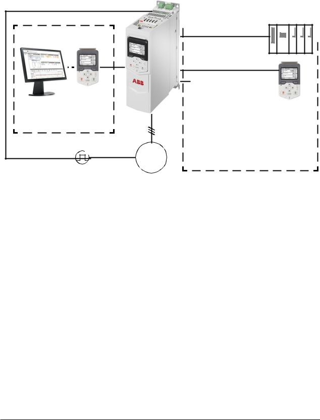
Local control vs. external control
The ACS880-M04 has two main control locations: external and local. The control location is selected with the Loc/Rem key on the control panel or in the PC tool.
ACS880-M04 |
2) |
Local control |
Control panel or Drive |
composer PC tool (optional) |
M |
3~ |
Encoder |
|
|
|
|
|
|
|
|
|
|
|
|
|
|
|
|
|
|
|
|
|
|
|
|
|
|
|
|
|
|
|
I/O 1) |
|
External control |
|
|
|
|
|
|
||||||||||||||||
|
|
|
|
|
|
|
|
|
|||||||||||||||||||
|
|
|
|
|
|
|
|
|
|
|
|
|
|
PLC |
|
|
|
|
|
|
|||||||
|
|
|
|
|
|
|
|
|
|
|
|
|
|
|
|
|
|
|
|
||||||||
|
|
|
|
|
|
|
|
|
|
|
|
|
|
|
|
|
|
|
|||||||||
|
|
|
|
|
|
|
|
|
|
|
|
|
|
|
|
|
|
|
|
||||||||
|
|
|
|
|
|
|
|
|
|
|
|
|
|
|
|
|
|
|
|
|
|
|
|
|
|
|
|
|
|
|
|
|
|
|
|
|
|
|
|
|
|
|
|
|
|
|
|
|
|
|
|
|
|
|
|
|
|
|
|
|
|
|
|
|
|
|
|
|
|
|
|
|
|
|
|
|
|
|
|
|
|
|
|
Fieldbus adapter (Fxxx)
Embedded fieldbus interface (EFB) or master/follower link
Control panel
1)Extra inputs/outputs can be added by installing optional I/O extension modules (FIO-xx) in drive slots.
2)Encoder or resolver interface module(s) (FEN-xx) installed in drive slots.
Local control
The control commands are given from the control panel keypad or from a PC equipped with Drive composer when the drive is set to local control. Speed and torque control modes are available for local control; frequency mode is available when scalar motor control mode is used (see parameter 19.16 Local control mode).
Local control is mainly used during commissioning and maintenance. The control panel always overrides the external control signal sources when used in local control. Changing the control location to local can be prevented by parameter 19.17 Local control disable.
The user can select by a parameter (49.05 Communication loss action) how the drive reacts to a control panel or PC tool communication break. (The parameter has no effect in external control.)

Control locations and operating modes 27
External control
When the drive is in external control, control commands are given through
•the I/O terminals (digital and analog inputs), or optional I/O extension modules
•the embedded fieldbus interface or an optional fieldbus adapter module
•the master/follower link, and/or
•the control panel.
Two external control locations, EXT1 and EXT2, are available. The user can select the sources of the start and stop commands separately for each location by parameters 20.01…20.10. The operating mode can be selected separately for each location (in parameter group 19 Operation mode), which enables quick switching between different operating modes, for example speed and torque control. Selection between EXT1 and EXT2 is done via any binary source such as a digital input or fieldbus control word (see parameter 19.11 Ext1/Ext2 selection). The source of reference is selectable for each operating mode separately.
Using the control panel as an external control source
The control panel can also be used as a source of start/stop commands and/or reference in external control. Selections for the control panel are available in the start/stop command source and reference source selection parameters.
Reference source selection parameters have two selections for the control panel. The difference between the two selections is in the initial reference value after the reference source switches to the control panel.
The panel reference is saved whenever another reference source is selected. If the reference source selection parameter is set to Control panel (ref saved), the saved value is used as the initial reference when control switches back to the panel. Note that only one type of reference can be saved at a time: for example, attempting to use the same saved reference with different operating modes (speed, torque, etc.) causes the drive to trip on 7083 Panel reference conflict. The panel reference can be separately limited by parameters in group 49 Panel port communication.
With the reference source selection parameter set to Control panel (ref copied), the initial panel reference value depends on whether the operating mode changes with the reference source. If the source switches to the panel and the operating mode does not change, the last reference from the previous source is adopted. If the operating mode changes, the drive actual value corresponding to the new mode is adopted as the initial value.
28 Control locations and operating modes
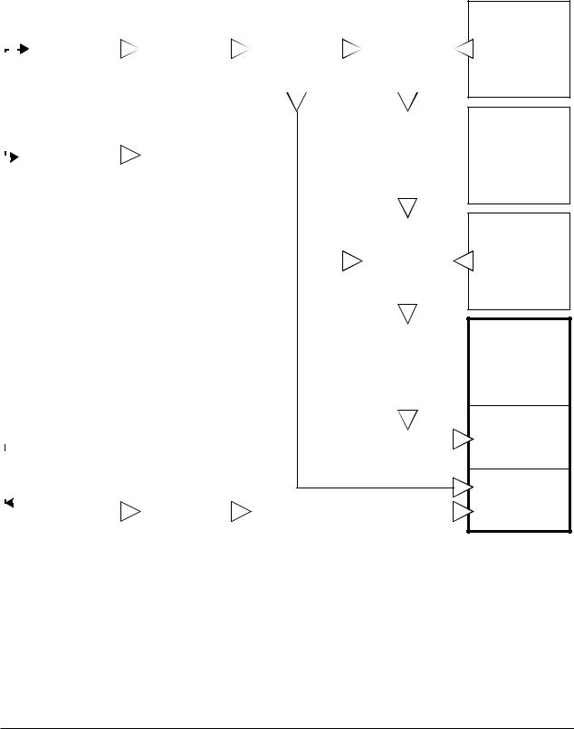
Operating modes of the drive
The drive can operate in several operating modes with different types of reference. The mode is selectable for each control location (Local, EXT1 and EXT2) in parameter group 19 Operation mode.
The following is a general representation of the reference types and control chains. The page numbers refer to detailed diagrams in chapter Control chain diagrams.
|
|
|
Speed |
|
|
Speed reference |
|
|
Speed reference |
|
Speed error |
|||
|
|
|
reference |
|
|
source selection |
|
|
ramping and |
|
calculation |
|||
|
|
|
source selection |
|
|
II |
|
|
shaping |
|
(p 571) |
|||
|
|
|
I |
|
|
(p 567) |
|
|
(p 568) |
|
|
|
|
|
|
|
|
(p 566) |
|
|
|
|
|
|
|
|
|
|
|
|
|
|
|
|
|
|
|
|
|
|
|
|
|
|
|
|
|
|
|
|
|
|
|
|
|
|
|
|
|
|
|
|
|
|
|
|
|
|
|
|
|
|
|
|
|
|
|
|
|
|
|
|
|
|
|
|
|
|
|
|
|
|
|
|
|
|
|
|
|
|
|
|
|
|
|
|
|
|
|
|
|
|
|
|
|
|
|
|
|
|
|
|
Torque |
|
|
|
|
|
|
|
|
Speed controller |
||
|
|
|
|
|
|
|
|
|
|
|
||||
|
|
|
|
|
|
|
|
|
|
|
||||
|
|
|
reference |
|
|
|
|
|
|
|
|
(p 572) |
||
|
|
|
|
|
|
|
|
|
|
|
||||
|
|
|
source selection |
|
|
|
|
|
|
|
|
|
|
|
|
|
|
|
|
|
|
|
|
|
|
|
|
|
|
|
|
|
and modification |
|
|
|
|
|
|
|
|
|
|
|
|
|
|
|
|
|
|
|
|
|
|
|
|
|
|
|
|
|
(p 573) |
|
|
|
|
|
|
|
|
|
|
|
|
|
|
|
|
|
|
|
|
|
|
|
|
|
|
|
|
|
|
|
|
|
|
|
|
|
|
|
|
|
|
|
|
|
|
|
|
|
|
|
|
|
|
|
|
|
|
|
|
|
|
|
|
|
|
|
|
|
|
|
|
|
|
|
|
|
|
|
|
|
|
|
|
|
|
|
|
|
|
|
|
|
|
|
|
|
|
Reference |
||
|
|
|
|
|
|
|
|
|
|
|
|
|||
|
|
|
|
|
|
|
|
|
|
|
|
|||
|
|
|
|
|
|
|
|
|
|
|
|
selection for |
||
|
|
|
|
|
|
|
|
|
|
|
|
|||
|
|
|
|
|
|
|
|
|
|
|
|
|||
|
|
|
|
|
|
|
|
|
|
|
|
torque controller |
||
|
|
|
|
|
|
|
|
|
|
|
|
|||
|
|
|
|
|
|
|
|
|
|
|
|
|||
|
|
|
|
|
|
|
|
|
|
|
|
(p 575) |
||
|
|
|
|
|
|
|
|
|
|
|
|
|||
|
|
|
|
|
|
|
|
|
|
|
|
|||
|
|
|
|
|
|
|
|
|
|
|
|
|
|
|
|
|
|
|
|
|
|
|
|
|
|
|
|
|
|
|
|
|
|
|
|
|
|
|
|
|
|
|
|
|
|
|
|
|
|
|
|
|
|
|
|
|
|
|
|
|
|
|
|
|
|
|
|
|
|
|
|
|
|
|
|
|
|
|
|
|
|
|
|
|
|
|
|
|
|
|
|
|
|
|
|
|
|
|
|
|
|
Torque limitation |
||
|
|
|
|
|
|
|
|
|
|
|
|
|||
|
|
|
|
|
|
|
|
|
|
|
|
|||
|
|
|
|
|
|
|
|
|
|
|
|
(p 576) |
||
|
|
|
|
|
|
|
|
|
|
|
|
|||
|
|
|
|
|
|
|
|
|
|
|
|
|
|
|
|
|
|
|
|
|
|
|
|
|
|
|
|
|
|
|
|
|
|
|
|
|
|
|
|
|
|
|
|
|
|
|
|
|
|
|
|
|
|
|
|
|
|
|
|
|
|
|
|
|
|
|
|
|
|
|
|
|
|
|
|
|
|
|
|
|
|
|
|
|
|
|
|
|
|
|
|
|
|
|
|
|
|
|
|
|
|
|
|
|
|
|
|
|
|
|
|
|
|
|
|
|
|
|
|
|
|
|
|
|
|
|
|
|
|
|
|
|
|
|
|
|
|
|
|
|
|
|
|
|
|
|
|
|
|
|
|
|
|
|
|
|
|
|
|
|
|
|
|
|
|
|
|
|
|
|
|
|
|
|
|
|
|
|
|
|
|
|
|
|
|
|
|
|
|
|
|
|
|
|
|
|
|
|
|
|
|
|
|
|
|
|
|
|
Frequency |
|
Frequency |
|
|
|
|
|
|
|
|||
|
|
|
|
|
|
|||
|
|
|
|
|
reference |
|
reference |
|
|
|
|
|
|
|
|||
|
|
|
|
|
|
|||
|
|
|
|
|
source selection |
|
modification |
|
|
|
|
|
|
|
|||
|
|
|
|
|
and modification |
|
(p 579) |
|
|
|
|
|
|
(p 578) |
|
|
|
|
|
|
|
|
|
|
|
|
Motor feedback configuration
(p 569)
Load feedback and position counter configuration
(p 570)
Operating mode selection
(p 574)
Torque controller
(p 577)
DTC motor control mode
Scalar motor control mode

Control locations and operating modes 29
Speed control mode
The motor follows a speed reference given to the drive. This mode can be used either with estimated speed as feedback, or with an encoder or resolver for better speed control accuracy.
Speed control mode is available in both local and external control. It is also available both in DTC (Direct Torque Control) and scalar motor control modes.
Torque control mode
Motor torque follows a torque reference given to the drive. Torque control is possible without feedback, but is much more dynamic and accurate when used in conjunction with a feedback device such as an encoder or a resolver. It is recommended that a feedback device is used in crane, winch or lift control situations.
Torque control mode is available in DTC motor control mode for both local and external control locations.
Frequency control mode
The motor follows a frequency reference given to the drive. Frequency control is only available in scalar motor control mode.
Special control modes
In addition to the control modes mentioned above, the following special control modes are available:
•Emergency stop modes Off1 and Off3: Drive stops along the defined deceleration ramp and drive modulation stops.
•Jogging mode: Drive starts and accelerates to the defined speed when the jogging signal is activated. For more information, see section Jogging (page 57).

30 Control locations and operating modes
Loading...