


 Loading...
—
ABB MEASUREMENT & ANALY TICS
Pressductor Pillowblock Load Cells Vertical Measuring PFCL 201
User manual
3BSE023881R0101 en Rev I

USE OF SYMBOLS
This publication includes the following symbols with information regarding safety or other important information:
CAUTION
Caution icon indicates important information. Risk of damage to equipment, property or software.
DANGER
Danger icon indicates a hazard which could result in personal injury or even death.
ELECTRICAL
Electrical warning icon indicates the presence of a hazard which could result in electrical shock.
ESD
ESD icon indicates that electrostatic discharge precautions are needed.
Information
Information icon alerts the reader to relevant facts and conditions.
Tip
Tip icon advise how to design your product or how to use a certain function.
NOTICE
The information in this document is subject to change without notice and should not be construed as a commitment by ABB AB. ABB AB assumes no responsibility for any errors that may appear in this document.
In no event shall ABB AB be liable for direct, indirect, special, incidental or consequential damages of any nature or kind arising from the use of this document, nor shall ABB AB be liable for incidental or consequential damages arising from use of any software or hardware described in this document.
This document and parts thereof must not be reproduced or copied without ABB AB’s written permission, and the contents thereof must not be imparted to a third party nor be used for any unauthorized purpose.
The software described in this document is furnished under a license and may be used, copied, or disclosed only in accordance with the terms of such license.
CE-marking
This product meets the requirements spec fied in the RoHS directive 2011/65/EU and EMC directive 2014/30/EU provided that the installation is carried out in accordance with the instructions given in this manual.
© Copyright 20042020 ABB. All rights reserved.

2Table of Contents
1Introduction
1.1 |
About this Manual......................................................................................... |
5 |
1.2 |
Disposal and Recycling................................................................................. |
5 |
1.2.1 |
Environmental Policy..................................................................................... |
5 |
1.2.2 |
Recycling Electrical and Electronic Equipment, WEEE................................... |
5 |
1.2.3 |
Recycling the Transport Material................................................................... |
6 |
1.2.4 |
Disposal of the Product................................................................................. |
6 |
1.3 |
Function and Design..................................................................................... |
6 |
1.3.1 |
General......................................................................................................... |
6 |
1.3.2 |
Load Cells PFCL 201.................................................................................... |
7 |
1.3.3 |
Principle of Measurement.............................................................................. |
7 |
2Description
2.1 |
General......................................................................................................... |
9 |
2.2 |
Technical Data............................................................................................ |
10 |
2.3 |
efin t ons................................................................................................... |
11 |
2.4 |
Measuring principle of the sensor................................................................ |
14 |
2.5 |
Mounting Arrangement............................................................................... |
14 |
2.5.1 |
Coordinate System..................................................................................... |
14 |
2.5.2 |
Horizontal Mounting.................................................................................... |
15 |
2.5.3 |
Inclined Mounting........................................................................................ |
16 |
2.6 |
The Electrical Circuit................................................................................... |
17 |
3Installation
3.1 |
General ...................................................................................................... |
18 |
3.2 |
Unpacking.................................................................................................. |
18 |
3.3 |
Preparations............................................................................................... |
18 |
3.4 |
Mounting ................................................................................................... |
19 |
3.5 |
Cabling for Load Cell PFCL 201CE............................................................. |
20 |

4Commissioning
4.1 |
General....................................................................................................... |
22 |
4.2 |
Preparatory Calculations............................................................................. |
22 |
5Maintenance
5.1 |
General....................................................................................................... |
23 |
5.2 |
Preventive Maintenance.............................................................................. |
23 |
5.3 |
Spare Parts................................................................................................. |
23 |
6Fault Tracing
6.1 |
General....................................................................................................... |
25 |
6.2 |
Interchangeability........................................................................................ |
25 |
6.3 |
Fault Tracing Procedure.............................................................................. |
25 |
6.4 |
Fault Tracing in the Mechanical Installation.................................................. |
26 |
6.4.1 |
Defective Mounting Surface, Support or Adapter Plates.............................. |
26 |
6.4.2 |
Force Shunting........................................................................................... |
26 |
6.4.3 |
Fastening of Load cell and Adapter Plates.................................................. |
26 |
6.4.4 |
Rolls and Bearings...................................................................................... |
26 |
6.4.5 |
Driven Roll.................................................................................................. |
26 |
6.5 |
Fault Tracing of Load Cells, Junction Boxes and wiring............................... |
27 |
ADrawings
A.1 |
Load Cell PFCL 201C, Dimension Drawing................................................. |
29 |
A.2 |
Load Cell PFCL 201CE, Dimension Drawing............................................... |
30 |
A.3 |
Load Cell PFCL 201CD, Dimension Drawing............................................... |
31 |
A.4 |
Adapter Plate Upper PFCL 201, Dimension Drawing................................... |
32 |
A.5 |
Adapter Plate Lower PFCL 201, Dimension Drawing................................... |
33 |
|
Alphabetical index |
|
Pressductor PillowBlock Load Cells, Vertical Measuring PFCL 201, User Manual
1 Introduction
1 Introduction
1.1 |
About this Manual |
||
|
This manual describes the load cells PFCL 201C/201CE/201CD in a Pressductor® Strip Tension |
||
|
Measuring System. |
||
|
The purpose of this manual is to describe the general function and design of the load cells and also |
||
|
to be a guidance at installation, commissioning, preventive maintenance and fault tracing. |
||
1.2 |
Disposal and Recycling |
||
1.2.1 |
Environmental Policy |
||
|
ABB is committed to its environmental policy. We strive continuously to make our products envi- |
||
|
ronmentally more sound by applying results obtained in recyclability and life cycle analyses. Prod- |
||
|
ucts, manufacturing process as well as logistics have been designed taking into account the envi- |
||
|
ronmental aspects. |
||
|
Our environmental management system, cert fied to ISO 14001, is the tool for carrying out our |
||
|
environmental policy. However it is on the customer’s responsibility to ensure that local legislation is |
||
|
followed. |
||
1.2.2 |
Recycling Electrical and Electronic Equipment, WEEE |
||
|
|
|
|
|
|
|
|
The crossed – out wheeled bin symbol on the product(s) and / or accompanying documents means that used electrical and electronic equipment (WEEE) should not be mixed with general household waste.
If you wish to discard electrical and electronic equipment (EEE), in the European Union, please contact your dealer or supplier for further information.
Outside of the European Union, contact your local authorities or dealer and ask for the correct method of disposal.
3BSE023881R0101 en Rev I |
5 |

|
Pressductor PillowBlock Load Cells, Vertical Measuring PFCL 201, User Manual |
|
1 Introduction |
|
|
|
Disposing of this product correctly will help save valuable resources and prevent any potential neg- |
|
ative effects on human health and the environment, which could otherwise arise from inappropriate |
|
waste handling. |
1.2.3 |
Recycling the Transport Material |
|
ABB designs all transport material to be recyclable where practical. The recycling of the transport |
|
material depends on the material type and availability of local recycling programs. |
|
After receiving the system into the site, the package and the transportation locking have to be |
|
removed. Recycle the transport material according to local regulations. |
1.2.4 |
Disposal of the Product |
|
When the product is to be disposed, it should be dismantled and the components recycled |
|
according to local regulations. |
1.2.4.1 |
Dismantling and Recycling of the Product |
|
Dismantle and recycle the components of the product according to local regulations. |
|
|
|
CAUTION |
|
Some of the components are heavy! The person who performs the dismantling of |
|
the system must have the necessary knowledge and skills to handle heavy |
|
components to avoid the risk of accidents and injury from occurring. |
|
|
|
• Load cell: These parts are made of structural steel, which can be recycled according to |
|
local instructions. All the auxiliary equipment, such as cabling or hoses must be removed |
|
before recycling the material. |
1.3 |
Function and Design |
1.3.1 |
General |
|
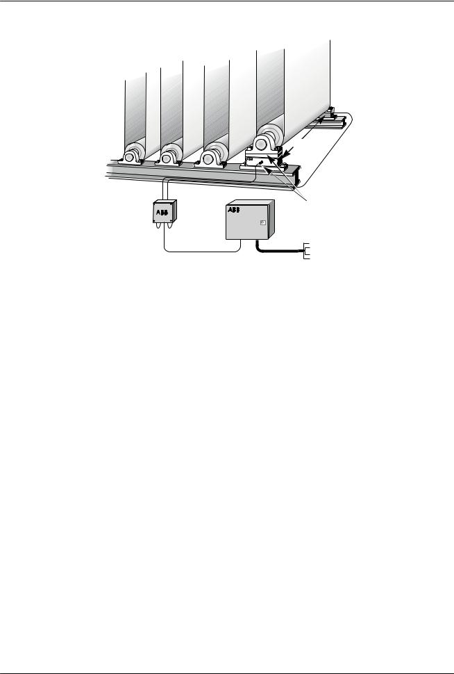
A complete measuring system normally consists of two load cells, a junction box, one control unit |
|
with two measurement channels and cabling. |
6 |
3BSE023881R0101 en Rev I |
Pressductor PillowBlock Load Cells, Vertical Measuring PFCL 201, User Manual
1 Introduction
Load cells
Load cell cabling |
|
|
Adapter plates |
Junction box |
Control unit |
|
Output signals |
|
A |
|
INDIVIDUELL A |
|
UMMATION A+B |
|
Sum A+B |
|
IFFERENS A-B |
|
Differential A-B |
|
INDIVIDUELL B |
|
B |
|
Figure 1. Complete Measuring System |
1.3.2 |
Load Cells PFCL 201 |
|
The load cells are installed under the roll bearings, where they measure forces at right angles to the |
|
mounting surface. |
|
The reactive force from the strip, which is proportional to the strip tension, is transferred to the load |
|
cells via the roll and the bearings. |
|
The load cells are connected to the control unit via a junction box. The control unit converts the |
|
load cell signals to DC voltages that are proportional to the reaction force. Depending on which |
|
control unit is chosen, it is possible to have the analog signals for the two individual load cells (A |
|
and B), the sum of the load cell signals (A+B), and/or the difference between the load cell signals |
|
(A-B). |
1.3.3 |
Principle of Measurement |
|
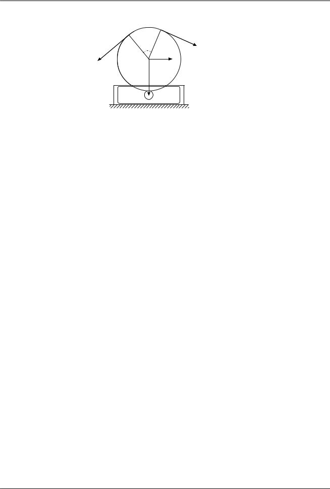
The load cell only measures force in the direction FR. The measurement force may be positive or |
|
negative. The load cell is normally installed under the roll bearings. When there is a strip in tension |
|
over the roll, the tension (T) gives rise to two force components, one in the direction of measure- |
ment of the load cell (FR) and one at right angles (FV).
The measuring force depends on the relationship between the tension (T) and the wrap angle formed by the strip around the measuring roll.
3BSE023881R0101 en Rev I |
7 |
Pressductor PillowBlock Load Cells, Vertical Measuring PFCL 201, User Manual
1 Introduction
Wrap |
|
angle |
T |
|
T |
FV |
|
FR |
Figure 2. Measuring Roll with Force Vectors
8 |
3BSE023881R0101 en Rev I |
Pressductor PillowBlock Load Cells, Vertical Measuring PFCL 201, User Manual
2 Description
2 Description
2.1 General
The load cell is machined from a single piece of stainless steel. The sensors are machined directly in the piece of steel and are positioned so that they are sensitive to force in the direction of measurement and insensitive in other directions.
The load cell is mounted on a base with four screws, and the bearing housing is mounted on top of the load cell with four screws.
Every load cell comes calibrated and temperature compensated.
The load cells PFCL 201C/201CE/201CD are available in four measurement ranges, all variants have the same external dimensions.
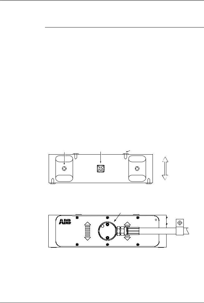
The load cell PFCL 201C is equipped with a connector for the pluggable connection cable. The load cell PFCL 201CE has a fi ed connection cable with protective hose.
The load cell PFCL 201CD is provided with an acid-proof cable gland with a fi ed PTFEinsulated connection cable.
Sensor |
Connector |
Mounting screw hole |
Measurement direction
 Mounting screw hole
Figure 3. Load Cell PFCL 201C
Fixed cable connector
Pressductor R |
Technology |
Figure 4. Load Cell PFCL 201CE with protective hose for cable
3BSE023881R0101 en Rev I |
9 |
Pressductor PillowBlock Load Cells, Vertical Measuring PFCL 201, User Manual
2 Description
Figure 5. Load Cell PFCL 201CD with insulated cable connection
2.2 |
Technical Data |
|
|
|
|
|
|
|
|
Table 1 Technical Data Load Cell PFCL 201 |
|
|
|
|
|
|
|
|
|
|
|
|
|
|
|
|
|
PFCL 201 |
Type |
Data |
|
|
|
Unit |
|
|
|
|
|
|
|
|
|
|
|
Nominal Loads 1) |
|
|
|
|
|
|
|
|
|
|
|
|
|
|
|
|
|
Nominal load in measuring direc- |
C/CD/CE |
5 |
10 |
20 |
50 |
kN |
|
|
tion, Fnom |
|
|
|
|
|
|
|
|
|
|
|
|
|
|
|
|
|
Permitted transverse force within |
|
2,5 |
5 |
10 |
25 |
|
|
|
the accuracy, FVnom (for h = 300 |
|
|
|
|
|
|
|
|
mm) |
|
|
|
|
|
|
|
|
|
|
|
|
|
|
|
|
|
Permitted axial load within the |
|
1,25 |
2,5 |
5 |
12.5 |
|
|
|
accuracy, FAnom (for h = 300 mm) |
|
|
|
|
|
|
|
|
|
|
|
|
|
|
|
|
|
Extended load in measuring direc- |
|
7,5 |
15 |
30 |
75 |
|
|
|
tion with accuracy class ±1%, Fext |
|
|
|
|
|
|
|
|
|
|
|
|
|
|
|
|
|
Max permitted load |
|
|
|
|
|
|
|
|
|
|
|
|
|
|
|
|
|
In the direction of measurement |
C/CD/CE |
50 |
100 |
200 |
5003) |
kN |
|
|
without permanent change of data, |
|
|
|
|
|
|
|
|
Fmax2) |
|
|
|
|
|
|
|
|
|
|
|
|
|
|
|
|
|
In the transverse direction without |
|
12,5 |
25 |
50 |
125 |
|
|
|
permanent change of data, FVmax2) |
|
|
|
|
|
|
|
|
(for h = 300 mm) |
|
|
|
|
|
|
|
|
|
|
|
|
|
|
|
|
|
Spring constant |
C/CD/CE |
250 |
500 |
1000 |
2500 |
kN/mm |
|
|
|
|
|
|
|
|
|
|
|
Mechanical data |
|
|
|
|
|
|
|
|
|
|
|
|
|
|
|
|
|
Length |
C/CD/CE |
450 |
|
|
|
mm |
|
|
|
|
|
|
|
|
|
|
|
Width |
C |
110 |
|
|
|
|
|
|
|
|
|
|
|
|
|
|
|
|
CD |
138 |
|
|
|
|
|
|
|
|
|
|
|
|
|
|
|
|
CE |
156 |
|
|
|
|
|
|
|
|
|
|
|
|
|
|
|
Height |
C/CD/CE |
124,6 |
|
|
|
|
|
|
|
|
|
|
|
|
|
|
|
Weight |
|
37 |
|
|
|
kg |
|
|
|
|
|
|
|
|
|
|
|
|
|
|
|
|
|
||
10 |
|
|
|
|
3BSE023881R0101 en Rev I |
|||
Pressductor PillowBlock Load Cells, Vertical Measuring PFCL 201, User Manual
2 Description
Material |
C/CD/CE |
Stainless steel SIS 2387 DIN X4CrNiMo 165 |
|
|
|
|
|
Accuracy |
|
|
|
|
|
|
|
Accuracy class |
C/CD/CE |
± 0,5 |
% |
|
|
|
|
Linearity deviation |
|
< ± 0,3 |
|
|
|
|
|
Repeatability error |
|
< ± 0,05 |
|
|
|
|
|
Hysteresis |
|
<0,2 |
|
|
|
|
|
Compensated temperature range |
|
+20 - +80 |
°C |
|
|
|
|
Zero point drift |
|
50 |
ppm/K |
|
|
|
|
Sensitivity drift |
|
100 |
|
|
|
|
|
Working temperature range |
|
-10 - +90 |
°C |
|
|
|
|
Zero point drift |
|
100 |
ppm/K |
|
|
|
|
Sensitivity drift |
|
200 |
|
|
|
|
|
Storage temperature range |
|
-40 - +90 |
°C |
|
|
|
|
1)efin t ons of directions designations “V”and “A” in FV and FA are given in Section 2.5.1 Coordinate System.
2)Fmax and FVmax are allowed at the same time.
3)Max. permitted load for the load cell is 10 × Fnom. The overload capacity for the total installation may be limited by
the screws.
h
Pressductor |
System |
h= Building Height
2.3 |
efin t ons |
Nominal load
Nominal load, Fnom, is the maximum load in the measurement direction for which the load cell is dimensioned to measure within the spec fied accuracy class. The load cell is calibrated up to Fnom.
Sensitivity
Sensitivity is defined as the difference in output values between nominal load and zero load.
3BSE023881R0101 en Rev I |
11 |
Loading...