


 Loading...
ABB industrial drives
Firmware manual
ACS880 primary control program

List of related manuals in English
Drive hardware manuals and guides |
Code (English) |
ACS880-01 hardware manual |
3AUA0000078093 |
ACS880-01 quick installation guide for frames R1 to R3 |
3AUA0000085966 |
ACS880-01 quick installation guide for frames R4 and R5 |
3AUA0000099663 |
ACS880-01 quick installation guide for frames R6 to R9 |
3AUA0000099689 |
Drive firmware manuals and guides |
|
ACS880 primary control program firmware manual |
3AUA0000085967 |
ACS880 drives with primary control program, quick start- |
3AUA0000098062 |
up guide |
|
Option manuals and guides |
|
ACS-AP-I and ACS-AP-S assistant control panel user’s |
3AUA0000085685 |
manual |
|
Drive composer Start-up and maintenance PC tool User’s |
3AUA0000094606 |
manual |
|
Manuals and quick guides for I/O extension modules, fieldbus adapters, encoder interfaces, etc.
You can find manuals and other product documents in PDF format on the Internet. See section Document library on the Internet on the inside of the back cover. For manuals not available in the Document library, contact your local ABB representative.
ACS880-01 manuals

Firmware manual
ACS880 primary control program
Table of contents
2012 ABB Oy. All Rights Reserved. |
3AUA0000085967 Rev C |
|
EN |
|
EFFECTIVE: 2012-04-01 |

Table of contents 5
Table of contents
List of related manuals in English . . . . . . . . . . . . . . . . . . . . . . . . . . . . . . . . . . . . . . . . . . . . . . . 2
1. Introduction to the manual |
|
What this chapter contains . . . . . . . . . . . . . . . . . . . . . . . . . . . . . . . . . . . . . . . . . . . . . . . . . . . |
11 |
Applicability . . . . . . . . . . . . . . . . . . . . . . . . . . . . . . . . . . . . . . . . . . . . . . . . . . . . . . . . . . . . . . . |
11 |
Safety instructions . . . . . . . . . . . . . . . . . . . . . . . . . . . . . . . . . . . . . . . . . . . . . . . . . . . . . . . . . . |
11 |
Target audience . . . . . . . . . . . . . . . . . . . . . . . . . . . . . . . . . . . . . . . . . . . . . . . . . . . . . . . . . . . . |
11 |
Contents of the manual . . . . . . . . . . . . . . . . . . . . . . . . . . . . . . . . . . . . . . . . . . . . . . . . . . . . . . |
12 |
Related documents . . . . . . . . . . . . . . . . . . . . . . . . . . . . . . . . . . . . . . . . . . . . . . . . . . . . . . . . . |
12 |
Terms and abbreviations . . . . . . . . . . . . . . . . . . . . . . . . . . . . . . . . . . . . . . . . . . . . . . . . . . . . . |
12 |
2.Using the control panel
3.Control locations and operating modes
What this chapter contains . . . . . . . . . . . . . . . . . . . . . . . . . . . . . . . . . . . . . . . . . . . . . . . . . . . |
17 |
Local control vs. external control . . . . . . . . . . . . . . . . . . . . . . . . . . . . . . . . . . . . . . . . . . . . . . . |
18 |
Local control . . . . . . . . . . . . . . . . . . . . . . . . . . . . . . . . . . . . . . . . . . . . . . . . . . . . . . . . . . . |
18 |
External control . . . . . . . . . . . . . . . . . . . . . . . . . . . . . . . . . . . . . . . . . . . . . . . . . . . . . . . . . |
19 |
Operating modes of the drive . . . . . . . . . . . . . . . . . . . . . . . . . . . . . . . . . . . . . . . . . . . . . . . . . |
20 |
Speed control mode . . . . . . . . . . . . . . . . . . . . . . . . . . . . . . . . . . . . . . . . . . . . . . . . . . . . . |
20 |
Torque control mode . . . . . . . . . . . . . . . . . . . . . . . . . . . . . . . . . . . . . . . . . . . . . . . . . . . . . |
21 |
Frequency control mode . . . . . . . . . . . . . . . . . . . . . . . . . . . . . . . . . . . . . . . . . . . . . . . . . . |
21 |
Special control modes . . . . . . . . . . . . . . . . . . . . . . . . . . . . . . . . . . . . . . . . . . . . . . . . . . . . |
21 |
4. Program features |
|
What this chapter contains . . . . . . . . . . . . . . . . . . . . . . . . . . . . . . . . . . . . . . . . . . . . . . . . . . . |
23 |
Drive configuration and programming . . . . . . . . . . . . . . . . . . . . . . . . . . . . . . . . . . . . . . . . . . . |
24 |
Programming via parameters . . . . . . . . . . . . . . . . . . . . . . . . . . . . . . . . . . . . . . . . . . . . . . |
24 |
Application programming . . . . . . . . . . . . . . . . . . . . . . . . . . . . . . . . . . . . . . . . . . . . . . . . . |
24 |
Control interfaces . . . . . . . . . . . . . . . . . . . . . . . . . . . . . . . . . . . . . . . . . . . . . . . . . . . . . . . . . . |
26 |
Programmable analog inputs . . . . . . . . . . . . . . . . . . . . . . . . . . . . . . . . . . . . . . . . . . . . . . |
26 |
Programmable analog outputs . . . . . . . . . . . . . . . . . . . . . . . . . . . . . . . . . . . . . . . . . . . . . |
26 |
Programmable digital inputs and outputs . . . . . . . . . . . . . . . . . . . . . . . . . . . . . . . . . . . . . |
26 |
Programmable relay outputs . . . . . . . . . . . . . . . . . . . . . . . . . . . . . . . . . . . . . . . . . . . . . . . |
26 |
Programmable I/O extensions . . . . . . . . . . . . . . . . . . . . . . . . . . . . . . . . . . . . . . . . . . . . . . |
27 |
Fieldbus control . . . . . . . . . . . . . . . . . . . . . . . . . . . . . . . . . . . . . . . . . . . . . . . . . . . . . . . . . |
27 |
Motor control . . . . . . . . . . . . . . . . . . . . . . . . . . . . . . . . . . . . . . . . . . . . . . . . . . . . . . . . . . . . . . |
28 |
Direct torque control (DTC) . . . . . . . . . . . . . . . . . . . . . . . . . . . . . . . . . . . . . . . . . . . . . . . . |
28 |
Reference ramping . . . . . . . . . . . . . . . . . . . . . . . . . . . . . . . . . . . . . . . . . . . . . . . . . . . . . . |
28 |
Constant speeds (frequencies) . . . . . . . . . . . . . . . . . . . . . . . . . . . . . . . . . . . . . . . . . . . . . |
29 |
Critical speeds (frequencies) . . . . . . . . . . . . . . . . . . . . . . . . . . . . . . . . . . . . . . . . . . . . . . . |
29 |
Encoder support . . . . . . . . . . . . . . . . . . . . . . . . . . . . . . . . . . . . . . . . . . . . . . . . . . . . . . . . |
30 |
Jogging . . . . . . . . . . . . . . . . . . . . . . . . . . . . . . . . . . . . . . . . . . . . . . . . . . . . . . . . . . . . . . . |
31 |
Scalar motor control . . . . . . . . . . . . . . . . . . . . . . . . . . . . . . . . . . . . . . . . . . . . . . . . . . . . . |
33 |

6 Table of contents
Autophasing . . . . . . . . . . . . . . . . . . . . . . . . . . . . . . . . . . . . . . . . . . . . . . . . . . . . . . . . . . . 34 Flux braking . . . . . . . . . . . . . . . . . . . . . . . . . . . . . . . . . . . . . . . . . . . . . . . . . . . . . . . . . . . 35 DC magnetization . . . . . . . . . . . . . . . . . . . . . . . . . . . . . . . . . . . . . . . . . . . . . . . . . . . . . . . 36 Application control . . . . . . . . . . . . . . . . . . . . . . . . . . . . . . . . . . . . . . . . . . . . . . . . . . . . . . . . . 38 Application macros . . . . . . . . . . . . . . . . . . . . . . . . . . . . . . . . . . . . . . . . . . . . . . . . . . . . . . 38 Process PID control . . . . . . . . . . . . . . . . . . . . . . . . . . . . . . . . . . . . . . . . . . . . . . . . . . . . . 38 Mechanical brake control . . . . . . . . . . . . . . . . . . . . . . . . . . . . . . . . . . . . . . . . . . . . . . . . . 41 DC voltage control . . . . . . . . . . . . . . . . . . . . . . . . . . . . . . . . . . . . . . . . . . . . . . . . . . . . . . . . . 46 Overvoltage control . . . . . . . . . . . . . . . . . . . . . . . . . . . . . . . . . . . . . . . . . . . . . . . . . . . . . 46 Undervoltage control . . . . . . . . . . . . . . . . . . . . . . . . . . . . . . . . . . . . . . . . . . . . . . . . . . . . 46 Voltage control and trip limits . . . . . . . . . . . . . . . . . . . . . . . . . . . . . . . . . . . . . . . . . . . . . . 47 Brake chopper . . . . . . . . . . . . . . . . . . . . . . . . . . . . . . . . . . . . . . . . . . . . . . . . . . . . . . . . . 48 Safety and protections . . . . . . . . . . . . . . . . . . . . . . . . . . . . . . . . . . . . . . . . . . . . . . . . . . . . . . 49 Emergency stop . . . . . . . . . . . . . . . . . . . . . . . . . . . . . . . . . . . . . . . . . . . . . . . . . . . . . . . . 49 Motor thermal protection . . . . . . . . . . . . . . . . . . . . . . . . . . . . . . . . . . . . . . . . . . . . . . . . . 49 Programmable protection functions . . . . . . . . . . . . . . . . . . . . . . . . . . . . . . . . . . . . . . . . . 52 Automatic fault resets . . . . . . . . . . . . . . . . . . . . . . . . . . . . . . . . . . . . . . . . . . . . . . . . . . . . 53 Diagnostics . . . . . . . . . . . . . . . . . . . . . . . . . . . . . . . . . . . . . . . . . . . . . . . . . . . . . . . . . . . . . . . 54 Signal supervision . . . . . . . . . . . . . . . . . . . . . . . . . . . . . . . . . . . . . . . . . . . . . . . . . . . . . . 54 Maintenance timers and counters . . . . . . . . . . . . . . . . . . . . . . . . . . . . . . . . . . . . . . . . . . 54 Energy savings calculator . . . . . . . . . . . . . . . . . . . . . . . . . . . . . . . . . . . . . . . . . . . . . . . . 54 Load analyzer . . . . . . . . . . . . . . . . . . . . . . . . . . . . . . . . . . . . . . . . . . . . . . . . . . . . . . . . . . 55 Miscellaneous . . . . . . . . . . . . . . . . . . . . . . . . . . . . . . . . . . . . . . . . . . . . . . . . . . . . . . . . . . . . . 56 Data storage parameters . . . . . . . . . . . . . . . . . . . . . . . . . . . . . . . . . . . . . . . . . . . . . . . . . 56
5. Application macros
What this chapter contains . . . . . . . . . . . . . . . . . . . . . . . . . . . . . . . . . . . . . . . . . . . . . . . . . . . 57 General . . . . . . . . . . . . . . . . . . . . . . . . . . . . . . . . . . . . . . . . . . . . . . . . . . . . . . . . . . . . . . . . . . 57 Factory macro . . . . . . . . . . . . . . . . . . . . . . . . . . . . . . . . . . . . . . . . . . . . . . . . . . . . . . . . . . . . 58 Default parameter settings for the Factory macro . . . . . . . . . . . . . . . . . . . . . . . . . . . . . . 58 Default control connections for the Factory macro . . . . . . . . . . . . . . . . . . . . . . . . . . . . . . 59 Hand/Auto macro . . . . . . . . . . . . . . . . . . . . . . . . . . . . . . . . . . . . . . . . . . . . . . . . . . . . . . . . . . 60 Default parameter settings for the Hand/Auto macro . . . . . . . . . . . . . . . . . . . . . . . . . . . . 60 Default control connections for the Hand/Auto macro . . . . . . . . . . . . . . . . . . . . . . . . . . . 61 PID control macro . . . . . . . . . . . . . . . . . . . . . . . . . . . . . . . . . . . . . . . . . . . . . . . . . . . . . . . . . . 62 Default parameter settings for the PID control macro . . . . . . . . . . . . . . . . . . . . . . . . . . . 63 Default control connections for the PID control macro . . . . . . . . . . . . . . . . . . . . . . . . . . . 64 Sensor connection examples . . . . . . . . . . . . . . . . . . . . . . . . . . . . . . . . . . . . . . . . . . . . . . 65 Torque control macro . . . . . . . . . . . . . . . . . . . . . . . . . . . . . . . . . . . . . . . . . . . . . . . . . . . . . . . 66 Default parameter settings for the Torque control macro . . . . . . . . . . . . . . . . . . . . . . . . . 66 Default control connections for the Torque control macro . . . . . . . . . . . . . . . . . . . . . . . . 67 Sequential control macro . . . . . . . . . . . . . . . . . . . . . . . . . . . . . . . . . . . . . . . . . . . . . . . . . . . . 68 Operation diagram . . . . . . . . . . . . . . . . . . . . . . . . . . . . . . . . . . . . . . . . . . . . . . . . . . . . . . 68 Selection of constant speeds . . . . . . . . . . . . . . . . . . . . . . . . . . . . . . . . . . . . . . . . . . . . . . 69 Default parameter settings for the Sequential control macro . . . . . . . . . . . . . . . . . . . . . . 69 Default control connections for the Sequential control macro . . . . . . . . . . . . . . . . . . . . . 70 Fieldbus control macro . . . . . . . . . . . . . . . . . . . . . . . . . . . . . . . . . . . . . . . . . . . . . . . . . . . . . . 71

|
|
Table of contents 7 |
6. Parameters |
|
|
What this chapter contains . . . . . . . . . . . . . . . . . . . . . . . . . . . . . . . . . . . |
. . . . . . . . . . . . . . . . 73 |
|
Terms and abbreviations . . . . . . . . . . . . . . . . . . . . . . . . . . . . . . . . . . . . . |
. . . . . . . . . . . . . . . . 73 |
|
Summary of parameter groups . . . . . . . . . . . . . . . . . . . . . . . . . . . . . . . . |
. . . . . . . . . . . . . . . . 74 |
|
Parameter listing . . . . . . . . . . . . . . . . . . . . . . . . . . . . . . . . . . . . . . . . . . . . |
. . . . . . . . . . . . . . . 76 |
|
01 |
Actual values . . . . . . . . . . . . . . . . . . . . . . . . . . . . . . . . . . . . . . . . . |
. . . . . . . . . . . . . . . 76 |
03 |
Input references . . . . . . . . . . . . . . . . . . . . . . . . . . . . . . . . . . . . . . . |
. . . . . . . . . . . . . . . 77 |
04 |
Warnings and faults . . . . . . . . . . . . . . . . . . . . . . . . . . . . . . . . . . . . |
. . . . . . . . . . . . . . . 77 |
05 |
Diagnostics . . . . . . . . . . . . . . . . . . . . . . . . . . . . . . . . . . . . . . . . . . . |
. . . . . . . . . . . . . . . 78 |
06 |
Control and status words . . . . . . . . . . . . . . . . . . . . . . . . . . . . . . . . |
. . . . . . . . . . . . . . . 79 |
07 |
System info . . . . . . . . . . . . . . . . . . . . . . . . . . . . . . . . . . . . . . . . . . |
. . . . . . . . . . . . . . . 82 |
10 |
Standard DI, RO . . . . . . . . . . . . . . . . . . . . . . . . . . . . . . . . . . . . . . . |
. . . . . . . . . . . . . . . 83 |
11 |
Standard DIO, FI, FO . . . . . . . . . . . . . . . . . . . . . . . . . . . . . . . . . . . |
. . . . . . . . . . . . . . . 88 |
12 |
Standard AI . . . . . . . . . . . . . . . . . . . . . . . . . . . . . . . . . . . . . . . . . . |
. . . . . . . . . . . . . . . 93 |
13 Standard AO . . . . . . . . . . . . . . . . . . . . . . . . . . . . . . . . . . . . . . . . . |
. . . . . . . . . . . . . . . 95 |
|
19 |
Operation mode . . . . . . . . . . . . . . . . . . . . . . . . . . . . . . . . . . . . . . . |
. . . . . . . . . . . . . . . 99 |
20 |
Start/stop/direction . . . . . . . . . . . . . . . . . . . . . . . . . . . . . . . . . . . . . |
. . . . . . . . . . . . . . 100 |
21 |
Start/stop mode . . . . . . . . . . . . . . . . . . . . . . . . . . . . . . . . . . . . . . . |
. . . . . . . . . . . . . . 108 |
22 |
Speed reference selection . . . . . . . . . . . . . . . . . . . . . . . . . . . . . . . |
. . . . . . . . . . . . . . 113 |
23 |
Speed reference ramp . . . . . . . . . . . . . . . . . . . . . . . . . . . . . . . . . . |
. . . . . . . . . . . . . . 119 |
24 |
Speed reference conditioning . . . . . . . . . . . . . . . . . . . . . . . . . . . . |
. . . . . . . . . . . . . . 123 |
25 |
Speed control . . . . . . . . . . . . . . . . . . . . . . . . . . . . . . . . . . . . . . . . . |
. . . . . . . . . . . . . . 126 |
26 |
Torque reference chain . . . . . . . . . . . . . . . . . . . . . . . . . . . . . . . . . |
. . . . . . . . . . . . . . 131 |
28 |
Frequency reference chain . . . . . . . . . . . . . . . . . . . . . . . . . . . . . . |
. . . . . . . . . . . . . . 135 |
30 |
Limits . . . . . . . . . . . . . . . . . . . . . . . . . . . . . . . . . . . . . . . . . . . . . . . |
. . . . . . . . . . . . . . 143 |
31 |
Fault functions . . . . . . . . . . . . . . . . . . . . . . . . . . . . . . . . . . . . . . . . |
. . . . . . . . . . . . . . 145 |
32 |
Supervision . . . . . . . . . . . . . . . . . . . . . . . . . . . . . . . . . . . . . . . . . . |
. . . . . . . . . . . . . . 150 |
33 |
Maintenance timer & counter . . . . . . . . . . . . . . . . . . . . . . . . . . . . . |
. . . . . . . . . . . . . . 153 |
35 |
Motor thermal protection . . . . . . . . . . . . . . . . . . . . . . . . . . . . . . . . |
. . . . . . . . . . . . . . 159 |
36 |
Load analyzer . . . . . . . . . . . . . . . . . . . . . . . . . . . . . . . . . . . . . . . . . |
. . . . . . . . . . . . . . 166 |
40 |
Process PID set 1 . . . . . . . . . . . . . . . . . . . . . . . . . . . . . . . . . . . . . |
. . . . . . . . . . . . . . 169 |
41 |
Process PID set 2 . . . . . . . . . . . . . . . . . . . . . . . . . . . . . . . . . . . . . |
. . . . . . . . . . . . . . 180 |
43 |
Brake chopper . . . . . . . . . . . . . . . . . . . . . . . . . . . . . . . . . . . . . . . . |
. . . . . . . . . . . . . . 181 |
44 |
Mechanical brake control . . . . . . . . . . . . . . . . . . . . . . . . . . . . . . . . |
. . . . . . . . . . . . . . 183 |
45 |
Energy efficiency . . . . . . . . . . . . . . . . . . . . . . . . . . . . . . . . . . . . . . |
. . . . . . . . . . . . . . 187 |
46 |
Monitoring/scaling settings . . . . . . . . . . . . . . . . . . . . . . . . . . . . . . . |
. . . . . . . . . . . . . . 189 |
47 |
Data storage . . . . . . . . . . . . . . . . . . . . . . . . . . . . . . . . . . . . . . . . . . |
. . . . . . . . . . . . . . 191 |
49 |
Panel port communication . . . . . . . . . . . . . . . . . . . . . . . . . . . . . . . |
. . . . . . . . . . . . . . 193 |
50 |
Fieldbus adapter (FBA) . . . . . . . . . . . . . . . . . . . . . . . . . . . . . . . . . |
. . . . . . . . . . . . . . 193 |
51 |
FBA A settings . . . . . . . . . . . . . . . . . . . . . . . . . . . . . . . . . . . . . . . . |
. . . . . . . . . . . . . . 197 |
52 |
FBA A data in . . . . . . . . . . . . . . . . . . . . . . . . . . . . . . . . . . . . . . . . . |
. . . . . . . . . . . . . . 198 |
53 |
FBA A data out . . . . . . . . . . . . . . . . . . . . . . . . . . . . . . . . . . . . . . . . |
. . . . . . . . . . . . . . 199 |
90 |
Feedback selection . . . . . . . . . . . . . . . . . . . . . . . . . . . . . . . . . . . . |
. . . . . . . . . . . . . . 199 |
91 |
Encoder module settings . . . . . . . . . . . . . . . . . . . . . . . . . . . . . . . . |
. . . . . . . . . . . . . . 204 |
92 |
Encoder 1 configuration . . . . . . . . . . . . . . . . . . . . . . . . . . . . . . . . . |
. . . . . . . . . . . . . . 206 |
93 |
Encoder 2 configuration . . . . . . . . . . . . . . . . . . . . . . . . . . . . . . . . . |
. . . . . . . . . . . . . . 211 |
95 |
HW configuration . . . . . . . . . . . . . . . . . . . . . . . . . . . . . . . . . . . . . . |
. . . . . . . . . . . . . . 213 |
96 System . . . . . . . . . . . . . . . . . . . . . . . . . . . . . . . . . . . . . . . . . . . . . . |
. . . . . . . . . . . . . . 215 |
|
97 |
Motor control . . . . . . . . . . . . . . . . . . . . . . . . . . . . . . . . . . . . . . . . . |
. . . . . . . . . . . . . . 216 |
98 |
User motor parameters . . . . . . . . . . . . . . . . . . . . . . . . . . . . . . . . . |
. . . . . . . . . . . . . . 218 |

8 Table of contents
99 Motor data . . . . . . . . . . . . . . . . . . . . . . . . . . . . . . . . . . . . . . . . . . . . . . . . . . . . . . . . . |
220 |
7. Additional parameter data
What this chapter contains . . . . . . . . . . . . . . . . . . . . . . . . . . . . . . . . . . . . . . . . . . . . . . . . . . 225 Terms and abbreviations . . . . . . . . . . . . . . . . . . . . . . . . . . . . . . . . . . . . . . . . . . . . . . . . . . . 225 Fieldbus addresses . . . . . . . . . . . . . . . . . . . . . . . . . . . . . . . . . . . . . . . . . . . . . . . . . . . . . . . 226 Parameter groups 1…9 . . . . . . . . . . . . . . . . . . . . . . . . . . . . . . . . . . . . . . . . . . . . . . . . . . . . 227 Parameter groups 10…99 . . . . . . . . . . . . . . . . . . . . . . . . . . . . . . . . . . . . . . . . . . . . . . . . . . 229
8. Fault tracing
What this chapter contains . . . . . . . . . . . . . . . . . . . . . . . . . . . . . . . . . . . . . . . . . . . . . . . . . . 253 Safety . . . . . . . . . . . . . . . . . . . . . . . . . . . . . . . . . . . . . . . . . . . . . . . . . . . . . . . . . . . . . . . . . . 253 How to reset . . . . . . . . . . . . . . . . . . . . . . . . . . . . . . . . . . . . . . . . . . . . . . . . . . . . . . . . . . . . . 253 Warning/fault history . . . . . . . . . . . . . . . . . . . . . . . . . . . . . . . . . . . . . . . . . . . . . . . . . . . . . . . 254 Event log . . . . . . . . . . . . . . . . . . . . . . . . . . . . . . . . . . . . . . . . . . . . . . . . . . . . . . . . . . . . 254 Parameters that contain warning/fault information . . . . . . . . . . . . . . . . . . . . . . . . . . . . . 254 Warning messages . . . . . . . . . . . . . . . . . . . . . . . . . . . . . . . . . . . . . . . . . . . . . . . . . . . . . . . . 255 Fault messages . . . . . . . . . . . . . . . . . . . . . . . . . . . . . . . . . . . . . . . . . . . . . . . . . . . . . . . . . . 262
9.Fieldbus control through the embedded fieldbus interface (EFB)
10.Fieldbus control through a fieldbus adapter
What this chapter contains . . . . . . . . . . . . . . . . . . . . . . . . . . . . . . . . . . . . . . . . . . . . . . . . . . 273 System overview . . . . . . . . . . . . . . . . . . . . . . . . . . . . . . . . . . . . . . . . . . . . . . . . . . . . . . . . . 274 Basics of the fieldbus control interface . . . . . . . . . . . . . . . . . . . . . . . . . . . . . . . . . . . . . . . . . 275 Control word and Status word . . . . . . . . . . . . . . . . . . . . . . . . . . . . . . . . . . . . . . . . . . . . 276 References . . . . . . . . . . . . . . . . . . . . . . . . . . . . . . . . . . . . . . . . . . . . . . . . . . . . . . . . . . . 277 Actual values . . . . . . . . . . . . . . . . . . . . . . . . . . . . . . . . . . . . . . . . . . . . . . . . . . . . . . . . . 278 Contents of the fieldbus Control word . . . . . . . . . . . . . . . . . . . . . . . . . . . . . . . . . . . . . . 279 Contents of the fieldbus Status word . . . . . . . . . . . . . . . . . . . . . . . . . . . . . . . . . . . . . . . 280 The state diagram . . . . . . . . . . . . . . . . . . . . . . . . . . . . . . . . . . . . . . . . . . . . . . . . . . . . . 281 Setting up the drive for fieldbus control . . . . . . . . . . . . . . . . . . . . . . . . . . . . . . . . . . . . . . . . 282 Parameter setting example: FPBA (PROFIBUS DP) . . . . . . . . . . . . . . . . . . . . . . . . . . . 283
11.Drive-to-drive link
12.Control chain diagrams
What this chapter contains . . . . . . . . . . . . . . . . . . . . . . . . . . . . . . . . . . . . . . . . . . . . . . . . . . 287 Speed reference source selection I . . . . . . . . . . . . . . . . . . . . . . . . . . . . . . . . . . . . . . . . . . . 288 Speed reference source selection II . . . . . . . . . . . . . . . . . . . . . . . . . . . . . . . . . . . . . . . . . . . 289 Speed reference ramping and shaping . . . . . . . . . . . . . . . . . . . . . . . . . . . . . . . . . . . . . . . . 290 Motor feedback configuration . . . . . . . . . . . . . . . . . . . . . . . . . . . . . . . . . . . . . . . . . . . . . . . . 291 Speed error calculation . . . . . . . . . . . . . . . . . . . . . . . . . . . . . . . . . . . . . . . . . . . . . . . . . . . . 292 Speed controller . . . . . . . . . . . . . . . . . . . . . . . . . . . . . . . . . . . . . . . . . . . . . . . . . . . . . . . . . . 293 Torque reference source selection and modification . . . . . . . . . . . . . . . . . . . . . . . . . . . . . . 294 Reference selection for torque controller I . . . . . . . . . . . . . . . . . . . . . . . . . . . . . . . . . . . . . . 295 Reference selection for torque controller II . . . . . . . . . . . . . . . . . . . . . . . . . . . . . . . . . . . . . 296

Table of contents 9
Torque limitation . . . . . . . . . . . . . . . . . . . . . . . . . . . . . . . . . . . . . . . . . . . . . . . . . . . . . . . . . . 297 Frequency reference selection . . . . . . . . . . . . . . . . . . . . . . . . . . . . . . . . . . . . . . . . . . . . . . . 298 Frequency reference modification . . . . . . . . . . . . . . . . . . . . . . . . . . . . . . . . . . . . . . . . . . . . . 299 Process PID setpoint and feedback source selection . . . . . . . . . . . . . . . . . . . . . . . . . . . . . . 300 Process PID controller . . . . . . . . . . . . . . . . . . . . . . . . . . . . . . . . . . . . . . . . . . . . . . . . . . . . . . 301
Further information |
|
Product and service inquiries . . . . . . . . . . . . . . . . . . . . . . . . . . . . . . . . . . . . . . . . . . . . . . . . |
303 |
Product training . . . . . . . . . . . . . . . . . . . . . . . . . . . . . . . . . . . . . . . . . . . . . . . . . . . . . . . . . . . |
303 |
Providing feedback on ABB Drives manuals . . . . . . . . . . . . . . . . . . . . . . . . . . . . . . . . . . . . . |
303 |
Document library on the Internet . . . . . . . . . . . . . . . . . . . . . . . . . . . . . . . . . . . . . . . . . . . . . . |
303 |

10 Table of contents
Introduction to the manual 11
1
Introduction to the manual
What this chapter contains
This chapter describes the contents of the manual. It also contains information on the compatibility, safety and intended audience.
Applicability
This manual applies to the ACS880 primary control program (version 1.10 or later).
The firmware version of the control program is visible in parameter 07.05 Firmware version.
Safety instructions
Follow all safety instructions delivered with the drive.
•Read the complete safety instructions before you install, commission, or use the drive. The complete safety instructions are delivered with the drive as either part of the Hardware manual, or, in the case of ACS880 multidrives, as a separate document.
•Read the firmware function-specific warnings and notes before changing parameter values. These warnings and notes are included in the parameter descriptions presented in chapter Parameters.
Target audience
This manual is intended for people who design, commission, or operate the drive system.

12 Introduction to the manual
Contents of the manual
This manual consists of the following chapters:
•Using the control panel provides the basic instructions for use of the control panel.
•Control locations and operating modes describes the control locations and operating modes of the drive.
•Program features contains descriptions of the features of the ACS880 primary control program.
•Application macros contains a short description of each macro together with a connection diagram.
•Parameters describes the parameters of the drive.
•Additional parameter data contains further information on the parameters.
•Fault tracing lists the warning and fault messages with possible causes and remedies.
•Fieldbus control through the embedded fieldbus interface (EFB) describes the communication to and from a fieldbus network using the embedded fieldbus interface of the drive.
•Fieldbus control through a fieldbus adapter describes the communication to and from a fieldbus network using an optional fieldbus adapter module.
•Drive-to-drive link describes the communication between drives connected together by the drive-to-drive (D2D) link.
•Control chain diagrams.
Related documents
Note: A quick start-up sequence for a speed control application is provided by
ACS880 drives with primary control program, Quick start-up guide
(3AUA0000098062), delivered with the drive.
A list of related manuals is printed on the inside of the front cover.
Terms and abbreviations
Term/abbreviation |
Definition |
|
|
ACS-AP-I |
Type of control panel used with ACS880 drives |
|
|
AI |
Analog input; interface for analog input signals |
|
|
AO |
Analog output; interface for analog output signals |
|
|
BCU |
Type of control unit used in ACS880 drives. |
|
|
DC link |
DC circuit between rectifier and inverter |
|
|
DDCS |
Distributed drives communication system; a protocol used in |
|
optical fiber communication |
|
|
|
|

|
Introduction to the manual 13 |
|
|
Term/abbreviation |
Definition |
|
|
DI |
Digital input; interface for digital input signals |
|
|
DIO |
Digital input/output; interface that can be used as a digital input |
|
or output |
|
|
DO |
Digital output; interface for digital output signals |
|
|
DTC |
Direct torque control |
|
|
EFB |
Embedded fieldbus |
|
|
FBA |
Fieldbus adapter |
|
|
FEN-01 |
Optional TTL encoder interface module |
|
|
FEN-11 |
Optional absolute encoder interface module |
|
|
FEN-21 |
Optional resolver interface module |
|
|
FEN-31 |
Optional HTL encoder interface module |
|
|
FIO-01 |
Optional digital I/O extension module |
|
|
FIO-11 |
Optional analog I/O extension module |
|
|
FCAN-0x |
Optional CANopen adapter |
|
|
FDNA-0x |
Optional DeviceNet adapter |
|
|
FECA-01 |
Optional EtherCAT® adapter |
|
|
FENA-11 |
Optional Ethernet/IP adapter |
|
|
FLON-0x |
Optional LONWORKS® adapter |
FPBA-0x |
Optional PROFIBUS DP adapter |
|
|
FSCA-0x |
Optional Modbus adapter |
|
|
HTL |
High-threshold logic |
|
|
IGBT |
Insulated gate bipolar transistor; a voltage-controlled |
|
semiconductor type widely used in inverters due to their easy |
|
controllability and high switching frequency |
|
|
I/O |
Input/Output |
|
|
ID run |
Motor identification run. During the identification run, the drive |
|
will identify the characteristics of the motor for optimum motor |
|
control. |
|
|
LSB |
Least significant bit |
|
|
LSW |
Least significant word |
|
|
MSB |
Most significant bit |
|
|
MSW |
Most significant word |
|
|

14 Introduction to the manual
Term/abbreviation |
Definition |
|
|
Network control |
With fieldbus protocols based on the Common Industrial |
|
Protocol (CIPTM), such as DeviceNet and Ethernet/IP, denotes |
|
the control of the drive using the Net Ctrl and Net Ref objects of |
|
the ODVA AC/DC Drive Profile. For more information, see |
|
www.odva.org, and the following manuals: |
|
• FDNA-01 DeviceNet adapter module User’s manual |
|
(3AFE68573360 [English]), and |
|
• FENA-01/-11 Ethernet adapter module User’s manual |
|
(3AUA0000093568 [English]). |
|
|
Parameter |
User-adjustable operation instruction to the drive, or signal |
|
measured or calculated by the drive |
|
|
PID controller |
Proportional–integral–derivative controller. Drive speed control |
|
is based on PID algorithm. |
|
|
PLC |
Programmable logic controller |
|
|
Power unit |
Contains the power electronics and connections of the drive. |
|
The drive control unit is connected to the power unit. |
|
|
PTC |
Positive temperature coefficient |
|
|
RFG |
Ramp function generator. |
|
|
RO |
Relay output; interface for a digital output signal. Implemented |
|
with a relay. |
|
|
SSI |
Synchronous serial interface |
|
|
STO |
Safe torque off |
|
|
TTL |
Transistor-transistor logic |
|
|
UPS |
Uninterruptible power supply; power supply equipment with |
|
battery to maintain output voltage during power failure |
|
|
ZCON |
Type of control board used in ACS880 drives. The board is |
|
either integrated into the drive or fitted in a plastic housing (see |
|
ZCU). |
|
|
ZCU |
Type of control unit used in ACS880 drives that consists of a |
|
ZCON board built into a plastic housing. |
|
The control unit may be fitted onto the drive/inverter module, or |
|
installed separately. |
|
|

Using the control panel 15
2
Using the control panel
Refer to ACS-AP-I and ACS-AP-S assistant control panels user’s manual
(3AUA0000085685 [English]).

16 Using the control panel

Control locations and operating modes 17
3
Control locations and operating modes
What this chapter contains
This chapter describes the control locations and operating modes supported by the control program.
18 Control locations and operating modes
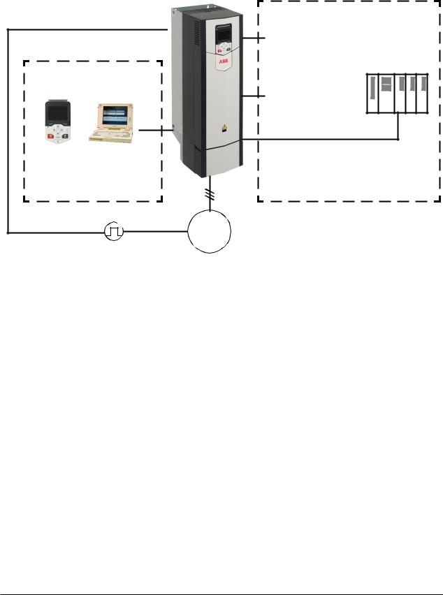
Local control vs. external control
The ACS880 has two main control locations: external and local. The control location is selected with the Loc/Rem key on the control panel or in the PC tool.
ACS880 |
2) |
Local control |
Control panel or Drive composer |
PC tool (optional) |
M |
3~ |
Encoder |
External control
I/O 1)
Drive-to-drive (D2D) link or Embedded fieldbus interface
PLC
(= Programmable logic controller)
Fieldbus adapter or DDCS communication module Fxxx
1)Extra inputs/outputs can be added by installing optional I/O extension modules (FIO-xx) in drive slots.
2)Encoder or resolver interface module(s) (FEN-xx) installed in drive slots.
Local control
The control commands are given from the control panel keypad or from a PC equipped with Drive composer when the drive is in local control. Speed and torque control modes are available for local control; frequency mode is available when scalar motor control mode is used (see parameter 19.16 Local control mode).
Local control is mainly used during commissioning and maintenance. The control panel always overrides the external control signal sources when used in local control. Changing the control location to local can be prevented by parameter 19.17 Local control disable.
The user can select by a parameter (49.05 Communication loss action) how the drive reacts to a control panel or PC tool communication break. (The parameter has no effect in external control.)

Control locations and operating modes 19
External control
When the drive is in external control, control commands are given through the fieldbus interface (via or an optional fieldbus adapter module), the I/O terminals (digital and analog inputs), or optional I/O extension modules.
Two external control locations, EXT1 and EXT2, are available. The user can select the sources of the start and stop commands separately for each location by parameters 20.01…20.10. The operating mode can be selected separately for each location, which enables quick switching between different operating modes, for example speed and torque control. Selection between EXT1 and EXT2 is done via any binary source such as a digital input or fieldbus control word (see parameter 19.11 Ext1/Ext2 selection). The source of reference is selectable for each operating mode separately.

20 Control locations and operating modes
Operating modes of the drive
The drive can operate in several operating modes with different types of reference. The mode is selectable for each control location (Local, EXT1 and EXT2) in parameter group 19 Operation mode.
The following is a general representation of the reference types and control chains. The page numbers refer to detailed diagrams in chapter Control chain diagrams.
|
|
Speed |
|
|
Speed reference |
|
|
Speed reference |
|
Speed error |
|
Motor feedback |
|
|
|
reference |
|
|
source selection |
|
|
ramping and |
|
calculation |
|
configuration |
|
|
|
source selection |
|
|
II |
|
|
shaping |
|
(page 292) |
|
(page 291) |
|
|
|
I |
|
|
(page 289) |
|
|
(page 290) |
|
|
|
|
|
|
|
(page 288) |
|
|
|
|
|
|
|
|
|
|
|
|
|
|
|
|
|
|
|
|
|
|
|
|
|
|
|
|
|
|
|
|
|
|
|
|
|
|
|
|
|
Torque |
|
|
|
|
|
|
|
|
Speed controller |
|
|
|
|
reference |
|
|
|
|
|
|
|
|
(page 293) |
|
|
|
|
source selection |
|
|
|
|
|
|
|
|
|
|
|
|
|
and modification |
|
|
|
|
|
|
|
|
|
|
|
|
|
(page 294) |
|
|
|
|
|
|
|
|
|
|
|
|
|
|
|
|
|
|
|
|
|
|
|
|
|
|
|
|
|
|
|
|
|
|
|
|
|
|
|
|
|
|
|
|
|
|
|
|
|
|
Reference |
|
|
|
|
|
|
|
|
|
|
|
|
|
|
||
|
|
|
|
|
|
|
|
|
|
|
selection for |
|
|
|
|
Process PID |
|
|
|
|
|
|
|
|
|
||
|
|
|
|
|
|
|
|
|
|
torque controller |
|
||
|
|
setpoint and |
|
|
|
|
|
|
|
|
(page 295) |
|
|
|
|
|
|
|
|
|
|
|
|
|
|||
|
|
feedback source |
|
|
|
|
|
|
|
|
|
||
|
|
|
|
|
|
|
|
|
|
|
|
|
|
|
|
selection |
|
|
|
|
|
|
|
|
|
|
|
(page 300) |
|
Torque |
|
|
Reference |
controller |
|
|
|
||
|
modification for |
|
|
Process PID |
torque controller |
|
|
(page 296) |
|
||
controller |
DTC motor |
||
|
|||
(page 301) |
|
control mode |
|
|
|
Scalar motor |
|
|
|
control mode |
Frequency reference source selection and modification
(page 298)
Speed control mode
The motor follows a speed reference given to the drive. This mode can be used either with estimated speed used as feedback, or with an encoder or resolver for better speed control accuracy.
Control locations and operating modes 21
Speed control mode is available in both local and external control. It is also available both in DTC (Direct Torque Control) and scalar motor control modes.
Torque control mode
Motor torque follows a torque reference given to the drive. This mode can be used either with or without an encoder or resolver. When used with an encoder or resolver, this mode provides for more accurate and dynamic motor control.
Torque control mode is available in both local and external control.
Frequency control mode
The motor follows a frequency reference given to the drive. Frequency control is only available for scalar motor control.
Special control modes
In addition to the above-mentioned control modes, the following special control modes are available:
•Process PID control. For more information, see section Process PID control (page
38).
•Emergency stop modes OFF1 and OFF3: Drive stops along the defined deceleration ramp and drive modulation stops.
•Jogging mode: Drive starts and accelerates to the defined speed when the jogging signal is activated. For more information, see section Jogging (page 31).

22 Control locations and operating modes

Program features 23
4
Program features
What this chapter contains
This chapter describes the features of the control program.
24 Program features
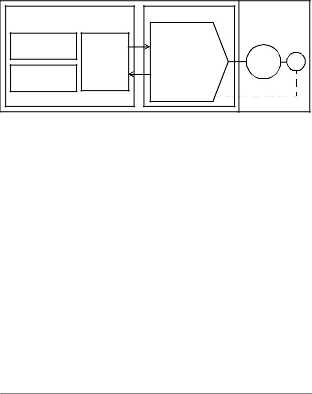
Drive configuration and programming
The drive control program is divided into two parts:
•firmware program
•application program.
Drive control program
Application program |
Firmware |
|
|
||
|
|
Speed control |
|
|
|
Function block |
|
Torque control |
|
|
|
|
Frequency control |
|
|
||
program |
Parameter |
M |
|
||
Drive logic |
E |
||||
|
|||||
Standard |
interface |
I/O interface |
|||
|
Fieldbus interface |
|
|
||
block library |
|
|
|
||
|
Protections |
|
|
||
|
|
|
|
||
|
|
Feedback |
|
|
|
The firmware program performs the main control functions, including speed and torque control, drive logic (start/stop), I/O, feedback, communication and protection functions. Firmware functions are configured and programmed with parameters.
Programming via parameters
Parameters can be set via
•the control panel, as described in chapter Using the control panel
•the Drive composer PC tool, as described in Drive composer user’s manual (3AUA0000094606 [English]), or
•the fieldbus interface, as described in chapters Fieldbus control through the embedded fieldbus interface (EFB) and Fieldbus control through a fieldbus adapter.
All parameter settings are stored automatically to the permanent memory of the drive. However, if an external +24 V DC power supply is used for the drive control unit, it is highly recommended to force a save by using parameter 96.07 Parameter save before powering down the control unit after any parameter changes.
If necessary, the default parameter values can be restored by parameter 96.06 Parameter restore.
Application programming
The functions of the firmware program can be extended with application programming. (A standard drive delivery does not include an application program.)

Program features 25
Application programs can be built out of function blocks based on the IEC-61131 standard.

26 Program features
Control interfaces
Programmable analog inputs
The drive control unit has two programmable analog inputs. Each of the inputs can be independently set as a voltage (0/2…10 V or -10…10 V) or current (0/4…20 mA) input by a jumper on the drive control unit. Each input can be filtered, inverted and scaled. The number of analog inputs can be increased by using FIO-xx I/O extensions.
Settings
Parameter group 12 Standard AI (page 93).
Programmable analog outputs
The drive control unit has two current (0…20 mA) analog outputs. Each output can be filtered, inverted and scaled. The number of analog outputs can be increased by using FIO-xx I/O extensions.
Settings
Parameter group 13 Standard AO (page 95).
Programmable digital inputs and outputs
The drive has six digital inputs, a digital start interlock input, and two digital input/outputs.
One digital input (DI6) doubles as a PTC thermistor input. See section Motor thermal protection (page 49).
Digital input/output DIO1 can be used as a frequency input, DIO2 as a frequency output.
The number of digital inputs/outputs can be increased by using FIO-xx I/O extensions.
Settings
Parameter groups 10 Standard DI, RO (page 83) and 11 Standard DIO, FI, FO (page 88).
Programmable relay outputs
The drive control unit has three relay outputs. The signal to be indicated by the outputs can be selected by parameters.
Relay outputs can be added by using FIO-0x I/O extensions.

Program features 27
Settings
Parameter group 10 Standard DI, RO (page 83).
Programmable I/O extensions
The number of inputs and outputs can be increased by using FIO-xx I/O extensions. The I/O configuration parameters (parameter groups 10…13) include the maximum number of DI, DIO, AI, AO and RO that can be in use with different FIO-xx combinations.
The table below shows the possible I/O combinations:
|
Digital |
Digital I/Os |
Analog |
Analog |
Relay |
Location |
inputs |
|
inputs |
outputs |
outputs |
|
(DI) |
(DIO) |
(AI) |
(AO) |
(RO) |
|
|
|
|
|
|
Drive control unit |
7 |
2 |
2 |
2 |
3 |
|
|
|
|
|
|
FIO-01 |
- |
4 |
- |
- |
2 |
|
|
|
|
|
|
FIO-11 |
- |
2 |
3 |
1 |
- |
|
|
|
|
|
|
For example, with an FIO-01 and an FIO-11 connected to the drive, parameters controlling DI1…7, DIO1…8, AI1…5, AO1…3 and RO1…5 are in use.
Settings
Parameter groups 10 Standard DI, RO (page 83), 11 Standard DIO, FI, FO (page 88), 12 Standard AI (page 93) and 13 Standard AO (page 95).
Fieldbus control
The drive can be connected to several different automation systems through its fieldbus interfaces. See chapter Fieldbus control through a fieldbus adapter (page 273)
Settings
Parameter groups 50 Fieldbus adapter (FBA) (page 193), 51 FBA A settings (page 197), 52 FBA A data in (page 198), and 53 FBA A data out (page 199).

28 Program features
Motor control
Direct torque control (DTC)
The motor control of the ACS880 is based on direct torque control (DTC). The switching of the output semiconductors is controlled to achieve the required stator flux and motor torque. The switching frequency is changed only if the actual torque and stator flux values differ from their reference values by more than the allowed hysteresis. The reference value for the torque controller comes from the speed controller or directly from an external torque reference source.
Motor control requires measurement of the DC voltage and two motor phase currents. Stator flux is calculated by integrating the motor voltage in vector space. Motor torque is calculated as a cross product of the stator flux and the rotor current. By utilizing the identified motor model, the stator flux estimate is improved. Actual motor shaft speed is not needed for the motor control.
The main difference between traditional control and DTC is that torque control has the same time level as the power switch control. There is no separate voltage and frequency controlled PWM modulator; the output stage switching is wholly based on the electromagnetic state of the motor.
The best motor control accuracy is achieved by activating a separate motor identification run (ID run).
See also section Scalar motor control (page 33).
Settings
Parameters 99.04 Motor ctrl mode (page 220) and 99.13 Identification run request
(page 222).
Reference ramping
Acceleration and deceleration ramping times can be set individually for speed, torque and frequency reference.
With a speed or frequency reference, the ramps are defined as the time it takes for the drive to accelerate or decelerate between zero speed or frequency and the value defined by parameter 46.01 Speed scaling or 46.02 Frequency scaling. The user can switch between two preset ramp sets using a binary source such as a digital input. For speed reference, also the shape of the ramp can be controlled.
With a torque reference, the ramps are defined as the time it takes for the reference to change between zero and nominal motor torque (parameter 01.30 Nominal torque scale).

Program features 29
Special acceleration/deceleration ramps
The acceleration/deceleration times for the jogging function can be defined separately; see section Jogging (page 31). Furthermore, a deceleration ramp can be defined for emergency stop (“Off3” mode).
Settings
•Speed reference ramping: Parameters 23.11…23.19 and 46.01 (pages 119 and 189).
•Torque reference ramping: Parameters 01.30, 26.18 and 26.19 (pages 77 and 133).
•Frequency reference ramping: Parameters 28.71…28.75 and 46.02 (pages 139 and 189).
•Jogging: Parameters 23.20 and 23.21 (page 122).
•Emergency stop (“Off3” mode): Parameter 23.23 Emergency stop time (page 122).
Constant speeds (frequencies)
It is possible to predefine up to 7 constant speeds. Constant speeds can be activated, for example, through digital inputs. Constant speeds override the normal speed reference.
For frequency control, seven constant frequencies can be defined in the same way.
Settings
Parameter groups 22 Speed reference selection (page 113) and 28 Frequency reference chain (page 135).
Critical speeds (frequencies)
A critical speeds function is available for applications where it is necessary to avoid certain motor speeds or speed ranges because of, for example, mechanical resonance problems.
A similar function is available for scalar motor control with a frequency reference.
30 Program features
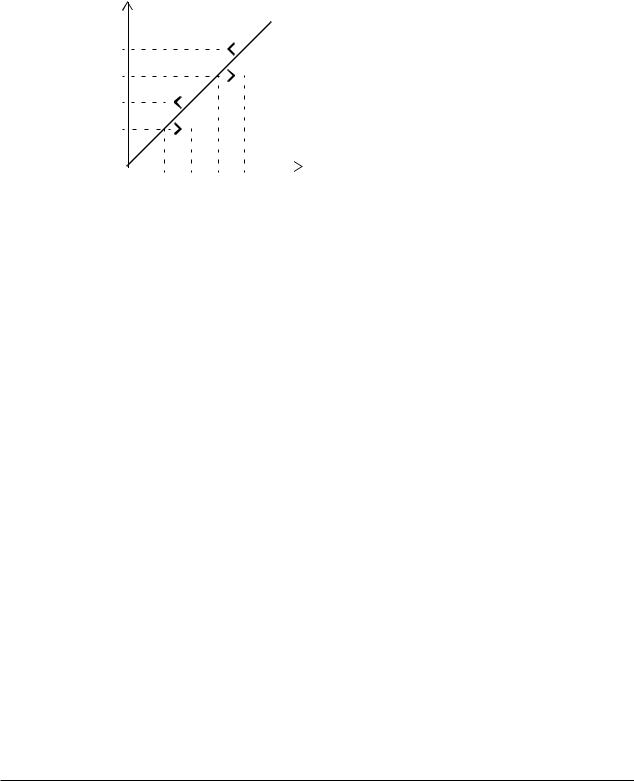
Example
A fan has vibrations in the range of 540 to 690 rpm and 1380 to 1560 rpm. To make the drive jump over these speed ranges,
•enable the critical speeds function by turning on bit 0 of parameter 22.51 Critical speed function, and
•set the critical speed ranges as in the figure below.
Motor speed (rpm)
1560 |
|
|
|
|
|
|
1 |
Par. 22.52 |
= 540 rpm |
|
|
|
|
|
|
|
|
|
|
|
|
|
|
|
|
|
|
|
2 |
Par. 22.53 |
= 690 rpm |
|
|
|
|
|
|
|
|
||||
|
|
|
|
|
|
|
||||
1380 |
|
|
|
|
|
|
|
|
|
|
|
|
|
|
|
|
|
3 |
Par. 22.54 |
= 1380 rpm |
|
|
|
|
|
|
|
|
||||
|
|
|
|
|
|
|
||||
690 |
|
|
|
|
|
|
|
|
|
|
|
|
|
|
|
|
4 |
Par. 22.55 |
= 1560 rpm |
||
|
|
|
|
|
||||||
540 |
|
|
|
|
|
|
|
|
|
|
|
|
|
|
|
|
|
|
|
|
|
|
|
|
|
|
|
|
|
|
|
|
|
|
|
|
|
|
|
|
|
|
|
1 2 3 4 |
Speed reference |
|
|
|||||||
|
|
|
|
|
|
(rpm) |
|
|
||
Settings
Parameter groups 22 Speed reference selection (page 113) and 28 Frequency reference chain (page 135).
Encoder support
The program supports two single-turn or multiturn encoders (or resolvers). The following optional interface modules are available:
•Absolute encoder interface FEN-11: absolute encoder input, TTL input, TTL output (for encoder emulation and echo) and two digital inputs for position latching
•Resolver interface FEN-21: resolver input, TTL input, TTL output (for encoder emulation echo) and two digital inputs for position latching
•HTL encoder interface FEN-31: HTL encoder input, TTL output (for encoder emulation and echo) and two digital inputs for position latching.
The interface module is installed onto any option slot on the drive control unit, or onto an FEA-xx extension adapter.
Quick configuration of HTL encoder feedback
1.Specify the type of the encoder interface module (parameter 91.11 Module 1 type = FEN-31) and the slot the module is installed into (91.12 Module 1 location).
2.Specify the type of the encoder (92.01 Encoder 1 type = HTL). The parameter listing will be re-read from the drive after the value is changed.
Loading...