


ACS800-37-0100-3
Table of contents
 Loading...
ABB ACS800-37-0100-3, ACS800-37-0260-3, ACS800-37-0210-3, ACS800-37-0070-3, ACS800-37-0320-3 Hardware Manual
...
ACS800
Hardware Manual
ACS800-37 Dri ves (55 to 2700 kW / 75 to 3000 HP)


ACS800-37 Drives
55 to 2700 kW (75 to 3000 HP)
Hardware Manual
© 2005 ABB Oy. All Rights Reserved.
3AFE68557925 R EV B EN
EFFECTIVE: 01.1 1.2005

Safety instructions
What this chapter contains
This chapter contains safety instructions you must follow when installing, operating
and servicing the drive. If igno red, physic al injury or d eat h may follow, or damage
may occur to the drive, the motor or driven equipment. Read the safety instructions
before yo u w ork on the unit .
Usage of warnings and notes
There are t w o t y pes of s af et y ins t r uctions throughout th is m anual: wa rnings and
notes. Warnings caution you about conditions which can result in serious injury or
death and/ or damage to the equip m ent, and adv is e on how to av oid the dang er.
Notes draw attention to a particular condition or fact, or give information on a
subject. The warning symbols are used as follows:
5
Dangerous voltage warning warns of high voltages which can cause
physical injury and/or damage to the equipment.
Genera l warning warns about condit ions, other than thos e c aused by
electricity, which can result in physical injury and/or damage to the
equipment.
Electrostatic discharge warning warns of electrostatic disch arge which
can damage the equipment.
Safety instructions

6
Installation and maintenance work
These warnings ar e int ended for all who work on the drive, m ot or c able or motor.
Ignoring the instructions can cause physical injury or death, or damage the
equipment.
WARNING!
Only qualif ied electric ians are allowed to install and maintain the drive.
•
The main switch o n the cabi net doo r does not r emove the volta ge from th e input
•
busbars of the drive. Before working on the drive, isolate the whole drive from
the s u pply.
Never work on the drive, the motor cable or the motor when main power is
•
applied. After switching off the input power, always wait for 5 min to let the
intermediate circuit capacitors discharge before you start working on the drive,
the motor or the motor cable. Measure the voltage between terminals UDC+
and UDC- (L+ and L–) with a multimeter (impedance at least 1 Mohm) to
ensure tha t th e drive is discharged be f ore beginning work.
Apply temporary gro unding bef ore working on the unit .
•
Do not work on t he control c ables whe n po wer is appli ed to the drive or t o t he
•
external control circuits. Externally supplied control circuits may cause
dangero us vo lta ges to exi st insi de t he drive ev en when the m ain power of the
drive is switched off.
Do not make any insulation or voltage withstand tests on the drive or drive
•
modules.
When reco nnecting th e m otor cable, always ch ec k th at th e phase ord er is
•
correct.
When joining shipping splits (if any), check the cable connections at the joints
•
before swit c hing on the supply vol tag e.
Live parts on the ins ide of the doors are prot ec t ed agains t di rect contact .
•
Special attention sh all be paid whe n handling m eta llic s hrouds.
Note:
The motor cable terminals on the drive are at a dangerously high voltage when
•
the input power is on, regardless of whether the motor is running or not.
The brake control terminals (UDC+, UDC-, R+ and R- terminals) carry a
•
dangero us D C vo ltag e (over 500 V ).
Safety instructions
Depending on the ext ernal wiring, danger ous voltages (115 V, 220 V or 230 V)
•
may be present on the relay outputs of the drive system.
The Prevention of Unexpected Start function does not remove the voltage from
•
the main an d auxiliary ci rc uits.
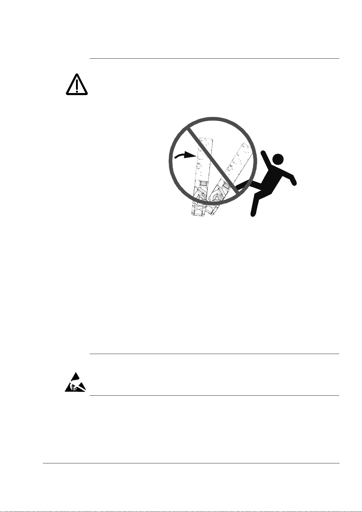
WARNING!
During the installation procedure, supply, filter or inverter modules may have to
•
be temp orarily extra c te d from the c abinet. The mo dules hav e a high centre of
gravity. In order to minimise the danger of to ppling over, keep th e s upport legs
(if provid ed) of the mo dules extended whe never manoeuvring the modules
outside the cabinet. An overturning module can cause physical injury.
Do not tilt!
7
Electrically conductive dust inside the unit may cause damage or lead to
•
malfun c tio n. M ak e sure that dus t fr om drilling do es not enter the driv e when
installing.
Fastening the cabinet by riveting or welding is not recommended. However, if
•
welding is necessary, ensure the return wire is properly connected in order not
to damage the electronic equipment in the cabinet. Also ensure that welding
fumes are not inhal ed.
Ensure sufficient cooling of the unit.
•
Cooling fans may continue to rotate for a while after the disconnection of the
•
electrical supply.
Some parts inside the drive cabinet, such as heatsinks of power
•
semiconductors, remain hot for a while after the disconnection of the electrical
supply.
WARNING!
The print ed circuit bo ards contain c omponen ts s ens it iv e to electrostatic
•
discharge. Wear a grounding wrist band when handling the boards. Do not
touch the boards unnecessarily.
Safety instructions

8
Grounding
These in structions a re intended for all who are respon si ble for the grounding o f the
drive. Incorrect grounding can cause physical injury, death or equipment malfunction
and increase electromagnetic interference.
WARNING!
Groun d t he drive, the motor and adjoining equipmen t to ens ure personnel
•
safety in all circumstances, and to reduce electromagnetic emission and pickup.
Make sure that gr ounding co nductors ar e adequately sized as required by
•
safety regulations.
In a multiple-drive installati on, con nect each drive separ at ely to protect ive
•
earth (PE).
Do not in stall a drive equ ipped with an EM C (line) filter to an un grounded
•
power system or a high resistance-grounded (over 30 o hms) power system.
Note:
Power c able shield s a re s uitable for equipment gro unding conductors only
•
when adequatel y sized to meet safety regu lat ions.
As the no rm al leakage cu rrent of the drive is higher than 3.5 m A AC or 10 mA
•
DC (stated by EN 50178, 5.2.11.1), a fixed protective earth connection is
required.
Fibre optic cables
WARNING!
Handle the fibre optic cables with care. When unplugging optic cables, always
•
grab the connector, not the cable itself. Do not touch the ends of the fibres with
bare hands as the fibre is extremely sensitive to dirt. The minimum allowed
bend radius is 25 mm (1 in.).
Safety instructions
Operation
These warnings are int ended for al l w ho plan the operation of the drive or op erate
the drive. Ignorin g the instructions can cause physical i n jur y or d eath or damage the
equipment.
WARNING!
Before adjusting the drive and putting it into service, make sure that the motor
•
and all driven equipment are suitable for operation throughout the speed range
provided by the drive . Th e drive can be adjusted t o operate the m otor at
speeds above and be low t he speed provided b y co nnecting the motor directly
to the power line.
Do not activate automatic fault reset functions of the Standard Application
•
Program if dangerous situations can occur. When activated, these functions
will reset th e drive and re s um e operatio n af te r a f ault.
Do not control the motor with the disconnecting device (means); instead, use
•
the control panel keys and , or commands via the I/O board of the drive.
The maxim um allowed number of charging cycles of the DC capac it ors (i.e.
power-ups by applying power) is five in ten min ut es .
9
Do not use t he Prevent ion of Unex pected Start featur e fo r s to pping the dr iv e
•
when the inverter unit(s) is running. Give a Stop command instead.
Note:
If an external sou rce fo r start command is selected and it is ON, the drive (wi th
•
S tan dard Ap pli cati on Pro gram) w ill s tar t imme diat ely af ter fault reset unles s the
drive is conf igured for 3-wire (a puls e) start/stop.
When the control location is not set to Local (L not shown in the status row of
•
the display), the stop key on the control panel will not stop the drive. To stop
the drive using the control panel, press the LOC/REM key and then the stop
key .
Safety instructions

10
Permanent magnet motor drives
These are additional warnings concerning permanent magnet motor drives.
WARNING! Do not work on the drive when the permanent magnet motor is rotating.
Also when the supply power is switched off, a rotating permanent magnet motor
feeds power to the intermediate circuit of the drive and also the supply connections
become liv e (even when the invert er is s to pped!).
Installation and maintenance work
• Disconnect the motor from the drive with a safety switch
and addi ti onally, if po s si ble,
• lock the motor shaft and ground the motor connection terminals temporarily by
connecting them together as well as to the PE.
Operation
Do not run the motor above the rated speed. Motor overspeed leads to overvoltage
which may result in explosion of the capacitors in the intermediate circuit of the drive.
Application program
Controlling a permanent magnet motor is only allowed using the ACS800 Permanent
Magnet Sy nc hronous Mo t or D riv e Application Prog ram, or usin g ot her application
programs in scalar control mode only.
Safety instructions

11
Ta b l e of c o nt ents
Safety in struction s
What this chapter contains . . . . . . . . . . . . . . . . . . . . . . . . . . . . . . . . . . . . . . . . . . . . . . . . . . . . . . . . 5
Usage of warnings and notes . . . . . . . . . . . . . . . . . . . . . . . . . . . . . . . . . . . . . . . . . . . . . . . . . . . . . . 5
Installat ion and maintenance w ork . . . . . . . . . . . . . . . . . . . . . . . . . . . . . . . . . . . . . . . . . . . . . . . . . . 6
Grounding . . . . . . . . . . . . . . . . . . . . . . . . . . . . . . . . . . . . . . . . . . . . . . . . . . . . . . . . . . . . . . . . 8
Fibre optic cables . . . . . . . . . . . . . . . . . . . . . . . . . . . . . . . . . . . . . . . . . . . . . . . . . . . . . . . . . . . 8
Operation . . . . . . . . . . . . . . . . . . . . . . . . . . . . . . . . . . . . . . . . . . . . . . . . . . . . . . . . . . . . . . . . . . . . . . 9
Permanent magnet motor drives . . . . . . . . . . . . . . . . . . . . . . . . . . . . . . . . . . . . . . . . . . . . . . . . . . . 10
Installation and maintenance work . . . . . . . . . . . . . . . . . . . . . . . . . . . . . . . . . . . . . . . . . . . . . 10
Operation . . . . . . . . . . . . . . . . . . . . . . . . . . . . . . . . . . . . . . . . . . . . . . . . . . . . . . . . . . . . . . . . 10
Application program . . . . . . . . . . . . . . . . . . . . . . . . . . . . . . . . . . . . . . . . . . . . . . . . . . . . . . . . 10
Table of contents
About this manual
What this chapter contains . . . . . . . . . . . . . . . . . . . . . . . . . . . . . . . . . . . . . . . . . . . . . . . . . . . . . . . 19
Target audience . . . . . . . . . . . . . . . . . . . . . . . . . . . . . . . . . . . . . . . . . . . . . . . . . . . . . . . . . . . . . . . 19
Common chapters for multiple products . . . . . . . . . . . . . . . . . . . . . . . . . . . . . . . . . . . . . . . . . . . . . 19
Categorization according to the frame size . . . . . . . . . . . . . . . . . . . . . . . . . . . . . . . . . . . . . . . . . . . 19
Contents . . . . . . . . . . . . . . . . . . . . . . . . . . . . . . . . . . . . . . . . . . . . . . . . . . . . . . . . . . . . . . . . . . . . . 1 9
Installation and commissioning flowchart . . . . . . . . . . . . . . . . . . . . . . . . . . . . . . . . . . . . . . . . . . . . 2 0
Inquiries . . . . . . . . . . . . . . . . . . . . . . . . . . . . . . . . . . . . . . . . . . . . . . . . . . . . . . . . . . . . . . . . . . . . . . 2 1
Terms and abbreviations . . . . . . . . . . . . . . . . . . . . . . . . . . . . . . . . . . . . . . . . . . . . . . . . . . . . . . . . . 22
The ACS 800-37
What this chapter contains . . . . . . . . . . . . . . . . . . . . . . . . . . . . . . . . . . . . . . . . . . . . . . . . . . . . . . . 23
The ACS800-37 . . . . . . . . . . . . . . . . . . . . . . . . . . . . . . . . . . . . . . . . . . . . . . . . . . . . . . . . . . . . . . . . 23
Cabinet line-up . . . . . . . . . . . . . . . . . . . . . . . . . . . . . . . . . . . . . . . . . . . . . . . . . . . . . . . . . . . . 23
Frame R6 . . . . . . . . . . . . . . . . . . . . . . . . . . . . . . . . . . . . . . . . . . . . . . . . . . . . . . . . . . . 24
Frame R7i . . . . . . . . . . . . . . . . . . . . . . . . . . . . . . . . . . . . . . . . . . . . . . . . . . . . . . . . . . . 25
Frame R8i . . . . . . . . . . . . . . . . . . . . . . . . . . . . . . . . . . . . . . . . . . . . . . . . . . . . . . . . . . . 26
Swing-out frame . . . . . . . . . . . . . . . . . . . . . . . . . . . . . . . . . . . . . . . . . . . . . . . . . . . . . . . . . . . 27
Cabling direction . . . . . . . . . . . . . . . . . . . . . . . . . . . . . . . . . . . . . . . . . . . . . . . . . . . . . . . . . . 29
Single-line circuit diagram of the drive . . . . . . . . . . . . . . . . . . . . . . . . . . . . . . . . . . . . . . . . . . . . . . 31
Operation principle . . . . . . . . . . . . . . . . . . . . . . . . . . . . . . . . . . . . . . . . . . . . . . . . . . . . . . . . . . . . . 3 2
Line-side converter . . . . . . . . . . . . . . . . . . . . . . . . . . . . . . . . . . . . . . . . . . . . . . . . . . . . . . . . 32
AC voltage and current waveforms . . . . . . . . . . . . . . . . . . . . . . . . . . . . . . . . . . . . . . . . 33
Motor-side converter . . . . . . . . . . . . . . . . . . . . . . . . . . . . . . . . . . . . . . . . . . . . . . . . . . . . . . . 34
Reduced run capability . . . . . . . . . . . . . . . . . . . . . . . . . . . . . . . . . . . . . . . . . . . . . . . . . . . . . 34
Controls . . . . . . . . . . . . . . . . . . . . . . . . . . . . . . . . . . . . . . . . . . . . . . . . . . . . . . . . . . . . . . . . . . . . . . 35
Control interfaces of the drive . . . . . . . . . . . . . . . . . . . . . . . . . . . . . . . . . . . . . . . . . . . . . . . . 35
Table of contents

12
Door switches . . . . . . . . . . . . . . . . . . . . . . . . . . . . . . . . . . . . . . . . . . . . . . . . . . . . . . . . . . . . .36
Main switch-disconnector (Q1 in frame size R6 to R8i) . . . . . . . . . . . . . . . . . . . . . . . . .36
Air circuit breaker (Q1 in frame size 2×R8i and up) . . . . . . . . . . . . . . . . . . . . . . . . . . . .3 6
Auxiliary power switch (Q100 in frame size 2×R8i and up) . . . . . . . . . . . . . . . . . . . . . .3 6
Earthing switch (Q9 in frame size 2×R8i and up) . . . . . . . . . . . . . . . . . . . . . . . . . . . . . 3 6
Other door switches . . . . . . . . . . . . . . . . . . . . . . . . . . . . . . . . . . . . . . . . . . . . . . . . . . . .36
Control panel . . . . . . . . . . . . . . . . . . . . . . . . . . . . . . . . . . . . . . . . . . . . . . . . . . . . . . . . . . . . . .3 7
To control the supply unit… . . . . . . . . . . . . . . . . . . . . . . . . . . . . . . . . . . . . . . . . . . . . . .37
To control the inverter unit… . . . . . . . . . . . . . . . . . . . . . . . . . . . . . . . . . . . . . . . . . . . . .37
Fieldbus control of the line-side converter . . . . . . . . . . . . . . . . . . . . . . . . . . . . . . . . . . . . . . .38
Block diagram: reference select . . . . . . . . . . . . . . . . . . . . . . . . . . . . . . . . . . . . . . . . . .38
Type code . . . . . . . . . . . . . . . . . . . . . . . . . . . . . . . . . . . . . . . . . . . . . . . . . . . . . . . . . . . . . . . . . . . . .39
Frame sizes R6, R7i and R8i . . . . . . . . . . . . . . . . . . . . . . . . . . . . . . . . . . . . . . . . . . . . . . . . .39
Frame sizes 2×R8i to 6×R8i . . . . . . . . . . . . . . . . . . . . . . . . . . . . . . . . . . . . . . . . . . . . . . . . . .40
Mecha n ic al i nsta llation
What this chapter contains . . . . . . . . . . . . . . . . . . . . . . . . . . . . . . . . . . . . . . . . . . . . . . . . . . . . . . . .43
General . . . . . . . . . . . . . . . . . . . . . . . . . . . . . . . . . . . . . . . . . . . . . . . . . . . . . . . . . . . . . . . . . . . . . . .43
Required tools . . . . . . . . . . . . . . . . . . . . . . . . . . . . . . . . . . . . . . . . . . . . . . . . . . . . . . . . . . . . . . . . .43
Moving the unit . . . . . . . . . . . . . . . . . . . . . . . . . . . . . . . . . . . . . . . . . . . . . . . . . . . . . . . . . . . . . . . . .44
…by crane . . . . . . . . . . . . . . . . . . . . . . . . . . . . . . . . . . . . . . . . . . . . . . . . . . . . . . . . . . . . . . . .4 4
…by fork-lift or pallet truck . . . . . . . . . . . . . . . . . . . . . . . . . . . . . . . . . . . . . . . . . . . . . . . . . . .4 5
…on rollers . . . . . . . . . . . . . . . . . . . . . . . . . . . . . . . . . . . . . . . . . . . . . . . . . . . . . . . . . . . . . . .45
Laying the unit on its back . . . . . . . . . . . . . . . . . . . . . . . . . . . . . . . . . . . . . . . . . . . . . . . . . . . . 4 5
Final placement of the unit . . . . . . . . . . . . . . . . . . . . . . . . . . . . . . . . . . . . . . . . . . . . . . . . . . .46
Before installation . . . . . . . . . . . . . . . . . . . . . . . . . . . . . . . . . . . . . . . . . . . . . . . . . . . . . . . . . . . . . . .47
Delivery check . . . . . . . . . . . . . . . . . . . . . . . . . . . . . . . . . . . . . . . . . . . . . . . . . . . . . . . . . . . . .47
Installation procedure . . . . . . . . . . . . . . . . . . . . . . . . . . . . . . . . . . . . . . . . . . . . . . . . . . . . . . . . . . . . 4 8
Fastening the cabinet to the floor (Non-marine units) . . . . . . . . . . . . . . . . . . . . . . . . . . . . . . . . . . .49
Clamping . . . . . . . . . . . . . . . . . . . . . . . . . . . . . . . . . . . . . . . . . . . . . . . . . . . . . . . . . . . . . . . . .49
Holes inside the cabinet . . . . . . . . . . . . . . . . . . . . . . . . . . . . . . . . . . . . . . . . . . . . . . . . . . . . .50
Fastening the unit to the floor and wall (Marine units) . . . . . . . . . . . . . . . . . . . . . . . . . . . . . . . . . . .51
Joining the shipping splits . . . . . . . . . . . . . . . . . . . . . . . . . . . . . . . . . . . . . . . . . . . . . . . . . . . . . . . .52
Procedure . . . . . . . . . . . . . . . . . . . . . . . . . . . . . . . . . . . . . . . . . . . . . . . . . . . . . . . . . . . . . . . .52
Connecting the DC busbars and the PE busbar . . . . . . . . . . . . . . . . . . . . . . . . . . . . . . . . . . .53
DC busbars . . . . . . . . . . . . . . . . . . . . . . . . . . . . . . . . . . . . . . . . . . . . . . . . . . . . . . . . . .54
PE busbar . . . . . . . . . . . . . . . . . . . . . . . . . . . . . . . . . . . . . . . . . . . . . . . . . . . . . . . . . . .54
Miscellaneous . . . . . . . . . . . . . . . . . . . . . . . . . . . . . . . . . . . . . . . . . . . . . . . . . . . . . . . . . . . . . . . . . .5 5
Cable conduit in the floor below the cabinet . . . . . . . . . . . . . . . . . . . . . . . . . . . . . . . . . . . . . .55
Cooling air intake through bottom of cabinet . . . . . . . . . . . . . . . . . . . . . . . . . . . . . . . . . . . . . .56
Example . . . . . . . . . . . . . . . . . . . . . . . . . . . . . . . . . . . . . . . . . . . . . . . . . . . . . . . . . . . . .5 6
Electric welding . . . . . . . . . . . . . . . . . . . . . . . . . . . . . . . . . . . . . . . . . . . . . . . . . . . . . . . . . . . .57
Planni n g th e el ectrica l in stallation
What this chapter contains . . . . . . . . . . . . . . . . . . . . . . . . . . . . . . . . . . . . . . . . . . . . . . . . . . . . . . . .59
Motor selection and compatibility . . . . . . . . . . . . . . . . . . . . . . . . . . . . . . . . . . . . . . . . . . . . . . . . . . .59
Protecting the motor insulation and bearings . . . . . . . . . . . . . . . . . . . . . . . . . . . . . . . . . . . . .60
Requirements table . . . . . . . . . . . . . . . . . . . . . . . . . . . . . . . . . . . . . . . . . . . . . . . . . . . . . . . . .61
Table of contents

13
Permanent magnet synchronous motor . . . . . . . . . . . . . . . . . . . . . . . . . . . . . . . . . . . . . . . . . . . . . 64
Thermal overload and short-circuit protection . . . . . . . . . . . . . . . . . . . . . . . . . . . . . . . . . . . . . . . . . 64
Supply (AC line) cable short-circuit protection . . . . . . . . . . . . . . . . . . . . . . . . . . . . . . . . . . . . 6 5
Earth fault (Ground fault) protection . . . . . . . . . . . . . . . . . . . . . . . . . . . . . . . . . . . . . . . . . . . . . . . . 6 5
Emergency stop devices . . . . . . . . . . . . . . . . . . . . . . . . . . . . . . . . . . . . . . . . . . . . . . . . . . . . . . . . . 65
Restarting after an emergency stop . . . . . . . . . . . . . . . . . . . . . . . . . . . . . . . . . . . . . . . . . . . . 65
Prevention of unexpected start . . . . . . . . . . . . . . . . . . . . . . . . . . . . . . . . . . . . . . . . . . . . . . . . . . . . 6 6
Selecting the power cables . . . . . . . . . . . . . . . . . . . . . . . . . . . . . . . . . . . . . . . . . . . . . . . . . . . . . . . 6 7
General rules . . . . . . . . . . . . . . . . . . . . . . . . . . . . . . . . . . . . . . . . . . . . . . . . . . . . . . . . . . . . . 67
Alternative power cable types . . . . . . . . . . . . . . . . . . . . . . . . . . . . . . . . . . . . . . . . . . . . . . . . 68
Motor cable shield . . . . . . . . . . . . . . . . . . . . . . . . . . . . . . . . . . . . . . . . . . . . . . . . . . . . . . . . . 68
Additional US requirements . . . . . . . . . . . . . . . . . . . . . . . . . . . . . . . . . . . . . . . . . . . . . . . . . . 69
Conduit . . . . . . . . . . . . . . . . . . . . . . . . . . . . . . . . . . . . . . . . . . . . . . . . . . . . . . . . . . . . . 69
Armored cable / shielded power cable . . . . . . . . . . . . . . . . . . . . . . . . . . . . . . . . . . . . . 69
Power factor compensation capacitors . . . . . . . . . . . . . . . . . . . . . . . . . . . . . . . . . . . . . . . . . . . . . . 70
Equipment connected to the motor cable . . . . . . . . . . . . . . . . . . . . . . . . . . . . . . . . . . . . . . . . . . . . 70
Installation of safety switches, contactors, connection boxes, etc. . . . . . . . . . . . . . . . . . . . . 70
Bypass connection . . . . . . . . . . . . . . . . . . . . . . . . . . . . . . . . . . . . . . . . . . . . . . . . . . . . 70
Before opening an output contactor (in DTC motor control mode) . . . . . . . . . . . . . . . . . . . . 7 1
Relay output contacts and inductive loads . . . . . . . . . . . . . . . . . . . . . . . . . . . . . . . . . . . . . . . . . . . 71
Selecting the control cables . . . . . . . . . . . . . . . . . . . . . . . . . . . . . . . . . . . . . . . . . . . . . . . . . . . . . . 72
Relay cable . . . . . . . . . . . . . . . . . . . . . . . . . . . . . . . . . . . . . . . . . . . . . . . . . . . . . . . . . . . . . . 72
Control panel cable . . . . . . . . . . . . . . . . . . . . . . . . . . . . . . . . . . . . . . . . . . . . . . . . . . . . . . . . 72
Coaxial cable (for use with Advant Controllers AC 80/AC 800) . . . . . . . . . . . . . . . . . . . . . . . 7 2
Connection of a motor temperature sensor to the drive I/O . . . . . . . . . . . . . . . . . . . . . . . . . . . . . . 7 3
Installation sites above 2000 metres (6562 feet) . . . . . . . . . . . . . . . . . . . . . . . . . . . . . . . . . . . . . . . 73
Routing the cables . . . . . . . . . . . . . . . . . . . . . . . . . . . . . . . . . . . . . . . . . . . . . . . . . . . . . . . . . . . . . . 73
Control cable ducts . . . . . . . . . . . . . . . . . . . . . . . . . . . . . . . . . . . . . . . . . . . . . . . . . . . . . . . . 74
Electrical installation
What this chapter contains . . . . . . . . . . . . . . . . . . . . . . . . . . . . . . . . . . . . . . . . . . . . . . . . . . . . . . . 75
Option coding . . . . . . . . . . . . . . . . . . . . . . . . . . . . . . . . . . . . . . . . . . . . . . . . . . . . . . . . . . . . . . . . . 7 5
Before installation . . . . . . . . . . . . . . . . . . . . . . . . . . . . . . . . . . . . . . . . . . . . . . . . . . . . . . . . . . . . . . 76
Checking the insulation of the assembly . . . . . . . . . . . . . . . . . . . . . . . . . . . . . . . . . . . . . . . . 76
IT (ungrounded) systems . . . . . . . . . . . . . . . . . . . . . . . . . . . . . . . . . . . . . . . . . . . . . . . . . . . . 76
Input power connection – Frame R6 . . . . . . . . . . . . . . . . . . . . . . . . . . . . . . . . . . . . . . . . . . . . . . . . 7 7
Connection diagram . . . . . . . . . . . . . . . . . . . . . . . . . . . . . . . . . . . . . . . . . . . . . . . . . . . . . . . . 77
Connection procedure . . . . . . . . . . . . . . . . . . . . . . . . . . . . . . . . . . . . . . . . . . . . . . . . . . . . . . 77
Input power connection – Frame R7i . . . . . . . . . . . . . . . . . . . . . . . . . . . . . . . . . . . . . . . . . . . . . . . 78
Connection diagram . . . . . . . . . . . . . . . . . . . . . . . . . . . . . . . . . . . . . . . . . . . . . . . . . . . . . . . . 78
Connection procedure . . . . . . . . . . . . . . . . . . . . . . . . . . . . . . . . . . . . . . . . . . . . . . . . . . . . . . 78
Input power connection – Frame size R8i . . . . . . . . . . . . . . . . . . . . . . . . . . . . . . . . . . . . . . . . . . . . 79
Connection diagram . . . . . . . . . . . . . . . . . . . . . . . . . . . . . . . . . . . . . . . . . . . . . . . . . . . . . . . . 79
Connection procedure . . . . . . . . . . . . . . . . . . . . . . . . . . . . . . . . . . . . . . . . . . . . . . . . . . . . . . 79
Input power connection – Frame size 2×R8i and up . . . . . . . . . . . . . . . . . . . . . . . . . . . . . . . . . . . . 80
Connection diagram . . . . . . . . . . . . . . . . . . . . . . . . . . . . . . . . . . . . . . . . . . . . . . . . . . . . . . . . 80
Connection procedure . . . . . . . . . . . . . . . . . . . . . . . . . . . . . . . . . . . . . . . . . . . . . . . . . . . . . . 80
Motor connection – Frame R6 . . . . . . . . . . . . . . . . . . . . . . . . . . . . . . . . . . . . . . . . . . . . . . . . . . . . . 81
Connection diagram . . . . . . . . . . . . . . . . . . . . . . . . . . . . . . . . . . . . . . . . . . . . . . . . . . . . . . . . 81
Table of contents

14
Connection procedure . . . . . . . . . . . . . . . . . . . . . . . . . . . . . . . . . . . . . . . . . . . . . . . . . . . . . . .81
Motor connection – Frame R7i . . . . . . . . . . . . . . . . . . . . . . . . . . . . . . . . . . . . . . . . . . . . . . . . . . . . .82
Connection diagram . . . . . . . . . . . . . . . . . . . . . . . . . . . . . . . . . . . . . . . . . . . . . . . . . . . . . . . .82
Connection procedure . . . . . . . . . . . . . . . . . . . . . . . . . . . . . . . . . . . . . . . . . . . . . . . . . . . . . . .82
Motor connection – Frame R8i units without option +E202 or +H359 . . . . . . . . . . . . . . . . . . . . . . .8 3
Connection diagram . . . . . . . . . . . . . . . . . . . . . . . . . . . . . . . . . . . . . . . . . . . . . . . . . . . . . . . .83
Connection procedure . . . . . . . . . . . . . . . . . . . . . . . . . . . . . . . . . . . . . . . . . . . . . . . . . . . . . . .83
Motor connection – Frame R8i with option +E202 but without +H359 . . . . . . . . . . . . . . . . . . . . . . . 84
Output busbars . . . . . . . . . . . . . . . . . . . . . . . . . . . . . . . . . . . . . . . . . . . . . . . . . . . . . . . . . . . .84
Connection diagram . . . . . . . . . . . . . . . . . . . . . . . . . . . . . . . . . . . . . . . . . . . . . . . . . . . . . . . .84
Connection procedure . . . . . . . . . . . . . . . . . . . . . . . . . . . . . . . . . . . . . . . . . . . . . . . . . . . . . . .84
Motor connection – Units with common motor terminal cubicle (+H359) . . . . . . . . . . . . . . . . . . . . . 8 7
Connection diagram . . . . . . . . . . . . . . . . . . . . . . . . . . . . . . . . . . . . . . . . . . . . . . . . . . . . . . . .87
Connection procedure . . . . . . . . . . . . . . . . . . . . . . . . . . . . . . . . . . . . . . . . . . . . . . . . . . . . . . .87
Motor connection – Frame 2×R8i and up without common motor terminal cubicle . . . . . . . . . . . . .88
Output busbars . . . . . . . . . . . . . . . . . . . . . . . . . . . . . . . . . . . . . . . . . . . . . . . . . . . . . . . . . . . .88
Connection diagram . . . . . . . . . . . . . . . . . . . . . . . . . . . . . . . . . . . . . . . . . . . . . . . . . . . . . . . .88
Connection procedure . . . . . . . . . . . . . . . . . . . . . . . . . . . . . . . . . . . . . . . . . . . . . . . . . . . . . . .89
Control connections . . . . . . . . . . . . . . . . . . . . . . . . . . . . . . . . . . . . . . . . . . . . . . . . . . . . . . . . . . . . .91
Drive control connections . . . . . . . . . . . . . . . . . . . . . . . . . . . . . . . . . . . . . . . . . . . . . . . . . . . .91
Supply unit control connections . . . . . . . . . . . . . . . . . . . . . . . . . . . . . . . . . . . . . . . . . . .91
Connection procedure . . . . . . . . . . . . . . . . . . . . . . . . . . . . . . . . . . . . . . . . . . . . . . . . . . . . . .91
Installation of optional modules and PC . . . . . . . . . . . . . . . . . . . . . . . . . . . . . . . . . . . . . . . . . . . . . .93
Cabling of I/O and fieldbus modules . . . . . . . . . . . . . . . . . . . . . . . . . . . . . . . . . . . . . . . . . . . .93
Cabling of pulse encoder interface module . . . . . . . . . . . . . . . . . . . . . . . . . . . . . . . . . . . . . . .93
Fibre optic links . . . . . . . . . . . . . . . . . . . . . . . . . . . . . . . . . . . . . . . . . . . . . . . . . . . . . . . . . . . .93
Tap settings of the auxiliary voltage transformer (Frame R8i and up) . . . . . . . . . . . . . . . . . . . . . . .94
Installation of brake resistors . . . . . . . . . . . . . . . . . . . . . . . . . . . . . . . . . . . . . . . . . . . . . . . . . . . . . .94
Motor control and I/O board (RMIO)
What this chapter contains . . . . . . . . . . . . . . . . . . . . . . . . . . . . . . . . . . . . . . . . . . . . . . . . . . . . . . . .95
To which products this chapter applies . . . . . . . . . . . . . . . . . . . . . . . . . . . . . . . . . . . . . . . . . . . . . .95
Note on cabinet-installed ACS800 drives . . . . . . . . . . . . . . . . . . . . . . . . . . . . . . . . . . . . . . . . . . . . .95
Note on terminal labelling . . . . . . . . . . . . . . . . . . . . . . . . . . . . . . . . . . . . . . . . . . . . . . . . . . . . . . . . .95
External control connections (non-US) . . . . . . . . . . . . . . . . . . . . . . . . . . . . . . . . . . . . . . . . . .96
External control connections (US) . . . . . . . . . . . . . . . . . . . . . . . . . . . . . . . . . . . . . . . . . . . . . . 9 7
RMIO board specifications . . . . . . . . . . . . . . . . . . . . . . . . . . . . . . . . . . . . . . . . . . . . . . . . . . . . . . . .98
Analogue inputs . . . . . . . . . . . . . . . . . . . . . . . . . . . . . . . . . . . . . . . . . . . . . . . . . . . . . . . . . . .98
Constant voltage output . . . . . . . . . . . . . . . . . . . . . . . . . . . . . . . . . . . . . . . . . . . . . . . . . . . . .98
Auxiliary power output . . . . . . . . . . . . . . . . . . . . . . . . . . . . . . . . . . . . . . . . . . . . . . . . . . . . . . .98
Analogue outputs . . . . . . . . . . . . . . . . . . . . . . . . . . . . . . . . . . . . . . . . . . . . . . . . . . . . . . . . . .98
Digital inputs . . . . . . . . . . . . . . . . . . . . . . . . . . . . . . . . . . . . . . . . . . . . . . . . . . . . . . . . . . . . . .9 8
Relay outputs . . . . . . . . . . . . . . . . . . . . . . . . . . . . . . . . . . . . . . . . . . . . . . . . . . . . . . . . . . . . .99
DDCS fibre optic link . . . . . . . . . . . . . . . . . . . . . . . . . . . . . . . . . . . . . . . . . . . . . . . . . . . . . . . .99
24 VDC power input . . . . . . . . . . . . . . . . . . . . . . . . . . . . . . . . . . . . . . . . . . . . . . . . . . . . . . . .99
Installation checklist and start-up
What this chapter contains . . . . . . . . . . . . . . . . . . . . . . . . . . . . . . . . . . . . . . . . . . . . . . . . . . . . . . .101
Table of contents

15
Installation checklist . . . . . . . . . . . . . . . . . . . . . . . . . . . . . . . . . . . . . . . . . . . . . . . . . . . . . . . . . . . 101
Start-up procedure . . . . . . . . . . . . . . . . . . . . . . . . . . . . . . . . . . . . . . . . . . . . . . . . . . . . . . . . . . . . 102
Basic checks with no voltage connected . . . . . . . . . . . . . . . . . . . . . . . . . . . . . . . . . . . . . . . 102
Connec t ing voltage to input termin als and auxilia ry c i rc uit . . . . . . . . . . . . . . . . . . . . . . . . . 102
Starting the supply unit . . . . . . . . . . . . . . . . . . . . . . . . . . . . . . . . . . . . . . . . . . . . . . . . . . . . 103
Checks with the supply unit running . . . . . . . . . . . . . . . . . . . . . . . . . . . . . . . . . . . . . . . . . . 103
Supply (line-side converter) program set-up . . . . . . . . . . . . . . . . . . . . . . . . . . . . . . . . . . . . 103
Application program set-up . . . . . . . . . . . . . . . . . . . . . . . . . . . . . . . . . . . . . . . . . . . . . . . . . 103
On-load checks . . . . . . . . . . . . . . . . . . . . . . . . . . . . . . . . . . . . . . . . . . . . . . . . . . . . . . . . . . 103
ACS800-37-specific parameters in the IGBT Supply Control Program . . . . . . . . . . . . . . . . . . . . . 104
Terms and abbreviations . . . . . . . . . . . . . . . . . . . . . . . . . . . . . . . . . . . . . . . . . . . . . . . . . . . 104
Parameters . . . . . . . . . . . . . . . . . . . . . . . . . . . . . . . . . . . . . . . . . . . . . . . . . . . . . . . . . . . . . 104
Fixed parameters with the ACS800-37 . . . . . . . . . . . . . . . . . . . . . . . . . . . . . . . . . . . . . . . . 105
ACS800-37-specific parameters in the application program . . . . . . . . . . . . . . . . . . . . . . . . . . . . . 106
Terms and abbreviations . . . . . . . . . . . . . . . . . . . . . . . . . . . . . . . . . . . . . . . . . . . . . . . . . . . 106
Actual signals and parameters of line-side converter in motor-side converter program . . . 107
Maintenance
What this chapter contains . . . . . . . . . . . . . . . . . . . . . . . . . . . . . . . . . . . . . . . . . . . . . . . . . . . . . . 109
Safety instructions . . . . . . . . . . . . . . . . . . . . . . . . . . . . . . . . . . . . . . . . . . . . . . . . . . . . . . . . . . . . . 109
Maintenance intervals . . . . . . . . . . . . . . . . . . . . . . . . . . . . . . . . . . . . . . . . . . . . . . . . . . . . . . . . . . 109
Reduced run capability . . . . . . . . . . . . . . . . . . . . . . . . . . . . . . . . . . . . . . . . . . . . . . . . . . . . . . . . . 110
Checking and replacing the air filters . . . . . . . . . . . . . . . . . . . . . . . . . . . . . . . . . . . . . . . . . . . . . . 110
Quick connectors (Frame R8i and up) . . . . . . . . . . . . . . . . . . . . . . . . . . . . . . . . . . . . . . . . . . . . . 111
Cooling fans . . . . . . . . . . . . . . . . . . . . . . . . . . . . . . . . . . . . . . . . . . . . . . . . . . . . . . . . . . . . . . . . . 112
Supply/Inverter module cooling fan replacement (Frame R6) . . . . . . . . . . . . . . . . . . . . . . . 112
Supply/Inverter module cooling fan replacement (Frame R7i) . . . . . . . . . . . . . . . . . . . . . . . 113
LCL filter module cooling fan replacement (Frame R7i) . . . . . . . . . . . . . . . . . . . . . . . . . . . 114
Supply and inverter module cooling fan replacement (Frame R8i and up) . . . . . . . . . . . . . 115
Module fan replacement procedure . . . . . . . . . . . . . . . . . . . . . . . . . . . . . . . . . . . . . . 115
LCL filter cooling fan replacement (Frame R8i and up) . . . . . . . . . . . . . . . . . . . . . . . . . . . . 116
LCL filter fan replacement procedure . . . . . . . . . . . . . . . . . . . . . . . . . . . . . . . . . . . . . 116
Cabinet fan replacement (Frame R6) . . . . . . . . . . . . . . . . . . . . . . . . . . . . . . . . . . . . . . . . . 117
Cabinet fan replacement (Frame R8i and up with IP21-42) . . . . . . . . . . . . . . . . . . . . . . . . . 117
Cabinet fan replacement (Frame R8i and up with IP54) . . . . . . . . . . . . . . . . . . . . . . . . . . . 118
Heatsinks . . . . . . . . . . . . . . . . . . . . . . . . . . . . . . . . . . . . . . . . . . . . . . . . . . . . . . . . . . . . . . . . . . . . 119
Capacitors . . . . . . . . . . . . . . . . . . . . . . . . . . . . . . . . . . . . . . . . . . . . . . . . . . . . . . . . . . . . . . . . . . . 119
Reforming . . . . . . . . . . . . . . . . . . . . . . . . . . . . . . . . . . . . . . . . . . . . . . . . . . . . . . . . . . . . . . 119
Capacitor replacement . . . . . . . . . . . . . . . . . . . . . . . . . . . . . . . . . . . . . . . . . . . . . . . . . . . . . 119
Other maintenance actions . . . . . . . . . . . . . . . . . . . . . . . . . . . . . . . . . . . . . . . . . . . . . . . . . . . . . . 120
Power module replacement (Frame R8i and up) . . . . . . . . . . . . . . . . . . . . . . . . . . . . . . . . . 120
Fault Tracing
Faults and warnings displayed by the CDP-312R Control Panel . . . . . . . . . . . . . . . . . . . . . . . . . 121
Warning/Fault message from unit not being monitored by control panel . . . . . . . . . . . . . . . 121
Conflicting ID numbers . . . . . . . . . . . . . . . . . . . . . . . . . . . . . . . . . . . . . . . . . . . . . . . . . . . . . 121
LEDs of the drive . . . . . . . . . . . . . . . . . . . . . . . . . . . . . . . . . . . . . . . . . . . . . . . . . . . . . . . . . . . . . . 122
Table of contents

16
Technical data
What this chapter contains . . . . . . . . . . . . . . . . . . . . . . . . . . . . . . . . . . . . . . . . . . . . . . . . . . . . . . .123
IEC ratings . . . . . . . . . . . . . . . . . . . . . . . . . . . . . . . . . . . . . . . . . . . . . . . . . . . . . . . . . . . . . . . . . . .123
Symbols . . . . . . . . . . . . . . . . . . . . . . . . . . . . . . . . . . . . . . . . . . . . . . . . . . . . . . . . . . . . . . . .124
Derating . . . . . . . . . . . . . . . . . . . . . . . . . . . . . . . . . . . . . . . . . . . . . . . . . . . . . . . . . . . . . . . . . 125
Temperature derating . . . . . . . . . . . . . . . . . . . . . . . . . . . . . . . . . . . . . . . . . . . . . . . . .125
Altitude derating . . . . . . . . . . . . . . . . . . . . . . . . . . . . . . . . . . . . . . . . . . . . . . . . . . . . . .125
NEMA ratings . . . . . . . . . . . . . . . . . . . . . . . . . . . . . . . . . . . . . . . . . . . . . . . . . . . . . . . . . . . . . . . . .126
Symbols . . . . . . . . . . . . . . . . . . . . . . . . . . . . . . . . . . . . . . . . . . . . . . . . . . . . . . . . . . . . . . . .127
ACS800-37 frame sizes and power module types . . . . . . . . . . . . . . . . . . . . . . . . . . . . . . . . . . . . .128
AC fuses . . . . . . . . . . . . . . . . . . . . . . . . . . . . . . . . . . . . . . . . . . . . . . . . . . . . . . . . . . . . . . . . . . . . .129
DC fuses . . . . . . . . . . . . . . . . . . . . . . . . . . . . . . . . . . . . . . . . . . . . . . . . . . . . . . . . . . . . . . . . . . . . .130
Input power connection . . . . . . . . . . . . . . . . . . . . . . . . . . . . . . . . . . . . . . . . . . . . . . . . . . . . . . . . .131
Motor connection . . . . . . . . . . . . . . . . . . . . . . . . . . . . . . . . . . . . . . . . . . . . . . . . . . . . . . . . . . . . . .133
Efficiency . . . . . . . . . . . . . . . . . . . . . . . . . . . . . . . . . . . . . . . . . . . . . . . . . . . . . . . . . . . . . . . . . . . .136
Cooling . . . . . . . . . . . . . . . . . . . . . . . . . . . . . . . . . . . . . . . . . . . . . . . . . . . . . . . . . . . . . . . . . . . . . . 136
Degrees of protection . . . . . . . . . . . . . . . . . . . . . . . . . . . . . . . . . . . . . . . . . . . . . . . . . . . . . . . . . . .136
Ambient conditions . . . . . . . . . . . . . . . . . . . . . . . . . . . . . . . . . . . . . . . . . . . . . . . . . . . . . . . . . . . . .136
Materials . . . . . . . . . . . . . . . . . . . . . . . . . . . . . . . . . . . . . . . . . . . . . . . . . . . . . . . . . . . . . . . . . . . . .137
Tightening torques for power connections . . . . . . . . . . . . . . . . . . . . . . . . . . . . . . . . . . . . . . . . . . .137
Applicable standards . . . . . . . . . . . . . . . . . . . . . . . . . . . . . . . . . . . . . . . . . . . . . . . . . . . . . . . . . . .137
CE marking . . . . . . . . . . . . . . . . . . . . . . . . . . . . . . . . . . . . . . . . . . . . . . . . . . . . . . . . . . . . . . . . . . .139
Definitions . . . . . . . . . . . . . . . . . . . . . . . . . . . . . . . . . . . . . . . . . . . . . . . . . . . . . . . . . . . . . . .139
Compliance with the EMC Directive . . . . . . . . . . . . . . . . . . . . . . . . . . . . . . . . . . . . . . . . . . .139
Compliance with the EN 61800-3 (2004) . . . . . . . . . . . . . . . . . . . . . . . . . . . . . . . . . . . . . . .139
First environment (drive of category C2) . . . . . . . . . . . . . . . . . . . . . . . . . . . . . . . . . . .139
Second environment (drive of category C3) . . . . . . . . . . . . . . . . . . . . . . . . . . . . . . . .140
Second environment (drive of category C4) . . . . . . . . . . . . . . . . . . . . . . . . . . . . . . . .140
Machinery Directive . . . . . . . . . . . . . . . . . . . . . . . . . . . . . . . . . . . . . . . . . . . . . . . . . . . . . . . .140
“C-tick” marking . . . . . . . . . . . . . . . . . . . . . . . . . . . . . . . . . . . . . . . . . . . . . . . . . . . . . . . . . . . . . . .141
Definitions . . . . . . . . . . . . . . . . . . . . . . . . . . . . . . . . . . . . . . . . . . . . . . . . . . . . . . . . . . . . . . .141
Compliance with the EN 61800-3 (2004) . . . . . . . . . . . . . . . . . . . . . . . . . . . . . . . . . . . . . . .141
First environment (drive of category C2) . . . . . . . . . . . . . . . . . . . . . . . . . . . . . . . . . . .141
Second environment (drive of category C3) . . . . . . . . . . . . . . . . . . . . . . . . . . . . . . . .142
Second environment (drive of category C4) . . . . . . . . . . . . . . . . . . . . . . . . . . . . . . . .142
Equipment warranty and liability . . . . . . . . . . . . . . . . . . . . . . . . . . . . . . . . . . . . . . . . . . . . . . . . . . .143
Dimensions
What this chapter contains . . . . . . . . . . . . . . . . . . . . . . . . . . . . . . . . . . . . . . . . . . . . . . . . . . . . . . .145
Weights . . . . . . . . . . . . . . . . . . . . . . . . . . . . . . . . . . . . . . . . . . . . . . . . . . . . . . . . . . . . . . . . . . . . .145
Frame R6 . . . . . . . . . . . . . . . . . . . . . . . . . . . . . . . . . . . . . . . . . . . . . . . . . . . . . . . . . . . . . . . . . . . . 146
Frame R7i . . . . . . . . . . . . . . . . . . . . . . . . . . . . . . . . . . . . . . . . . . . . . . . . . . . . . . . . . . . . . . . . . . . .150
Frame R8i (without option +E202) . . . . . . . . . . . . . . . . . . . . . . . . . . . . . . . . . . . . . . . . . . . . . . . . .157
Frame size R8i (with option +E202) . . . . . . . . . . . . . . . . . . . . . . . . . . . . . . . . . . . . . . . . . . . . . . . . 165
Frame size 2×R8i . . . . . . . . . . . . . . . . . . . . . . . . . . . . . . . . . . . . . . . . . . . . . . . . . . . . . . . . . . . . . .170
Frame size 3×R8i . . . . . . . . . . . . . . . . . . . . . . . . . . . . . . . . . . . . . . . . . . . . . . . . . . . . . . . . . . . . . .183
Frame size 4×R8i . . . . . . . . . . . . . . . . . . . . . . . . . . . . . . . . . . . . . . . . . . . . . . . . . . . . . . . . . . . . . .189
Frame size 5×R8i . . . . . . . . . . . . . . . . . . . . . . . . . . . . . . . . . . . . . . . . . . . . . . . . . . . . . . . . . . . . . .195
Table of contents

17
Frame size 6×R8i . . . . . . . . . . . . . . . . . . . . . . . . . . . . . . . . . . . . . . . . . . . . . . . . . . . . . . . . . . . . . 207
Resistor b r aking
What this chapter contains . . . . . . . . . . . . . . . . . . . . . . . . . . . . . . . . . . . . . . . . . . . . . . . . . . . . . . 219
Resistor braking options . . . . . . . . . . . . . . . . . . . . . . . . . . . . . . . . . . . . . . . . . . . . . . . . . . . . . . . . 219
Chopper/Resistor combinations – Technical data . . . . . . . . . . . . . . . . . . . . . . . . . . . . . . . . 220
Brake choppers – Technical data . . . . . . . . . . . . . . . . . . . . . . . . . . . . . . . . . . . . . . . . . . . . 221
Brake resistors – Technical data . . . . . . . . . . . . . . . . . . . . . . . . . . . . . . . . . . . . . . . . . . . . . 221
Verifying the capacity of the braking equipment . . . . . . . . . . . . . . . . . . . . . . . . . . . . . . . . . . . . . . 222
Custom resistors . . . . . . . . . . . . . . . . . . . . . . . . . . . . . . . . . . . . . . . . . . . . . . . . . . . . . . . . . 222
Calculating the maximum braking power (P
) . . . . . . . . . . . . . . . . . . . . . . . . . . . . . . . . . . . 223
br
Example 1 . . . . . . . . . . . . . . . . . . . . . . . . . . . . . . . . . . . . . . . . . . . . . . . . . . . . . . . . . . 223
Example 2 . . . . . . . . . . . . . . . . . . . . . . . . . . . . . . . . . . . . . . . . . . . . . . . . . . . . . . . . . . 223
Example 3 . . . . . . . . . . . . . . . . . . . . . . . . . . . . . . . . . . . . . . . . . . . . . . . . . . . . . . . . . . 224
Custom resistor installation and wiring . . . . . . . . . . . . . . . . . . . . . . . . . . . . . . . . . . . . . . . . . . . . . 225
Brake circuit commissioning . . . . . . . . . . . . . . . . . . . . . . . . . . . . . . . . . . . . . . . . . . . . . . . . . . . . . 226
Table of contents

18
Table of contents

About this manual
What this chapter contains
This chapter describes the intended audience and contents of the manual. It
contains a flowchart of steps in checking the delivery, installing and commissioning
the drive. The flowchart refers to chapters/sections in this manual and other
manuals.
Target audience
This manual is intended for people who plan the installation, install, commission, use
and service the drive. R ead the ma nual before wo rk ing on the dr iv e. Th e reader is
expected to know the fundamentals of electricity, wiring, electrical components and
electrical schematic symbols.
The manual is written for readers worldwide. Both SI and imperial units are shown.
Special US instructions for installations within the United States that must be
installed pe r th e N at ional Elec tr ic al C ode and loc al c odes are m arked with (U S).
19
Common chapters for multiple products
Some chapters in this manual apply to several products including the ACS800-37.
Other product types may be mentioned in these chapters.
Categorization according to the frame size
Some ins tr uc t ions, technic al data and dim ensiona l drawings w hic h c oncern on ly
certain drive frame sizes are marked with the symbol of the frame size (such as
“2×R8 i”, et c .) . T he frame size is not marked on the drive designation lab el. To
identify the frame size of your drive, see the rating tables in chapter Tec hnical data.
Contents
The chap te rs of th is m anual are briefly desc ribed below.
Safety instructions gives safety instructions for the installation, commissioning,
oper at ion and mai ntenanc e of th e drive.
About this m anual introduces this manual.
The ACS800-37 descri bes the drive.
Mechan ic al installation ins t ruc ts ho w to move, place and mount the dr iv e.
Planning the electrical installation provides advice on motor and cable selecti o n, the
protective functions of the drive, and cable routing.
Electrical installation describes the cabling and wiring of t he drive.
About this manual
20
Motor control and I/O board (RMIO) shows external control connecti ons to the motor
control a nd I / O board and its s pecificat ions.
Installation checklist and start-up helps in checking the mechanical and electrical
installation of the drive.
Maintenance conta i ns preventi ve main tenance instructi o ns.
Fault Tracing contains troubleshoot ing instruc tio ns .
Technical data contains the technical specifications of the drive, e.g. ratings, frame
sizes and technical requirements, provisions for fulfilling the requirements for CE
and other m arkings and warran ty policy.
Dimensions contains information on the dimens ions of the dr iv e.
Resistor brakin g describes how to select, protect and wire optional brake choppers
and resistors.
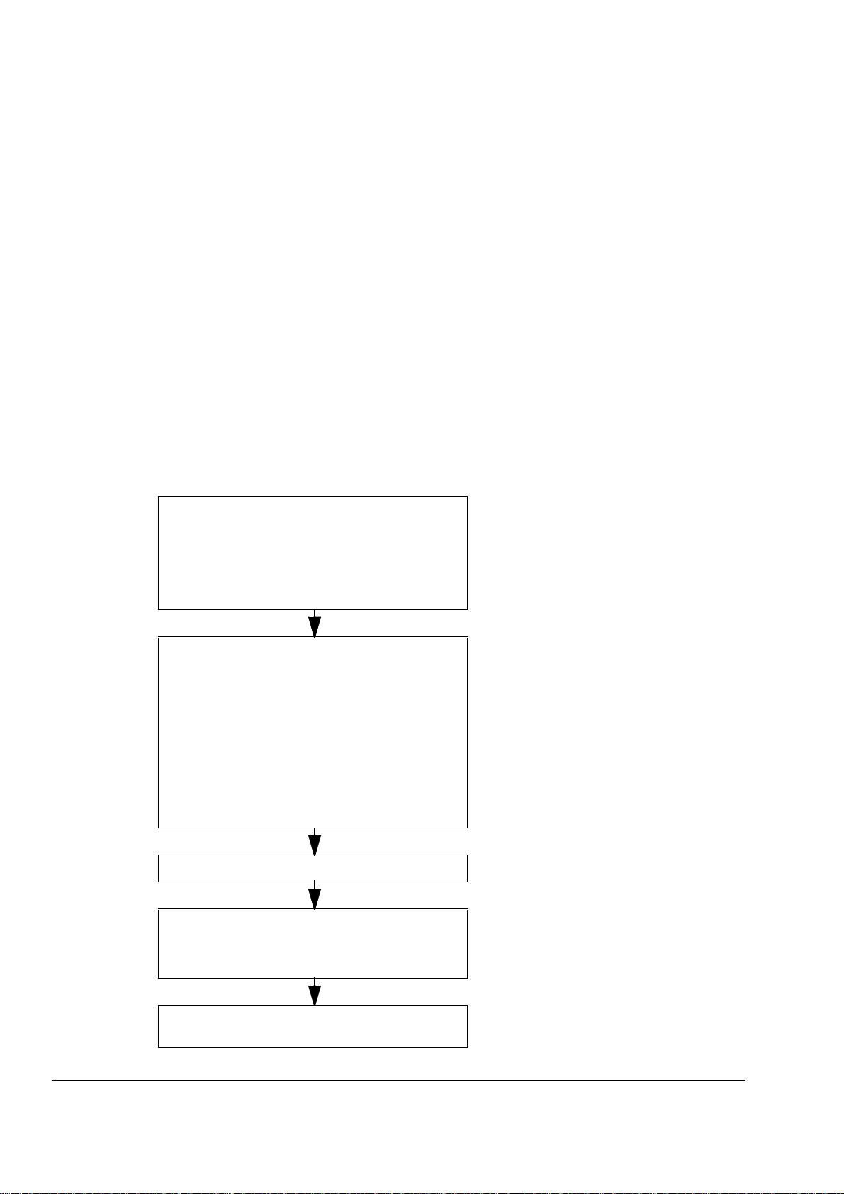
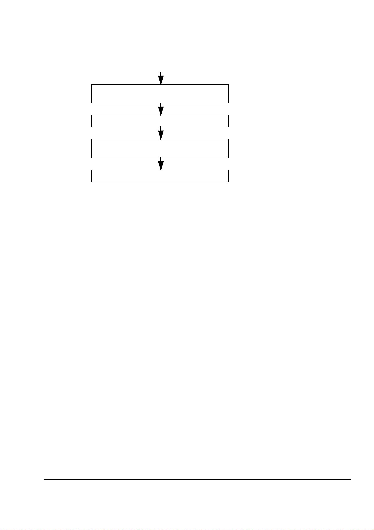
Installation an d co mmis sio n in g flo wch art
Task See
Plan the installation.
Check the ambient conditions, ratings, required
cooling ai r flow, input power connec ti on, compatibility
of the motor, motor connection, and other technical
data.
Select the cables.
Unpack and chec k the uni ts.
Check the type code indicated by the type
designati on label with the original order. If the drive is
about to be connect ed to an IT (ungr ounded) sy st em,
check that the drive is not equipped with EMC/RFI
filtering +E202. Check that all necessary optional
modules and equipment are present and correct.
Only intact units may be started up.
Check the inst all ation site. Mechanical inst allation, Technical data
T echnical data
Planning the electrical installat ion
Option manuals (if opti onal equipment is
included)
Mechanical inst allation
The ACS800-37
For instructions on how to disconnect the EMC/
RFI filtering, cont act your local ABB
representative.
If the converter has been non-operational for
more than one year, the converter DC link
capacitors need to be reformed. Contact your
local ABB representative for more information.
About this manual
Route the cables. Planning the electr ical installation: Routing the
cables
Mount the cabinet line-up. Mechanical inst allation
Check the insula ti on of the motor and the motor
cable.
Electrical in stallati on: Check ing the insu lation of
the assembly
Task See
21
Inquiries
Connect the power cables. Connect the control and
the auxiliary control cables.
Check the installation. Installation checklist and start-up
Commission the drive. Installation checklist and start-up and
Commission the brake chop per (if present). Resistor braking.
Mechanical installation, Pl anning the electrical
installation, Electrical ins tallation
appropriate firmware manual
Address any inquiri es ab ou t th e produc t to th e lo cal A BB r epr esent a ti ve , qu o ti ng th e
type code and serial n um ber of the unit . If th e local ABB representativ e ca nnot be
contacted, address inquiries to ABB Oy, AC Drives, PO Box 184, 00381 Helsinki,
Finland.
About this manual

22
Terms and abbrevi ations
Term/Abbreviation Explanation
AGPS Gate driver power supply board. An optional board within drives, used to
APBU Type of optical branching unit used for connecting p arallel-connected
CMF Common mode filtering.
DDCS Distributed Drives Communicati on System; a proto col used in optic al fibre
Drive unit See Motor-side converter.
EMC Ele ctromagnetic Compatibi lity.
Frame (size) Relates to the construction type of the component in question. For
implement the Preven ti on of Unexpected St art function.
converter modules to the RDCU.
communication inside and between ABB drives.
example, several drive types with different power ratings may have the
same basic construct ion, and this term is used in reference to all those
drive types.
With the ACS800-37 , the frame si ze of the drive i ndica tes the quant ity an d
frame size of the invert er modules, e.g. “2×R8i”.
To determine the frame size of a drive type, see the rating tables in the
chapter Technical data.
IGBT Insulated Gate Bipol ar Tra nsistor; a voltage- controlled semiconductor type
widely used in inverters because of their easy controllability and high
switching frequency.
IGBT supply unit (ISU) See Line-side converter.
Inverter unit (INU) See Motor-side converter.
Line-side conv erter A converter that is connected to the supply network and is capable of
transferring energy from the network to the DC link of the drive. With
ACS800-37 drives of frame si ze R7i and above, the line-side converter is
also called the (IGBT) supply unit or the ISU.
Motor-side converter A converter that is connected to the motor and control s the motor
operation. With ACS800-37 drives of frame size R7i and above, the
motor-side conve rter is also called the inverter unit or INU.
PPCS Power Plate Communication System; a protocol used in the optical fibre
link that controls the output semiconductors of an inverter module.
RDCU Drive control unit. The RDCU is a separate unit consi sting of an RMIO
board built in a plastic housing.
RFI Radio-Frequency Interference.
RMIO Motor control and I/O boar d. Contains the principal inputs and outputs of
the drive. The RMIO is contained within the RDCU drive control unit.
THD Total Harmonic Dist ortion.
About this manual

The ACS800-37
What this chapter contains
This chapter describes the construction of the drive in short.
The ACS800-37
The ACS8 00-37 is a cabinet-bui lt, low-harm onic drive fo r c ontrolling A C m ot ors.
Cabinet line-up
The drive consists of one or more cubicles that contain the supply and motor
terminals, 1 to 6 IGBT supply module(s) forming the line-side converter, 1 to 6
inverter modules forming the motor-side converter, and optional equipment. (Frame
R6 drives em ploy an integrated s upply/inv ert er module. ) T he actual arrangem ent of
the cubicles varies from type to type and the selected options. See also the chapter
Dimensions for the differ e nt li n e-up vari ati o n s.
23
The ACS800-37

24
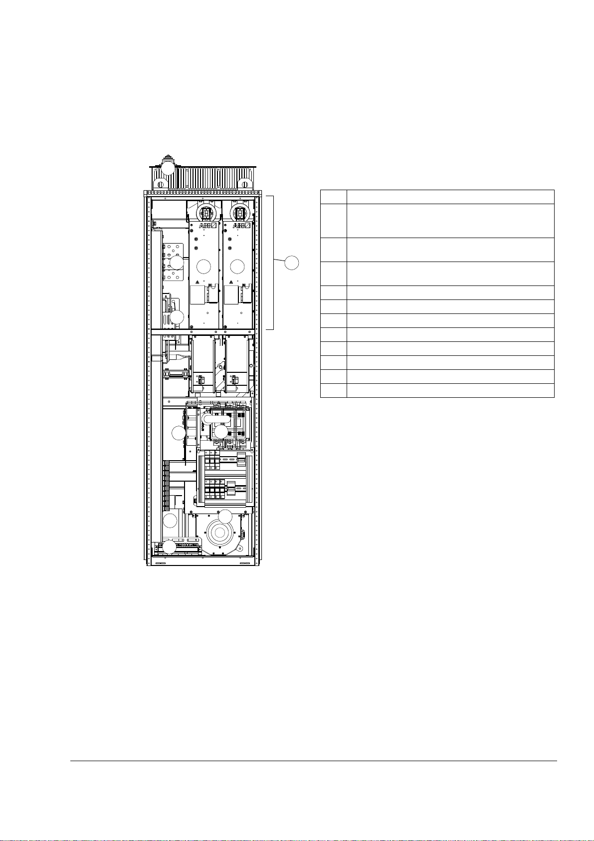
Fram e R6
The picture below shows the main components of a frame R6 drive with the door
open, and with the sw ing-out fra m e c losed (left) an d open (rig ht ).
3
12
3
No. Description
1 S wing-ou t fr am e (se e page 27)
12
8 108 10
4
4
6
2 Cable entries for power and control cables (bottom
cable entry/exit models)
3 Cable entries for power and control cables (top cable
entry/exit models)
4 Switch fuse
5 Auxiliary voltage transformer
6 Integrated line-side/motor- side converter module
7 Input terminals (bottom cable entry/exit models)
8 Input terminals (to p cable entry/exit models)
9 O utput ter m in al s ( bo tt o m ca bl e entry/ex it model s)
10 Output terminals (top cable entry/exi t models)
11 Control unit (RDCU) for motor-side converter
12 Cabinet cooling fan
11
1
2
The ACS800-37
7
9
55
2
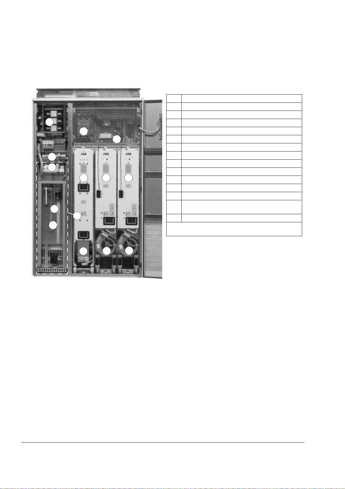
Frame R7i
The picture below shows the main components of a frame R7i drive with the door
and the swing-out frame open.
3
No. Description
1 Swing-out frame (see page 27) (not shown). The drive
control units for both converter modules are installed on
the swing-out fr ame.
2 Cable entries for power and control cables (bottom
11
10
8
6
1
cable entry/exit models)
3 Cable entries for power and control cables (top cable
entry/exit models)
4 Switch fuse
5 Auxiliary voltage transformer
6 Line-side converter module
7 LCL filter
8 Motor-side converter module
9 Input terminals
10 Output terminals (units without du/dt filtering +E205)
11 Output terminals (units with du/dt filtering +E205)
25
9
5
4
7
2
The ACS800-37
26
Frame R8i
4
2
3
14
13
The picture below shows the main components of a frame R8i drive with the doors
open.
No. Description
1 Swing-out frame (see picture on page 27)
2 Supply unit controller (RDCU)
3 Inverter unit controller (RDCU)
5
8
7
96
1
4 Switch-disconnector*
5 Input contactor*
6 LCL filter
7 IGBT supply module
8 Intermediate DC link
9 Inverter module
10 Cooling fan for LCL filter
11 Cooling fan for IGBT supply module
12 Cooling fan for inverter module
13 Auxiliary voltage trans former (accessible by opening
the swing-out frame)
14 Auxiliary voltage circuitry (relays etc.)
*In larger drives, an air ci rcuit breaker is used instead of the
switch-disconnector/contactor combination.
10
11
12
The ACS800-37
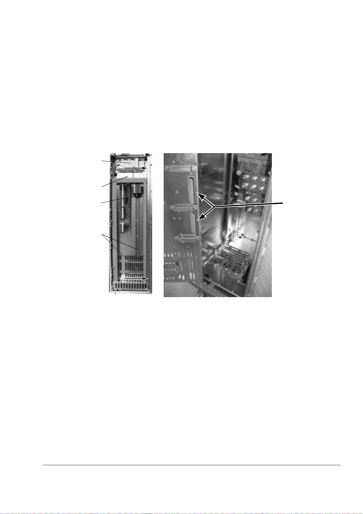
Swing-out frame
The swing-out frame provide s spa ce fo r t he c ontrol circu it r y of th e drive as wel l as
optio n al el e ctr ic al eq ui pm ent . Th e fr a me can be open ed by rem ov ing the tw o loc k ing
screws (a rrowed in the picture be low) and mov ing the swin g-out frame aside.
Depending on the fram e size of th e drive, the act ual equipm ent of the driv e may
differ from what is depicted.
27
Remove screw s (arrowed) to
open swing-out frame
Drive control unit
(RDCU) with I/O
terminal blocks
Spac e for optional
terminal block X2
Terminal block X1
Mounting rail s for
additional equipment
Swing-out frame open
I/O cable entries into
swing-out frame
The ACS800-37
28
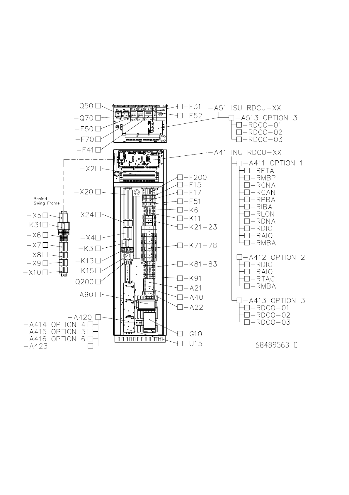
The following is a generic device layout diagram for the swing-out frame (drive frame
size R8i). The diagram is also attached to the inside of the cubicle door, with
installed devices marked. Refer to the circuit diagrams delivered with the drive for
device de s ignations.
The ACS800-37
Cabling direction
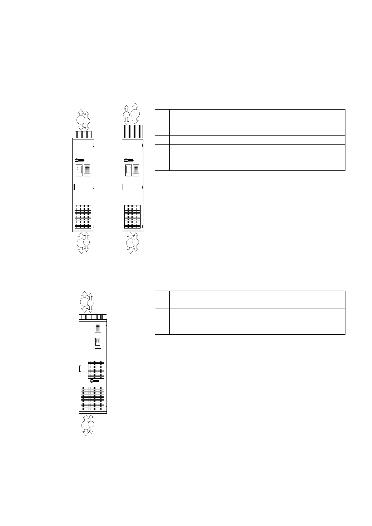
Frame size R6
29
The draw ing below shows the available po w er c abling direc t ions of the dr iv e.
2
5
4
1
Frame size R7i
3
6
IP54IP21-42
4
1
Description
1 Input/Motor output – Bottom entry
2 Input/Motor out put – Top entry (IP21-42)
3 Input/Motor out put – Top entry (IP54)
4 Signal cable input/output – Bottom entry
5 Signal cable input/output – Top entry (IP21-42 )
6 Signal cable input/output – Top entry (IP54)
Description
2
4
3
1
1 Input/Motor output – Bottom entry
2 Input/Motor output – Top entry
3 Signal cable input/output – Bottom entry
4 Signal cable input/output – Top entry
The ACS800-37
30
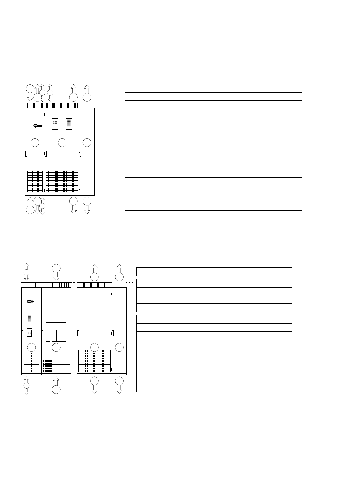
Frame size R8i
2
10
11
4
A C
3
9
1
B
567
Description
8
A Input/output cubi cl e
B Supply and inv er t er un it cu bi cl e
C Common motor terminal cubicle (optiona l)*
1 Standard input (bottom entry)
2 Standard input (top entry)
3 Standard out put (bott om exit)
4 Standard output (top exit)
5 Optiona l output (bottom exi t, 1st Environment)
6 Optional output (top exit, 1st Environment); additional depth 130 mm
7 Motor output – Bottom exit with common motor terminal cubicle (optional)*
8 Motor out put – Top exit with common motor terminal cubicl e (optional)*
9 Signal cable input/output – Bottom entry
10 Signal cabl e input/output – Top entry (IP54)
11 Signal cabl e input/output – Top entry (IP21-42)
*With EM C/RFI filtering for 1st Environment (+E202) onl y
Frame size 2×R8i and up
10
A
9
2
B
1
4
C D
3
6
Description
A Auxiliary c ontrol cubicle
B Incoming cubicle
C Inverter unit cubicle
D Common motor terminal cubicle (optional)
1 Standard input (bottom entry)
2 Standard input (top entry)
3 Standard output (bottom exit); at each inverter modu le
4 Standard output (top exit); at each inverter module
5 Motor output – Bottom exit with common motor terminal cubicle
(optional)
6 Motor output – Top exit with common motor t erminal cubicle
(optional)
5
9 Signal cable input/output – Bottom entry
10 Signal cable input/output – Top entry
The ACS800-37
Loading...