


ABB Micro drives
User’s manual
ACS255 drives (0.5…20 hp) (600V Variants)
List of related manuals
Option manuals and guides |
Code (English) |
|
|
ACS255 user’s manual for 115-480V variants |
3AXD10000528266 |
3
ACS255 drives
0.5…20 hp
User’s manual
3AXD10000528265 Rev A EN EFFECTIVE: 2016-09-13
© 2016 ABB Oy. All Rights Reserved.

5
1. Table of Contents
ACS255 – IP20 (600V Variants) |
EASY START-UP GUIDE ________________________________________ 7 |
ACS255 – IP66 (600V Variants) |
EASY START-UP GUIDE ________________________________________ 8 |
2.Safety ____________________________________________________________________________ 10
What this chapter contains _____________________________________________________________________ 10 Use of warnings ______________________________________________________________________________ 10 Safety in installation and maintenance____________________________________________________________ 10 Safety in start-up and operation _________________________________________________________________ 11
3.General Information and Ratings______________________________________________________ 13
3.1.Type designation key ___________________________________________________________________ 13
3.2.Drive model numbers – IP20 _____________________________________________________________ 14
3.3.Drive model numbers – IP66 _____________________________________________________________ 14
4.Mechanical Installation______________________________________________________________ 15
4.1.General ______________________________________________________________________________ 15
4.2.Before Installation _____________________________________________________________________ 15
4.3.UL Compliant Installation ________________________________________________________________ 15
4.4.Mechanical dimensions and weights _______________________________________________________ 15
4.5.Guidelines for Enclosure mounting (IP20 Units) ______________________________________________ 17
4.6.Mounting the Drive – IP20 Units __________________________________________________________ 17
4.7.Guidelines for mounting (IP66 Units)_______________________________________________________ 18
4.8.Removing the Terminal Cover ____________________________________________________________ 18
4.9.Routine Maintenance ___________________________________________________________________ 18
5.Electrical Installation________________________________________________________________ 19
5.1.Grounding the Drive ____________________________________________________________________ 19
5.2.Wiring Precautions _____________________________________________________________________ 20
5.3.Incoming Power Connection______________________________________________________________ 20
5.4.Compatibility with IT (ungrounded) and corner-grounded TN systems ____________________________ 21
5.5.Drive and Motor Connection _____________________________________________________________ 22
5.6.Motor Terminal Box Connections__________________________________________________________ 22
___________________________________________________________________________________________ 22
5.7.Motor Thermal overload Protection. _______________________________________________________ 22
5.8.Control Terminal Wiring _________________________________________________________________ 22
5.9.Connection Diagram ____________________________________________________________________ 23
5.10.Safe Torque Off ________________________________________________________________________ 24
6.Managing the Keypad_______________________________________________________________ 28
6.1.Keypad Layout and Function _____________________________________________________________ 28
6.2.Changing Parameters ___________________________________________________________________ 28
6
6.3.Resetting Parameters to Factory Default Settings_____________________________________________ 29
6.4.Advanced Keypad Operation ShortCuts_____________________________________________________ 30
6.5.Drive Operating Displays ________________________________________________________________ 30
7.Quick Start-up and Control ___________________________________________________________ 31
7.1.Quick Start-up Terminal Control __________________________________________________________ 31
7.2.Quick Start-up Keypad Control____________________________________________________________ 31
7.3.Sensorless Vector Speed Control Mode _____________________________________________________ 32
8.Application Macros _________________________________________________________________ 33
8.1.Overview of macros ____________________________________________________________________ 33
8.2.Macro wiring configurations. _____________________________________________________________ 34
9.Parameters _______________________________________________________________________ 38
9.1.Parameter Structure ____________________________________________________________________ 38
9.2.Parameters in the Short parameter mode___________________________________________________ 39
9.3.Read Only Status parameters_____________________________________________________________ 41
9.4.Parameters in the Long parameter mode ___________________________________________________ 43
9.5.Preventing un-authorized parameter editing.________________________________________________ 54
10.Serial communications ______________________________________________________________ 55
10.1.RJ45 Connector Pin Assignment ___________________________________________________________ 55
10.2.Modbus RTU Communications ____________________________________________________________ 55
11.Technical Data_____________________________________________________________________ 59
11.1.Environmental_________________________________________________________________________ 59
11.2.Input/Output Current ratings and fuses ____________________________________________________ 59
11.3.Overload _____________________________________________________________________________ 59
11.4.Additional Information for UL Approved Installations _________________________________________ 60
11.5.Derating Information ___________________________________________________________________ 60
12.Appendix: Permanent magnet synchronous motors (PMSMs) _______________________________ 61
13.Troubleshooting ___________________________________________________________________ 62
13.1.Fault messages ________________________________________________________________________ 62
7
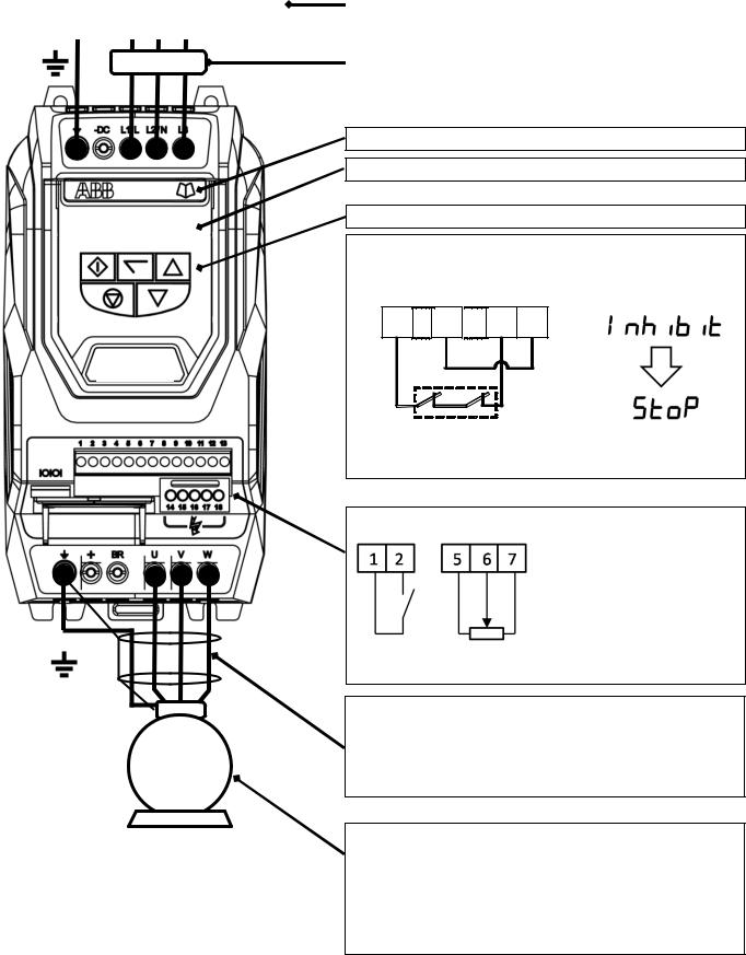
ACS255 – IP20 (600V Variants) |
EASY START-UP GUIDE |
|
|
|
|
|
|
AC Supply Connection |
|
Supply Voltage |
|
3 Phase : Connect L1 L2 L3, PE |
|
500-600 Volts + / - 10% |
|
|
|
|
|
|
|
|
|
Fuses or MCB |
Fuses |
||
Fuse rating recommendation values given on page 59 |
|||
|
|
||
|
|
|
|
Help Card
Display
Keypad Operation can be found in section 6 and 7.2
HARDWARE ENABLE FUNCTION
1 |
9 |
12 |
13 |
 Link the terminals as shown, optionally through switch contacts, to enable the drive.
M
Control Terminals
Based on the factory default parameter settings
Run – Stop 10K Speed Pot
Close the switch to run (enable), open to stop
Motor Cable
o Cable size recommendation values given on page 59. o Observe the maximum permissible motor cable length o For Motor cable lengths > 50 metres, an output filter is
recommended
o Use a screened (shielded cable)
Motor Connection
Check for Star or Delta Connection according to the motor voltage rating (See page 22)
Enter the Motor Nameplate Data into the drive Parameters as follows o Motor Rated Voltage : 9905
o Motor Rated Current : 9906
o Motor Rated Frequency : 9907
o Motor Rated Speed (Optional) : 9908

8
ACS255 – IP66 (600V Variants) |
EASY START-UP GUIDE |
|
|
Fuse rating recommendation values given on page 59
M
AC Supply Connection
500 – 600 Volts + / - 10%
Display
Keypad Operation can be found
In Section 6 and 7.2.
HARDWARE ENABLE
1 |
9 |
12 |
13 |
Link the terminals as shown Above, optionally through switch contacts to enable the drive
Control Terminals
Run / Stop 10K Pot
Close the switch to run (enable)
Open the switch to stop
Motor Cable
Cable size recommendation values given on page 59.
Observe the maximum permissible motor cable length
For Motor cable lengths > 50 metres, an output filter is recommended
Use a screened (shielded) cable. The shield should be bonded to earth at both ends
Motor Connection
Check for Star or Delta Connection according to the motor voltage rating (See page 22).
Enter the Motor Nameplate Data into the drive Parameters as follows
Motor Rated Voltage : 9905
Motor Rated Current : 9906 Motor Rated Frequency : 9907
Motor Rated Speed (Optional) : 9908
9
Declaration of Conformity:
ABB Drives Ltd hereby states that the ACS255 product range conforms to the relevant safety provisions of the following council directives:
2014/30/EU (EMC) and 2014/35/EU (LVD) 2011/65/EU (RoHS)
EN 61800-5-1: 2007 |
Adjustable speed electrical power drive systems. Safety requirements. Electrical, thermal and energy. |
|
|
EN 61800-3 2nd Ed: 2004 |
Adjustable speed electrical power drive systems. EMC requirements and specific test methods |
/ A1:2012 |
|
EN 55011: 2007 |
Limits and Methods of measurement of radio disturbance characteristics of industrial, scientific and |
|
medical (ISM) radio-frequency equipment (EMC) |
EN60529 : 1992 |
Specifications for degrees of protection provided by enclosures |
|
|
STO Function
ACS255 incorporates a hardware STO (Safe Torque Off) Function, designed in accordance with the standards listed below.
Standard |
Classification |
Independent Approval |
EN 61800-5-2:2007 |
Type 2 |
|
|
|
|
EN ISO 13849-1:2006 |
PL “d” |
|
|
|
*TUV |
EN 61508 (Part 1 to 7) |
SIL 2 |
|
|
|
|
EN60204-1 |
Uncontrolled Stop “Category 0” |
|
EN 62061 |
SIL CL 2 |
|
*Note : TUV Approval of the “STO” function is relevant for drives which have a TUV logo applied on the drive rating label.
Electromagnetic Compatibility
It is the responsibility of the installer to ensure that the equipment or system into which the product is incorporated complies with the EMC legislation of the country of use. Within the European Union, equipment into which this product is incorporated must comply with the EMC Directive 2004/108/EC. When using an ACS255 with an internal or optional external filter, compliance with the following EMC Categories, as defined by EN61800-3:2004 can be achieved:
|
Drive Type / Rating |
|
EMC Category – Conducted Emissions |
|
||
|
|
|
|
First Environment Category C1 |
First Environment Category C2 |
Second Environment Category C3 |
|
|
ACS255.. |
|
Use additional External EMC Filter |
|
|
|
|
|
|
|
||
|
|
|
Compliance with EMC standards is dependent on a number of factors including the environment in which the drive is installed, |
|||
|
|
|
motor switching frequency, motor, cable lengths and installation methods adopted. |
|
||
|
Note |
|
For motor cable lengths greater than 100m, an output dv / dt filter must be used, please refer to the (please refer to the |
|||
|
|
http://www.abb.com/ProductGuide/ for further details). |
|
|||
|
|
|
|
|||
|
|
|
Vector Speed and Torque control modes may not operate correctly with long motor cables and output filters. It is recommended to |
|||
|
|
|
operate in V/F mode only for cable lengths exceeding 50m. |
|
||
All rights reserved. No part of this User Guide may be reproduced or transmitted in any form or by any means, electrical or mechanical including photocopying, recording or by any information storage or retrieval system without permission in writing from the publisher.
Copyright ABB Drives Ltd © 2016
The manufacturer accepts no liability for any damage caused during or resulting from transport, receipt of delivery, installation or commissioning. The manufacturer also accepts no liability for damage or consequences resulting from inappropriate, negligent or incorrect installation, incorrect adjustment of the operating parameters of the drive, incorrect matching of the drive to the motor, incorrect installation, unacceptable dust, moisture, corrosive substances, excessive vibration or ambient temperatures outside of the design specification.
Contents of this User Guide are believed to be correct at the time of printing. In the interest of a commitment to a policy of continuous improvement, the manufacturer reserves the right to change the specification of the product or its performance or the contents of the User Guide without notice.
This User Guide is for use with version 2.0 Firmware.
User Guide Revision A
This user guide is the “original instructions” document. All non-English versions are translations of the “original instructions”.
The manufacturer adopts a policy of continuous improvement and while every effort has been made to provide accurate and up to date information, the information contained in this User Guide should be used for guidance purposes only and does not form the part of any contract.
10
2. Safety
What this chapter contains
This chapter contains the safety instructions which you must follow when installing, operating and servicing the drive. If ignored, physical injury or death may follow, or damage may occur to the drive, motor or driven equipment. Read the safety instructions before you work on the unit.
Use of warnings
Warnings caution you about conditions which can result in serious injury or death and/or damage to the equipment and advice on how to avoid the danger. The following warning symbols are used in this manual:
Electricity warning warns of hazards from electricity which can cause physical injury and/or damage to the equipment.
General warning warns about conditions, other than those caused by electricity, which can result in physical injury and/or damage to the equipment.
Safety in installation and maintenance
These warnings are intended for all who work on the drive, motor cable or motor.
Electricity safety
WARNING! Ignoring the instructions can cause physical injury or death, or damage to the equipment.
Only qualified electricians are allowed to install and maintain the drive!
Never work on the drive, motor cable or motor when input power is applied. After disconnecting the input power, always wait for 10 minutes to let the intermediate circuit capacitors discharge before you start working on the drive, motor or motor cable.
Always ensure by measuring with a multimeter (impedance at least 1 Mohm) that:
1.There is no voltage between the drive input phases L1, L2 and L3 and the ground.
2.There is no voltage between terminals + and BR and the ground.
Do not work on the control cables when power is applied to the drive or to the external control circuits. Externally supplied control circuits may carry dangerous voltage even when the input power of the drive is switched off.
Do not make any insulation or voltage withstand tests on the drive.
Be sure the system is properly grounded before applying power. Do not apply AC power before you ensure that all grounding instructions have been followed. Electrical shock can cause serious or fatal injury
Note:
Even when the motor is stopped, dangerous voltage is present at the power circuit terminals L1, L2, L3 and U, V, W and + and BR.

11
General safety
WARNING! Ignoring the following instructions can cause physical injury or death, or damage to the equipment.
The drive is not field repairable. Never attempt to repair a malfunctioning drive; contact your local ABB representative or Authorized Service Centre for replacement.
Make sure that dust from drilling does not enter the drive during the installation. Electrically conductive dust inside the drive may cause damage or lead to malfunction.
Ensure sufficient cooling.
Safety in start-up and operation
These warnings are intended for all who plan the operation, start up or operate the drive.
WARNING! Ignoring the following instructions can cause physical injury or death, or damage to the equipment.
Before adjusting the drive and putting it into service, make sure that the motor and all driven equipment are suitable for operation throughout the speed range provided by the drive. The drive can be adjusted to operate the motor at speeds above and below the speed provided by connecting the motor directly to the power line.
Do not activate automatic fault reset functions if dangerous situations can occur. When activated, these functions reset the drive and resume operation after a fault.
Do not control the motor with an AC contactor or disconnecting device (disconnecting means); use instead the control panel start and stop keys and or external commands (I/O). The maximum allowed number of charging cycles of the DC capacitors (that is, power-ups by applying power) is two per minute.
Note:
When parameter 1103 PRIMARY COMMAND SOURCE MODE is not set to 1 or 2, the stop key on the control panel will not stop the drive. To stop the drive open terminal 2 of the drive control terminals.
12
Please read the IMPORTANT SAFETY INFORMATION below, and all Warning and Caution information elsewhere.
Danger : Indicates a risk of electric shock, which, if not avoided, could result in damage to the equipment and possible injury or death.
Danger : Indicates a potentially hazardous situation other than electrical, which if not avoided, could result in damage to property.
This ACS255 variable speed drive is intended for professional installation and commissioning into complete equipment or systems as part of a fixed installation. If installed incorrectly it may present a safety hazard. The ACS255 uses high voltages and currents, carries a high level of stored electrical energy, and is used to control mechanical plant that may cause injury. Close attention is required to system design and electrical installation to avoid hazards in either normal operation or in the event of equipment malfunction. Only qualified electricians are allowed to install and maintain this product.
System design, installation, commissioning and maintenance must be carried out only by personnel who have the necessary training and experience. They must carefully read this safety information and the instructions in this Guide and follow all information regarding transport, storage, installation and use of the ACS255, including the specified environmental limitations.
Do not perform any flash test or voltage withstand test on the ACS255. Any electrical measurements required should be carried out with the ACS255 disconnected.
Electric shock hazard! Disconnect and ISOLATE the ACS255 before attempting any work on it. High voltages are present at the terminals and within the drive for up to 10 minutes after disconnection of the electrical supply. Always ensure by using a suitable multimeter that no voltage is present on any drive power terminals prior to commencing any work.
Where supply to the drive is through a plug and socket connector, do not disconnect until 10 minutes have elapsed after turning off the supply.
Ensure correct grounding connections and cable selection as per defined by local legislation or codes. The drive may have a leakage current of greater than 3.5mA; furthermore the earth cable must be sufficient to carry the maximum supply fault current which normally will be limited by the fuses. Suitably rated fuses should be fitted in the mains supply to the drive, according to any local legislation or codes.
Do not carry out any work on the drive control cables when power is applied to the drive or to the external control circuits.
The “Safe Torque Off” Function does not prevent high voltages from being present at the drives power terminals.
Within the European Union, all machinery in which this product is used must comply with the Machinery Directive 2006/42/EC, Safety of Machinery. In particular, the machine manufacturer is responsible for providing a main switch and ensuring the electrical equipment complies with EN60204-1.
The level of integrity offered by the ACS255 control input functions – for example stop/start, forward/reverse and maximum speed, is not sufficient for use in safety-critical applications without independent channels of protection. All applications where malfunction could cause injury or loss of life must be subject to a risk assessment and further protection provided where needed.
The driven motor can start at power up if the enable input signal is present.
The STOP function does not remove potentially lethal high voltages. ISOLATE the drive and wait 10 minutes before starting any work on it. Never carry out any work on the Drive, Motor or Motor cable when the input power is still applied.
The ACS255 can be programmed to operate the driven motor at speeds above or below the speed achieved when connecting the motor directly to the mains supply. Obtain confirmation from the manufacturers of the motor and the driven machine about suitability for operation over the intended speed range prior to machine start up.
Do not activate the automatic fault reset function on any systems whereby this may cause a potentially dangerous situation.
IP66 drives provide their own pollution degree 2 environments. IP20 drives must be installed in a pollution degree 2 environment, mounted in a cabinet with IP54 or better.
ACS255s are intended for indoor use only.
When mounting the drive, ensure that sufficient cooling is provided. Do not carry out drilling operations with the drive in place, dust and metal shavings from drilling may lead to damage.
The entry of conductive or flammable foreign bodies should be prevented. Flammable material should not be placed close to the drive
Relative humidity must be less than 95% (non-condensing).
Ensure that the supply voltage, frequency and number of phases correspond to the rating of the ACS255 as delivered.
Never connect the mains power supply to the Output terminals U, V, W.
Do not install any type of automatic switchgear between the drive and the motor
Wherever control cabling is close to power cabling, maintain a minimum separation of 4in. (100 mm) and arrange crossings at 90 degrees
Ensure that all terminals are tightened to the appropriate torque setting
Do not attempt to carry out any repair of the ACS255. In the case of suspected fault or malfunction, contact your local ABB Drives representative for further assistance.

13
3. General Information and Ratings
This chapter contains information about the ACS255 including how to identify the drive.
3.1. Type designation key
The type designation contains information on the specification and configuration of the drive. You find the type designation label attached to the drive. The first digits from the left express the basic configuration, for example ACS255-03U-02A1-6. The explanations of the type designation label selections are described below.
ACS255-03 U-02A1-6+B063+F278
ACS255 product series
1-phase/3 phase
03 = 3-phase input
EMC Filter
E = Filtered
U = Non-Filtered
Output Current Rating
In format xxAy, where xx indicates the integer part and y the fractional part,
For example, 02A1 means 2.1 A.
Input Voltage Range
6 = 500…600VAC
IP66 Enclosure
Input switch assembly
(Speed potentiometer, run/stop and mains disconnect switch)
14
3.2. Drive model numbers – IP20
Mechanical Dimensions and Mounting information is shown from page 15.
Electrical Specifications are shown on page 59.
Model Number |
Power |
Output Current |
Input switch |
Internal DB transistor |
Frame Size |
|
(HP) |
(A) |
assembly |
||||
|
|
|
||||
|
|
|
|
|
|
|
ACS255-03U-02A1-6 |
1 |
2.1 |
No |
Yes |
P2 |
|
|
|
|
|
|
||
ACS255-03U-03A1-6 |
2 |
3.1 |
No |
Yes |
P2 |
|
|
|
|
|
|
||
ACS255-03U-04A1-6 |
3 |
4.1 |
No |
Yes |
P2 |
|
|
|
|
|
|
||
ACS255-03U-06A5-6 |
5 |
6.5 |
No |
Yes |
P2 |
|
|
|
|
|
|
||
ACS255-03U-09A0-6 |
7.5 |
9 |
No |
Yes |
P2 |
|
|
|
|
|
|
||
ACS255-03U-12A0-6 |
10 |
12 |
No |
Yes |
P3 |
|
|
|
|
|
|
||
ACS255-03U-17A0-6 |
15 |
17 |
No |
Yes |
P3 |
|
|
|
|
|
|
||
ACS255-03U-22A0-6 |
20 |
22 |
No |
Yes |
P3 |
|
|
|
|
|
|
3.3. Drive model numbers – IP66
Mechanical Dimensions and Mounting information is shown from page 15.
Electrical Specifications are shown on page 59.
Model Number |
Power |
Output Current |
Input switch |
Internal DB transistor |
Frame Size |
|
(HP) |
(A) |
assembly |
||||
|
|
|
||||
|
|
|
|
|
|
|
ACS255-03U-02A1-6 +B063 |
1 |
2.1 |
No |
Yes |
P2 |
|
|
|
|
|
|
|
|
ACS255-03U-03A1-6 +B063 |
2 |
3.1 |
No |
Yes |
P2 |
|
|
|
|
|
|
|
|
ACS255-03U-04A1-6 +B063 |
3 |
4.1 |
No |
Yes |
P2 |
|
|
|
|
|
|
|
|
ACS255-03U-06A5-6 +B063 |
5 |
6.5 |
No |
Yes |
P2 |
|
|
|
|
|
|
|
|
ACS255-03U-09A0-6 +B063 |
7.5 |
9 |
No |
Yes |
P2 |
|
|
|
|
|
|
|
|
ACS255-03U-12A0-6 +B063 |
10 |
12 |
No |
Yes |
P3 |
|
|
|
|
|
|
|
|
ACS255-03U-17A0-6 +B063 |
15 |
17 |
No |
Yes |
P3 |
|
|
|
|
|
|
|
|
ACS255-03U-02A1-6 +B063 +F278 |
1 |
2.1 |
Yes |
Yes |
P2 |
|
|
|
|
|
|
|
|
ACS255-03U-03A1-6 +B063 +F278 |
2 |
3.1 |
Yes |
Yes |
P2 |
|
|
||||||
|
|
|
|
|
|
|
ACS255-03U-04A1-6 +B063 +F278 |
3 |
4.1 |
Yes |
Yes |
P2 |
|
|
||||||
|
|
|
|
|
|
|
ACS255-03U-06A5-6 +B063 +F278 |
5 |
6.5 |
Yes |
Yes |
P2 |
|
|
||||||
|
|
|
|
|
|
|
ACS255-03U-09A0-6 +B063 +F278 |
7.5 |
9 |
Yes |
Yes |
P2 |
|
|
||||||
|
|
|
|
|
|
|
ACS255-03U-12A0-6 +B063 +F278 |
10 |
12 |
Yes |
Yes |
P3 |
|
|
||||||
|
|
|
|
|
|
|
ACS255-03U-17A0-6 +B063 +F278 |
15 |
17 |
Yes |
Yes |
P3 |
|
|
||||||
|
|
|
|
|
|
15
4. Mechanical Installation
4.1.General
The ACS255 should be mounted in a vertical position only, on a flat, flame resistant, vibration free mounting using the integral mounting holes or DIN Rail clip (Size P2 only).
The ACS255 must be installed in a pollution degree 1 or 2 environment only.
Do not mount flammable material close to the ACS255
Ensure that the minimum cooling air gaps, as detailed in section 4.5 and 4.7 are left clear.
Ensure that the ambient temperature range does not exceed the permissible limits for the ACS255 are given on page 60.
Provide suitable clean, moisture and contaminant free cooling air sufficient to fulfil the cooling requirements of the ACS255.
4.2.Before Installation
Carefully Unpack the ACS255 and check for any signs of damage. Notify the shipper immediately if any exist.
Check the drive rating label to ensure it is of the correct type and power requirements for the application.
To prevent accidental damage always store the ACS255 in its original box until required. Storage should be clean and dry and within the temperature range –40°C to +60°C.
4.3.UL Compliant Installation
Note the following for UL-compliant installation:
For an up to date list of UL compliant products, please refer to UL listing NMMS.E211945.
The drive can be operated within an ambient temperature range as stated in section 11.1.
For IP20 units, installation is required in a pollution degree 1 environment.
For IP66 units, installation in a pollution degree 2 environment is permissible.
UL Listed ring terminals / lugs must be used for all bus bar and grounding connections.
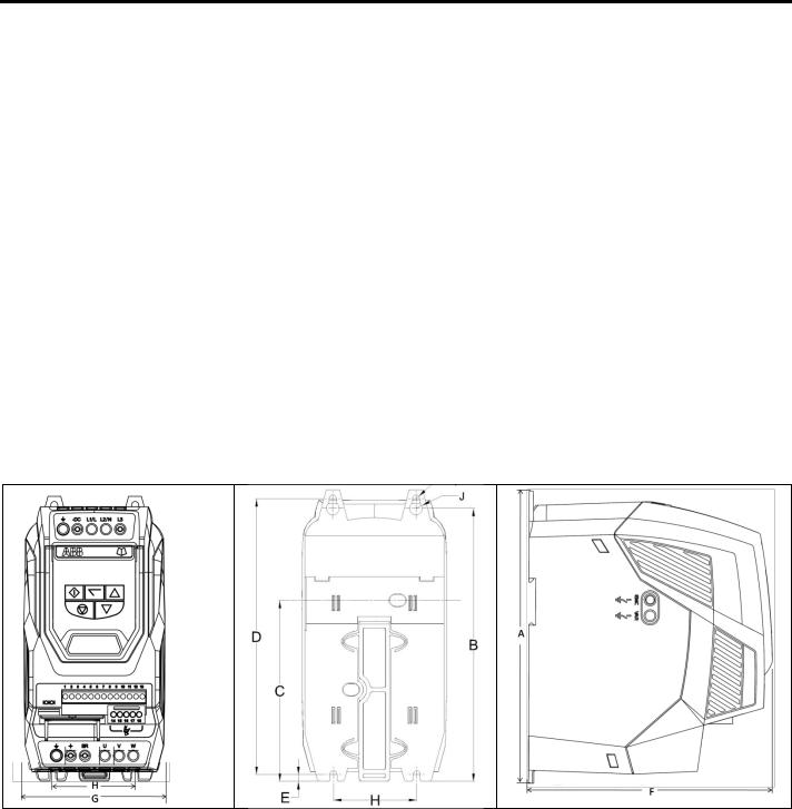
4.4.Mechanical dimensions and weights
4.4.1. IP20 Units
Drive |
|
A |
|
B |
|
C |
|
D |
E |
|
|
F |
|
G |
H |
|
|
I |
J |
|
Weight |
|||||||||
Size |
|
|
|
|
|
|
|
|
|
|
|
|
|
|
|
|
|
|
|
|
|
|
|
|
|
|
|
|
|
|
mm |
in |
mm |
|
in |
mm |
|
in |
mm |
|
in |
mm |
|
in |
mm |
|
in |
mm |
|
in |
mm |
|
in |
mm |
in |
mm |
|
in |
Kg |
Ib |
|
|
|
|
|
|
|
|
|
|
||||||||||||||||||||||
|
|
|
|
|
|
|
|
|
|
|
|
|
|
|
|
|
|
|
|
|
|
|
|
|
|
|
|
|
|
|
2 |
221 |
8.70 |
207 |
|
8.15 |
137 |
|
5.39 |
209 |
|
8.23 |
5.3 |
|
0.21 |
185 |
|
7.28 |
112 |
|
4.41 |
63 |
|
2.48 |
5.5 |
0.22 |
10 |
|
0.39 |
1.8 |
4 |
|
|
|
|
|
|
|
|
|
|
|
|
|
|
|
|
|
|
|
|
|
|
|
|
|
|
|
|
|
|
|
3 |
261 |
10.28 |
246 |
|
9.69 |
- |
|
- |
247 |
|
9.72 |
6 |
|
0.24 |
205 |
|
8.07 |
131 |
|
5.16 |
80 |
|
3.15 |
5.5 |
0.22 |
10 |
|
0.39 |
3.5 |
7.7 |
|
|
|
|
|
|
|
|
|
|
|
|
|
|
|
|
|
|
|
|
|
|
|
|
|
|
|
|
|
|
|
Mounting Bolts
All Frame Sizes : |
4 x M4 |
Tightening Torques
Recommended Control Terminal Torque Settings : All Sizes : 0.8 Nm (7 lb-in)
Recommended Power Terminal Torque Settings :All Sizes : 1 Nm (8.85 lb-in)
16
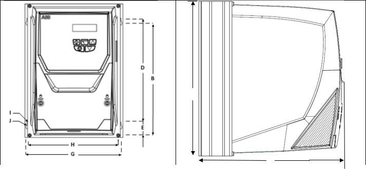
4.4.2. IP66 Units
A
|
|
|
|
|
|
|
|
|
|
|
|
|
|
|
|
|
|
|
|
|
F |
|
|
|
|
|
|
|
|
|
|
|
|
|
|
|
|
|
|
|
|
|
|
|
|
|
|
|
|
|
|
|
|
|
|
|
|
|
|
|
|
|
|
|
|
|
|
|
|
|
|
|
|
|
|
|
|
Drive |
|
A |
|
|
B |
|
D |
|
F |
|
G |
|
H |
|
I |
|
J |
|
Weight |
||||||
Size |
mm |
in |
|
mm |
in |
mm |
|
in |
mm |
|
in |
mm |
|
in |
mm |
|
in |
mm |
in |
mm |
in |
Kg |
|
Ib |
|
2 |
257 |
10.12 |
|
220 |
8.66 |
200 |
|
7.87 |
239 |
|
9.41 |
188 |
|
7.40 |
176 |
|
6.93 |
4.2 |
0.17 |
8.5 |
0.33 |
4.8 |
|
10.6 |
|
3 |
310 |
12.20 |
|
277 |
10.89 |
252 |
|
9.90 |
251 |
|
9.88 |
211 |
|
8.29 |
198 |
|
7.78 |
4.2 |
0.17 |
8.5 |
0.33 |
7.3 |
|
16.1 |
|
Mounting Bolt Sizes |
|
|
|
|
|
|
|
|
|
|
|
|
|
|
|
|
|
|
|
|
|
|
|||
All Frame Sizes |
|
|
4 x M4 |
|
|
|
|
|
|
|
|
|
|
|
|
|
|
|
|
|
|||||
Tightening Torques |
|
|
|
|
|
|
|
|
|
|
|
|
|
|
|
|
|
|
|
|
|
|
|||
Recommended Control Terminal Torque Settings :All Sizes : |
0.8 Nm (7 lb-in) |
|
|
|
|
|
|
|
|
|
|||||||||||||||
Recommended Power Terminal Torque Settings :Frame Size 2 : |
1.2 – 1.5 Nm (10 – 15 lb-in) |
|
|
|
|
|
|
||||||||||||||||||

17
4.5.Guidelines for Enclosure mounting (IP20 Units)
IP20 drives must be installed in a pollution degree 2 environment, mounted in a cabinet with IP54 or better.
Installation should be in a suitable enclosure, according to EN60529 or other relevant local codes or standards.
Enclosures should be made from a thermally conductive material.
Where vented enclosures are used, there should be free space clearance above and below the drive to ensure good air circulation – see the diagram below for minimum free space clearance. Air should be drawn in below the drive and expelled above the drive.
In any environments where the conditions require it, the enclosure must be designed to protect the ACS255 against ingress of airborne dust, corrosive gases or liquids, conductive contaminants (such as condensation, carbon dust, and metallic particles) and sprays or splashing water from all directions.
High moisture, salt or chemical content environments should use a suitably sealed (non-vented) enclosure.
The enclosure design and layout should ensure that the adequate ventilation paths and clearances are left to allow air to circulate through the drive heatsink. Recommend below is the minimum mounting clearance requirements for drives mounted in non-ventilated metallic enclosures.
|
|
Drive |
|
X |
|
Y |
|
Z |
||
|
|
Frame |
Above & |
Either |
Between |
|||||
|
|
Size |
Below |
Side |
||||||
|
|
|
|
|
||||||
|
|
|
mm |
|
in |
mm |
in |
mm |
|
in |
|
|
|
|
|
|
|
|
|
|
|
|
2 |
75 |
|
2.95 |
50 |
1.97 |
46 |
|
1.81 |
|
|
3 |
100 |
|
3.94 |
50 |
1.97 |
52 |
|
2.05 |
|
|
|
Note : |
|
|
|
|
|
|
|
|
Dimension Z assumes that the drives are mounted side- by-side with no clearance.
Typical drive heat losses are 3% of operating load conditions.
Above are guidelines only and the operating ambient temperature of the drive MUST be maintained at all times.
4.6.Mounting the Drive – IP20 Units
IP20 Units are intended for installation within a control cabinet.
When mounting with screws
oUsing the drive as a template, or the dimensions shown above, mark the locations for drilling
oEnsure that when mounting locations are drilled, the dust from drilling does not enter the drive
oMount the drive to the cabinet backplate using suitable M4 mounting screws
oPosition the drive, and tighten the mounting screws securely
When Din Rail Mounting (Frame Size 2 Only)
oLocate the DIN rail mounting slot on the rear of the drive onto the top of the DIN rail first
o Press the bottom of the drive onto the DIN rail until the lower clip attaches to the DIN rail
oIf necessary, use a suitable flat blade screw driver to pull the DIN rail clip down to allow the drive to mount securely on the rail
oTo remove the drive from the DIN rail, use a suitable flat blade screwdriver to pull the release tab downwards, and lift the bottom of the drive away from the rail first
18
4.7.Guidelines for mounting (IP66 Units)
Before mounting the drive, ensure that the chosen location meets the environmental condition requirements for the drive shown in section 11.1.
The drive must be mounted vertically, on a suitable flat surface
The minimum mounting clearances as shown in the table below must be observed
The mounting site and chosen mountings should be sufficient to support the weight of the drives
|
|
|
|
|
|
|
|
|
Drive |
X |
|
|
|
|
|
Y |
|
|
|
|
X |
|
|
Frame |
Above & |
|
|
Either |
|||||||
Y |
|
|
|
|
Size |
Below |
|
|
|
|
Side |
||||||
|
|
|
|
|
|
|
|
|
|
|
|
||||||
|
|
|
|
|
|
|
|
|
|
mm |
|
in |
|
mm |
|
in |
|
|
|
|
|
|
|
|
|
|
|
|
|
|
|
|
|
|
|
|
|
|
|
|
|
|
|
2 |
200 |
|
7.87 |
|
10 |
|
0.39 |
||
|
|
|
|
|
|
|
|
3 |
200 |
|
7.87 |
|
10 |
|
0.39 |
||
|
|
|
|
|
|
|
|
|
Note : |
|
|
|
|
|
|
|
|
|
|
|
|
|
|
|
|
|
Typical drive heat losses are approximately 3% of |
||||||||
|
|
|
|
|
|
|
|
|
operating load conditions. |
|
|
|
|
||||
|
|
|
|
|
|
|
|
|
|
|
|
|
|||||
|
|
|
|
|
|
|
|
|
Above are guidelines only and the operating |
||||||||
|
|
|
|
|
|
|
|
|
|||||||||
|
|
|
|
|
|
|
|
|
ambient temperature of the drive MUST be |
||||||||
|
|
|
|
|
|
|
|
|
maintained at all times. |
|
|
|
|
||||
|
|
|
|
|
|
|
|
|
Cable Gland Sizes |
|
|
|
|
|
|
||
|
|
|
|
|
|
|
|
|
Drive |
Power |
|
|
Motor |
|
Control |
||
|
|
|
|
|
|
|
|
|
Frame |
Cable |
|
|
Cable |
|
Cables |
||
|
|
|
|
|
|
|
|
|
Size |
|
|
|
|
|
|
|
|
|
|
|
|
|
|
|
|
2 |
M25 |
|
|
|
M25 |
|
M20 |
||
|
|
|
|
|
|
|
|
(PG21) |
|
|
(PG21) |
|
(PG13.5) |
||||
|
|
|
X |
|
|
|
|
|
|
|
|
|
|||||
|
|
|
|
|
3 |
M25 |
|
|
|
M25 |
|
M20 |
|||||
|
|
|
|
|
|
|
|
|
|
|
|
||||||
|
|
|
|
|
|
|
|
(PG21) |
|
|
(PG21) |
|
(PG13.5) |
||||
|
|
|
|
|
|
|
|
|
|
|
|
|
|||||
Using the drive as a template, or the dimensions shown above, mark the locations required for drilling
Suitable cable glands to maintain the ingress protection of the drive are required.
Gland holes for power and motor cables are pre-moulded into the drive enclosure, recommended gland sizes are shown above, gland holes for control cables may be cut as required.
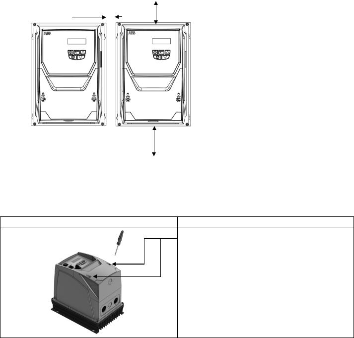
4.8.Removing the Terminal Cover
Frame Sizes 2 & 3
Using a suitable flat blade screwdriver, rotate the two retaining screws indicated until the screw slot is vertical.
4.9. Routine Maintenance
The drive should be included within the scheduled maintenance program so that the installation maintains a suitable operating environment, this should include:
Ambient temperature is at or below that set out in the “Environment” section on page 59.
Heat sink fans freely rotating and dust free.
The Enclosure in which the drive is installed should be free from dust and condensation; furthermore ventilation fans and air filters should be checked for correct air flow.
Checks should also be made on all electrical connections, ensuring screw terminals are correctly torqued; and that power cables have no signs of heat damage.
19
5. Electrical Installation
5.1. Grounding the Drive
This manual is intended as a guide for proper installation. ABB Drives Ltd cannot assume responsibility for the compliance or the non-compliance to any code, national, local or otherwise, for the proper installation of this drive or associated equipment. A hazard of personal injury and/or equipment damage exists if codes are ignored during installation.
This ACS255 contains high voltage capacitors that take time to discharge after removal of the main supply. Before working on the drive, ensure isolation of the main supply from line inputs. Wait ten (10) minutes for the capacitors to discharge to safe voltage levels. Failure to observe this precaution could result in severe bodily injury or loss of life.
Only qualified electrical personnel familiar with the construction and operation of this equipment and the hazards involved should install, adjust, operate, or service this equipment. Read and understand this manual and other applicable manuals in their entirety before proceeding. Failure to observe this precaution could result in severe bodily injury or loss of life.
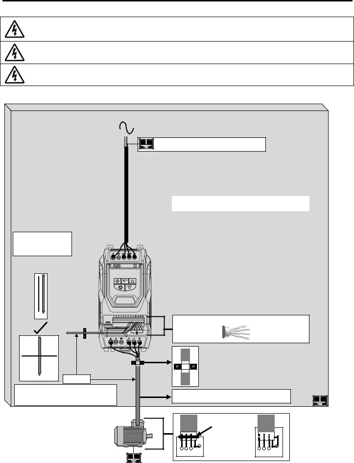
5.1.1. Recommended installation for EMC compliance.
Avoid long parallel runs of motor cables with other cables
X
Metal Back-Panel
Site Ground Bus-Bar bonded to Metal Back-Panel panel which is bonded to main power ground.
|
|
|
|
|
|
|
|
RFI Filter |
|
|
|
||||
Ensure Filter chassis is making metal-metal contact with |
|||||||
Option |
|
|
|||||
|
|
Mounting panel. |
|||||
|
|
|
|
|
|
||
|
|
|
|
|
|
|
|
|
|
|
|
|
|
|
|
|
|
|
|
|
|
|
|
Twisted-Pair shielded cables for analog control and motor
feedback signals.
=/>100mm
Where control cables must cross power cables make sure they are as near to 90 degrees as possible.
Whenever possible use Shielded motor cablesmaintaining shield as far as possible along the cable.
360° bonding EMC cable gland (Best-Practice) (Shield to Motor Chassis)
U V W PE |
U V W PE |
20
5.1.2. Grounding Guidelines
The ground terminal of each ACS255 should be individually connected DIRECTLY to the site ground bus bar (through the filter if installed).
The ACS255 ground connections should not loop from one drive to another, or to, or from any other equipment. Ground loop impedance must confirm to local industrial safety regulations. To meet UL regulations, UL approved ring crimp terminals should be used for all ground wiring connections.
The drive Safety Ground must be connected to system ground. Ground impedance must conform to the requirements of national and local industrial safety regulations and/or electrical codes. The integrity of all ground connections should be checked periodically.
5.1.3. Protective Earth Conductor
The Cross sectional area of the PE Conductor must be at least equal to that of the incoming supply conductor.
5.1.4. Safety Ground 
This is the safety ground for the drive that is required by code. One of these points must be connected to adjacent building steel (girder, joist), a floor ground rod, or bus bar. Grounding points must comply with national and local industrial safety regulations and/or electrical codes.
5.1.5. Motor Ground
The motor ground must be connected to one of the ground terminals on the drive.
5.1.6. Ground Fault Monitoring
As with all inverters, a leakage current to earth can exist. The ACS255 is designed to produce the minimum possible leakage current while complying with worldwide standards. The level of current is affected by motor cable length and type, the effective switching frequency, the earth connections used and the type of RFI filter installed. If a GFCI (Ground Fault Current Interrupter) is to be used, the following conditions apply:
The device must be suitable for protecting equipment with a DC component in the leakage current
Individual GFCI’s should be used for each ACS255
5.1.7. Shield Termination (Cable Screen)
The safety ground terminal provides a grounding point for the motor cable shield. The motor cable shield connected to this terminal (drive end) should also be connected to the motor frame (motor end). Use a shield terminating or EMI clamp to connect the shield to the safety ground terminal.
5.2. Wiring Precautions
Connect the ACS255 according to section 5.9, ensuring that motor terminal box connections are correct. There are two connections in general: Star and Delta. It is essential to ensure that the motor is connected in accordance with the voltage at which it will be operated. For more information, refer to section 5.6 Motor Terminal Box Connections.
Type MC continuous corrugated aluminium armour cable with symmetrical grounds or shielded power cable is recommended for the motor cables if metallic conduit is not used.
The power cables must be rated for 75 °C (167 °F).
5.3.Incoming Power Connection
Power should be connected to L1, L2, and L3. Phase sequence is not important.
For compliance with CE and C Tick EMC requirements, a symmetrical shielded cable is recommended.
For compliance with CSA requirements, transient surge suppression shall be installed on the line side of this equipment and shall be rated 600V (phase to ground), 600V (phase to phase), suitable for overvoltage category III, and shall provide protection for a rated impulse withstand voltage peak of 4 kV or equivalent.
A fixed installation is required according to IEC61800-5-1 with a suitable disconnecting device installed between the ACS255 and the AC Power Source. The disconnecting device must conform to the local safety code / regulations (e.g. within Europe, EN60204-1, Safety of machinery).
The cables should be dimensioned according to any local codes or regulations. Guideline dimensions are given in section 11.2.
Suitable fuses to provide wiring protection of the input power cable should be installed in the incoming supply line, according to the data in section 11.2. The fuses must comply with any local codes or regulations in place. In general, type gG (IEC 60269) or UL type T fuses are suitable; however in some cases type aR fuses may be required. The operating time of the fuses must be below 0.5 seconds.
When the power supply is removed from the drive, a minimum of 30 seconds should be allowed before re-applying the power. A minimum of 5 minutes should be allowed before removing the terminal covers or connection.
The maximum permissible short circuit current at the ACS255 Power terminals as defined in IEC60439-1 is 100kA.
An optional Input Choke is recommended to be installed in the supply line for drives where any of the following conditions occur:-
o The incoming supply impedance is low or the fault level / short circuit current is high.
oIf the transformer kVA rating is more than 10x the kVA rating of the drive or ensure that the per drive source impedance is less than 0.5%
o The supply is prone to dips or brown outs
o An imbalance exists on the supply (3 phase drives)
oThe power supply to the drive is via a busbar and brush gear system (typically overhead Cranes).
In all other installations, an input choke is recommended to ensure protection of the drive against power supply faults.
 Loading...