


 Loading...
—
ABB DRIVES FOR HVAC
ACH580 HVAC control program
Firmware manual
Related documents are listed on page 17.

ACH580
HVAC control program
Firmware manual
 Table of contents
1.Introduction to the manual
2.Start-up, control with I/O and ID run
3.Control panel
4.Settings, I/O and diagnostics on the control panel
5.Default I/O configuration
6.Program features
7.Fault tracing
8.Modbus RTU control through the embedded fieldbus interface (EFB)
9.BACnet MS/TP control through the embedded fieldbus interface (EFB)
10.N2 control through the embedded fieldbus interface (EFB)
11.Fieldbusadapter control through a fieldbus
12.Control chain diagrams
13.Parameters
14.Additional parameter data
3AXD50000027537 Rev E |
2019 ABB Oy. All Rights Reserved. |
EN |
|
EFFECTIVE: 2019-01-11 |
|

Table of contents 5
Table of contents
Part 1
1. Introduction to the manual
Contents of this chapter . . . . . . . . . . . . . . . . . . . . . . . . . . . . . . . . . . . . . . . . . . . . . . . . . . . . . . 15 Applicability . . . . . . . . . . . . . . . . . . . . . . . . . . . . . . . . . . . . . . . . . . . . . . . . . . . . . . . . . . . . . . . 15 Safety instructions . . . . . . . . . . . . . . . . . . . . . . . . . . . . . . . . . . . . . . . . . . . . . . . . . . . . . . . . . . 15 Target audience . . . . . . . . . . . . . . . . . . . . . . . . . . . . . . . . . . . . . . . . . . . . . . . . . . . . . . . . . . . . 16 Purpose of the manual . . . . . . . . . . . . . . . . . . . . . . . . . . . . . . . . . . . . . . . . . . . . . . . . . . . . . . 16 Contents of this manual . . . . . . . . . . . . . . . . . . . . . . . . . . . . . . . . . . . . . . . . . . . . . . . . . . . . . . 16 Related documents . . . . . . . . . . . . . . . . . . . . . . . . . . . . . . . . . . . . . . . . . . . . . . . . . . . . . . . . . 17 Categorization by frame (size) . . . . . . . . . . . . . . . . . . . . . . . . . . . . . . . . . . . . . . . . . . . . . . . . . 19 Cybersecurity disclaimer . . . . . . . . . . . . . . . . . . . . . . . . . . . . . . . . . . . . . . . . . . . . . . . . . . . . . 22
2. Start-up, control with I/O and ID run
Contents of this chapter . . . . . . . . . . . . . . . . . . . . . . . . . . . . . . . . . . . . . . . . . . . . . . . . . . . . . . 25 How to start up the drive . . . . . . . . . . . . . . . . . . . . . . . . . . . . . . . . . . . . . . . . . . . . . . . . . . . . . 26 How to start up the drive using the First start assistant on the Hand-Off-Auto control panel
26
How to control the drive through the I/O interface . . . . . . . . . . . . . . . . . . . . . . . . . . . . . . . . . . 35 How to perform the ID run . . . . . . . . . . . . . . . . . . . . . . . . . . . . . . . . . . . . . . . . . . . . . . . . . . . . 36 ID run procedure . . . . . . . . . . . . . . . . . . . . . . . . . . . . . . . . . . . . . . . . . . . . . . . . . . . . . . . . 37
3. Control panel
Contents of this chapter . . . . . . . . . . . . . . . . . . . . . . . . . . . . . . . . . . . . . . . . . . . . . . . . . . . . . . 45 Removing and reinstalling the control panel . . . . . . . . . . . . . . . . . . . . . . . . . . . . . . . . . . . . . . 45 Layout of the standard Hand-Off-Auto panel control panel . . . . . . . . . . . . . . . . . . . . . . . . . . . 46 Layout of the control panel display . . . . . . . . . . . . . . . . . . . . . . . . . . . . . . . . . . . . . . . . . . . . . 47 Home view displays . . . . . . . . . . . . . . . . . . . . . . . . . . . . . . . . . . . . . . . . . . . . . . . . . . . . . . . . . 49 Keys . . . . . . . . . . . . . . . . . . . . . . . . . . . . . . . . . . . . . . . . . . . . . . . . . . . . . . . . . . . . . . . . . . . . . 51 Key shortcuts . . . . . . . . . . . . . . . . . . . . . . . . . . . . . . . . . . . . . . . . . . . . . . . . . . . . . . . . . . . . . . 52
4. Settings, I/O and diagnostics on the control panel
Contents of this chapter . . . . . . . . . . . . . . . . . . . . . . . . . . . . . . . . . . . . . . . . . . . . . . . . . . . . . . 53 Primary settings . . . . . . . . . . . . . . . . . . . . . . . . . . . . . . . . . . . . . . . . . . . . . . . . . . . . . . . . . . . . 54 HVAC quick setup . . . . . . . . . . . . . . . . . . . . . . . . . . . . . . . . . . . . . . . . . . . . . . . . . . . . . . . 55 Start, stop, reference . . . . . . . . . . . . . . . . . . . . . . . . . . . . . . . . . . . . . . . . . . . . . . . . . . . . . 56 Motor . . . . . . . . . . . . . . . . . . . . . . . . . . . . . . . . . . . . . . . . . . . . . . . . . . . . . . . . . . . . . . . . . 58 Ramps . . . . . . . . . . . . . . . . . . . . . . . . . . . . . . . . . . . . . . . . . . . . . . . . . . . . . . . . . . . . . . . . 60 Limits . . . . . . . . . . . . . . . . . . . . . . . . . . . . . . . . . . . . . . . . . . . . . . . . . . . . . . . . . . . . . . . . . 61 Communication . . . . . . . . . . . . . . . . . . . . . . . . . . . . . . . . . . . . . . . . . . . . . . . . . . . . . . . . . 62 PID control . . . . . . . . . . . . . . . . . . . . . . . . . . . . . . . . . . . . . . . . . . . . . . . . . . . . . . . . . . . . 67 Override . . . . . . . . . . . . . . . . . . . . . . . . . . . . . . . . . . . . . . . . . . . . . . . . . . . . . . . . . . . . . . 69

6 Table of contents
Fault functions . . . . . . . . . . . . . . . . . . . . . . . . . . . . . . . . . . . . . . . . . . . . . . . . . . . . . . . . . 70 Security . . . . . . . . . . . . . . . . . . . . . . . . . . . . . . . . . . . . . . . . . . . . . . . . . . . . . . . . . . . . . . 71 Advanced functions . . . . . . . . . . . . . . . . . . . . . . . . . . . . . . . . . . . . . . . . . . . . . . . . . . . . . 72 Clock, region, display . . . . . . . . . . . . . . . . . . . . . . . . . . . . . . . . . . . . . . . . . . . . . . . . . . . . 74 Reset to defaults . . . . . . . . . . . . . . . . . . . . . . . . . . . . . . . . . . . . . . . . . . . . . . . . . . . . . . . 75
I/O menu . . . . . . . . . . . . . . . . . . . . . . . . . . . . . . . . . . . . . . . . . . . . . . . . . . . . . . . . . . . . . . . . . 77 Diagnostics menu . . . . . . . . . . . . . . . . . . . . . . . . . . . . . . . . . . . . . . . . . . . . . . . . . . . . . . . . . . 78 System info menu . . . . . . . . . . . . . . . . . . . . . . . . . . . . . . . . . . . . . . . . . . . . . . . . . . . . . . . . . . 79 Energy efficiency menu . . . . . . . . . . . . . . . . . . . . . . . . . . . . . . . . . . . . . . . . . . . . . . . . . . . . . 80 Backups menu . . . . . . . . . . . . . . . . . . . . . . . . . . . . . . . . . . . . . . . . . . . . . . . . . . . . . . . . . . . . 82
5. Default I/O configuration |
|
Contents of this chapter . . . . . . . . . . . . . . . . . . . . . . . . . . . . . . . . . . . . . . . . . . . . . . . . . . . . . |
83 |
HVAC default . . . . . . . . . . . . . . . . . . . . . . . . . . . . . . . . . . . . . . . . . . . . . . . . . . . . . . . . . . . . . |
85 |
Default control connections for the HVAC default . . . . . . . . . . . . . . . . . . . . . . . . . . . . . . |
86 |
PID control, single motor . . . . . . . . . . . . . . . . . . . . . . . . . . . . . . . . . . . . . . . . . . . . . . . . . . . . |
87 |
Default control connections for the PID control, single motor . . . . . . . . . . . . . . . . . . . . . |
88 |
6. Program features |
|
What this chapter contains . . . . . . . . . . . . . . . . . . . . . . . . . . . . . . . . . . . . . . . . . . . . . . . . . . . |
89 |
Local control vs. external control . . . . . . . . . . . . . . . . . . . . . . . . . . . . . . . . . . . . . . . . . . . . . . |
89 |
Local control . . . . . . . . . . . . . . . . . . . . . . . . . . . . . . . . . . . . . . . . . . . . . . . . . . . . . . . . . . . |
90 |
External control . . . . . . . . . . . . . . . . . . . . . . . . . . . . . . . . . . . . . . . . . . . . . . . . . . . . . . . . |
91 |
Operating modes of the drive . . . . . . . . . . . . . . . . . . . . . . . . . . . . . . . . . . . . . . . . . . . . . . . . . |
93 |
Drive configuration and programming . . . . . . . . . . . . . . . . . . . . . . . . . . . . . . . . . . . . . . . . . . |
94 |
Configuring via default configurations . . . . . . . . . . . . . . . . . . . . . . . . . . . . . . . . . . . . . . . |
94 |
Configuring via menus . . . . . . . . . . . . . . . . . . . . . . . . . . . . . . . . . . . . . . . . . . . . . . . . . . . |
94 |
Configuring via parameters . . . . . . . . . . . . . . . . . . . . . . . . . . . . . . . . . . . . . . . . . . . . . . . |
94 |
Adaptive programming . . . . . . . . . . . . . . . . . . . . . . . . . . . . . . . . . . . . . . . . . . . . . . . . . . . |
95 |
Control interfaces . . . . . . . . . . . . . . . . . . . . . . . . . . . . . . . . . . . . . . . . . . . . . . . . . . . . . . . . . . |
98 |
Programmable analog inputs . . . . . . . . . . . . . . . . . . . . . . . . . . . . . . . . . . . . . . . . . . . . . . |
98 |
Programmable analog outputs . . . . . . . . . . . . . . . . . . . . . . . . . . . . . . . . . . . . . . . . . . . . . |
98 |
Programmable digital inputs and outputs . . . . . . . . . . . . . . . . . . . . . . . . . . . . . . . . . . . . . |
98 |
Programmable frequency input and output . . . . . . . . . . . . . . . . . . . . . . . . . . . . . . . . . . . |
98 |
Programmable relay outputs . . . . . . . . . . . . . . . . . . . . . . . . . . . . . . . . . . . . . . . . . . . . . . |
99 |
Programmable I/O extensions . . . . . . . . . . . . . . . . . . . . . . . . . . . . . . . . . . . . . . . . . . . . . |
99 |
Fieldbus control . . . . . . . . . . . . . . . . . . . . . . . . . . . . . . . . . . . . . . . . . . . . . . . . . . . . . . . |
100 |
Control of a supply unit (LSU) . . . . . . . . . . . . . . . . . . . . . . . . . . . . . . . . . . . . . . . . . . . . |
100 |
Override . . . . . . . . . . . . . . . . . . . . . . . . . . . . . . . . . . . . . . . . . . . . . . . . . . . . . . . . . . . . . . . . |
102 |
Overview . . . . . . . . . . . . . . . . . . . . . . . . . . . . . . . . . . . . . . . . . . . . . . . . . . . . . . . . . . . . |
102 |
Activating the Override mode . . . . . . . . . . . . . . . . . . . . . . . . . . . . . . . . . . . . . . . . . . . . . |
102 |
Reference for override speed/frequency . . . . . . . . . . . . . . . . . . . . . . . . . . . . . . . . . . . . |
103 |
Override mode features . . . . . . . . . . . . . . . . . . . . . . . . . . . . . . . . . . . . . . . . . . . . . . . . . |
103 |
Application example 1: Override for single override frequency control . . . . . . . . . . . . . |
106 |
Application example 2: Override for PID control . . . . . . . . . . . . . . . . . . . . . . . . . . . . . . |
110 |
Interlocks . . . . . . . . . . . . . . . . . . . . . . . . . . . . . . . . . . . . . . . . . . . . . . . . . . . . . . . . . . . . . . . |
113 |
Overview . . . . . . . . . . . . . . . . . . . . . . . . . . . . . . . . . . . . . . . . . . . . . . . . . . . . . . . . . . . . |
113 |
Application examples of interlocks . . . . . . . . . . . . . . . . . . . . . . . . . . . . . . . . . . . . . . . . . |
114 |
Run permissives . . . . . . . . . . . . . . . . . . . . . . . . . . . . . . . . . . . . . . . . . . . . . . . . . . . . . . . . . . |
117 |

Table of contents 7 |
|
Overview . . . . . . . . . . . . . . . . . . . . . . . . . . . . . . . . . . . . . . . . . . . . . . . . . . . . . . . . . |
. . . . 117 |
Configuration . . . . . . . . . . . . . . . . . . . . . . . . . . . . . . . . . . . . . . . . . . . . . . . . . . . . . . |
. . . . 117 |
Wiring connections . . . . . . . . . . . . . . . . . . . . . . . . . . . . . . . . . . . . . . . . . . . . . . . . . . |
. . . 117 |
Functionality . . . . . . . . . . . . . . . . . . . . . . . . . . . . . . . . . . . . . . . . . . . . . . . . . . . . . . . |
. . . 118 |
Application example 1: Damper end switch . . . . . . . . . . . . . . . . . . . . . . . . . . . . . . . |
. . . 119 |
Application example 2: Valve opening . . . . . . . . . . . . . . . . . . . . . . . . . . . . . . . . . . . |
. . . 119 |
Ramps . . . . . . . . . . . . . . . . . . . . . . . . . . . . . . . . . . . . . . . . . . . . . . . . . . . . . . . . . . . . . . . |
. . . 120 |
Overview . . . . . . . . . . . . . . . . . . . . . . . . . . . . . . . . . . . . . . . . . . . . . . . . . . . . . . . . . . |
. . . 120 |
Application examples . . . . . . . . . . . . . . . . . . . . . . . . . . . . . . . . . . . . . . . . . . . . . . . . |
. . . 122 |
Limits . . . . . . . . . . . . . . . . . . . . . . . . . . . . . . . . . . . . . . . . . . . . . . . . . . . . . . . . . . . . . . . . |
. . . 123 |
Limits overview . . . . . . . . . . . . . . . . . . . . . . . . . . . . . . . . . . . . . . . . . . . . . . . . . . . . . |
. . . 123 |
Application examples . . . . . . . . . . . . . . . . . . . . . . . . . . . . . . . . . . . . . . . . . . . . . . . . |
. . . 123 |
Application control . . . . . . . . . . . . . . . . . . . . . . . . . . . . . . . . . . . . . . . . . . . . . . . . . . . . . . |
. . . 124 |
Automatic fault resets . . . . . . . . . . . . . . . . . . . . . . . . . . . . . . . . . . . . . . . . . . . . . . . . |
. . . 124 |
External events . . . . . . . . . . . . . . . . . . . . . . . . . . . . . . . . . . . . . . . . . . . . . . . . . . . . . |
. . . 124 |
Constant speeds/frequencies . . . . . . . . . . . . . . . . . . . . . . . . . . . . . . . . . . . . . . . . . . |
. . . 124 |
Critical speeds/frequencies . . . . . . . . . . . . . . . . . . . . . . . . . . . . . . . . . . . . . . . . . . . . |
. . . 125 |
Timed functions . . . . . . . . . . . . . . . . . . . . . . . . . . . . . . . . . . . . . . . . . . . . . . . . . . . . . |
. . . 126 |
Motor control . . . . . . . . . . . . . . . . . . . . . . . . . . . . . . . . . . . . . . . . . . . . . . . . . . . . . . . . . . |
. . . 128 |
Speed control mode . . . . . . . . . . . . . . . . . . . . . . . . . . . . . . . . . . . . . . . . . . . . . . . . . |
. . . 128 |
Frequency control mode . . . . . . . . . . . . . . . . . . . . . . . . . . . . . . . . . . . . . . . . . . . . . . |
. . . 128 |
Motor types . . . . . . . . . . . . . . . . . . . . . . . . . . . . . . . . . . . . . . . . . . . . . . . . . . . . . . . . |
. . . 128 |
Motor identification . . . . . . . . . . . . . . . . . . . . . . . . . . . . . . . . . . . . . . . . . . . . . . . . . . |
. . . 128 |
Scalar motor control . . . . . . . . . . . . . . . . . . . . . . . . . . . . . . . . . . . . . . . . . . . . . . . . . |
. . . 128 |
U/f ratio . . . . . . . . . . . . . . . . . . . . . . . . . . . . . . . . . . . . . . . . . . . . . . . . . . . . . . . . . . . |
. . . 129 |
Flux braking . . . . . . . . . . . . . . . . . . . . . . . . . . . . . . . . . . . . . . . . . . . . . . . . . . . . . . . . |
. . . 130 |
Start methods – DC magnetization . . . . . . . . . . . . . . . . . . . . . . . . . . . . . . . . . . . . . . |
. . . 131 |
Switching frequency . . . . . . . . . . . . . . . . . . . . . . . . . . . . . . . . . . . . . . . . . . . . . . . . . |
. . . 133 |
Motor thermal protection . . . . . . . . . . . . . . . . . . . . . . . . . . . . . . . . . . . . . . . . . . . . . . |
. . . 134 |
Motor overload protection . . . . . . . . . . . . . . . . . . . . . . . . . . . . . . . . . . . . . . . . . . . . . |
. . . 140 |
Vector control . . . . . . . . . . . . . . . . . . . . . . . . . . . . . . . . . . . . . . . . . . . . . . . . . . . . . . |
. . . 141 |
Speed control performance figures . . . . . . . . . . . . . . . . . . . . . . . . . . . . . . . . . . . . . . |
. . . 142 |
Floating point control (Motor potentiometer) . . . . . . . . . . . . . . . . . . . . . . . . . . . . . . . |
. . . 142 |
DC voltage control . . . . . . . . . . . . . . . . . . . . . . . . . . . . . . . . . . . . . . . . . . . . . . . . . . . . . . |
. . . 144 |
Overvoltage control . . . . . . . . . . . . . . . . . . . . . . . . . . . . . . . . . . . . . . . . . . . . . . . . . . |
. . . 144 |
Undervoltage control (power loss ride-through) . . . . . . . . . . . . . . . . . . . . . . . . . . . . |
. . . 144 |
Voltage control and trip limits . . . . . . . . . . . . . . . . . . . . . . . . . . . . . . . . . . . . . . . . . . |
. . . 145 |
Brake chopper . . . . . . . . . . . . . . . . . . . . . . . . . . . . . . . . . . . . . . . . . . . . . . . . . . . . . . |
. . . 147 |
Supervisory . . . . . . . . . . . . . . . . . . . . . . . . . . . . . . . . . . . . . . . . . . . . . . . . . . . . . . . . . . . |
. . . 149 |
Signal supervision . . . . . . . . . . . . . . . . . . . . . . . . . . . . . . . . . . . . . . . . . . . . . . . . . . . |
. . . 149 |
Application example 1: Dirty filter . . . . . . . . . . . . . . . . . . . . . . . . . . . . . . . . . . . . . . . |
. . . 149 |
Application example 2: High current . . . . . . . . . . . . . . . . . . . . . . . . . . . . . . . . . . . . . |
. . . 149 |
User load curve . . . . . . . . . . . . . . . . . . . . . . . . . . . . . . . . . . . . . . . . . . . . . . . . . . . . . |
. . . 150 |
Process PID control . . . . . . . . . . . . . . . . . . . . . . . . . . . . . . . . . . . . . . . . . . . . . . . . . . . . . |
. . . 152 |
Multipump/fan control . . . . . . . . . . . . . . . . . . . . . . . . . . . . . . . . . . . . . . . . . . . . . . . . . . . |
. . . 155 |
Single pump and fan control (PFC) . . . . . . . . . . . . . . . . . . . . . . . . . . . . . . . . . . . . . . |
. . . 155 |
Application example 1: Supply fan, Basic speed follower . . . . . . . . . . . . . . . . . . . . . |
. . . 164 |
Application example 2: Supply fan, basic speed follower with interlock and status |
. . . . 166 |
Application example 3: Supply fan, speed follower complete integration . . . . . . . . . |
. . . 168 |
Application example 4: Supply fan, PID control . . . . . . . . . . . . . . . . . . . . . . . . . . . . |
. . . 170 |
Application example 5: Cooling tower fan, speed follower . . . . . . . . . . . . . . . . . . . . |
. . . 172 |

8 Table of contents
Application example 6: Cooling tower, PID . . . . . . . . . . . . . . . . . . . . . . . . . . . . . . . . . . 174 Application example 7: Chilled water pump . . . . . . . . . . . . . . . . . . . . . . . . . . . . . . . . . . 178 Application example 8: Condenser water pump . . . . . . . . . . . . . . . . . . . . . . . . . . . . . . . 180 Energy efficiency . . . . . . . . . . . . . . . . . . . . . . . . . . . . . . . . . . . . . . . . . . . . . . . . . . . . . . . . . 182 Energy optimization . . . . . . . . . . . . . . . . . . . . . . . . . . . . . . . . . . . . . . . . . . . . . . . . . . . . 182 Energy saving calculators . . . . . . . . . . . . . . . . . . . . . . . . . . . . . . . . . . . . . . . . . . . . . . . 182 Load analyzer . . . . . . . . . . . . . . . . . . . . . . . . . . . . . . . . . . . . . . . . . . . . . . . . . . . . . . . . . 183 Managing settings . . . . . . . . . . . . . . . . . . . . . . . . . . . . . . . . . . . . . . . . . . . . . . . . . . . . . . . . 185 User parameter sets . . . . . . . . . . . . . . . . . . . . . . . . . . . . . . . . . . . . . . . . . . . . . . . . . . . . 185 Safety and protections . . . . . . . . . . . . . . . . . . . . . . . . . . . . . . . . . . . . . . . . . . . . . . . . . . . . . 186 Fixed/Standard protections . . . . . . . . . . . . . . . . . . . . . . . . . . . . . . . . . . . . . . . . . . . . . . 186 Programmable protection functions . . . . . . . . . . . . . . . . . . . . . . . . . . . . . . . . . . . . . . . . 186 Emergency stop . . . . . . . . . . . . . . . . . . . . . . . . . . . . . . . . . . . . . . . . . . . . . . . . . . . . . . . 187 Diagnostics . . . . . . . . . . . . . . . . . . . . . . . . . . . . . . . . . . . . . . . . . . . . . . . . . . . . . . . . . . . . . . 189 Diagnostics menu . . . . . . . . . . . . . . . . . . . . . . . . . . . . . . . . . . . . . . . . . . . . . . . . . . . . . . 189 Miscellaneous . . . . . . . . . . . . . . . . . . . . . . . . . . . . . . . . . . . . . . . . . . . . . . . . . . . . . . . . . . . . 190 Backup and restore . . . . . . . . . . . . . . . . . . . . . . . . . . . . . . . . . . . . . . . . . . . . . . . . . . . . 190 Data storage parameters . . . . . . . . . . . . . . . . . . . . . . . . . . . . . . . . . . . . . . . . . . . . . . . . 191 Parameter checksum calculation . . . . . . . . . . . . . . . . . . . . . . . . . . . . . . . . . . . . . . . . . . 191 User lock . . . . . . . . . . . . . . . . . . . . . . . . . . . . . . . . . . . . . . . . . . . . . . . . . . . . . . . . . . . . 193 Sine filter support . . . . . . . . . . . . . . . . . . . . . . . . . . . . . . . . . . . . . . . . . . . . . . . . . . . . . . 193
7. Fault tracing
What this chapter contains . . . . . . . . . . . . . . . . . . . . . . . . . . . . . . . . . . . . . . . . . . . . . . . . . . 195 Safety . . . . . . . . . . . . . . . . . . . . . . . . . . . . . . . . . . . . . . . . . . . . . . . . . . . . . . . . . . . . . . . . . . 195 Indications . . . . . . . . . . . . . . . . . . . . . . . . . . . . . . . . . . . . . . . . . . . . . . . . . . . . . . . . . . . . . . 195 Warnings and faults . . . . . . . . . . . . . . . . . . . . . . . . . . . . . . . . . . . . . . . . . . . . . . . . . . . . 195 Pure events . . . . . . . . . . . . . . . . . . . . . . . . . . . . . . . . . . . . . . . . . . . . . . . . . . . . . . . . . . 196 Editable messages . . . . . . . . . . . . . . . . . . . . . . . . . . . . . . . . . . . . . . . . . . . . . . . . . . . . . 196 Warning/fault history . . . . . . . . . . . . . . . . . . . . . . . . . . . . . . . . . . . . . . . . . . . . . . . . . . . . . . . 196 Event log . . . . . . . . . . . . . . . . . . . . . . . . . . . . . . . . . . . . . . . . . . . . . . . . . . . . . . . . . . . . 196 Viewing warning/fault information . . . . . . . . . . . . . . . . . . . . . . . . . . . . . . . . . . . . . . . . . 197 QR code generation for mobile service application . . . . . . . . . . . . . . . . . . . . . . . . . . . . . . . 197 Warning messages . . . . . . . . . . . . . . . . . . . . . . . . . . . . . . . . . . . . . . . . . . . . . . . . . . . . . . . . 198 Fault messages . . . . . . . . . . . . . . . . . . . . . . . . . . . . . . . . . . . . . . . . . . . . . . . . . . . . . . . . . . 209 Warnings and faults from the LSU supply unit . . . . . . . . . . . . . . . . . . . . . . . . . . . . . . . . . . . 221 Warning messages . . . . . . . . . . . . . . . . . . . . . . . . . . . . . . . . . . . . . . . . . . . . . . . . . . . . 221 Fault messages . . . . . . . . . . . . . . . . . . . . . . . . . . . . . . . . . . . . . . . . . . . . . . . . . . . . . . . 222
8. Modbus RTU control through the embedded fieldbus interface (EFB)
What this chapter contains . . . . . . . . . . . . . . . . . . . . . . . . . . . . . . . . . . . . . . . . . . . . . . . . . . 225 System overview . . . . . . . . . . . . . . . . . . . . . . . . . . . . . . . . . . . . . . . . . . . . . . . . . . . . . . . . . 225 Connecting the drive to the fieldbus . . . . . . . . . . . . . . . . . . . . . . . . . . . . . . . . . . . . . . . . . . . 226 Setting up the embedded fieldbus interface . . . . . . . . . . . . . . . . . . . . . . . . . . . . . . . . . . . . . 228 Setting the drive control parameters . . . . . . . . . . . . . . . . . . . . . . . . . . . . . . . . . . . . . . . . . . 229 Basics of the embedded fieldbus interface . . . . . . . . . . . . . . . . . . . . . . . . . . . . . . . . . . . . . . 231
Control word and Status word . . . . . . . . . . . . . . . . . . . . . . . . . . . . . . . . . . . . . . . . . . . . 232 References . . . . . . . . . . . . . . . . . . . . . . . . . . . . . . . . . . . . . . . . . . . . . . . . . . . . . . . . . . . 232 Actual values . . . . . . . . . . . . . . . . . . . . . . . . . . . . . . . . . . . . . . . . . . . . . . . . . . . . . . . . . 232

Table of contents 9 |
|
Data input/outputs . . . . . . . . . . . . . . . . . . . . . . . . . . . . . . . . . . . . . . . . . . . . . . . . . . . . . . |
232 |
Register addressing . . . . . . . . . . . . . . . . . . . . . . . . . . . . . . . . . . . . . . . . . . . . . . . . . . . . |
232 |
About the control profiles . . . . . . . . . . . . . . . . . . . . . . . . . . . . . . . . . . . . . . . . . . . . . . . . . . . . |
234 |
Control Word . . . . . . . . . . . . . . . . . . . . . . . . . . . . . . . . . . . . . . . . . . . . . . . . . . . . . . . . . . . . . |
235 |
Control Word for the ABB Drives profile . . . . . . . . . . . . . . . . . . . . . . . . . . . . . . . . . . . . . |
235 |
Control Word for the DCU Profile . . . . . . . . . . . . . . . . . . . . . . . . . . . . . . . . . . . . . . . . . . |
236 |
Status Word . . . . . . . . . . . . . . . . . . . . . . . . . . . . . . . . . . . . . . . . . . . . . . . . . . . . . . . . . . . . . . |
239 |
Status Word for the ABB Drives profile . . . . . . . . . . . . . . . . . . . . . . . . . . . . . . . . . . . . . . |
239 |
Status Word for the DCU Profile . . . . . . . . . . . . . . . . . . . . . . . . . . . . . . . . . . . . . . . . . . . |
240 |
State transition diagrams . . . . . . . . . . . . . . . . . . . . . . . . . . . . . . . . . . . . . . . . . . . . . . . . . . . . |
242 |
State transition diagram for the ABB Drives profile . . . . . . . . . . . . . . . . . . . . . . . . . . . . . |
242 |
References . . . . . . . . . . . . . . . . . . . . . . . . . . . . . . . . . . . . . . . . . . . . . . . . . . . . . . . . . . . . . . |
245 |
References for the ABB Drives profile and DCU Profile . . . . . . . . . . . . . . . . . . . . . . . . . |
245 |
Actual values . . . . . . . . . . . . . . . . . . . . . . . . . . . . . . . . . . . . . . . . . . . . . . . . . . . . . . . . . . . . . |
246 |
Actual values for the ABB Drives profile and DCU Profile . . . . . . . . . . . . . . . . . . . . . . . |
246 |
Modbus holding register addresses . . . . . . . . . . . . . . . . . . . . . . . . . . . . . . . . . . . . . . . . . . . . |
247 |
Modbus holding register addresses for the ABB Drives profile and DCU Profile . . . . . . |
247 |
Modbus function codes . . . . . . . . . . . . . . . . . . . . . . . . . . . . . . . . . . . . . . . . . . . . . . . . . . . . . |
248 |
Exception codes . . . . . . . . . . . . . . . . . . . . . . . . . . . . . . . . . . . . . . . . . . . . . . . . . . . . . . . . . . |
249 |
Coils (0xxxx reference set) . . . . . . . . . . . . . . . . . . . . . . . . . . . . . . . . . . . . . . . . . . . . . . . . . . |
250 |
Discrete inputs (1xxxx reference set) . . . . . . . . . . . . . . . . . . . . . . . . . . . . . . . . . . . . . . . . . . |
252 |
Error code registers (holding registers 400090…400100) . . . . . . . . . . . . . . . . . . . . . . . . . . . |
254 |
9. BACnet MS/TP control through the embedded fieldbus interface (EFB)
Contents of this chapter . . . . . . . . . . . . . . . . . . . . . . . . . . . . . . . . . . . . . . . . . . . . . . . . . . . . . 255 BACnet overview . . . . . . . . . . . . . . . . . . . . . . . . . . . . . . . . . . . . . . . . . . . . . . . . . . . . . . . . . . 255 Hardware installation . . . . . . . . . . . . . . . . . . . . . . . . . . . . . . . . . . . . . . . . . . . . . . . . . . . . . . . 256 Connecting devices to a BACnet MS/TP EIA-485 network . . . . . . . . . . . . . . . . . . . . . . . 256 Connecting the drive to the building automation controller . . . . . . . . . . . . . . . . . . . . . . . 256 Starting up BACnet communication through the Primary settings menu . . . . . . . . . . . . . . . . 257 Starting up fieldbus communication with parameters . . . . . . . . . . . . . . . . . . . . . . . . . . . . . . 261 Activating drive control functions . . . . . . . . . . . . . . . . . . . . . . . . . . . . . . . . . . . . . . . . . . . . . . 262 Drive control . . . . . . . . . . . . . . . . . . . . . . . . . . . . . . . . . . . . . . . . . . . . . . . . . . . . . . . . . . 262 Miscellaneous drive control . . . . . . . . . . . . . . . . . . . . . . . . . . . . . . . . . . . . . . . . . . . . . . . 264 Communication fault . . . . . . . . . . . . . . . . . . . . . . . . . . . . . . . . . . . . . . . . . . . . . . . . . . . . 266 Drive feedback . . . . . . . . . . . . . . . . . . . . . . . . . . . . . . . . . . . . . . . . . . . . . . . . . . . . . . . . 266 Parameter setting example . . . . . . . . . . . . . . . . . . . . . . . . . . . . . . . . . . . . . . . . . . . . . . . . . . 269 Frequency control . . . . . . . . . . . . . . . . . . . . . . . . . . . . . . . . . . . . . . . . . . . . . . . . . . . . . . 269 BACnet protocol implementation conformance statement . . . . . . . . . . . . . . . . . . . . . . . . . . 270 Product description: . . . . . . . . . . . . . . . . . . . . . . . . . . . . . . . . . . . . . . . . . . . . . . . . . . . . 270 BACnet standardized device profile (Annex L): . . . . . . . . . . . . . . . . . . . . . . . . . . . . . . . 270 List all BACnet interoperability building blocks supported (Annex K): . . . . . . . . . . . . . . . 270 Segmentation capability: . . . . . . . . . . . . . . . . . . . . . . . . . . . . . . . . . . . . . . . . . . . . . . . . . 271 Standard object types supported: . . . . . . . . . . . . . . . . . . . . . . . . . . . . . . . . . . . . . . . . . . 271 Data link layer options: . . . . . . . . . . . . . . . . . . . . . . . . . . . . . . . . . . . . . . . . . . . . . . . . . . 271 Device address binding: . . . . . . . . . . . . . . . . . . . . . . . . . . . . . . . . . . . . . . . . . . . . . . . . . 271 Networking options: . . . . . . . . . . . . . . . . . . . . . . . . . . . . . . . . . . . . . . . . . . . . . . . . . . . . . 271 Network security options: . . . . . . . . . . . . . . . . . . . . . . . . . . . . . . . . . . . . . . . . . . . . . . . . 272 Character sets supported: . . . . . . . . . . . . . . . . . . . . . . . . . . . . . . . . . . . . . . . . . . . . . . . . 272

10 Table of contents
Object/Property support matrix . . . . . . . . . . . . . . . . . . . . . . . . . . . . . . . . . . . . . . . . . . . . . . . 273 Device object instance summary . . . . . . . . . . . . . . . . . . . . . . . . . . . . . . . . . . . . . . . . . . . . . 273 Binary input object instance summary . . . . . . . . . . . . . . . . . . . . . . . . . . . . . . . . . . . . . . . . . 274 Binary output object instance summary . . . . . . . . . . . . . . . . . . . . . . . . . . . . . . . . . . . . . . . . 275 Binary value object instance summary . . . . . . . . . . . . . . . . . . . . . . . . . . . . . . . . . . . . . . . . . 275 Analog input object instance summary . . . . . . . . . . . . . . . . . . . . . . . . . . . . . . . . . . . . . . . . . 277 Analog output object instance summary . . . . . . . . . . . . . . . . . . . . . . . . . . . . . . . . . . . . . . . 277 Analog value object instance summary . . . . . . . . . . . . . . . . . . . . . . . . . . . . . . . . . . . . . . . . 278 Multistate value object instance summary . . . . . . . . . . . . . . . . . . . . . . . . . . . . . . . . . . . . . . 282 Loop object instance summary . . . . . . . . . . . . . . . . . . . . . . . . . . . . . . . . . . . . . . . . . . . . . . . 284 Mailbox function . . . . . . . . . . . . . . . . . . . . . . . . . . . . . . . . . . . . . . . . . . . . . . . . . . . . . . . . . . 285
10. N2 control through the embedded fieldbus interface (EFB)
Contents of this chapter . . . . . . . . . . . . . . . . . . . . . . . . . . . . . . . . . . . . . . . . . . . . . . . . . . . . 287 N2 overview . . . . . . . . . . . . . . . . . . . . . . . . . . . . . . . . . . . . . . . . . . . . . . . . . . . . . . . . . . . . . 287 Supported features . . . . . . . . . . . . . . . . . . . . . . . . . . . . . . . . . . . . . . . . . . . . . . . . . . . . . 288 Metasys integration . . . . . . . . . . . . . . . . . . . . . . . . . . . . . . . . . . . . . . . . . . . . . . . . . . . . 289 Drive device type . . . . . . . . . . . . . . . . . . . . . . . . . . . . . . . . . . . . . . . . . . . . . . . . . . . . . . 290 Hardware installation . . . . . . . . . . . . . . . . . . . . . . . . . . . . . . . . . . . . . . . . . . . . . . . . . . . . . . 291 Connecting devices to a N2 EIA-485 network . . . . . . . . . . . . . . . . . . . . . . . . . . . . . . . . 291 Connecting the drive to the building automation controller . . . . . . . . . . . . . . . . . . . . . . 291 N2 analog input objects . . . . . . . . . . . . . . . . . . . . . . . . . . . . . . . . . . . . . . . . . . . . . . . . . . . . 291 N2 binary input objects . . . . . . . . . . . . . . . . . . . . . . . . . . . . . . . . . . . . . . . . . . . . . . . . . . . . . 293 N2 analog output objects . . . . . . . . . . . . . . . . . . . . . . . . . . . . . . . . . . . . . . . . . . . . . . . . . . . 294 N2 binary output objects . . . . . . . . . . . . . . . . . . . . . . . . . . . . . . . . . . . . . . . . . . . . . . . . . . . . 295 DDL file for NCU . . . . . . . . . . . . . . . . . . . . . . . . . . . . . . . . . . . . . . . . . . . . . . . . . . . . . . . . . . 297
11. Fieldbus control through a fieldbus adapter
What this chapter contains . . . . . . . . . . . . . . . . . . . . . . . . . . . . . . . . . . . . . . . . . . . . . . . . . . 301 System overview . . . . . . . . . . . . . . . . . . . . . . . . . . . . . . . . . . . . . . . . . . . . . . . . . . . . . . . . . 301 Basics of the fieldbus control interface . . . . . . . . . . . . . . . . . . . . . . . . . . . . . . . . . . . . . . . . . 303 Control word and Status word . . . . . . . . . . . . . . . . . . . . . . . . . . . . . . . . . . . . . . . . . . . . 304 References . . . . . . . . . . . . . . . . . . . . . . . . . . . . . . . . . . . . . . . . . . . . . . . . . . . . . . . . . . . 305 Actual values . . . . . . . . . . . . . . . . . . . . . . . . . . . . . . . . . . . . . . . . . . . . . . . . . . . . . . . . . 306 Contents of the fieldbus Control word (ABB Drives profile) . . . . . . . . . . . . . . . . . . . . . . 307 Contents of the fieldbus Status word (ABB Drives profile) . . . . . . . . . . . . . . . . . . . . . . . 308 The state diagram . . . . . . . . . . . . . . . . . . . . . . . . . . . . . . . . . . . . . . . . . . . . . . . . . . . . . 309 Setting up the drive for fieldbus control . . . . . . . . . . . . . . . . . . . . . . . . . . . . . . . . . . . . . . . . 310 Parameter setting example: FPBA (PROFIBUS DP) with ABB Drives profile . . . . . . . . 311 Parameter setting example: FPBA (PROFIBUS DP) with PROFIdrive profile . . . . . . . . 313 Automatic drive configuration for fieldbus control . . . . . . . . . . . . . . . . . . . . . . . . . . . . . . . . . 315
12. Control chain diagrams
Contents of this chapter . . . . . . . . . . . . . . . . . . . . . . . . . . . . . . . . . . . . . . . . . . . . . . . . . . . . 319 Frequency reference selection . . . . . . . . . . . . . . . . . . . . . . . . . . . . . . . . . . . . . . . . . . . . . . . 320 Frequency reference modification . . . . . . . . . . . . . . . . . . . . . . . . . . . . . . . . . . . . . . . . . . . . 321 Speed reference source selection I . . . . . . . . . . . . . . . . . . . . . . . . . . . . . . . . . . . . . . . . . . . 322 Speed reference source selection II . . . . . . . . . . . . . . . . . . . . . . . . . . . . . . . . . . . . . . . . . . . 323
Table of contents 11
Speed reference ramping and shaping . . . . . . . . . . . . . . . . . . . . . . . . . . . . . . . . . . . . . . . . . 324 Speed error calculation . . . . . . . . . . . . . . . . . . . . . . . . . . . . . . . . . . . . . . . . . . . . . . . . . . . . . 325 Speed feedback . . . . . . . . . . . . . . . . . . . . . . . . . . . . . . . . . . . . . . . . . . . . . . . . . . . . . . . . . . . 326 Speed controller . . . . . . . . . . . . . . . . . . . . . . . . . . . . . . . . . . . . . . . . . . . . . . . . . . . . . . . . . . 327 Torque limitation . . . . . . . . . . . . . . . . . . . . . . . . . . . . . . . . . . . . . . . . . . . . . . . . . . . . . . . . . . 328 PID flow calculation . . . . . . . . . . . . . . . . . . . . . . . . . . . . . . . . . . . . . . . . . . . . . . . . . . . . . . . . 329 PID setpoint compensation . . . . . . . . . . . . . . . . . . . . . . . . . . . . . . . . . . . . . . . . . . . . . . . . . . 330 Process PID setpoint and feedback source selection . . . . . . . . . . . . . . . . . . . . . . . . . . . . . . 331 Process PID controller . . . . . . . . . . . . . . . . . . . . . . . . . . . . . . . . . . . . . . . . . . . . . . . . . . . . . . 332 External PID setpoint and feedback source selection . . . . . . . . . . . . . . . . . . . . . . . . . . . . . . 333 External PID controller . . . . . . . . . . . . . . . . . . . . . . . . . . . . . . . . . . . . . . . . . . . . . . . . . . . . . . 334 Direction lock . . . . . . . . . . . . . . . . . . . . . . . . . . . . . . . . . . . . . . . . . . . . . . . . . . . . . . . . . . . . . 335 Override . . . . . . . . . . . . . . . . . . . . . . . . . . . . . . . . . . . . . . . . . . . . . . . . . . . . . . . . . . . . . . . . . 336
Part 2 Parameters |
|
|
13. Parameters |
|
|
What this chapter contains . . . . . . . . . . . . . . . . . . . . . . . . . . . . . . . . . . . . . . . . . . . . . . . . . . |
339 |
|
Terms and abbreviations . . . . . . . . . . . . . . . . . . . . . . . . . . . . . . . . . . . . . . . . . . . . . . . . . . . . |
340 |
|
Summary of parameter groups . . . . . . . . . . . . . . . . . . . . . . . . . . . . . . . . . . . . . . . . . . . . . . . |
341 |
|
Parameter listing . . . . . . . . . . . . . . . . . . . . . . . . . . . . . . . . . . . . . . . . . . . . . . . . . . . . . . . . . . |
343 |
|
01 |
Actual values . . . . . . . . . . . . . . . . . . . . . . . . . . . . . . . . . . . . . . . . . . . . . . . . . . . . . . . |
343 |
03 |
Input references . . . . . . . . . . . . . . . . . . . . . . . . . . . . . . . . . . . . . . . . . . . . . . . . . . . . . |
347 |
04 |
Warnings and faults . . . . . . . . . . . . . . . . . . . . . . . . . . . . . . . . . . . . . . . . . . . . . . . . . . |
348 |
05 |
Diagnostics . . . . . . . . . . . . . . . . . . . . . . . . . . . . . . . . . . . . . . . . . . . . . . . . . . . . . . . . . |
349 |
06 |
Control and status words . . . . . . . . . . . . . . . . . . . . . . . . . . . . . . . . . . . . . . . . . . . . . . |
352 |
07 |
System info . . . . . . . . . . . . . . . . . . . . . . . . . . . . . . . . . . . . . . . . . . . . . . . . . . . . . . . . |
361 |
10 |
Standard DI, RO . . . . . . . . . . . . . . . . . . . . . . . . . . . . . . . . . . . . . . . . . . . . . . . . . . . . . |
363 |
11 |
Standard DIO, FI, FO . . . . . . . . . . . . . . . . . . . . . . . . . . . . . . . . . . . . . . . . . . . . . . . . . |
374 |
12 |
Standard AI . . . . . . . . . . . . . . . . . . . . . . . . . . . . . . . . . . . . . . . . . . . . . . . . . . . . . . . . |
375 |
13 |
Standard AO . . . . . . . . . . . . . . . . . . . . . . . . . . . . . . . . . . . . . . . . . . . . . . . . . . . . . . . |
380 |
15 |
I/O extension module . . . . . . . . . . . . . . . . . . . . . . . . . . . . . . . . . . . . . . . . . . . . . . . . . |
386 |
19 |
Operation mode . . . . . . . . . . . . . . . . . . . . . . . . . . . . . . . . . . . . . . . . . . . . . . . . . . . . . |
395 |
20 |
Start/stop/direction . . . . . . . . . . . . . . . . . . . . . . . . . . . . . . . . . . . . . . . . . . . . . . . . . . . |
396 |
21 |
Start/stop mode . . . . . . . . . . . . . . . . . . . . . . . . . . . . . . . . . . . . . . . . . . . . . . . . . . . . . |
405 |
22 |
Speed reference selection . . . . . . . . . . . . . . . . . . . . . . . . . . . . . . . . . . . . . . . . . . . . . |
413 |
23 |
Speed reference ramp . . . . . . . . . . . . . . . . . . . . . . . . . . . . . . . . . . . . . . . . . . . . . . . . |
423 |
24 |
Speed reference conditioning . . . . . . . . . . . . . . . . . . . . . . . . . . . . . . . . . . . . . . . . . . |
425 |
25 |
Speed control . . . . . . . . . . . . . . . . . . . . . . . . . . . . . . . . . . . . . . . . . . . . . . . . . . . . . . . |
426 |
28 |
Frequency reference chain . . . . . . . . . . . . . . . . . . . . . . . . . . . . . . . . . . . . . . . . . . . . |
431 |
30 |
Limits . . . . . . . . . . . . . . . . . . . . . . . . . . . . . . . . . . . . . . . . . . . . . . . . . . . . . . . . . . . . . |
441 |
31 |
Fault functions . . . . . . . . . . . . . . . . . . . . . . . . . . . . . . . . . . . . . . . . . . . . . . . . . . . . . . |
452 |
32 |
Supervision . . . . . . . . . . . . . . . . . . . . . . . . . . . . . . . . . . . . . . . . . . . . . . . . . . . . . . . . |
462 |
34 |
Timed functions . . . . . . . . . . . . . . . . . . . . . . . . . . . . . . . . . . . . . . . . . . . . . . . . . . . . . |
469 |
35 |
Motor thermal protection . . . . . . . . . . . . . . . . . . . . . . . . . . . . . . . . . . . . . . . . . . . . . . |
477 |
36 |
Load analyzer . . . . . . . . . . . . . . . . . . . . . . . . . . . . . . . . . . . . . . . . . . . . . . . . . . . . . . . |
488 |
37 |
User load curve . . . . . . . . . . . . . . . . . . . . . . . . . . . . . . . . . . . . . . . . . . . . . . . . . . . . . |
491 |
40 |
Process PID set 1 . . . . . . . . . . . . . . . . . . . . . . . . . . . . . . . . . . . . . . . . . . . . . . . . . . . |
494 |
41 |
Process PID set 2 . . . . . . . . . . . . . . . . . . . . . . . . . . . . . . . . . . . . . . . . . . . . . . . . . . . |
511 |
43 |
Brake chopper . . . . . . . . . . . . . . . . . . . . . . . . . . . . . . . . . . . . . . . . . . . . . . . . . . . . . . |
513 |

12 Table of contents |
|
|
45 |
Energy efficiency . . . . . . . . . . . . . . . . . . . . . . . . . . . . . . . . . . . . . . . . . . . . . . . . . . . . |
515 |
46 |
Monitoring/scaling settings . . . . . . . . . . . . . . . . . . . . . . . . . . . . . . . . . . . . . . . . . . . . |
520 |
47 |
Data storage . . . . . . . . . . . . . . . . . . . . . . . . . . . . . . . . . . . . . . . . . . . . . . . . . . . . . . . |
523 |
49 |
Panel port communication . . . . . . . . . . . . . . . . . . . . . . . . . . . . . . . . . . . . . . . . . . . . . |
524 |
50 |
Fieldbus adapter (FBA) . . . . . . . . . . . . . . . . . . . . . . . . . . . . . . . . . . . . . . . . . . . . . . . |
525 |
51 |
FBA A settings . . . . . . . . . . . . . . . . . . . . . . . . . . . . . . . . . . . . . . . . . . . . . . . . . . . . . |
529 |
52 |
FBA A data in . . . . . . . . . . . . . . . . . . . . . . . . . . . . . . . . . . . . . . . . . . . . . . . . . . . . . . |
530 |
53 |
FBA A data out . . . . . . . . . . . . . . . . . . . . . . . . . . . . . . . . . . . . . . . . . . . . . . . . . . . . . |
531 |
58 |
Embedded fieldbus . . . . . . . . . . . . . . . . . . . . . . . . . . . . . . . . . . . . . . . . . . . . . . . . . . |
531 |
60 |
DDCS communication . . . . . . . . . . . . . . . . . . . . . . . . . . . . . . . . . . . . . . . . . . . . . . . . |
540 |
61 |
D2D and DDCS transmit data . . . . . . . . . . . . . . . . . . . . . . . . . . . . . . . . . . . . . . . . . . |
540 |
62 |
D2D and DDCS receive data . . . . . . . . . . . . . . . . . . . . . . . . . . . . . . . . . . . . . . . . . . |
541 |
70 |
Override . . . . . . . . . . . . . . . . . . . . . . . . . . . . . . . . . . . . . . . . . . . . . . . . . . . . . . . . . . |
541 |
71 |
External PID1 . . . . . . . . . . . . . . . . . . . . . . . . . . . . . . . . . . . . . . . . . . . . . . . . . . . . . . |
546 |
72 |
External PID2 . . . . . . . . . . . . . . . . . . . . . . . . . . . . . . . . . . . . . . . . . . . . . . . . . . . . . . |
547 |
73 |
External PID3 . . . . . . . . . . . . . . . . . . . . . . . . . . . . . . . . . . . . . . . . . . . . . . . . . . . . . . |
549 |
74 |
External PID4 . . . . . . . . . . . . . . . . . . . . . . . . . . . . . . . . . . . . . . . . . . . . . . . . . . . . . . |
551 |
76 |
PFC configuration . . . . . . . . . . . . . . . . . . . . . . . . . . . . . . . . . . . . . . . . . . . . . . . . . . . |
554 |
77 |
PFC maintenance and monitoring . . . . . . . . . . . . . . . . . . . . . . . . . . . . . . . . . . . . . . . |
561 |
80 |
Flow calculation and protection . . . . . . . . . . . . . . . . . . . . . . . . . . . . . . . . . . . . . . . . . |
562 |
94 |
LSU control . . . . . . . . . . . . . . . . . . . . . . . . . . . . . . . . . . . . . . . . . . . . . . . . . . . . . . . . |
563 |
95 |
HW configuration . . . . . . . . . . . . . . . . . . . . . . . . . . . . . . . . . . . . . . . . . . . . . . . . . . . . |
564 |
96 |
System . . . . . . . . . . . . . . . . . . . . . . . . . . . . . . . . . . . . . . . . . . . . . . . . . . . . . . . . . . . |
567 |
97 |
Motor control . . . . . . . . . . . . . . . . . . . . . . . . . . . . . . . . . . . . . . . . . . . . . . . . . . . . . . . |
577 |
98 |
User motor parameters . . . . . . . . . . . . . . . . . . . . . . . . . . . . . . . . . . . . . . . . . . . . . . . |
581 |
99 |
Motor data . . . . . . . . . . . . . . . . . . . . . . . . . . . . . . . . . . . . . . . . . . . . . . . . . . . . . . . . . |
583 |
Differences in the default values between 50 Hz and 60 Hz supply frequency settings . . . |
589 |
|
14. Additional parameter data
What this chapter contains . . . . . . . . . . . . . . . . . . . . . . . . . . . . . . . . . . . . . . . . . . . . . . . . . . 591 Terms and abbreviations . . . . . . . . . . . . . . . . . . . . . . . . . . . . . . . . . . . . . . . . . . . . . . . . . . . 591 Fieldbus addresses . . . . . . . . . . . . . . . . . . . . . . . . . . . . . . . . . . . . . . . . . . . . . . . . . . . . . . . 592 Parameter groups 1…9 . . . . . . . . . . . . . . . . . . . . . . . . . . . . . . . . . . . . . . . . . . . . . . . . . . . . 593 Parameter groups 10…99 . . . . . . . . . . . . . . . . . . . . . . . . . . . . . . . . . . . . . . . . . . . . . . . . . . 597
Further information
Product and service inquiries . . . . . . . . . . . . . . . . . . . . . . . . . . . . . . . . . . . . . . . . . . . . . . . . 631 Product training . . . . . . . . . . . . . . . . . . . . . . . . . . . . . . . . . . . . . . . . . . . . . . . . . . . . . . . . . . 631 Providing feedback on ABB Drives manuals . . . . . . . . . . . . . . . . . . . . . . . . . . . . . . . . . . . . 631 Document library on the Internet . . . . . . . . . . . . . . . . . . . . . . . . . . . . . . . . . . . . . . . . . . . . . 631

ACH580
HVAC control program
Firmware manual Part 1
 Table of contents
1.Introduction to the manual
2.Start-up, control with I/O and ID run
3.Control panel
4.Settings, I/O and diagnostics on the control panel
5.Default I/O configuration
6.Program features
7.Fault tracing
8.Modbus RTU control through the embedded fieldbus interface (EFB)
9.BACnet MS/TP control through the embedded fieldbus interface (EFB)
10.N2 control through the embedded fieldbus interface (EFB)
11.Fieldbusadapter control through a fieldbus
12.Control chain diagrams
Corresponds to
3AXD50000209811 Rev B 2019 ABB Oy. All Rights Reserved. EN
EFFECTIVE: 2019-01-11

Introduction to the manual 15
1 1
Introduction to the manual
Contents of this chapter
The chapter describes applicability, target audience and purpose of this manual. It also describes the contents of this manual and refers to a list of related manuals for more information.
Applicability
The manual applies to the ACH580 HVAC control program (version 2.08).
To check the firmware version of the control program in use, see system information (select Menu > System info > Drive) or parameter 07.05 Firmware version on the control panel.
For ACH580-31, to check the ISU firmware version in use, select Menu > Exit > Options > Select drive > QCON-21 and then select Menu > System info > Drive, or see parameters 07.106 LSU loading package name and 07.107 LSU loading package version on the control panel.
Safety instructions
Follow all safety instructions.
•Read the complete safety instructions in the Hardware manual of the drive before you install, commission, or use the drive.
•Read the firmware function-specific warnings and notes before changing parameter values. These warnings and notes are included in the parameter descriptions presented in chapter Parameters on page 195.

16 Introduction to the manual
1 Target audience
The reader is expected to know the fundamentals of electricity, wiring, electrical components and electrical schematic symbols.
The manual is written for readers worldwide. Both SI and imperial units are shown. Special US instructions for installations in the United States are given.
Purpose of the manual
This manual provides information needed for designing, commissioning, or operating the drive system.
Contents of this manual
The manual consists of the following chapters:
•Introduction to the manual (this chapter) describes applicability, target audience, purpose and contents of this manual. At the end, it lists terms and abbreviations.
•Start-up, control with I/O and ID run (page 25) describes how to start up the drive as well as how to start, change the direction of the motor rotation and adjust the motor speed through the I/O interface.
•Control panel (page 45) contains instructions for removing and reinstalling the assistant control panel and briefly describes its display, keys and key shortcuts.
•Settings, I/O and diagnostics on the control panel (page 53) describes the simplified settings and diagnostic functions provided on the assistant control panel.
•Default I/O configuration (page 83) contains the connection diagram of the HVAC default configuration together with a connection diagram. The predefined default configuration will save the user time when configuring the drive.
•Program features (page 89) describes program features with lists of related user settings, actual signals, and fault and warning messages.
•Modbus RTU control through the embedded fieldbus interface (EFB) (page 225) describes the communication to and from a fieldbus network using the drive embedded fieldbus interface with the Modbus RTU protocol.
•BACnet MS/TP control through the embedded fieldbus interface (EFB) (page 255) describes the communication to and from a fieldbus network using the drive embedded fieldbus interface with the BACnet MS/TP protocol.
•N2 control through the embedded fieldbus interface (EFB) (page 287) describes the communication to and from a fieldbus network using the drive embedded fieldbus interface with the BACnet MS/TP protocol.
•Fieldbus control through a fieldbus adapter (page 301) describes the communication to and from a fieldbus network using an optional fieldbus adapter module.

Introduction to the manual 17
•Fault tracing (page 195) lists the warning and fault messages with possible causes and remedies.
•Control chain diagrams (page 319) describes the parameter structure within the drive.
•Parameters (page 195) describes the parameters used to program the drive.
•Additional parameter data (page 591) contains further information on the parameters.
•Further information (inside of the back cover, page 631) describes how to make product and service inquiries, get information on product training, provide feedback on ABB Drives manuals and find documents on the Internet.
1 |
Related documents
You can find manuals and other product documents in PDF format on the Internet. See section Document library on the Internet on the inside of the back cover. For manuals not available in the Document library, contact your local ABB representative
Drive manuals and guides |
Code (English) |
|
ACH580 HVAC control program firmware manual |
3AXD50000027537 |
|
ACH580 HVAC control program firmware manual, Part 1 |
3AXD50000209811 |
|
ACH580 HVAC control program firmware manual, Part 2 |
3AXD50000209828 |
|
Parameters |
|
|
ACH580-01 (0.75 to 250 kW, 1 to 350 hp) hardware |
3AXD50000044839 |
|
manual |
|
|
ACH580-31 hardware manual |
3AXD50000037066 |
|
ACH580-01 quick installation and start-up guide for |
3AXD50000044861 |
|
frames R1 to R5 |
|
|
ACH580-01 quick installation and start-up guide for |
3AXD50000036602 |
|
frames R6 to R9 |
|
|
ACH580 Installation, Operation, and Maintenance |
3AXD50000049127 |
|
Manual (I, O & M) (US only) |
|
|
Quick start-up guide for ACH580 HVAC control |
3AXD50000047658 |
|
program |
|
|
ACH580-31 quick installation guide |
3AXD50000048001 |
|
Adaptive programming application guide |
3AXD50000028574 |
|
ACX-AP-x assistant control panels user’s manual |
3AUA0000085685 |
|
Option manuals and guides |
|
|
BACnet Protocol Implementation Conformance |
3AXD10000387059 |
|
Statement (PICS) |
|
|
CDPI-01 communication adapter module user's |
3AXD50000009929 |
|
manual |
|
|
FBIP-21 BACnet/IP adapter module user's manual |
3AXD50000028468 |
|
FCAN-01 CANopen adapter module user's manual |
3AFE68615500 |
|
FCNA-01 ControlNet adapter module user's manual |
3AUA0000141650 |
|
FDNA-01 DeviceNet™ adapter module user's manual |
3AFE68573360 |
|
FECA-01 EtherCAT adapter module user's manual |
3AUA0000068940 |
|
|
|
|

18 Introduction to the manual
1 |
FEIP-21 Ethernet/IP adapter module user’s manual |
3AXD50000158621 |
FENA-01/-11/-21 Ethernet adapter module user's |
3AUA0000093568 |
manual |
|
FEPL-02 Ethernet POWERLINK adapter module user's 3AUA0000123527 manual
FLON-01 LONWORKS® adapter module user’s manual |
3AUA0000041017 |
FMBA-01 Modbus adapter module user’s manual |
3AFE68586704 |
FMBT-21 Modbus/TCP adapter module user’s manual |
3AXD50000158607 |
FPBA-01 PROFIBUS DP adapter module user's |
3AFE68573271 |
manual |
|
FPNO-21 PROFINET adapter module user’s manual |
3AXD50000158614 |
FSCA-01 RS-485 adapter module user's manual |
3AUA0000109533 |
Flange mounting kit installation supplement |
3AXD50000019100 |
Flange mounting kit quick installation guide for |
3AXD50000119172 |
ACX580-01 frames R1 to R3 |
|
Flange mounting kit quick installation guide for |
3AXD50000287093 |
ACS580-01, ACH580-01 and ACQ580-01 frames R4 to |
|
R5 |
|
Flange mounting kit quick installation guide for |
3AXD50000019099 |
ACS880-01 and ACX580-01 frames R6 to R9 |
|
Flange mounting kit quick installation guide for |
3AXD50000181506 |
ACS880-11, ACS880-31, ACH580-31 and ACQ580- |
|
31 frame R3 |
|
Flange mounting kit quick installation guide for |
3AXD50000133611 |
ACS880-11, ACS880-31, ACH580-31 and ACQ580- |
|
31 frames R6 and R8 |
|
ACS580, ACH580 and ACQ580 drive module frames |
3AXD50000210305 |
R3, R5 to R9 for cabinet installation (options +P940 |
|
and +P944 supplement |
|
Main switch and EMC C1 filter options (+F278, +F316, |
3AXD50000155132 |
+E223) installation supplement for ACS580-01, |
|
ACH580-01 and ACH580-01 frames R1 to R5 |
|
Common mode filter kit for frames R7 and R8 (option |
3XD50000015179 |
+E208) installation guide |
|
UK gland plate (+H358) installation guide for ACS880- |
3AXD50000110711 |
11, ACS880-31, ACH580-31and ACQ580-31 |
|
UL Type 12 hood quick installation guide for ACS580- |
3AXD50000196067 |
01, ACH580-01 and ACQ580-01 frames R1 to R9 |
|
Tool and maintenance manuals and guides |
|
Drive composer PC tool user's manual |
3AUA0000094606 |
Converter module capacitor reforming instructions |
3BFE64059629 |
NETA-21 remote monitoring tool user's manual |
3AUA0000096939 |
NETA-21 remote monitoring tool installation and start- |
3AUA0000096881 |
up guide |
|

Introduction to the manual 19
1 |
ACH580-01 manuals
Categorization by frame (size)
The ACH580 is manufactured in several frames (frame sizes), which are denoted as RN, where N is an integer. Some information which only concern certain frames are marked with the symbol of the frame (RN).
The frame is marked on the type designation label attached to the drive, see chapter
Operation principle and hardware description, section Type designation label in the Hardware manual of the drive.

|
20 Introduction to the manual |
|
1 |
Terms and abbreviations |
|
|
Term/abbreviation |
Explanation |
|
ACX-AP-x |
Assistant control panel, advanced operator keypad for communication |
|
|
with the drive. |
|
|
The ACH580 supports the Hand-Off-Auto panels ACH-AP-H and ACH- |
|
|
AP-W (with a Bluetooth interface). |
|
AI |
Analog input; interface for analog input signals |
|
AO |
Analog output; interface for analog output signals |
|
BACnet™ |
BACnet™ is a registered trademark of American Society of Heating, |
|
|
Refrigerating and Air-Conditioning Engineers (ASHRAE). |
|
BAS |
Building automation system |
|
BMS |
Building management system |
|
Brake chopper |
Conducts the surplus energy from the intermediate circuit of the drive to |
|
|
the brake resistor when necessary. The chopper operates when the DC |
|
|
link voltage exceeds a certain maximum limit. The voltage rise is |
|
|
typically caused by deceleration (braking) of a high inertia motor. |
|
Brake resistor |
Dissipates the drive surplus braking energy conducted by the brake |
|
|
chopper to heat. Essential part of the brake circuit. See chapter Brake |
|
|
chopper in the Hardware manual of the drive. |
|
Control board |
Circuit board in which the control program runs. |
|
CCA-01 |
Cold configuration adapter |
|
CDPI-01 |
Communication adapter module |
|
CHDI-01 |
Optional 115/230 V digital input extension module |
|
CMOD-01 |
Optional multifunction extension module (external 24 V AC/DC and |
|
|
digital I/O extension) |
|
CMOD-02 |
Optional multifunction extension module (external 24 V AC/DC and |
|
|
isolated PTC interface) |
|
CPTC-02 |
Optional multifunction extension module (external 24 V and ATEX |
|
|
certified PTC interface) |
|
DC link |
DC circuit between rectifier and inverter |
|
DC link capacitors |
Energy storage which stabilizes the intermediate circuit DC voltage |
|
DDCS |
Distributed drives communication system; a protocol used in |
|
|
communication between ABB drive equipment, used for ACH580-31 |
|
|
drives. |
|
DI |
Digital input; interface for digital input signals |
|
DO |
Digital output; interface for digital output signals |
|
DPMP-01 |
Mounting platform for ACX-AP control panel (flange mounting) |
|
DPMP-02/03 |
Mounting platform for ACX-AP control panel (surface mounting) |
|
Drive |
Frequency converter for controlling AC motors |
|
EFB |
Embedded fieldbus |
|
FBA |
Fieldbus adapter |
|
FBIP-21 |
Optional BACnet/IP adapter module |
|
Introduction to the manual |
21 |
Term/abbreviation |
Explanation |
1 |
FCAN-01 |
Optional CANopen adapter module |
|
FCNA-01 |
ControlNet adapter module |
|
FDNA-01 |
Optional DeviceNet adapter module |
|
FECA-01 |
Optional EtherCAT adapter module |
|
FEIP-21 |
Optional Ethernet/IP adapter module |
|
FENA-01/-11/-21 |
Optional Ethernet adapter module for EtherNet/IP, Modbus TCP and |
|
|
PROFINET IO protocols |
|
FEPL-02 |
Optional Ethernet POWERLINK adapter module |
|
FLON-01 |
LONWORKS® adapter module |
|
FMBA-01 |
Optional Modbus RTU adapter module |
|
FMBT-21 |
Optional Modbus/TCP adapter module |
|
FPBA-01 |
Optional PROFIBUS DP adapter module |
|
FPNO-21 |
Optional PROFINET adapter module |
|
Frame (size) |
Refers to drive physical size, for example, R0 and R1. The type |
|
|
designation label attached to the drive shows the frame of the drive, see |
|
|
chapter Operation principle and hardware description, section Type |
|
|
designation label in the Hardware manual of the drive. |
|
FSCA-01 |
Optional RSA-485 adapter module |
|
FW Part 1 |
ACH580 standard control program firmware manual, Part 1 |
|
|
(3AXD50000209811 [English]). This printed manual includes all |
|
|
chapters except Parameters and Additional parameter data. The |
|
|
abbreviation is used in FW Part 2 to refer to items in FW Part 1. |
|
FW Part 2 |
ACH580 standard control program firmware manual, Part 2 Parameters |
|
|
(3AXD50000209828 [English]). This printed manual includes chapters |
|
|
Parameters and Additional parameter data. The abbreviation is used in |
|
|
FW Part 1 to refer to items in FW Part 2. |
|
ID run |
Motor identification run. During the identification run, the drive will |
|
|
identify the characteristics of the motor for optimum motor control. |
|
IGBT |
Insulated gate bipolar transistor |
|
Intermediate circuit |
See DC link. |
|
Inverter |
Converts direct current and voltage to alternating current and voltage. |
|
I/O |
Input/Output |
|
LONWORKS® |
LONWORKS® (local operating network) is a networking platform |
|
|
specifically created to address the needs of control applications. |
|
LSW |
Least significant word |
|
NETA-21 |
Remote monitoring tool |
|

22 Introduction to the manual
1 |
Term/abbreviation |
Explanation |
Network control |
With fieldbus protocols based on the Common Industrial Protocol |
|
(CIPTM), such as DeviceNet and Ethernet/IP, denotes the control of the |
|
drive using the Net Ctrl and Net Ref objects of the ODVAAC/DC Drive |
|
Profile. For more information, see www.odva.org, and the following |
|
manuals: |
|
• FDNA-01 DeviceNet adapter module user’s manual (3AFE68573360 |
|
[English]), and |
|
• FENA-01/-11/-21 Ethernet adapter module user’s manual |
|
(3AUA0000093568 [English]) |
|
• FEIP-21 Ethernet/IP adapter module user’s manual |
|
(3AXD50000158621 [English]). |
|
|
Parameter |
User-adjustable operation instruction to the drive, or signal measured or |
|
calculated by the drive |
|
|
PFC |
Single pump and fan control |
|
|
PID controller |
Proportional–integral–derivative controller. Drive speed control is based |
|
on PID algorithm. |
|
|
PLC |
Programmable logic controller |
|
|
PROFIBUS, |
Registered trademarks of PI - PROFIBUS & PROFINET International |
PROFIBUS DP, |
|
PROFINET IO |
|
|
|
PTC |
Positive temperature coefficient, thermistor whose resistance is |
|
dependent on temperature. |
|
|
R1, R2 ... |
Frame (size) |
|
|
RO |
Relay output; interface for a digital output signal. Implemented with a |
|
relay. |
|
|
Rectifier |
Converts alternating current and voltage to direct current and voltage. |
|
|
SPFC |
Soft pump and fan control |
|
|
STO |
Safe torque off. See chapter The Safe torque off function in the |
|
Hardware manual of the drive. |
|
|
Cybersecurity disclaimer
This product is designed to be connected to and to communicate information and data via a network interface. It is Customer's sole responsibility to provide and continuously ensure a secure connection between the product and Customer network or any other network (as the case may be). Customer shall establish and maintain any appropriate measures (such as but not limited to the installation of firewalls, application of authentication measures, encryption of data, installation of anti-virus programs, etc) to protect the product, the network, its system and the interface against any kind of security breaches, unauthorized access, interference, intrusion, leakage and/or theft of data or information. ABB and its affiliates are not liable for damages and/or losses related to such security breaches, any unauthorized access, interference, intrusion, leakage and/or theft of data or information.

Introduction to the manual 23
See also section Parameter checksum calculation on page 191.
1 |

24 Introduction to the manual
1

Start-up, control with I/O and ID run 25
2 2
Start-up, control with I/O and ID run
Contents of this chapter
The chapter describes how to:
•perform the start-up
•start, stop, change the direction of the motor rotation and adjust the speed of the motor through the I/O interface
•perform an Identification run (ID run) for the drive.
26 Start-up, control with I/O and ID run
How to start up the drive
Note: Automatic selection of supply voltage is not supported in ACH580-31. You must select the supply voltage manually using parameter 95.01 Supply voltage.
2Follow the instructions below.
How to start up the drive using the First start assistant on the Hand- Off-Auto control panel
Safety
Do not start-up the drive unless you are a qualified electrician.
Read and obey the instructions in chapter Safety instructions at the beginning of the Hardware manual of the drive. Ignoring the instructions can cause physical injury or death, or damage to the equipment
Check the installation. See chapter Installation checklist in the Hardware manual of the drive.
Make sure there is no active start on (DI1 in factory settings, that is, HVAC default). The drive will start up automatically at power-up if the external run command is on
and the drive is in the external control mode.
Check that the starting of the motor does not cause any danger.
De-couple the driven machine if
•there is a risk of damage in case of an incorrect direction of rotation, or
•a Normal ID run is required during the drive start-up, when the load torque is higher than 20% or the machinery is not able to withstand the nominal torque transient during the ID run.
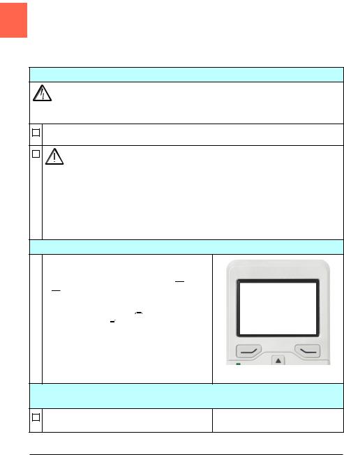
Hints on using the assistant control panel
The two commands at the bottom of the display (Options and Menu in the figure on the right), show the functions of the two softkeys  and
and  located below the display. The commands assigned to the softkeys vary depending on the context.
Use keys 
 ,
, 
 ,
,  and
and  to move the cursor and/or change values depending on the active view.
Key  shows a context-sensitive help page.
For more information, see ACX-AP-x assistant control panels user’s manual (3AUA0000085685 [English]).
1 – First start assistant guided settings: Language, motor nominal values, and date and time
Have the motor name plate data at hand.
Power up the drive.
Start-up, control with I/O and ID run 27
The First start assistant guides you through the first start-up.
The assistant begins automatically. Wait until the control panel enters the view shown on the right.
Select the language you want to use by highlighting it (if not already highlighted) and pressing  (OK).
(OK).
ACH580-31 and ACH580-34 drives: Select the supply voltage with parameter 95.01 Supply voltage:
•In the First start assistant menu, select Exit and press  (Next).
•In the Home view, press  (Menu) to enter the Main menu.
•In the Main menu, go to Parameters >
Complete list > 95 HW configuration by
selecting the correct row and pressing  (Select) repeatedly.
•Select parameter 95.01 Supply voltage and press  (Edit).
•Select supply voltage 380…415 V or
440…480 V and press  (Save).
•Go back to the Main menu by pressing  (Back) repeatedly.
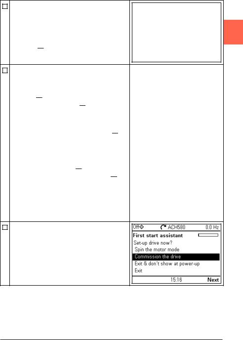
•In the Main menu, select First start assistant
and press  (Select) to enter the First start assistant menu.
•Continue with the following steps for commissioning the ACH580.
Select Commission the drive and press  (Next).
2 |
28 Start-up, control with I/O and ID run
Select the localization you want to use and press 
 (Next).
2
Change the units shown on the panel if needed.
•Go to the edit view of a selected row by pressing 
 .
.
•Scroll the view with and
and 
 .
.
Go to the next view by pressing  (Next).
To select a value in an edit view:
• Use  and
and 
 to select the value.
Press  (Save) to accept the new setting, or press
  (Cancel) to go back to the previous view without making changes.
Set the date and time as well as date and time display formats.
•Go to the edit view of a selected row by pressing 
 .
.
•Scroll the view with and
and 
 .
.
Go to the next view by pressing  (Next).
Start-up, control with I/O and ID run 29
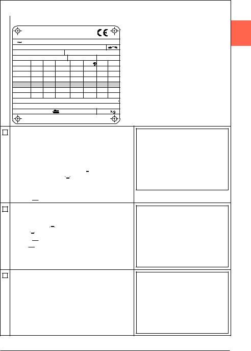
Refer to the motor nameplate for the following nominal value settings of the motor. Enter the values exactly as shown on the motor nameplate.
Example of a nameplate of an induction (asynchronous) motor: |
||||||||
|
|
|
ABB Motors |
|
2 |
|||
3 |
motor |
|
M2AA 200 MLA 4 |
|
|
|
||
|
|
|
IEC 200 M/L 55 |
|
|
|
||
|
|
|
|
No |
|
|
|
|
|
|
|
|
|
Ins.cl. |
F |
IP 55 |
|
V |
|
Hz |
kW |
r/min |
A |
cos |
IA/IN |
tE/s |
690 |
Y |
50 |
30 |
1475 |
32.5 |
0.83 |
|
|
400 |
D |
50 |
30 |
1475 |
56 |
0.83 |
|
|
660 |
Y |
50 |
30 |
1470 |
34 |
0.83 |
|
|
380 |
D |
50 |
30 |
1470 |
59 |
0.83 |
|
|
415 |
D |
50 |
30 |
1475 |
54 |
0.83 |
|
|
440 |
D |
60 |
35 |
1770 |
59 |
0.83 |
|
|
Cat. no |
3GAA 202 001 - ADA |
|
|
|
||||
|
6312/C3 |
|
6210/C3 |
|
180 |
|
||
|
|
|
|
|
|
IEC 34-1 |
|
|
Check that the motor data is correct. Values are predefined on the basis of the drive size but you should verify that they correspond to the motor.
Start with the motor type.
•Go to the edit view of a selected row by pressing 
 .
.
•Scroll the view with and
and 
 .
.
Motor nominal cos Φ and nominal torque are optional.
Press  (Next) to continue.
To change a value in an edit view:
•Use 
 and
and 
 to move the cursor left and right.
•Use  and
and  to change the value.
Press  (Save) to accept the new setting, or press
  (Cancel) to go back to the previous view without making changes.
This step is optional, and requires rotating the motor. Do not do this if it could cause any risk, or if the mechanical set-up does not allow it.
To do the direction test, select Spin the motor and press  (Next).

30 Start-up, control with I/O and ID run
Press the Hand key |
Hand on the panel to start the |
drive. |
|
2
Check the direction of the motor.
If it is forward, select Yes, motor is spinning forward and press  (Next) to continue.
If the direction is not forward, select No, fix direction and press  (Next) to continue.
The first start is now complete and the drive is ready for use.
Press  (Done) to enter the Home view.
The Home view 1 monitoring the values of the selected signals is shown on the panel.
There are eight different Home view displays. Home view 1 is the default Home view. You can browse them with keys 
 and
and 
 . See section
Home view displays on page 49.
Loading...