


XT660R

2004
XT660R(S)
XT660X(S)
5VK1-AE1
SERVICE MANUAL


EAS00000
XT660R(S)/XT660X(S) 2004
SERVICE MANUAL
©2003 by MBK Industrie
First edition, December 2003
All rights reserved.
Any reproduction or unauthorized use
without the written permission of
MBK Industrie
is expressly prohibited.
EAS00002
NOTICE
This manual was produced by MBK Industrie primarily for use by Yamaha dealers and their qualified mechanics. It is not possible to include all the knowledge of a mechanic in one manual. Therefore, anyone who uses this book to perform maintenance and repairs on Yamaha vehicles should
have a basic understanding of mechanics and the techniques to repair these types of vehicles.
Repair and maintenance work attempted by anyone without this knowledge is likely to render the
vehicle unsafe and unfit for use.
Yamaha is continually striving to improve all its models. Modifications and significant changes in
specifications or procedures will be forwarded to all authorized Yamaha dealers and will appear in
future editions of this manual where applicable.
NOTE:
_
Designs and specifications are subject to change without notice.
EAS00004
IMPORTANT MANUAL INFORMATION
Particularly important information is distinguished in this manual by the following.
The Safety Alert Symbol means ATTENTION! BECOME ALERT! YOUR
SAFETY IS INVOLVED!
Failure to follow WARNING instructions could result in severe injury or death
to the motorcycle operator, a bystander or a person checking or repairing
the motorcycle.
A CAUTION indicates special precautions that must be taken to avoid damage to the motorcycle.
A NOTE provides key information to make procedures easier or clearer.
WARNING
CAUTION:
NOTE:
EAS00007
HOW TO USE THIS MANUAL
This manual is intended as a handy, easy-to-read reference book for the mechanic. Comprehensive
explanations of all installation, removal, disassembly, assembly, repair and check procedures are
laid out with the individual steps in sequential order.
1
The manual is divided into chapters. An abbreviation and symbol in the upper right corner of
each page indicate the current chapter.
Refer to “SYMBOLS”.
2
Each chapter is divided into sections. The current section title is shown at the top of each page,
except in Chapter 3 (“PERIODIC CHECKS AND ADJUSTMENTS”), where the sub-section
title(s) appears.
3
Sub-section titles appear in smaller print than the section title.
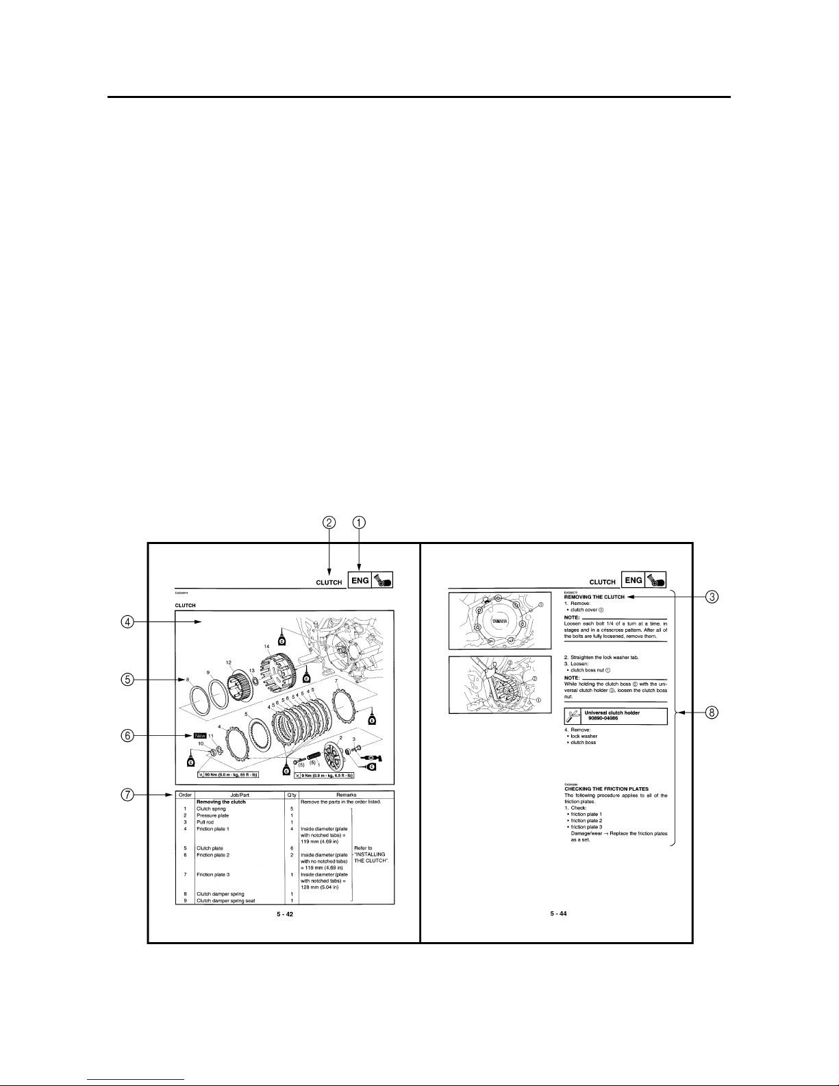
4
To help identify parts and clarify procedure steps, there are exploded diagrams at the start of
each removal and disassembly section.
5
Numbers are given in the order of the jobs in the exploded diagram. A circled number indicates a
disassembly step.
6
Symbols indicate parts to be lubricated or replaced.
Refer to “SYMBOLS”.
7
A job instruction chart accompanies the exploded diagram, providing the order of jobs, names of
parts, notes in jobs, etc.
8
Jobs requiring more information (such as special tools and technical data) are described sequentially.
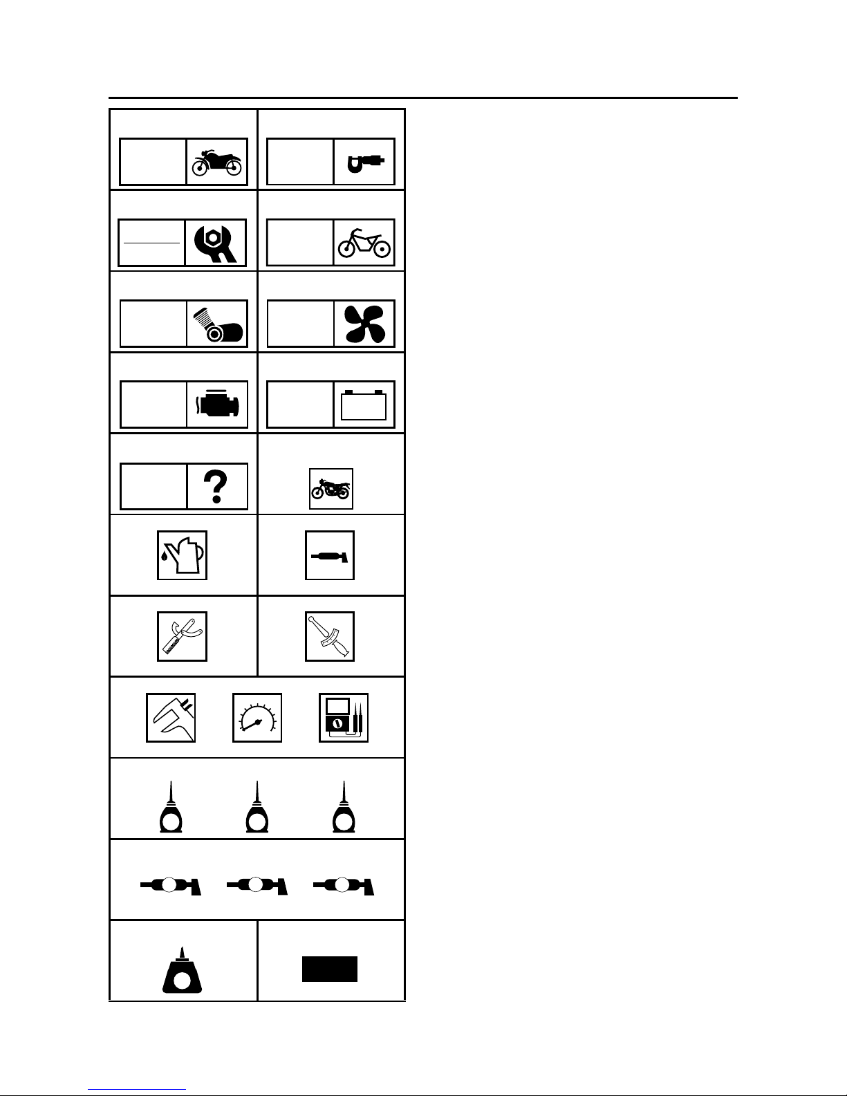
EAS00008
SYMBOLS
The following symbols are not relevant to
every vehicle.
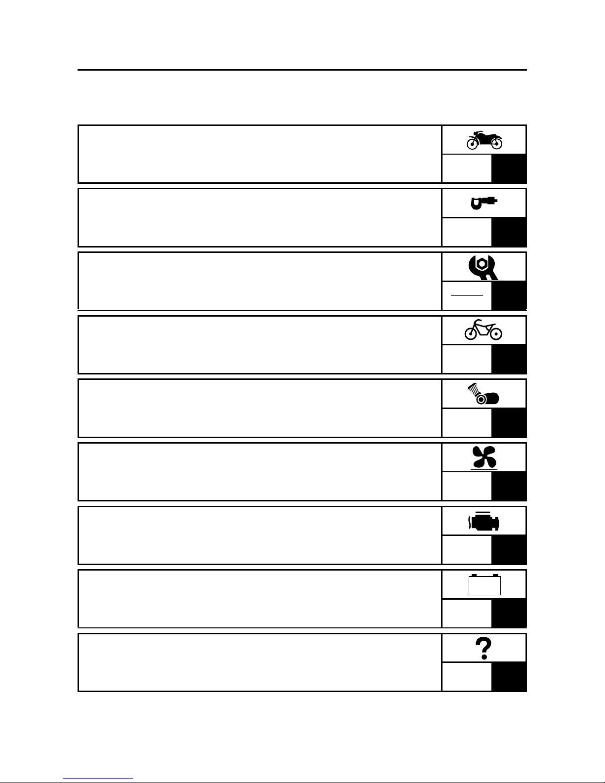
Symbols 1 to 9 indicate the subject of each
chapter.
1
General information
2
Specifications
3
Periodic checks and adjustments
4
Chassis
5
Engine
6
Cooling system
7
Fuel injection system
8
Electrical system
9
Troubleshooting
Symbols 0 to G indicate the following.
0
Serviceable with engine mounted
A
Filling fluid
B
Lubricant
C
Special tool
D
Tightening torque
E
Wear limit, clearance
F
Engine speed
G
Electrical data
Symbols H to M in the exploded diagrams
indicate the types of lubricants and lubrication
points.
H
Engine oil
I
Gear oil
J
Molybdenum-disulfide oil
K
Wheel-bearing grease
L
Lithium-soap-based grease
M
Molybdenum-disulfide grease
Symbols N to O in the exploded diagrams
indicate the following.
N
Apply locking agent (LOCTITE
®
)
O
Replace the part
12
34
56
78
90
AB
CD
EFG
HIJ
KLM
NO
GEN
INFO
SPEC
CHK
ADJ
CHAS
ENG
COOL
FI
–+
ELEC
TRBL
SHTG
T
R
.
.
E
G
M
B
LS
M
LT
New
EAS00010
TABLE OF CONTENTS
GENERAL INFORMATION
GEN
INFO
1
SPECIFICATIONS
SPEC
2
PERIODIC CHECKS AND
ADJUSTMENTS
CHK
ADJ
3
CHASSIS
CHAS
4
ENGINE
ENG
5
COOLING SYSTEM
COOL
6
FUEL INJECTION SYSTEM
FI
7
ELECTRICAL SYSTEM
ELEC
8
TROUBLESHOOTING
TRBL
SHTG
9
– +

GEN
INFO
1

GEN
INFO
CHAPTER 1
GENERAL INFORMATION
MOTORCYCLE IDENTIFICATION
..................................................................1-1
VEHICLE IDENTIFICATION NUMBER .....................................................1-1
MODEL LABEL..........................................................................................1-1
FEATURES
......................................................................................................1-2
OUTLINE ...................................................................................................1-2
FI SYSTEM................................................................................................ 1-3
IMPORTANT INFORMATION
.........................................................................1-4
PREPARATION FOR REMOVAL AND DISASSEMBLY........................... 1-4
REPLACEMENT PARTS...........................................................................1-4
GASKETS, OIL SEALS AND O-RINGS .................................................... 1-4
LOCK WASHERS/PLATES AND COTTER PINS .....................................1-5
BEARINGS AND OIL SEALS ....................................................................1-5
CIRCLIPS ..................................................................................................1-5
CHECKING THE CONNECTIONS
..................................................................1-6
SPECIAL TOOLS
............................................................................................1-7

GEN
INFO

1 - 1
GEN
INFO
EAS00014
GENERAL INFORMATION
MOTORCYCLE IDENTIFICATION
EAS00017
VEHICLE IDENTIFICATION NUMBER
The vehicle identification number 1 is
stamped into the right side of the steering head
pipe.
EAS00018
MODEL LABEL
The model label 1 is affixed to the frame. This
information will be needed to order spare
parts.
MOTORCYCLE IDENTIFICATION

1 - 2
GEN
INFO
FEATURES
EAS00019
FEATURES
EAS00896
OUTLINE
The main function of a fuel supply system is to provide fuel to the combustion chamber at the optimum air-fuel ratio in accordance with the engine operating conditions and the atmospheric temperature. In a conventional carburetor system, the air-fuel ratio of the mixture that is supplied to the
combustion chamber is created by the volume of the intake air and the fuel that is metered by the jet
used in the respective chamber.
Despite the same volume of intake air, the fuel volume requirement varies with the engine operating
conditions, such as acceleration, deceleration, or operation under a heavy load. Carburetors that
meter the fuel through the use of jets have been provided with various auxiliary devices, so that an
optimum air-fuel ratio can be achieved to accommodate the constant changes in the operating conditions of the engine.
As the requirements for engines to deliver more performance and cleaner exhaust gases increase,
it becomes necessary to control the air-fuel ratio in a more precise and finely tuned manner. To
accommodate this need, this model has adopted an electronically controlled fuel injection (FI) system in place of a conventional carburetor system. This system can achieve an optimum air-fuel ratio
required by the engine at all times by using a microprocessor that regulates the fuel injection volume
according to the engine operating conditions detected by various sensors.
Adoption of the FI system has resulted in a highly precise fuel supply, improved engine response,
better fuel economy, and reduced exhaust emissions. Furthermore, the air induction system (AI system) has been placed under computer control together with the FI system in order to realize cleaner
exhaust gases.
1
Air cut-off valve
2
Air induction system
solenoid
3
Engine trouble warning light
4
Fuel tank
5
Fuel pump
6
Fuel hose
7
Fuel injector
8
Throttle position sensor
9
Intake air temperature
sensor
0
Air filter case
A
Fuel injection system
relay
B
Battery
C
Catalytic converter
D
ECU
E
Lean angle cut-off
switch
F
Fast idle unit
G
Crankshaft position
sensor
H
Coolant temperature
sensor
I
Spark plug
J
Intake air pressure
sensor
K
Ignition coil
12
34
567890A
B
C
DEFGHI
J
K
1 - 3
GEN
INFO
FEATURES
EAS00897
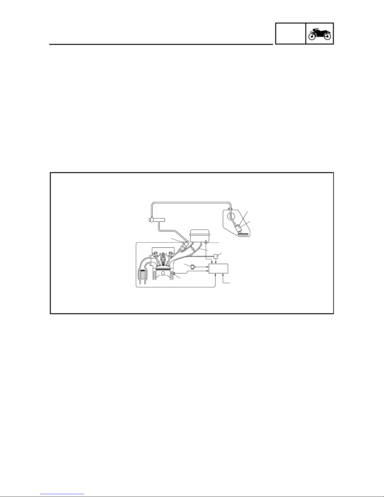
FI SYSTEM
The fuel pump delivers fuel to the injector via the fuel filter. The pressure regulator maintains the
fuel pressure that is applied to the injector at 324 kPa (3.24 kg/cm
2
, 46.1 psi) higher than the intake
manifold pressure. Accordingly, when the energizing signal from the ECU energizes the injector, the
fuel passage opens, causing the fuel to be injected into the intake manifold only during the time the
passage remains open. Therefore, the longer the length of time the injector is energized (injection
duration), the greater the volume of fuel that is supplied. Conversely, the shorter the length of time
the injector is energized (injection duration), the lesser the volume of fuel that is supplied.
The injection duration and the injection timing are controlled by the ECU. Signals that are input from
the throttle position sensor, crankshaft position sensor, intake air pressure sensor, intake air temperature sensor, and coolant temperature sensor enable the ECU to determine the injection duration. The injection timing is determined through the signal from the crankshaft position sensor. As a
result, the volume of fuel that is required by the engine can be supplied at all times in accordance
with the driving conditions.
1
Fuel pump
2
Pressure regulator
3
Fuel injector
4
Throttle body
5
Intake air temperature
sensor
6
Throttle position sensor
7
Intake air pressure
sensor
8
ECU
9
Coolant temperature
sensor
0
Crankshaft position
sensor
È
Fuel system
É
Air system
Ê
Control system
0
9
6
4
5
7
8
1
3
2
#1
È
É
Ê
Illustration is for reference only.
1 - 4
GEN
INFO
IMPORTANT INFORMATION
EAS00020
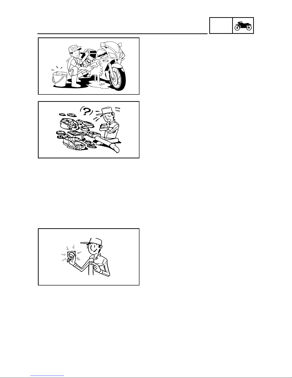
IMPORTANT INFORMATION
PREPARATION FOR REMOVAL AND
DISASSEMBLY
1. Before removal and disassembly, remove all
dirt, mud, dust and foreign material.
2. Use only the proper tools and cleaning
equipment.
Refer to “SPECIAL TOOLS”.
3. When disassembling, always keep mated
parts together. This includes gears, cylinders, pistons and other parts that have been
“mated” through normal wear. Mated parts
must always be reused or replaced as an
assembly.
4. During disassembly, clean all of the parts
and place them in trays in the order of disassembly. This will speed up assembly and
allow for the correct installation of all parts.
5. Keep all parts away from any source of fire.
EAS00021
REPLACEMENT PARTS
Use only genuine Yamaha parts for all
replacements. Use oil and grease recommended by Yamaha for all lubrication jobs.
Other brands may be similar in function and
appearance, but inferior in quality.
EAS00022
GASKETS, OIL SEALS AND O-RINGS
1. When overhauling the engine, replace all
gaskets, seals and O-rings. All gasket surfaces, oil seal lips and O-rings must be
cleaned.
2. During reassembly, properly oil all mating
parts and bearings and lubricate the oil seal
lips with grease.

1 - 5
GEN
INFO
IMPORTANT INFORMATION
EAS00023
LOCK WASHERS/PLATES AND COTTER
PINS
After removal, replace all lock washers/plates
1
and cotter pins. After the bolt or nut has
been tightened to specification, bend the lock
tabs along a flat of the bolt or nut.
EAS00024
BEARINGS AND OIL SEALS
Install bearings and oil seals so that the manufacturer’s marks or numbers are visible. When
installing oil seals, lubricate the oil seal lips
with a light coat of lithium-soap-based grease.
Oil bearings liberally when installing, if appropriate.
1
Oil seal
CAUTION:
_
Do not spin the bearing with compressed
air because this will damage the bearing
surfaces.
1
Bearing
EAS00025
CIRCLIPS
Before reassembly, check all circlips carefully
and replace damaged or distorted circlips.
Always replace piston pin clips after one use.
When installing a circlip 1, make sure the
sharp-edged corner 2 is positioned opposite
the thrust 3 that the circlip receives.
4
Shaft
1 - 6
GEN
INFO
CHECKING THE CONNECTIONS
EAS00026
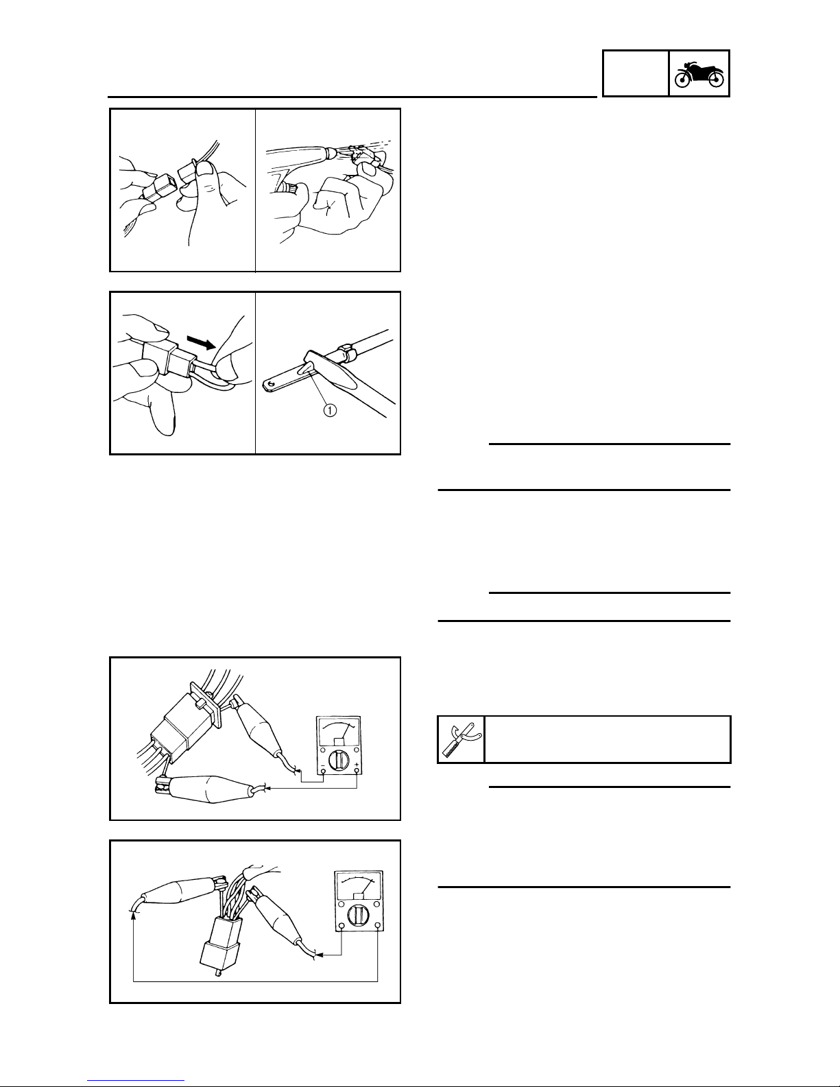
CHECKING THE CONNECTIONS
Check the leads, couplers, and connectors for
stains, rust, moisture, etc.
1. Disconnect:
• lead
• coupler
• connector
2. Check:
• lead
• coupler
• connector
Moisture → Dry with an air blower.
Rust/stains → Connect and disconnect several times.
3. Check:
• all connections
Loose connection → Connect properly.
NOTE:
_
If the pin 1 on the terminal is flattened, bend it
up.
4. Connect:
• lead
• coupler
• connector
NOTE:
_
Make sure all connections are tight.
5. Check:
• continuity
(with the pocket tester)
NOTE:
_
• If there is no continuity, clean the terminals.
• When checking the wire harness, perform
steps (1) to (3).
• As a quick remedy, use a contact revitalizer
available at most part stores.
Pocket tester
90890-03112

1 - 7
GEN
INFO
SPECIAL TOOLS
EAS00027
SPECIAL TOOLS
The following special tools are necessary for complete and accurate tune-up and assembly. Use
only the appropriate special tools as this will help prevent damage caused by the use of inappropriate tools or improvised techniques. Special tools, part numbers or both may differ depending on the
country.
When placing an order, refer to the list provided below to avoid any mistakes.
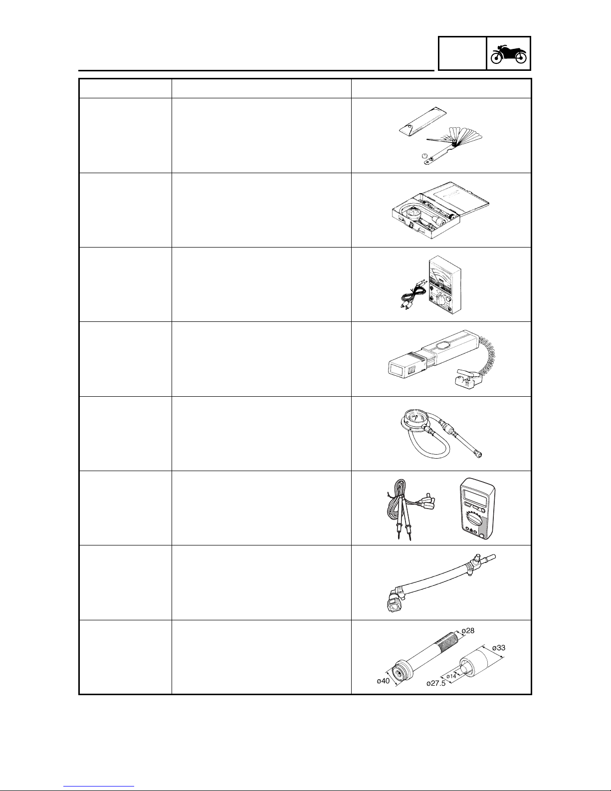
Tool No. Tool name/Function Illustration
Slide hammer bolt
90890-01083
Weight
90890-01084
Slide hammer bolt
Weight
These tools are used to remove or install
the rocker arm shafts.
90890-01135
Crankcase separating tool
This tool is used to remove the crankshaft.
Attachment
90890-01243
Compressor
90890-04019
Valve spring compressor attachment
Valve spring compressor
These tools are used to remove or install
the valve assemblies.
90890-01268
Ring nut wrench
This tool is used to loosen or tighten the
steering ring nuts.
Pot
90890-01274
Bolt
90890-01275
Crankshaft installer pot
Crankshaft installer bolt
These tools are used to install the crankshaft.
90890-01304
Piston pin puller set
This tool is used to remove the piston pin.
90890-01325
Radiator cap tester
This tool is used to check the cooling system.

1 - 8
GEN
INFO
SPECIAL TOOLS
T-handle
90890-01326
Holder
90890-01460
T-handle
Damper rod holder
These tools are used to hold the damper
rod holder when removing or installing
the damper rod.
90890-01352
Radiator cap tester adaptor
This tool is used to check the cooling system.
90890-01362
Flywheel puller
This tool is used to remove the A.C. magneto rotor.
Weight
90890-01367
Attachment
90890-01374
Fork seal driver weight
Fork seal driver attachment (ø43)
These tools are used to install the oil
seal, dust seal, and the outer tube bushing of the front fork legs.
90890-01403
Steering nut wrench
This tool is used to loosen or tighten the
steering ring nuts.
90890-01496
Radiator tester adapter
This tool is used to check the cooling system.
90890-01497
Radiator cap tester adapter
This tool is used to check the cooling system.
90890-01701
Sheave holder
This tool is used to hold the A.C. magneto
rotor when loosen or tighten the A.C.
magneto rotor nut.
Tool No. Tool name/Function Illustration
M8 × 80 mm M8 × 60 mm M8 × 150 mm
60
80
150
M8
M8
M8
1 - 9
GEN
INFO
SPECIAL TOOLS
90890-03079
Thickness gauge
This tool is used to measure the valve
clearance.
90890-03081
Compression gauge
These tools are used to measure the
engine compression.
90890-03112
Pocket tester
This tool is used to check the electrical
system.
90890-03141
Timing light
This tool is used to check the ignition timing.
90890-03153
Pressure gauge
This tool is needed to measure fuel pressure.
90890-03174
Digital circuit tester
This tool is used to check electrical system.
90890-03176
Fuel pressure adapter
This tool is needed to measure fuel pressure.
Driver
90890-04058
Installer
90890-04132
Middle driven shaft bearing driver
Mechanical seal installer
These tools are used to install the
mechanical seal.
Tool No. Tool name/Function Illustration

1 - 10
GEN
INFO
SPECIAL TOOLS
90890-04064
Valve guide remover (ø 6)
This tool is needed to remove and install
the valve guides.
90890-04065
Valve guide installer (ø 6)
This tool is needed to install the valve
guides.
90890-04066
Valve guide reamer (ø 6)
This tool is needed to rebore the new
valve guides.
90890-04082
Adaptor (Compression gauge)
This tool is needed to measure engine
compression.
90890-04086
Universal clutch holder
This tool is needed to hold the clutch
boss when removing or installing the
boss nut.
90890-04101
Valve lapper
This tool is used for lapping the valve.
Adapter
90890-04130
Spacer
90890-04144
Adapter
Spacer (crankshaft installer)
These tools are used to install the crankshaft.
90890-06754
Ignition checker
This tool is used to check the ignition system components.
Tool No. Tool name/Function Illustration

1 - 11
GEN
INFO
SPECIAL TOOLS
90890-85505
Yamaha bond No. 1215
This bond is used to seal two mating surfaces (e.g., crankcase mating surfaces).
Tool No. Tool name/Function Illustration

SPEC
2

SPEC
CHAPTER 2
SPECIFICATIONS
GENERAL SPECIFICATIONS
........................................................................2-1
ENGINE SPECIFICATIONS
............................................................................2-2
CHASSIS SPECIFICATIONS
........................................................................2-11
ELECTRICAL SPECIFICATIONS
.................................................................2-16
CONVERSION TABLE
..................................................................................2-19
GENERAL TIGHTENING TORQUE SPECIFICATIONS
...............................2-19
TIGHTENING TORQUE
.................................................................................2-20
ENGINE TIGHTENING TORQUE ...........................................................2-20
CHASSIS TIGHTENING TORQUES....................................................... 2-23
LUBRICATION POINTS AND LUBRICANT TYPES
....................................2-25
ENGINE...................................................................................................2-25
CHASSIS.................................................................................................2-27
COOLING SYSTEM DIAGRAMS
..................................................................2-28
LUBRICATION CHART
.................................................................................2-30
LUBRICATION DIAGRAMS
..........................................................................2-31
CABLE ROUTING
.........................................................................................2-35

SPEC

2 - 1
SPEC
SPECIFICATIONS
GENERAL SPECIFICATIONS
Item Standard Limit
Model code
XT660R: 5VK1 (Europe)
5VK2 (AUS)
5VK3 (GB)
XT660X: 1D21 (Europe)
1D22 (AUS)
1D23 (GB)
----
----
----
----
----
----
Dimensions
Overall length 2,240 mm (88.2 in) (XT660R)
2,150 mm (84.6 in) (XT660X)
----
----
Overall width 845 mm (33.3 in) (XT660R)
865 mm (34.1 in) (XT660X)
----
----
Overall height 1,230 mm (48.4 in) (XT660R)
1,210 mm (47.6 in) (XT660X)
----
----
Seat height 865 mm (34.1 in) (XT660R)
870 mm (34.3 in) (XT660X)
----
----
Wheelbase 1,505 mm (59.3 in) (XT660R)
1,490 mm (58.7 in) (XT660X)
----
----
Minimum ground clearance 210 mm (8.27 in) (XT660R)
205 mm (8.07 in) (XT660X)
----
----
Minimum turning radius 2,400 mm (94.5 in) ----
Weight
Wet (with oil and a full fuel tank) 181 kg (399 lb) (XT660R)
186 kg (410 lb) (XT660X)
----
---Maximum load (total of cargo, rider,
passenger, and accessories)
186 kg (410 lb) ----
GENERAL SPECIFICATIONS
2 - 2
SPEC
ENGINE SPECIFICATIONS
ENGINE SPECIFICATIONS
Item Standard Limit
Engine
Engine type Liquid-cooled, 4-stroke, SOHC ---Displacement 660 cm
3
(40.27 cu · in) ----
Cylinder arrangement Forward-inclined single cylinder ---Bore × stroke 100.0 × 84.0 mm (3.94 × 3.31 in) ---Compression ratio 10.00 : 1 ---Engine idling speed 1,300 ~ 1,500 r/min ---Water temperature 80 °C (176 °F) ----
Oil temperature 55 ~ 60 °C (131 ~ 140 °F) ---Standard compression pressure
(at sea level)
650 kPa (6.5 kg/cm
2
, 92.4 psi)
at 800 r/min
----
Fuel
Recommended fuel Premium unleaded gasoline only ---Fuel tank capacity
Total (including reserve) 15.0 L (3.30 Imp gal, 3.96 US gal) ---Reserve only 5.0 L (1.10 Imp gal, 1.32 US gal) ----
Engine oil
Lubrication system Dry sump ---Recommended oil
Refer to the chart for engine oil grade.
API service SE, SF, SG type or higher
----
Quantity
Total amount 2.90 L (2.55 Imp qt, 3.07 US qt) ---Periodic oil change 2.50 L (2.20 Imp qt, 2.64 US qt) ---With oil filter replacement 2.60 L (2.29 Imp qt, 2.75 US qt) ----
Oil filter
Oil filter type Paper ---Bypass valve opening pressure 40.0 ~ 80.0 kPa
(0.40 ~ 0.80 kg/cm
2
, 5.8 ~ 11.6 psi)
----
Pressure check location Oil filter chamber ----
-20 -10 0
10
20 30
40
50 ˚C
SAE 10W-30
SAE 15W-40
SAE 20W-40
SAE 20W-50
SAE 10W-40
2 - 3
SPEC
ENGINE SPECIFICATIONS
Oil pump
Oil pump type Trochoid ---Inner-rotor-to-outer-rotor-tip clearance
0.07 ~ 0.12 mm (0.0028 ~ 0.0047 in) 0.2 mm
(0.008 in)
Outer-rotor-to-oil-pump-housing
clearance
0.03 ~ 0.08 mm (0.0012 ~ 0.0031 in) 0.15 mm
(0.0059 in)
Oil-pump-housing-to-inner-rotor-andouter-rotor clearance
0.03 ~ 0.08 mm (0.0012 ~ 0.0031 in) 0.15 mm
(0.0059 in)
Cooling system
Radiator capacity 1.00 L (0.88 Imp, 1.06 US qt) ---Radiator cap opening pressure 110.0 ~ 140.0 kPa
(1.10 ~ 1.40 kg/cm
2
, 16.0 ~ 20.3 psi)
----
Radiator core
Width 280.0 mm (11.02 in) ---Height 158.0 mm (6.22 in) ---Depth 23.0 mm (0.91 in) ----
Coolant reservoir
Capacity 0.25 L (0.22 Imp, 0.26 US qt) --- <From low to full level> 0.15 L (0.13 Imp, 0.16 US qt) ----
Water pump
Water pump type Single-suction centrifugal pump ---Reduction ratio 27/28 (0.964) ---Maximum impeller shaft tilt ---- 0.15 mm
(0.006 in)
Starting system type
Electric starter ----
Fuel injector
Model/manufacturer 297500-0390/DENSO ---Quantity 1 ----
Spark plug
Model/manufacturer × quantity CR7E/NGK × 1 ---Spark plug gap 0.7 ~ 0.8 mm (0.028 ~ 0.031 in) ----
Cylinder head
Volume 59.10 ~ 60.50 cm
3
(3.61 ~ 3.69 cu · in) ----
Maximum warpage ---- 0.03 mm
(0.0012 in)
Item Standard Limit
2 - 4
SPEC
ENGINE SPECIFICATIONS
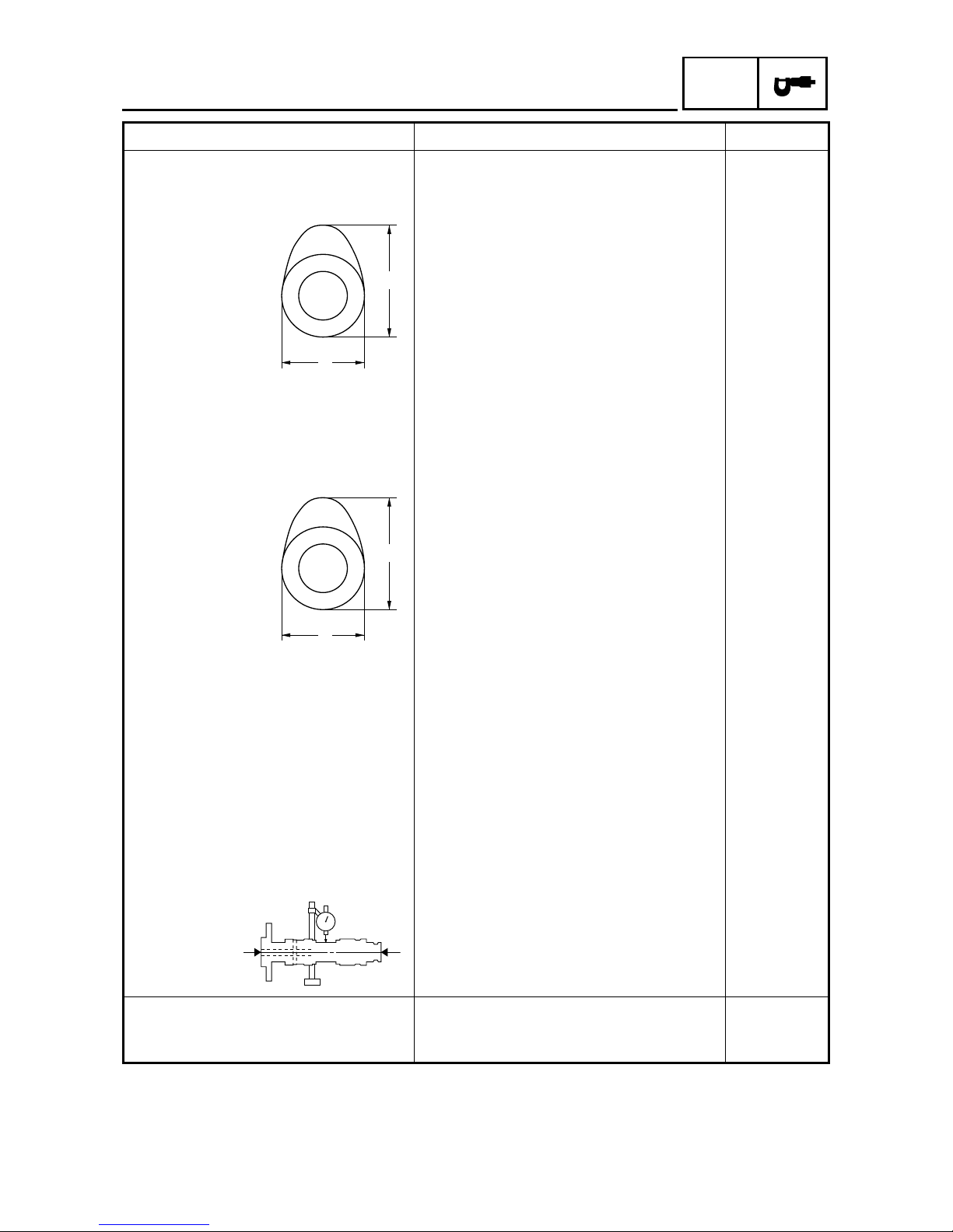
Camshaft
Drive system Chain drive (left) ---Intake camshaft lobe dimensions
Measurement A 43.488 ~ 43.588 mm (1.7121 ~ 1.7161 in) 43.338 mm
(1.7062 in)
Measurement B 36.959 ~ 37.059 mm (1.4551 ~ 1.4590 in) 36.840 mm
(1.4504 in)
Exhaust camshaft lobe dimensions
Measurement A 43.129 ~ 43.229 mm (1.6980 ~ 1.7019 in) 42.983 mm
(1.6922 in)
Measurement B 37.007 ~ 37.107 mm (1.4570 ~ 1.4609 in) 36.886 mm
(1.4522 in)
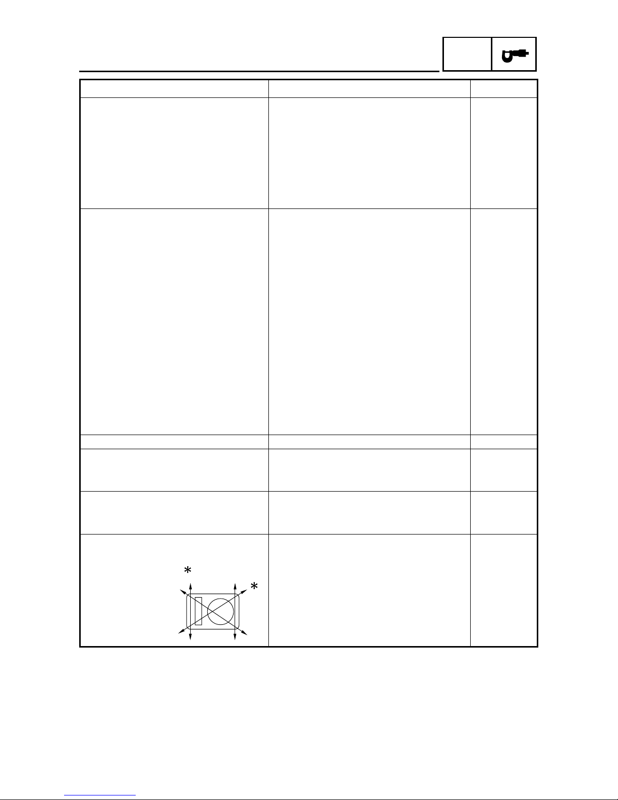
Valve timing
Intake - open (B.T.D.C.) 25° ----
Intake - closed (A.B.D.C.) 55° ---Exhaust - open (B.B.D.C.) 60° ----
Exhaust - closed (A.T.D.C.) 20° ---Overlap angle “A” 45° ----
Maximum camshaft runout ---- 0.040 mm
(0.0016 in)
Timing chain
Model/number of links 98 × RH2010/126 ---Tensioning system Automatic ----
Item Standard Limit
A
B
A
B
 Loading...