


Thank you for purchasing an e-book through Korn’s Bookshop. If you have any problems or questions you can get in touch with me via email on books@kornel.com. I hope you are satisfied with your purchase and enjoy your book, happy reading!
Check out my other great books by visiting Korn’s Bookshop on eBay.
Please note:
You may not copy, reproduce or redistribute this e-book in any form for commercial purposes. You are hereby granted a licence to read, store and print this book for personal use only. If you think you may have purchased this book from an unauthorised source either on eBay or elsewhere please contact me for clarification. Kornel Lambert (eBay ID ‘korn_london’) is the only permitted distribution agent for these books. Help stamp out piracy!
EAS00002
NOTICE
This manual was written by the Yamaha Motor Company primarily for use by Yamaha dealers and their qualified mechanics. It is not possible to put an entire mechanic's education into one manual, so it is assumed that persons using this book to perform maintenance and repairs on Yamaha motorcycle has a basic understanding of the mechanical concepts and procedures inherent in motorcycle repair technology. Without such knowledge, attempted repairs or service to this model may render it unfit to use and/or unsafe.
Yamaha Motor Cmpany, Ltd. is continually striving to improve all models manufactured by Yamaha. Modifications and significant changes in specifications or procedures will be forwarded to all Authorized yamaha dealers and will, where applicable, appear in future editions of this manual.
NOTE:
PARTICURARLY IMPORTANT INFORMATION
This materials distinguished by the following notation.
|
The Safety Alert Symbol means ATTENTION! BECOME ALERT! YOUR |
|||
|
SAFETY IS INVOLVED! |
|||
|
Failure to follow WARNING instructions could result in severe injury or death to |
|||
|
the motorcycle operator, a bystander or |
|
|
|
|
a person checking or repairing the mo- |
|||
|
torcycle. |
|||
|
A CAUTION indicates special precautions that must be taken to avoid damage |
|||
CAUTION: |
||||
|
to the motorcycle. |
|||
NOTE: |
||||
A NOTE provides key information to make procedures easier or clearer. |
||||
EAS00007
HOW TO USE THIS MANUAL
This manual is intended as a handy, easy-to-read reference book for the mechanic. Comprehensive explanations of all installation, removal, disassembly, assembly, repair and check procedures are laid out with the individual steps in sequential order.
1The manual is divided into chapters. An abbreviation and symbol in the upper right corner of each page indicate the current chapter.
Refer to ªSYMBOLSº.
2Each chapter is divided into sections. The current section title is shown at the top of each page, except in Chapter 3 (ªPERIODIC CHECKS AND ADJUSTMENTSº), where the sub-section title(-s) appears.
3Sub-section titles appear in smaller print than the section title.
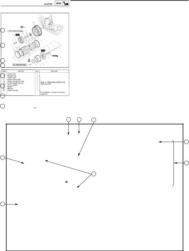
4To help identify parts and clarify procedure steps, there are exploded diagrams at the start of each removal and disassembly section.
5Numbers are given in the order of the jobs in the exploded diagram. A circled number indicates a disassembly step.
6Symbols indicate parts to be lubricated or replaced.
Refer to ªSYMBOLSº.
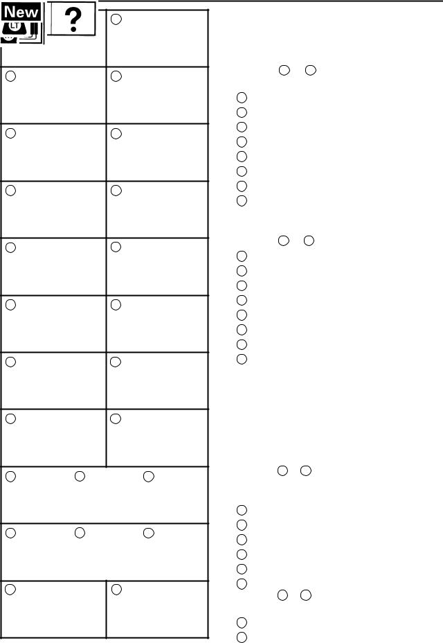
7A job instruction chart accompanies the exploded diagram, providing the order of jobs, names of parts, notes in jobs, etc.
8Jobs requiring more information (such as special tools and technical data) are described sequentially.
2 1 4
3
5
8
 6
6
7
1 |
2 |
GEN |
SPEC |
|
INFO |
||
|
||
3 |
4 |
|
CHK |
ENG |
|
ADJ |
||
|
||
5 |
6 |
|
CARB |
CHAS |
|
7 |
8 |
|
ELEC |
TRBL |
|
SHTG |
||
|
||
9 |
10 |
11 |
|
12 |
13 |
|
14 |
15 |
|
16 |
17 |
18 |
19 |
20 |
21 |
22 |
23 |
|
24 |
EAS00009
SYMBOLS
The following symbols are not relevant to every vehicle.
Symbols 1 to 8 indicate the subject of each chapter.
1General information
2Specifications
3Periodic checks and adjustments
4Engine
5Carburetor(-s)
6Chassis
7Electrical system
8Troubleshooting
Symbols 9 to 16 indicate the following.
9 Serviceable with engine mounted
10Filling fluid
11Lubricant
12Special tool
13Tightening torque
14Wear limit, clearance
15Engine speed
16Electrical data
Symbols 17 to 22 in the exploded diagrams indicate the types of lubricants and lubrication points.
17Engine oil
18Gear oil
19Molybdenum disulfide oil
20Wheel bearing grease
21Lithium soap base grease
22Molybdenum disulfide grease
Symbols 23 to 24 in the exploded diagrams indicate the following:
23Apply locking agent (LOCTITE )
24Replace the part

EAS00013
INDEX
GENERAL INFORMATION |
|
|
|
|
|
|
GEN |
1 |
|||
|
|
INFO |
|||
|
|
|
|
|
|
SPECIFICATIONS |
|
|
|
|
|
|
SPEC |
2 |
|||
|
|||||
|
|
||||
|
|
|
|
|
|
PERIODIC INSPECTION AND |
|
|
|
|
|
|
CHK |
3 |
|||
|
|||||
ADJUSTMENTS |
|
||||
|
ADJ |
|
|||
|
|
|
|
|
|
ENGINE OVERHAUL |
|
|
|
|
|
|
ENG |
4 |
|||
|
|||||
|
|
||||
|
|
|
|
|
|
CARBURETORS |
|
|
|
|
|
CARB |
5 |
||||
|
|||||
|
|
|
|
|
|
CHASSIS |
|
|
|
|
|
CHAS |
6 |
||||
|
|||||
|
|
|
|
|
|
ELECTRICAL |
|
|
|
|
|
|
ELEC |
7 |
|||
|
|||||
|
|
||||
|
|
|
|
|
|
TROUBLESHOOTING |
|
|
|
|
|
|
TRBL |
8 |
|||
|
SHTG |
||||

INFOGEN 1
GEN
INFO
CHAPTER 1.
GENERAL INFORMATION
MOTORCYCLE IDENTIFICATION . . . . . . . . . . . . . . . . . . . . . . . . . . . . . . . 1-1 VEHICLE IDENTIFICATION NUMBER . . . . . . . . . . . . . . . . . . . . . . . . . 1-1 MODEL CODE . . . . . . . . . . . . . . . . . . . . . . . . . . . . . . . . . . . . . . . . . . . . . 1-1
IMPORTANT INFORMATION . . . . . . . . . . . . . . . . . . . . . . . . . . . . . . . . . . . . 1-2 PREPARATION FOR REMOVAL AND DISASSEMBLY . . . . . . . . . . 1-2 REPLACEMENT PARTS . . . . . . . . . . . . . . . . . . . . . . . . . . . . . . . . . . . . . 1-2 GASKETS, OIL SEALS AND O-RINGS . . . . . . . . . . . . . . . . . . . . . . . . 1-2 LOCK WASHERS/PLATES AND COTTER PINS . . . . . . . . . . . . . . . . 1-3 BEARINGS AND OIL SEALS . . . . . . . . . . . . . . . . . . . . . . . . . . . . . . . . . 1-3 CIRCLIPS . . . . . . . . . . . . . . . . . . . . . . . . . . . . . . . . . . . . . . . . . . . . . . . . . . 1-3
CHECKING OF THE CONNECTIONS . . . . . . . . . . . . . . . . . . . . . . . . . . . . 1-4
SPECIAL TOOLS . . . . . . . . . . . . . . . . . . . . . . . . . . . . . . . . . . . . . . . . . . . . . . 1-5
GEN
MOTORCYCLE IDENTIFICATION INFO
EAS00014
GENERAL INFORMATION
MOTORCYCLE IDENTIFICATION
EAS00017
VEHICLE IDENTIFICATION NUMBER (For E)
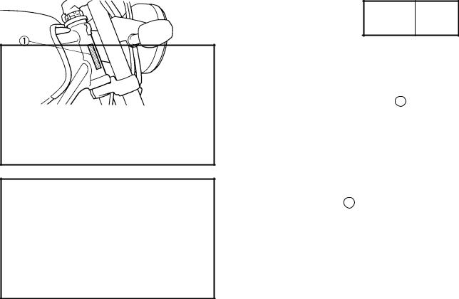
The vehicle identification number 1 is stamped into the right side of the steering head.
EAS00018
MODEL CODE
The model code label 1 is affixed to the frame. This information will be needed to order spare parts.
1-1
GEN
IMPORTANT INFORMATION INFO
EAS00020
IMPORTANT INFORMATION
PREPARATION FOR REMOVAL AND DIS-
ASSEMBLY
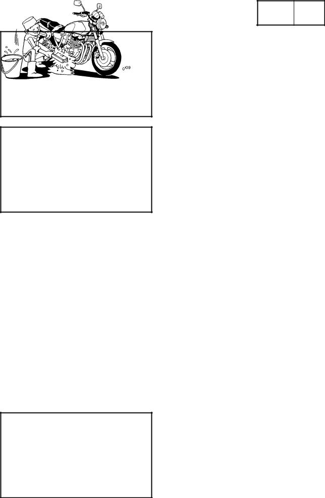
1.Before removal and disassembly, remove all dirt, mud, dust, and foreign material.
2.Use only the proper tools and cleaning equipment.
Refer to ªSPECIAL TOOLSº.
3.When disassembling, always keep mated parts together. This includes gears, cylinders, pistons and other parts that have been ªmatedº through normal wear. Mated parts must always be reused or replaced as an assembly.
4.During disassembly, clean all of the parts and place them in trays in the order of disassembly. This will speed up assembly and allow for the correct installation of all parts.
5.Keep all parts away from any source of fire.
EAS00021
REPLACEMENT PARTS
Use only genuine Yamaha parts for all replacements. Use oil and grease recommended by Yamaha for all lubrication jobs. Other brands may be similar in function and appearance, but inferior in quality.
EAS00022
GASKETS, OIL SEALS AND O-RINGS
1.When overhauling the engine, replace all gaskets, seals and O-rings. All gasket surfaces, oil seal lips and O-rings must be cleaned.
2.During reassembly, properly oil all mating parts and bearings and lubricate the oil seal lips with grease.
1-2
GEN
IMPORTANT INFORMATION INFO
EAS00023
LOCK WASHERS/PLATES AND COTTER PINS
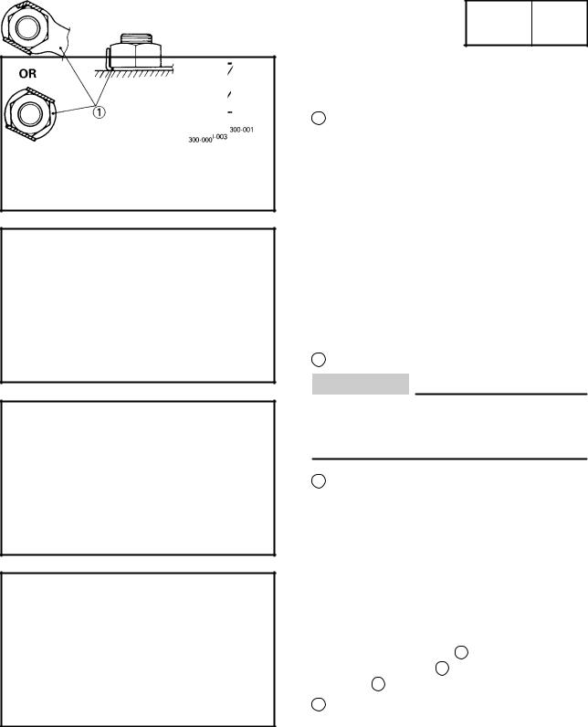
After removal, replace all lock washers/plates 1 and cotter pins. After the bolt or nut has been tightened to specification, bend the lock washer tabs and the cotter pin ends along a flat of the bolt or nut.
EAS00024
BEARINGS AND OIL SEALS
1. Install bearings and oil seals so that the manufacturer's marks or numbers are visible. When installing oil seals, lubricate the oil seal lips with a light coat of lithium soap base grease. Oil bearings liberally when installing, if appropriate.
1 Oil seal
CAUTION:
Do not spin the bearing with compressed air because this will damage the bearing surfaces.
1 Bearing
EAS00025
CIRCLIPS
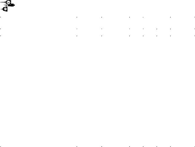
Before reassembly, check all circlips carefully and replace damaged or distorted circlips. Always replace piston pin clips after one use. When installing a circlip 1 , make sure that the sharp-edged corner 2 is positioned opposite the thrust 3 that the circlip receives.
4 Shaft
1-3
GEN
CHECKING THE CONNECTIONS INFO
EAS00026
CHECKING THE CONNECTIONS
Check the leads, couplers, and connectors for stains, rust, moisture, etc.
1.Disconnect:
lead
coupler
connector
2.Check:
lead
coupler
connector
Moisture Dry with an air blower. Rust/stains Connect and disconnect several times.
3.Check:
all connections
Loose connection Connect properly.
NOTE:
If the pin 1 on the terminal is flattened, bend it up.
4.Connect:
lead
coupler
connector
NOTE:
Make sure that all connections are tight.
5.Check:
continuity
(with a pocket tester)
Pocket tester 90890-03112
NOTE:
If there is no continuity, clean the terminals.
When checking the wire harness, perform steps (1) to (3).
As a quick remedy, use a contact revitalizer available at most part stores.
1-4
GEN
SPECIAL TOOLS INFO
EB104000
SPECIAL TOOLS
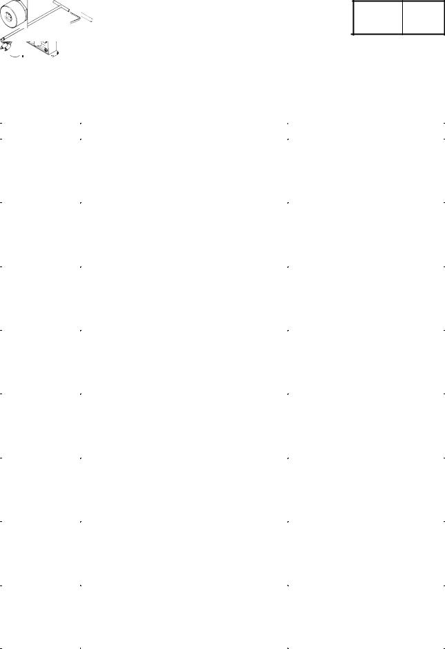
The following special tools are necessary for complete and accurate tune-up and assembly.
Use only the appropriate special tools as this will help prevent damage caused by the use of inappropriate tools or improvised techniques.
When placing an order, refer to the list provided below to avoid any mistakes.
Tool No. |
Tool name/Function |
Illustration |
|
|
|
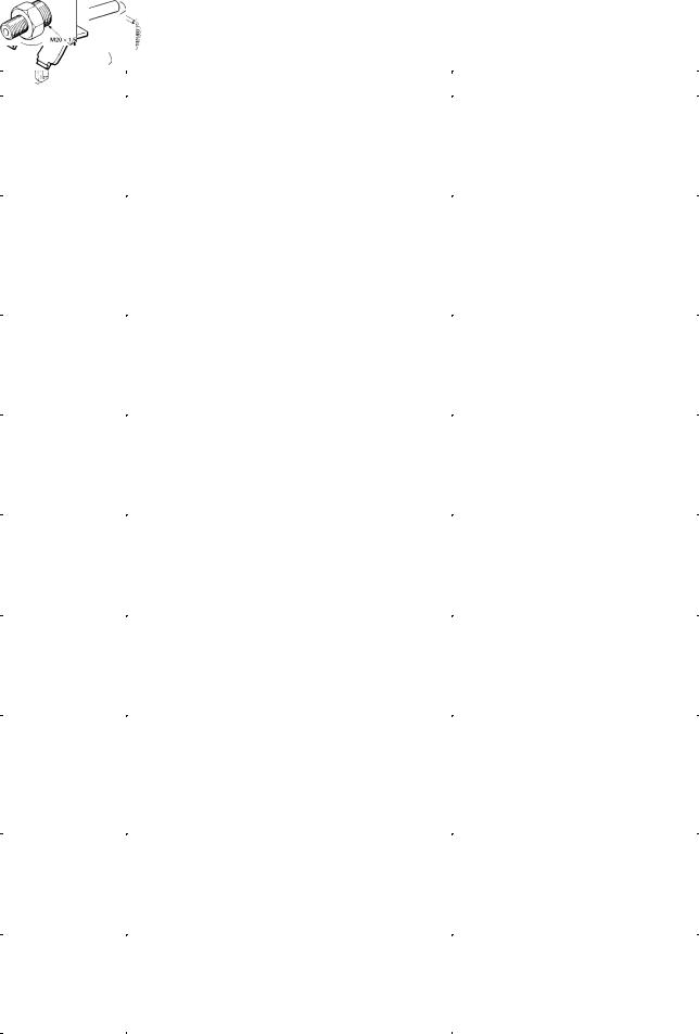
90890-01268 |
Exhaust & steering nut wrench |
|
90890-01403 |
Ring nut wrench |
|
|
This tools are used to loosen and tighten |
|
|
the steering ring nut. |
|
|
|
|
90890-01304 |
Piston pin puller |
|
|
This tool is used to remove the piston pins. |
|
|
|
|
90890-01312 |
Fuel level gauge |
|
|
This tool is used to measure the fuel level in |
|
|
the float chamber. |
|
|
|
|
90890-01367 |
Fork seal driver weight |
|
90890-01374 |
Fork seal driver attachment (ù43) |
|
|
These tools are used when installing the |
|
|
fork seal. |
|
|
|
|
90890-01326 |
T-handle |
|
90890-01327 |
Damper rod holder |
|
|
These tools are used to hold the damper |
|
|
rod assembly when loosening or tightening |
|
|
the damper rod assembly bolt. |
|
|
|
|
90890-03081 |
Compression gauge |
|
90890-04082 |
Adapter |
|
|
These tools are used to measure engine |
|
|
compression. |
|
|
|
|
90890-03094 |
Vacuum gauge |
|
|
This guide is used to synchronize the car- |
|
|
buretors. |
|
|
|
|
90890-03112 |
Pocket tester |
|
|
This tool is used to check the electrical sys- |
|
|
tem. |
|
|
|
|
1-5
|
SPECIAL TOOLS |
|
|
GEN |
|
|
|
|
|
INFO |
|
||
|
|
|
|
|||
Tool No. |
Tool name/Function |
|
Illustration |
|||
|
|
|
|
|
|
|
90890-03113 |
Engine tachometer |
|
|
|
|
|
|
This tool is used to check engine speed. |
|
|
|
|
|
|
|
|
|
|
|
|
90890-03141 |
Timing light |
|
|
|
|
|
|
This tool is used to check the ignition tim- |
|
|
|
|
|
|
ing. |
|
|
|
|
|
|
|
|
|
|
|
|
90890-03158 |
Carburetor angle driver |
|
|
|
|
|
|
This tool is used to turn the pilot screw |
|
|
|
|
|
|
when adjusting the engine idling speed. |
|
|
|
|
|
|
|
|
|
|
|
|
90890-04016 |
Valve guide reamer, remover and installer |
|
|
|
|
|
|
(5.5 mm) |
|
|
|
|
|
|
These tools are used to rebore, remove and |
|
|
|
|
|
|
install the valve guide. |
|
|
|
|
|
|
|
|
|
|
|
|
90890-04019 |
Valve spring compressor |
|
|
|
|
|
|
This tool is used to remove or install the |
|
|
|
|
|
|
valve assemblies. |
|
|
|
|
|
|
|
|
|
|
|
|
90890-03153 |
Oil pressure gauge |
|
|
|
|
|
90890-03124 |
Oil pressure adaptor B |
|
|
|
|
|
|
These tools are used to measure the engine |
|
|
|
|
|
|
oil pressure. |
|
|
|
|
|
|
|
|
|
|
|
|
90890-04086 |
Clutch holding tool |
|
|
|
|
|
|
This tool is used to hold the clutch boss |
|
|
|
|
|
|
when removing or installing the clutch boss |
|
|
|
|
|
|
nut. |
|
|
|
|
|
|
|
|
|
|
|
|
90890-04101 |
Valve lapper |
|
|
|
|
|
|
This tool is used for removing and installing |
|
|
|
|
|
|
the valve lifter and for lapping the valve. |
|
|
|
|
|
|
|
|
|
|
|
|
90890-04110 |
Tappet adjusting tool |
|
|
|
|
|
|
This tool is necessary to replace valve ad- |
|
|
|
|
|
|
justing pads. |
|
|
|
|
|
|
|
|
|
|
|
|
1-6
|
SPECIAL TOOLS |
|
|
GEN |
|
|
|
|
|
INFO |
|
||
|
|
|
|
|||
Tool No. |
Tool name/Function |
|
Illustration |
|||
|
|
|
|
|
|
|
90890-06754 |
Ignition checker |
|
|
|
|
|
|
This tool is used to check the ignition sys- |
|
|
|
|
|
|
tem components. |
|
|
|
|
|
|
|
|
|
|
|
|
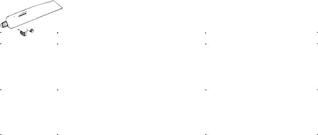
90890-85505 |
Yamaha bond No. 1215 |
|
|
|
|
|
|
This bond is used to seal two mating sur- |
|
|
|
|
|
|
faces (e.g., crankcase mating surfaces). |
|
|
|
|
|
|
|
|
|
|
|
|
1-7
SPEC 2
SPEC 


CHAPTER 2.
SPECIFICATIONS
GENERAL SPECIFICATIONS . . . . . . . . . . . . . . . . . . . . . . . . . . . . . . . . . . . 2-1
MAINTENANCE SPECIFICATIONS . . . . . . . . . . . . . . . . . . . . . . . . . . . . . . 2-4 ENGINE . . . . . . . . . . . . . . . . . . . . . . . . . . . . . . . . . . . . . . . . . . . . . . . . . . . 2-4 CHASSIS . . . . . . . . . . . . . . . . . . . . . . . . . . . . . . . . . . . . . . . . . . . . . . . . . . 2-14 ELECTRICAL . . . . . . . . . . . . . . . . . . . . . . . . . . . . . . . . . . . . . . . . . . . . . . 2-18
CONVERSION TABLE . . . . . . . . . . . . . . . . . . . . . . . . . . . . . . . . . . . . . . . . . . 2-20
GENERAL TIGHTENING TORQUES . . . . . . . . . . . . . . . . . . . . . . . . . . . . . 2-20
LUBRICATION POINT AND GRADE OF LUBRICANT . . . . . . . . . . . . . 2-21 ENGINE . . . . . . . . . . . . . . . . . . . . . . . . . . . . . . . . . . . . . . . . . . . . . . . . . . . 2-21 CHASSIS . . . . . . . . . . . . . . . . . . . . . . . . . . . . . . . . . . . . . . . . . . . . . . . . . . 2-22
LUBRICATION DIAGRAMS . . . . . . . . . . . . . . . . . . . . . . . . . . . . . . . . . . . . . 2-23
CABLE ROUTING . . . . . . . . . . . . . . . . . . . . . . . . . . . . . . . . . . . . . . . . . . . . . 2-26
|
GENERAL SPECIFICATIONS |
SPEC |
|
|
|
|
|
|
|
|
SPECIFICATIONS |
|||
GENERAL SPECIFICATIONS |
||||
|
|
|||
Model |
XJR1300(L) |
|||
|
|
|||
Model code: |
5EA2/5EA3/5EA4 |
|||
|
|
|
|
|
Dimensions: |
|
|
|
|
Overall length |
2175 mm (GB) (D) (NL) (B) (F) (E) (P) (I) (GR) |
|||
|
(SF) (AUS) |
|||
|
2250 mm (N) (SF) (G) (A) |
|||
Overall width |
775 mm |
|||
Overall height |
1115 mm |
|||
Seat height |
775 mm |
|||
Wheelbase |
1500 mm |
|||
Minimum ground clearance |
120 mm |
|||
Minimum turning radius |
2800 mm |
|||
|
|
|
|
|
Basic weight: |
|
|
|
|
With oil and full fuel tank |
253 kg |
|||
|
|
|
|
|
Engine: |
|
|
|
|
Engine type |
Air-cooled 4-stroke, DOHC |
|||
Cylinder arrangement |
Forward-inclined parallel 4-cylinder |
|||
Displacement |
1250 cm3 |
|||
Bore stroke |
79.0 63.8 mm |
|||
Compression ratio |
9.7: 1 |
|
|
|
Compression pressure (STD) |
1050 kPa (10.5 kg/cm2,10.5 bar) at 400 r/min |
|||
Starting system |
Electric starter |
|||
Lubrication system: |
Wet sump |
|||
|
|
|||
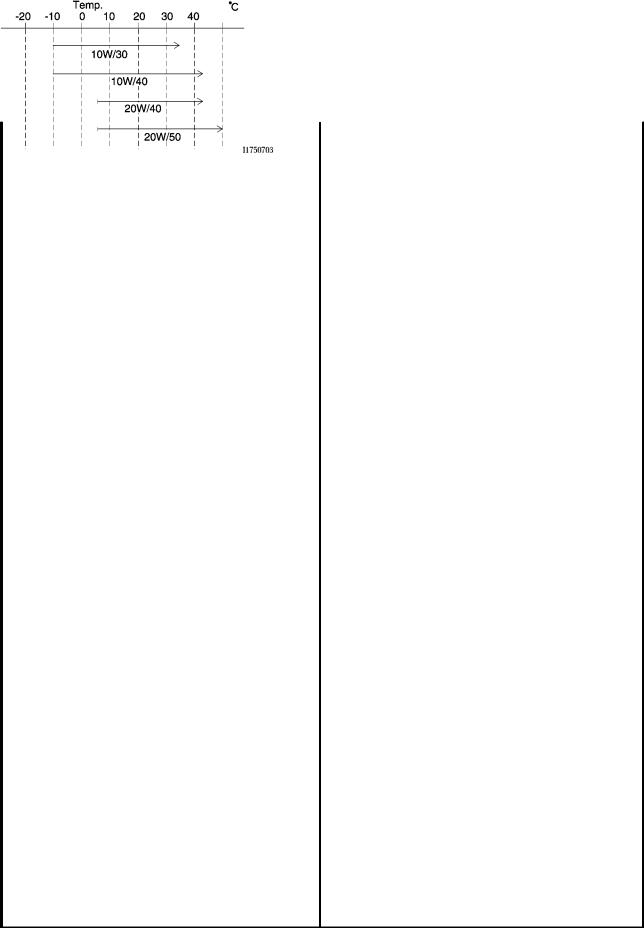
Oil type or grade: |
SE or higher grade |
|||
Engine oil |
|
|
|
|
Engine oil |
|
Periodic oil change |
3.0 L |
With oil filter replacement |
3.35 L |
Total amount |
4.2 L |
Oil cooler capacity (including all routes) |
0.2 L |
|
|
Air filter: |
Dry type element |
|
|
Fuel: |
|
Type |
Regular unleaded gasoline |
Fuel tank capacity |
21 L |
Fuel reserve amount |
4.5 L |
2-1

|
GENERAL SPECIFICATIONS |
|
SPEC |
|
||
|
|
|
|
|
|
|
|
|
|
||||
|
Model |
XJR1300(L) |
||||
|
|
|
|
|
|
|
Carburetor: |
|
|
|
|
|
|
Type/quantity |
|
BS36/4 |
|
|
||
Manufacturer |
|
MIKUNI |
|
|
||
|
|
|
|
|
|
|
Spark plug: |
|
|
|
|
|
|
Type quantity |
DPR8EA-9/X24EPR-U9 4 |
|
|
|||
Manufacturer |
|
NGK/DENSO |
|
|
||
Spark plug gap |
|
0.8 X 0.9 mm |
|
|
||
|
|
|
|
|
||
Clutch type: |
|
Wet, multiple-disc |
|
|
||
|
|
|
|
|
|
|
Transmission: |
|
|
|
|
|
|
Primary reduction system |
Spur gear |
|
|
|||
Primary reduction ratio |
98/56 (1.750) |
|
|
|
|
|
Secondary reduction system |
Chain drive |
|
|
|||
Secondary reduction ratio |
38/17 (2.235) |
|
|
|
|
|
Transmission type |
Constant mesh 5-speed |
|
|
|||
Operation |
|
Left foot operation |
|
|
||
Gear ratio 1st |
|
40/14 (2.857) |
|
|
|
|
2nd |
36/18 (2.000) |
|
|
|
|
|
3rd |
|
33/21 (1.571) |
|
|
|
|
4th |
|
31/24 (1.292) |
|
|
|
|
5th |
|
29/26 (1.115) |
|
|
|
|
|
|
|
|
|
|
|
Chassis: |
|
|
|
|
|
|
Frame type |
|
Double cradle |
|
|
||
Caster angle |
|
25.5 |
|
|
|
|
Trail |
|
100 mm |
|
|
||
|
|
|
|
|
|
|
Tire: |
|
|
|
|
|
|
Type |
|
Tubeless |
|
|
||
Size |
front |
120/70ZR17 (58W) |
|
|
||
|
rear |
180/55ZR17 (73W) |
|
|
||
Manufacturer |
front |
MICHELIN/DUNLOP/BRIDGESTONE |
||||
|
rear |
MICHELIN/DUNLOP/BRIDGESTONE |
||||
Type |
front |
MACADAM 90X/D207F/BT57F |
||||
|
rear |
MACADAM 90X/D207/BT57R |
||||
|
|
|
|
|
|
|
Tire pressure (cold tire): |
|
|
|
|
|
|
Maximum load-except motorcycle |
207 kg |
|
|
|||
Loading condition A * |
0 X 90 kg |
|
|
|||
|
front |
250 kPa (2.5 kg/cm2, 2.5 bar) |
||||
|
rear |
250 kPa (2.5 kg/cm2, 2.5 bar) |
||||
Loading condition B * |
90 X 207 kg |
|
|
|||
|
front |
250 kPa (2.5 kg/cm2, 2.5 bar) |
||||
|
rear |
290 kPa (2.9 kg/cm2, 2.9 bar) |
||||
High-speed riding |
250 kPa (2.5 kg/cm2, 2.5 bar) |
|||||
|
front |
|||||
|
rear |
290 kPa (2.9 kg/cm2, 2.9 bar) |
||||
*Load is the total weight of cargo, rider, passenger, and accessories.
2-2
|
|
GENERAL SPECIFICATIONS |
|
SPEC |
|
||
|
|
|
|
|
|
|
|
|
|
|
|
|
|||
|
Model |
|
|
XJR1300(L) |
|||
|
|
|
|
|
|
|
|
Brake: |
|
|
|
|
|
|
|
Front brake |
type |
|
Dual disc brake |
|
|
|
|
|
operation |
|
Right hand operation |
|
|
|
|
Rear brake |
type |
|
Single disc brake |
|
|
|
|
|
operation |
|
Right foot operation |
|
|
|
|
|
|
|
|
|
|
|
|
Suspension: |
|
|
|
|
|
|
|
Front suspension |
|
Telescopic fork |
|
|
|
||
Rear suspension |
|
Swingarm |
|
|
|
||
|
|
|
|
|
|
|
|
Shock absorber: |
|
|
|
|
|
|
|
Front shock absorber |
|
Coil spring/Oil Damper |
|
|
|
||
Rear shock absorber |
|
Coil spring/Gas-oil damper |
|
|
|
||
|
|
|
|
|
|
|
|
Wheel travel: |
|
|
|
|
|
|
|
Front wheel travel |
|
130 mm |
|
|
|
||
Rear wheel travel |
|
110 mm |
|
|
|
||
|
|
|
|
|
|
|
|
Electrical: |
|
|
|
|
|
|
|
Ignition system |
|
|
T.C.I. (Digital) |
|
|
|
|
Generator system |
|
A.C. generator |
|
|
|
||
Battery type |
|
|
GT14B-4 |
|
|
|
|
Battery capacity |
|
12 |
V 12AH |
|
|
|
|
|
|
|
|
|
|
|
|
Headlight type: |
|
|
Halogen bulb |
|
|
|
|
|
|
|
|
|
|
|
|
Bulb wattage quantity: |
|
|
|
|
|
|
|
Headlight |
|
|
12 V 60 W/55 W 1 |
|
|
|
|
Auxiliary light |
|
|
12 |
V 4 W 1 |
|
|
|
Tail/brake light |
|
|
12 |
V 5 W/21 W 2 |
|
|
|
Flasher light |
|
|
12 |
V 21 W 4 |
|
|
|
Meter light |
|
|
12 |
V 1.7 W 4 |
|
|
|
Neutral indicator light |
|
12 |
V 1.7 W 1 |
|
|
|
|
High beam indicator light |
|
12 |
V 3.4 W 1 |
|
|
|
|
Oil level indicator light |
|
12 |
V 1.7 W 1 |
|
|
|
|
Turn indicator light |
|
12 |
V 1.7 W 2 |
|
|
|
|
|
|
|
|
|
|
|
|
2-3
|
MAINTENANCE SPECIFICATIONS |
|
SPEC |
|
MAINTENANCE SPECIFICATIONS |
|
|
|
|
|
|
|
||
ENGINE |
|
|
|
|
|
|
|
|
|
Model |
Standard |
|
Limit |
|
|
|
|
|
|
Cylinder head: |
|
|
|
|
Warp limit |
|
|
0.1 mm |
|
Cylinder: |
|
|
Bore size |
79.00 79.01 mm |
|
Taper limit |
|
0.05 mm |
Out of round limit |
|
0.05 mm |
Wear limit |
|
79.1 mm |
|
|
|
Camshaft: |
|
|
Drive method |
Chain drive (Center) |
|
Cam cap inside diameter |
25.000 25.021 mm |
|
Camshaft outside diameter |
24.967 24.980 mm |
|
Shaft-to-cap clearance |
0.020 0.054 mm |
|
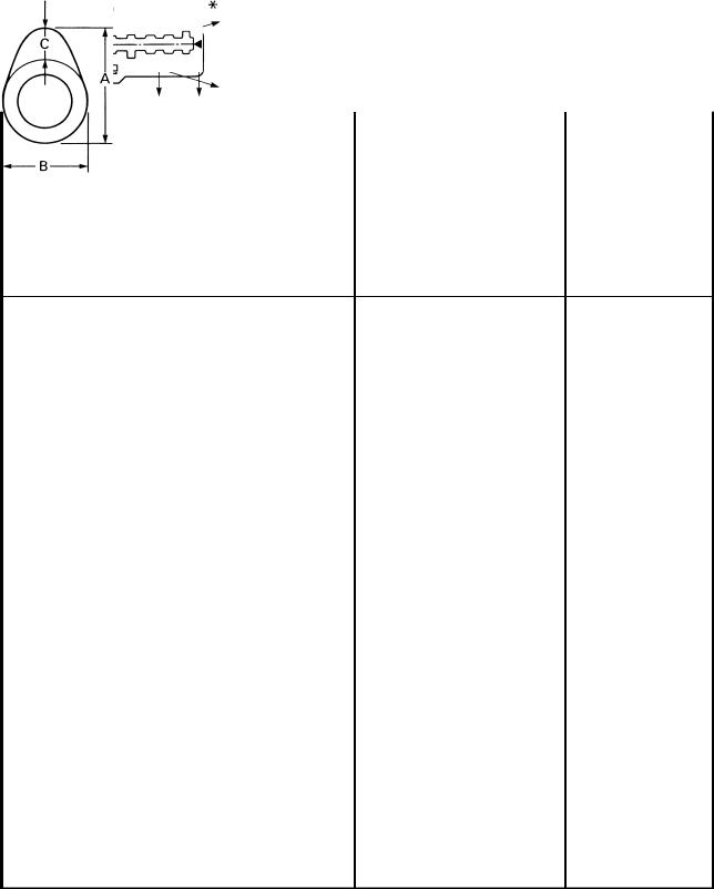
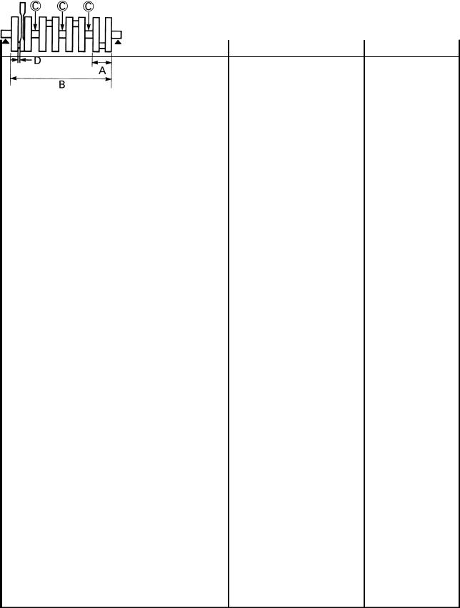
Cam dimensions |
|
|
Intake |
ªAº |
35.95 36.05 mm |
35.85 mm |
|
ªBº |
28.248 28.348 mm |
28.15 mm |
|
ªCº |
7.95 8.05 mm |
|
Exhaust |
ªAº |
35.95 36.05 mm |
35.85 mm |
|
ªBº |
28.248 28.348 mm |
28.15 mm |
|
ªCº |
7.95 8.05 mm |
|
Camshaft runout limit |
|
0.03 mm |
|
2-4
|
MAINTENANCE SPECIFICATIONS |
SPEC |
|
|
|
|
|
|
|
|
|
|
|
|
Model |
|
Standard |
Limit |
|
|
|
|
|
|
Cam chain: |
|
|
|
|
Cam chain type/No. of links |
79RH2015/156 |
|
|
|
Cam chain adjustment method |
Automatic |
|
|
|
|
|
|
|
|
Valve, valve seat, valve guide: |
|
|
|
|
Valve clearance (cold) |
IN |
0.11 0.15 mm |
|
|
|
EX |
0.16 0.20 mm |
|
|
Valve dimensions: |
|
|
|
|
Head Dia. |
Face Width |
Seat Width |
Margin Thickness |
|
ªAº head diameter |
IN |
28.9 29.1 mm |
|
|
|
EX |
24.9 25.1 mm |
|
|
ªBº face width |
IN |
1.98 2.55 mm |
|
|
|
EX |
1.98 2.55 mm |
|
|
ªCº seat width |
IN |
0.9 1.1 mm |
|
|
|
EX |
0.9 1.1 mm |
|
|
ªDº margin thickness |
IN |
0.8 1.2 mm |
|
|
|
EX |
0.8 1.2 mm |
|
|
Stem outside diameter |
IN |
5.475 5.490 mm |
5.445 mm |
|
|
EX |
5.460 5.475 mm |
5.43 mm |
|
Guide inside diameter |
IN |
5.500 5.512 mm |
5.552 mm |
|
|
EX |
5.500 5.512 mm |
5.552 mm |
|
Stem-to-guide clearance |
IN |
0.010 0.037 mm |
0.08 mm |
|
|
EX |
0.025 0.052 mm |
0.1 mm |
|
Stem runout limit |
|
|
|
0.01 mm |
Valve seat width |
IN |
0.9 1.1 mm |
1.6 mm |
|
EX |
0.9 1.1 mm |
1.6 mm |
2-5
MAINTENANCE SPECIFICATIONS |
SPEC |
|
|||
|
|
|
|
|
|
|
|
|
|
||
Model |
|
Standard |
Limit |
||
|
|
|
|
|
|
Valve spring: |
|
|
|
|
|
Inner spring |
|
|
|
|
|
Free length |
IN |
39.65 mm |
37.5 mm |
||
|
EX |
39.65 mm |
37.5 mm |
||
Set length (valve closed) |
IN |
32.8 mm |
|
|
|
|
EX |
32.8 mm |
|
|
|
Compressed pressure (installed) |
IN |
61.7 72.5 N (6.29 7.39 kg) |
|
|
|
|
EX |
61.7 72.5 N (6.29 7.39 kg) |
|
|
|
Tilt limit |
IN |
|
|
2.5 /1.7 mm |
|
|
EX |
|
|
2.5 /1.7 mm |
|
Direction of winding (top view) |
IN |
Clockwise |
|
|
EX |
Clockwise |
|
Outer spring |
|
|
|
Free length |
IN |
41.1 mm |
39 mm |
|
EX |
41.1 mm |
39 mm |
Set length (valve closed) |
IN |
34.8 mm |
|
|
EX |
34.8 mm |
|
Compressed pressure (installed) |
IN |
130.4 154.0 N (13.3 15.7 kg) |
|
|
EX |
130.4 154.0 N (13.3 15.7 kg) |
|
Tilt limit |
IN |
|
2.5 /1.7 mm |
|
EX |
|
2.5 /1.7 mm |
Direction of winding (top view) |
IN |
Counterclockwise |
|
|
EX |
Counterclockwise |
|
|
|
|
|
Piston: |
|
|
|
Piston to cylinder clearance |
|
0.015 0.040 mm |
0.15 mm |
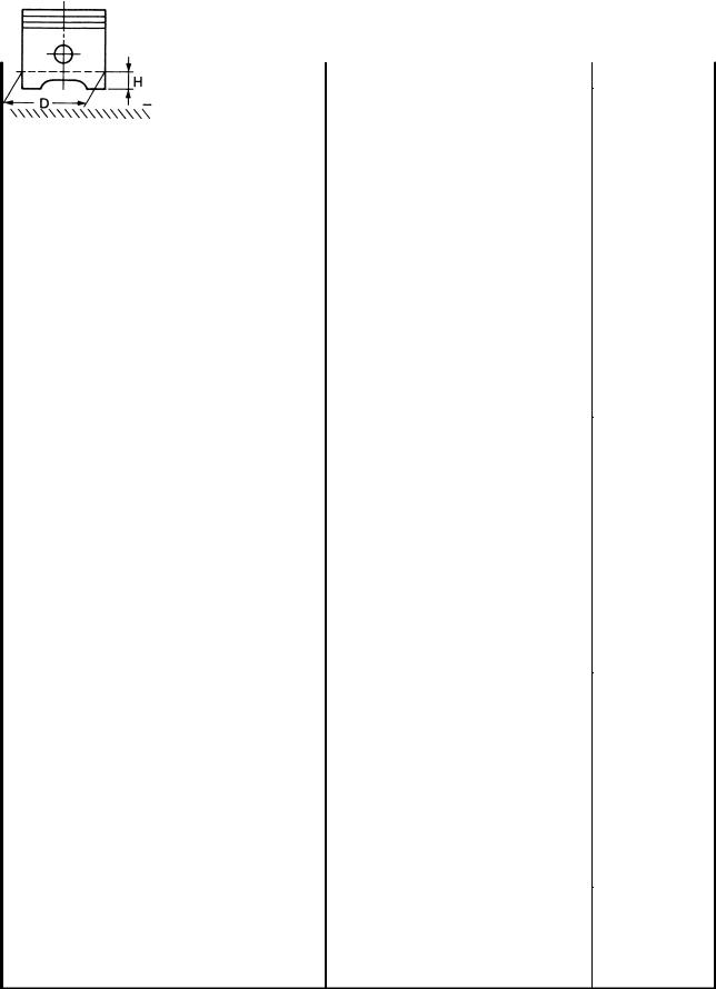
Piston size ªDº |
|
78.970 78.985 mm |
|
Measuring point ªHº |
2 mm |
|
Piston off-set |
1 mm |
|
Piston off-set direction |
IN side |
|
Piston pin bore inside diameter |
18.004 18.015 mm |
|
Piston pin outside diameter |
17.991 18.000 mm |
|
2-6
|
MAINTENANCE SPECIFICATIONS |
|
SPEC |
|
|
|
|
|
|
|
|
|
|
|
Model |
Standard |
|
Limit |
|
Piston rings:
Top ring:
Type |
Barrel |
|
Dimensions (B T) |
1.00 3.05 mm |
|
End gap (installed) |
0.20 0.35 mm |
0.6 mm |
Side clearance (installed) |
0.045 0.080 mm |
0.1 mm |
2nd ring:
Type |
Taper |
|
Dimensions (B T) |
1.2 3.0 mm |
|
End gap (installed) |
0.35 0.50 mm |
0.75 mm |
Side clearance (installed) |
0.03 0.07 mm |
0.1 mm |
Oil ring:
Dimensions (B T) |
2.5 2.9 mm |
|
End gap (installed) |
0.2 0.5 mm |
|
Side clearance |
0.050 0.155 mm |
|
|
|
|
Connecting rod: |
|
|
Oil clearance |
0.017 0.040 mm |
0.08 mm |
|
|
|
Crankshaft: |
|
|
Crank width ªAº |
62.25 63.85 mm |
|
Assembly width ªBº |
382.0 383.2 mm |
|
Runout limit ªCº |
0.02 mm |
|
Big end side clearance ªDº |
0.160 0.262 mm |
0.5 mm |
Journal oil clearance |
0.030 0.064 mm |
0.09 mm |
2-7
|
MAINTENANCE SPECIFICATIONS |
SPEC |
|
|
|
|
|
|
|
|
|
|
|
|
Model |
|
Standard |
Limit |
|
|
|
|
|
|
Clutch: |
|
|
|
|
Friction plate thickness |
|
2.9 3.1 mm |
2.8 mm |
|
Quantity |
|
8 pcs |
|
|
Clutch plate thickness |
|
1.9 2.1 mm |
0.1 mm |
|
|
|
|
<Warp limit> |
|
Quantity |
|
7 pcs |
|
|
Clutch spring height |
|
6 mm |
|
|
Quantity |
|
1 pc |
|
|
Clutch housing thrust clearance |
0 0.2 mm |
|
|
|
Clutch housing radial clearance |
0.004 0.048 mm |
0.1 mm |
||
Clutch release method |
|
Hydraulic inner push |
|
|
Push rod bending limit |
|
|
0.3 mm |
|
|
|
|
|
|
Transmission: |
|
|
|
|
Main axle deflection limit |
|
|
0.06 mm |
|
Drive axle deflection limit |
|
|
0.06 mm |
|
|
|
|
|
|
Shifter: |
|
|
|
|
Shifter type |
|
Guide bar |
|
|
Guide bar bending limit |
|
|
0.1 mm |
|
|
|
|
|
|
Carburetor: |
|
|
|
|
I.D. mark |
|
5EA1 10 |
|
|
Main jet |
(M.J) |
#95 |
|
|
Main air jet |
(M.A.J) |
#45 |
|
|
Jet needle |
(J.N) |
5D96-2 |
|
|
Needle jet |
(N.J) |
Y-2 |
|
|
Pilot jet |
(P.A.J.1) |
#127.5 |
|
|
Pilot outlet |
(P.O) |
0.85 |
|
|
Pilot jet |
(P.J) |
#40 |
|
|
Bypass 1 |
(B.P.1) |
0.9 |
|
|
Bypass 2 |
(B.P.2) |
1.0 |
|
|
Bypass 3 |
(B.P.3) |
0.8 |
|
|
Pilot screw |
(P.S) |
1-1/2 |
|
|
Valve seat size |
(V.S) |
2.3 |
|
|
Starter jet |
(G.S.1) |
#32.5 |
|
|
Starter jet |
(G.S.2) |
0.6 |
|
|
Throttle valve size |
(Th.V) |
#125 |
|
|
Float height |
(F.H) |
21.3 23.3 mm |
|
|
Fuel level (using special tool) |
3.5 4.5 mm |
|
|
|
Engine idle speed |
|
1000 1100 r/min |
|
|
Intake vacuum |
|
31.3 kPa (235 mmHg) |
|
|
2-8

MAINTENANCE SPECIFICATIONS |
|
SPEC |
|
||
|
|
|
|
|
|
|
|
|
|
|
|
Model |
Standard |
|
|
Limit |
|
|
|
|
|
|
|
Lubrication system: |
|
|
|
|
|
Oil filter type |
Paper type |
|
|
|
|
Oil pump type |
Trochoid type |
|
|
|
|
Tip clearance |
0.12 0.17 mm |
|
|
0.2 mm |
|
Housing and rotor clearance |
0.03 0.08 mm |
|
|
0.15 mm |
|
Side clearance |
0.03 0.08 mm |
|
|
0.15 mm |
|
Bypass valve setting pressure |
180 220 kPa |
|
|
|
|
|
(1.8 2.2 kg/cm2, 1.8 2.2 bar) |
|
|
|
|
Relief valve operating pressure |
480 580 kPa |
|
|
|
|
|
(4.8 5.8 kg/cm2, 4.8 5.8 bar) |
|
|
|
|
Oil pressure (hot) |
80 kPa (0.8 kg/cm2, 0.8 bar) |
|
|
|
|
|
at 1000 r/min |
|
|
|
|
Pressure check location |
MAIN GALLERY |
|
|
|
|
2-9
MAINTENANCE SPECIFICATIONS |
|
|
|
SPEC |
|
||||||
Tightening torques |
|
|
|
|
|
|
|
|
|
|
|
|
|
|
|
|
|
|
|
|
|
|
|
|
|
|
|
|
|
|
|
|
|||
|
|
Thread |
|
Tightening |
|
|
|||||
Part to be tightened |
Part name |
Q'ty |
|
torque |
Remarks |
||||||
size |
|
||||||||||
|
|
|
Nm |
|
|
m kg |
|
|
|||
|
|
|
|
|
|
|
|
|
|||
Camshaft cap |
Bolt |
M6 |
1.0 |
18 |
|
12 |
|
|
1.2 |
|
|
Oil gallery bolt |
Screw |
M6 |
1.0 |
1 |
|
7 |
|
0.7 |
|
|
|
Spark plug |
± |
M12 |
1.25 |
4 |
|
18 |
|
1.8 |
|
|
|
Cylinder head |
Cap nut |
M10 |
1.25 |
12 |
|
35 |
|
3.5 |
|
|
|
Cylinder head cover |
Bolt |
M6 |
1.0 |
8 |
|
10 |
|
1.0 |
|
|
|
Cylinder |
Stud bolt |
M8 1.25 |
1 |
|
8 |
|
0.8 |
|
|
||
Cylinder |
Nut |
M8 1.25 |
3 |
|
20 |
|
2.0 |
|
|
||
Cylinder |
Nut |
M6 |
1.0 |
6 |
|
10 |
|
1.0 |
|
|
|
Connecting rod |
Nut |
M8 0.75 |
8 |
|
36 |
|
3.6 |
|
|
||
Cam sprocket |
Bolt |
M7 |
1.0 |
4 |
|
20 |
|
2.0 |
|
|
|
Timing chain tensioner |
Bolt |
M6 |
1.0 |
2 |
|
10 |
|
1.0 |
|
|
|
Timing chain tensioner cap bolt |
Bolt |
M11 1.0 |
1 |
|
20 |
|
2.0 |
|
|
||
Chain guide (upper) |
Bolt |
M6 |
1.0 |
4 |
|
10 |
|
1.0 |
|
|
|
Chain guide (intake) |
Plug |
M10 |
1.25 |
1 |
|
10 |
|
1.0 |
|
|
|
Oil pump |
Screw |
M6 |
1.0 |
2 |
|
10 |
|
1.0 |
|
|
|
Oil pump |
Bolt |
M6 |
1.0 |
3 |
|
10 |
|
1.0 |
|
|
|
Oil strainer housing |
Bolt |
M6 |
1.0 |
2 |
|
10 |
|
1.0 |
|
|
|
Oil filter case |
Union bolt |
M20 1.5 |
1 |
|
15 |
|
1.5 |
|
|
||
Oil pan |
Bolt |
M6 |
1.0 |
17 |
|
10 |
|
1.0 |
|
|
|
Drain bolt (engine oil) |
Plug |
M14 1.5 |
1 |
|
43 |
|
4.3 |
|
|
||
Oil gallery blind plug |
Plug |
M16 1.5 |
1 |
|
8 |
|
0.8 |
|
|
||
Drain filter |
Screw |
M5 |
0.8 |
1 |
|
7 |
|
0.7 |
|
|
|
Oil delivery pipe (oil pan) |
Bolt |
M6 |
1.0 |
4 |
|
10 |
|
1.0 |
|
|
|
Oil delivery pipe (oil cooler) |
Bolt |
M6 |
1.0 |
4 |
|
10 |
|
1.0 |
|
|
|
Oil cooler |
Bolt |
M6 |
1.0 |
2 |
|
10 |
|
1.0 |
|
|
|
Oil cooler cover |
Bolt |
M6 |
1.0 |
4 |
|
8 |
|
0.8 |
|
|
|
Oil delivery pipe (clamp) |
Bolt |
M6 |
1.0 |
1 |
|
10 |
|
1.0 |
|
|
|
Intake manifold |
Bolt |
M6 |
1.0 |
8 |
|
10 |
|
1.0 |
|
|
|
Air filter case cap |
Bolt |
M5 |
0.8 |
4 |
|
5 |
|
0.5 |
|
|
|
Air filter case |
Bolt |
M6 |
1.0 |
3 |
|
7 |
|
0.7 |
|
|
|
Exhaust pipe |
Nut |
M8 1.25 |
8 |
|
25 |
|
2.5 |
|
|
||
Muffler and stay |
Bolt |
M8 1.25 |
2 |
|
20 |
|
2.0 |
|
|
||
Exhaust chamber |
Bolt |
M10 |
1.25 |
1 |
|
25 |
|
2.5 |
|
|
|
Exhaust pipe and exhaust chamber |
Screw |
M8 1.25 |
4 |
|
20 |
|
2.0 |
|
|
||
Exhaust chamber and muffler |
Bolt |
M8 1.25 |
2 |
|
20 |
|
2.0 |
|
|
||
Exhaust pipe blind plug (CO test) |
Bolt |
M6 |
1.0 |
4 |
|
10 |
|
1.0 |
|
|
|
Bearing holder (main axle) |
Screw |
M6 |
1.0 |
3 |
|
12 |
|
1.2 |
|
|
|
Timing plate cover |
Bolt |
M6 |
1.0 |
4 |
|
7 |
|
0.7 |
|
|
|
Crankcase cover (right) |
Screw |
M5 |
0.8 |
2 |
|
4 |
|
0.4 |
|
|
|
Clutch cover |
Bolt |
M6 |
1.0 |
11 |
|
10 |
|
1.0 |
|
|
|
Drive sprocket cover |
Bolt |
M6 |
1.0 |
3 |
|
10 |
|
1.0 |
|
|
|
Clutch release cylinder |
Bolt |
M6 |
1.0 |
3 |
|
10 |
|
1.0 |
|
|
|
Crankcase |
Bolt |
M6 |
1.0 |
16 |
|
12 |
|
1.2 |
|
|
|
|
|
|
|
|
|
|
|
|
|
|
|
2-10
MAINTENANCE SPECIFICATIONS |
|
|
|
SPEC |
|
||||||
|
|
|
|
|
|
|
|
|
|
|
|
|
|
|
|
|
|
|
|
|
|||
|
|
Thread |
|
Tightening |
|
|
|||||
Part to be tightened |
Part name |
Q'ty |
|
torque |
Remarks |
||||||
size |
|
||||||||||
|
|
|
Nm |
|
|
m kg |
|
|
|||
|
|
|
|
|
|
|
|
|
|||
Crankcase |
Bolt |
M8 1.25 |
17 |
|
24 |
|
|
2.4 |
|
|
|
Crankcase |
Bolt |
M10 |
1.25 |
5 |
|
35 |
|
3.5 |
|
|
|
Main gallery |
Plug |
M20 1.5 |
3 |
|
12 |
|
1.2 |
|
|
||
Oil buffle plate |
Bolt |
M5 |
0.8 |
3 |
|
4 |
|
0.4 |
|
|
|
Stopper plate |
Bolt |
M6 |
1.0 |
1 |
|
10 |
|
1.0 |
|
|
|
Bearing housing |
Screw |
M6 |
1.0 |
3 |
|
10 |
|
1.0 |
|
|
|
HY-VO chain guide |
Bolt |
M6 |
1.0 |
2 |
|
10 |
|
1.0 |
|
|
|
Clutch boss |
Nut |
M20 1.5 |
1 |
|
70 |
|
7.0 |
|
|
||
Clutch pressure plate |
Bolt |
M6 |
1.0 |
6 |
|
8 |
|
0.8 |
|
|
|
Push lever comp. |
Bolt |
M6 |
1.0 |
2 |
|
10 |
|
1.0 |
|
|
|
Drive sprocket |
Nut |
M22 1.5 |
1 |
|
85 |
|
8.5 |
|
|
||
Shift shaft stopper |
Screw |
M8 1.25 |
1 |
|
22 |
|
2.2 |
|
|
||
Stopper plate |
Screw |
M6 |
1.0 |
2 |
|
7 |
|
0.7 |
|
|
|
(Starter clutch idle gear shaft) |
|
|
|
|
|
|
|
|
|
|
|
Stopper lever |
Bolt |
M6 |
1.0 |
1 |
|
10 |
|
1.0 |
|
|
|
Side plate |
Screw |
M5 |
0.8 |
1 |
|
4 |
|
0.4 |
|
|
|
Shift arm |
Bolt |
M6 |
1.0 |
1 |
|
10 |
|
1.0 |
|
|
|
Shift lod |
Nut |
M6 |
1.0 |
2 |
|
8 |
|
0.8 |
|
|
|
A.C. generator |
Bolt |
M8 1.25 |
2 |
|
25 |
|
2.5 |
|
|
||
Oil level sensor |
Bolt |
M6 |
1.0 |
2 |
|
10 |
|
1.0 |
|
|
|
Rotor |
Bolt |
M10 |
1.25 |
1 |
|
45 |
|
4.5 |
|
|
|
2-11
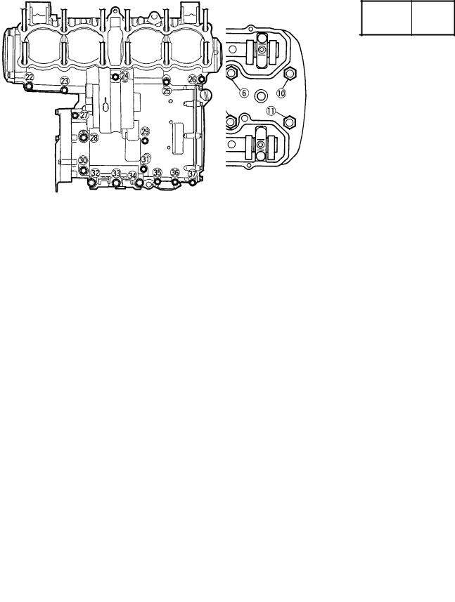
MAINTENANCE SPECIFICATIONS SPEC 
Tightening sequence
Cylinder head
Crankcase
2-12
|
MAINTENANCE SPECIFICATIONS |
SPEC |
|
||
|
|
|
|
|
|
|
|
|
|||
Model |
|
XJR1300(L) |
|||
|
|
|
|
|
|
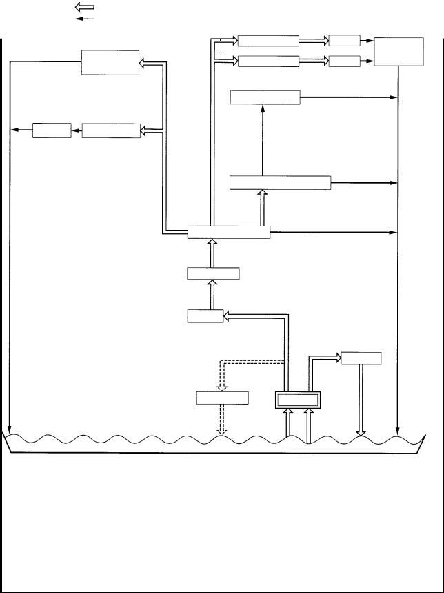
Lubrication chart:
Pressure feed
Splashed
|
|
Ex. camshaft |
Lifter |
Timing |
|
|
|
|
|
|
Generator |
IN. camshaft |
Lifter |
chain area |
|
shaft |
|
||
|
|
|
|
|
|
|
Piston, Cylinder |
|
|
Clutch |
Transmission |
|
|
|
Connecting rod bearing
Crankshaft bearings
Main gallery
Oil filter
Oil cooler
Relief valve |
Oil pump |
Oil pan/Oil strainer
2-13

|
|
MAINTENANCE SPECIFICATIONS |
SPEC |
|
|
|
CHASSIS |
|
|
|
|
|
|
|
|
|
|
|
|
|
|
|
|
|
|
|
|
|
Model |
Standard |
|
Limit |
|
|
|
|
|
|
|
|
|
Steering system: |
|
|
|
|
|
|
Steering bearing type |
Angular bearing |
|
|
|
||
|
|
|
|
|
|
|
Front suspension: |
|
|
|
|
|
|
Front fork travel |
|
130 mm |
|
|
|
|
Fork spring free length |
407.3 mm |
395 mm |
|
|||
Fitting length |
|
|
363.3 mm |
|
|
|
Collar length |
|
|
150 mm |
|
|
|
Spring rate |
(K1) |
|
4.9 N/mm (0.5 kg/mm) |
|
|
|
|
(K2) |
|
8.8 N/mm (0.9 kg/mm) |
|
|
|
Stroke |
(K1) |
|
0 83 mm |
|
|
|
|
(K2) |
|
83 130 mm |
|
|
|
Optional spring |
|
No |
|
|
|
|
Oil capacity |
|
|
538 cm3 |
|
|
|
Oil level |
|
|
137 mm |
|
|
|
Oil grade |
|
|
Fork oil 10W or equivalent |
|
|
|
|
|
|
|
|
|
|
Rear suspension: |
|
|
|
|
|
|
Shock absorber travel |
88 mm |
|
|
|
||
Spring free length |
|
210 mm |
206 mm |
|
||
Fitting length |
|
|
190 mm |
|
|
|
Spring rate |
(K1) |
|
20.6 N/mm (2.1 kg/mm) |
|
|
|
|
(K2) |
|
31.4 N/mm (3.2 kg/mm) |
|
|
|
Stroke |
(K1) |
|
0 50 mm |
|
|
|
|
(K2) |
|
50 88 mm |
|
|
|
|
|
|
|
|
|
|
Front wheel: |
|
|
|
|
|
|
Type |
|
|
Cast wheel |
|
|
|
Rim size |
|
|
17 MT3.50 |
|
|
|
Rim material |
|
|
Aluminum |
|
|
|
Rim runout limit |
radial |
|
1 mm |
|
||
|
|
lateral |
|
0.5 mm |
|
|
|
|
|
|
|
|
|
Rear wheel: |
|
|
|
|
|
|
Type |
|
|
Cast wheel |
|
|
|
Rim size |
|
|
17 MT5.50 |
|
|
|
Rim material |
|
|
Aluminum |
|
|
|
Rim runout limit |
radial |
|
1 mm |
|
||
|
|
lateral |
|
0.5 mm |
|
|
|
|
|
|
|
|
|
Drive chain: |
|
|
|
|
|
|
Type/manufacturer |
|
50ZVM/DAIDO |
|
|
|
|
No. of links |
|
|
110 |
|
|
|
Chain free play |
|
20 30 mm |
|
|
|
|
|
|
|
|
|
|
|
2-14
 Loading...