


XVS1100 (A) (AA) 2011
XVS1100A
XVS1100AA
OWNER’S MANUAL
Read this manual carefully before operating this vehicle.
3B8-28199-25

EAU46090
Read this manual carefully before operating this vehicle. This manual should stay with this vehicle if it is sold.
INTRODUCTION
EAU10102
Welcome to the Yamaha world of motorcycling!
As the owner of the XVS1100A/XVS1100AA, you are benefiting from Yamaha’s vast experience and newest technology re-
garding the design and manufacture of high-quality products, which have earned Yamaha a reputation for dependability.
Please take the time to read this manual thoroughly, so as to enjoy all advantages of your XVS1100A/XVS1100AA. The
Owner’s Manual does not only instruct you in how to operate, inspect and maintain your motorcycle, but also in how to safe-
guard yourself and others from trouble and injury.
In addition, the many tips given in this manual will help keep your motorcycle in the best possible condition. If you have any
further questions, do not hesitate to contact your Yamaha dealer.
The Yamaha team wishes you many safe and pleasant rides. So, remember to put safety first!
Yamaha continually seeks advancements in product design and quality. Therefore, while this manual contains the most cur-
rent product information available at the time of printing, there may be minor discrepancies between your motorcycle and this
manual. If there is any question concerning this manual, please consult a Yamaha dealer.
WARNING
EWA10031
Please read this manual carefully and completely before operating this motorcycle.
IMPORTANT MANUAL INFORMATION
EAU10132
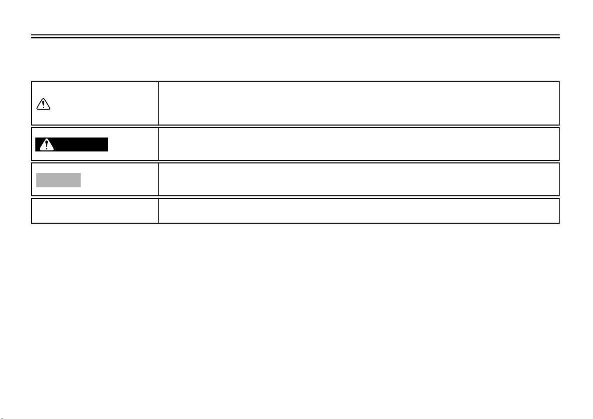
Particularly important information is distinguished in this manual by the following notations:
This is the safety alert symbol. It is used to alert you to potential personal injury
hazards. Obey all safety messages that follow this symbol to avoid possible injury
or death.
A WARNING indicates a hazardous situation which, if not avoided, could result in
death or serious injury.
A NOTICE indicates special precautions that must be taken to avoid damage to the
vehicle or other property.
A TIP provides key information to make procedures easier or clearer.
WARNING
NOTICE
TIP
IMPORTANT MANUAL INFORMATION
EAU10200
XVS1100A/XVS1100AA
OWNER’S MANUAL
©2010 by Yamaha Motor Co., Ltd.
1st edition, June 2010
All rights reserved.
Any reprinting or unauthorized use
without the written permission of
Yamaha Motor Co., Ltd.
is expressly prohibited.
Printed in Japan.

TABLE OF CONTENTS
LOCATION OF IMPORTANT
LABELS .............................................1-1
SAFETY INFORMATION ..................2-1
DESCRIPTION ..................................3-1
Left view ..........................................3-1
Right view........................................3-3
Controls and instruments.................3-5
INSTRUMENT AND CONTROL
FUNCTIONS .......................................4-1
Immobilizer system
(XVS1100AA) ..............................4-1
Main switch/steering lock
(XVS1100A) ................................4-2
Main switch/steering lock
(XVS1100AA) ..............................4-2
Indicator lights and warning
lights ............................................4-4
Speedometer unit ...........................4-6
Self-diagnosis device ......................4-6
Handlebar switches ........................4-7
Clutch lever .....................................4-8
Shift pedal (XVS1100A) ..................4-8
Shift pedal (XVS1100AA) ...............4-9
Brake lever .....................................4-9
Brake pedal ....................................4-9
Fuel tank cap ................................4-10
Fuel ...............................................4-10
Fuel cock ......................................4-11
Starter (choke) lever ..................... 4-12
Seats (XVS1100A) .......................4-13
Seats (XVS1100AA) .....................4-14
Helmet holder ............................... 4-15
Storage compartment ................... 4-16
Adjusting the shock absorber
assembly ...................................4-17
Luggage strap holders ................. 4-19
Sidestand .....................................4-19
Ignition circuit cut-off system ........ 4-20
FOR YOUR SAFETY –
PRE-OPERATION CHECKS .............5-1
OPERATION AND IMPORTANT
RIDING POINTS.................................6-1
Starting and warming up a cold
engine .........................................6-1
Starting a warm engine .................. 6-2
Shifting ...........................................6-2
Tips for reducing fuel
consumption ...............................6-3
Engine break-in ..............................6-4
Parking ...........................................6-4
PERIODIC MAINTENANCE AND
ADJUSTMENT ................................... 7-1
Owner’s tool kit ...............................7-2
Periodic maintenance chart for the
emission control system ............. 7-3
General maintenance and
lubrication chart .......................... 7-4
Removing and installing the
panel ........................................... 7-8
Checking the spark plugs .............. 7-8
Engine oil ..................................... 7-10
Final gear oil ................................ 7-11
Cleaning the air filter element ...... 7-13
Adjusting the carburetors ............. 7-14
Adjusting the engine idling
speed ........................................ 7-14
Checking the throttle grip free
play ........................................... 7-15
Valve clearance ........................... 7-15
Tires (XVS1100A) ........................ 7-15
Tires (XVS1100AA) ..................... 7-17
Spoke wheels (XVS1100A) ......... 7-19
Cast wheels (XVS1100AA) .......... 7-19
Adjusting the clutch lever free
play ........................................... 7-20
Adjusting the brake lever free
play ........................................... 7-21
Brake light switches ..................... 7-22
Checking the front and rear brake
pads .......................................... 7-22
Checking the brake fluid level ...... 7-23
Changing the brake fluid .............. 7-24
Checking and lubricating the
cables ....................................... 7-24
Checking and lubricating the
throttle grip and cable ............... 7-24

TABLE OF CONTENTS
Checking and lubricating the
brake and shift pedals ...............7-25
Checking and lubricating the
brake and clutch levers .............7-25
Checking and lubricating the
sidestand ...................................7-26
Lubricating the swingarm pivots ...7-26
Lubricating the rear suspension ...7-27
Checking the front fork .................7-27
Checking the steering ...................7-28
Checking the wheel bearings .......7-28
Battery ..........................................7-28
Replacing the fuses ......................7-30
Replacing the headlight bulb ........7-31
Replacing a turn signal light bulb
or the tail/brake light bulb ..........7-33
Replacing the auxiliary light bulb
(XVS1100AA) ............................7-33
Supporting the motorcycle ............7-34
Troubleshooting ............................7-35
Troubleshooting chart ...................7-36
MOTORCYCLE CARE AND
STORAGE ..........................................8-1
Matte color caution .........................8-1
Care ................................................8-1
Storage ...........................................8-3
SPECIFICATIONS ............................ 9-1
CONSUMER INFORMATION .......... 10-1
Identification numbers .................. 10-1
Motorcycle noise regulation (for
Australia) .................................. 10-2
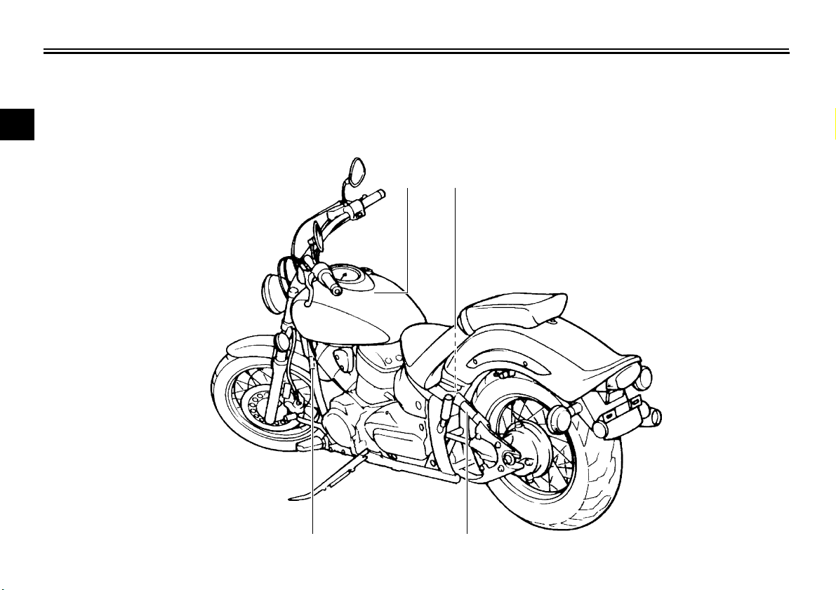
LOCATION OF IMPORTANT LABELS
1-1
1
EAU10384
Read and understand all of the labels on your vehicle. They contain important information for safe and proper operation of
your vehicle. Never remove any labels from your vehicle. If a label becomes difficult to read or comes off, a replacement label
is available from your Yamaha dealer.
12
34
LOCATION OF IMPORTANT LABELS
1-2
1
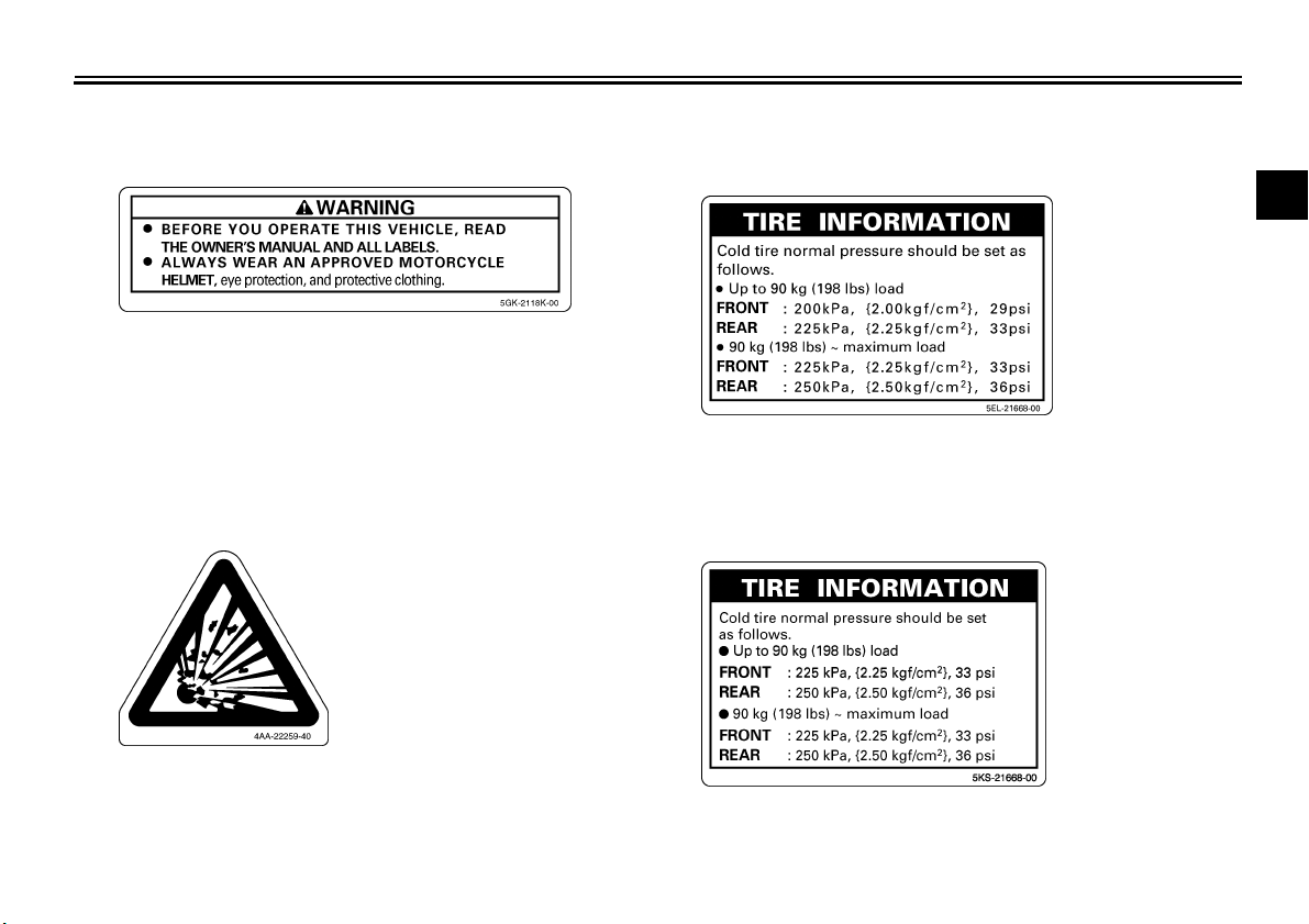
3 XVS1100A1
2 3 XVS1100AA
LOCATION OF IMPORTANT LABELS
1-3
1
4
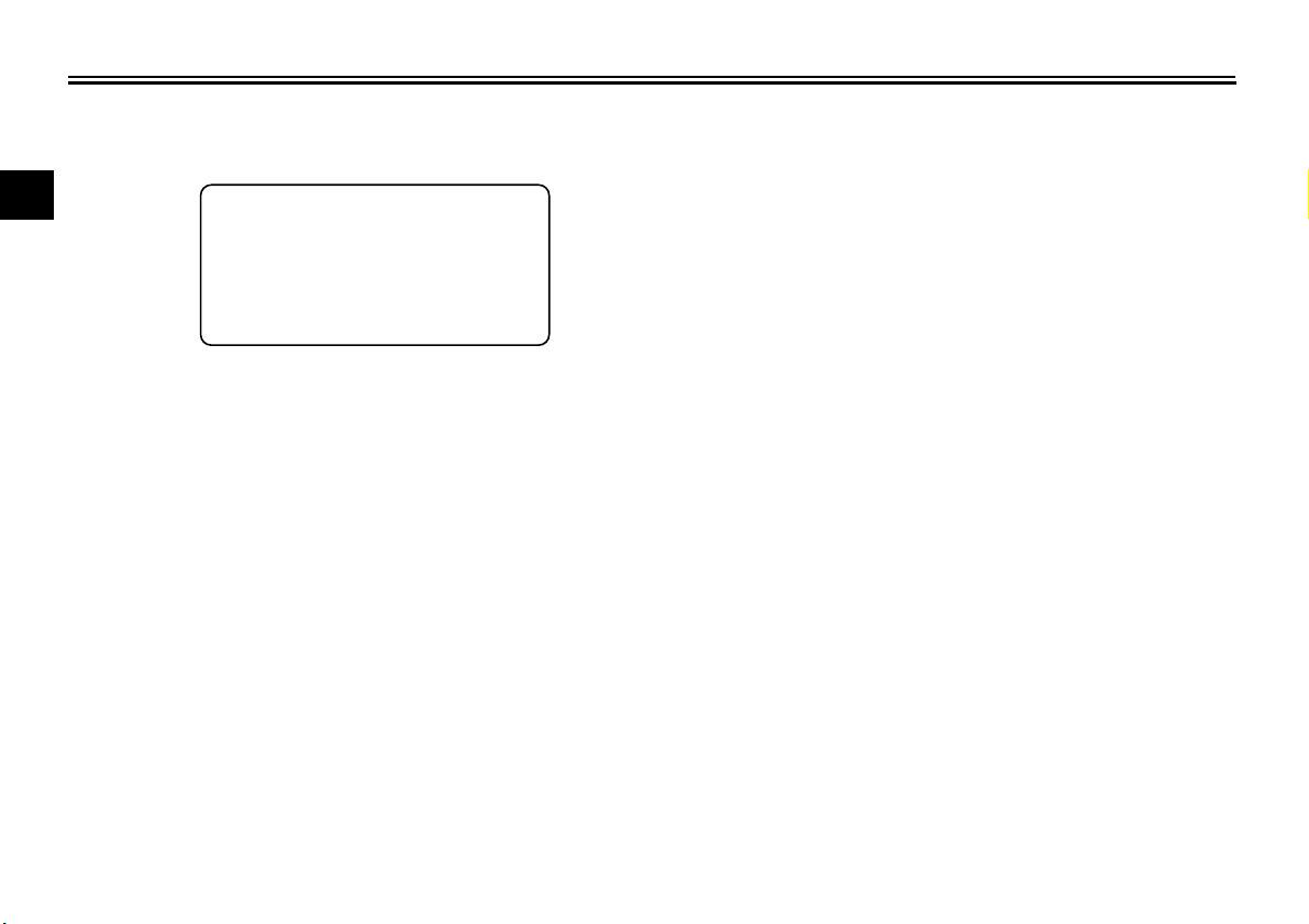
STATIONARY NOISE TEST INFORMATION
TESTED 85.0 dB(A) AT 2875 r/min
SILENCING SYSTEM : YAMAHA
IDENTIFICATION :
5EL1
5EL-2118G-00

2-1
2
SAFETY INFORMATION
EAU10287
Be a Responsible Owner
As the vehicle’s owner, you are respon-
sible for the safe and proper operation
of your motorcycle.
Motorcycles are single-track vehicles.
Their safe use and operation are de-
pendent upon the use of proper riding
techniques as well as the expertise of
the operator. Every operator should
know the following requirements before
riding this motorcycle.
He or she should:
● Obtain thorough instructions from
a competent source on all aspects
of motorcycle operation.
● Observe the warnings and mainte-
nance requirements in this Own-
er’s Manual.
● Obtain qualified training in safe
and proper riding techniques.
● Obtain professional technical ser-
vice as indicated in this Owner’s
Manual and/or when made neces-
sary by mechanical conditions.
Safe Riding
Perform the pre-operation checks each
time you use the vehicle to make sure it
is in safe operating condition. Failure to
inspect or maintain the vehicle properly
increases the possibility of an accident
or equipment damage. See page 5-1
for a list of pre-operation checks.
● This motorcycle is designed to car-
ry the operator and a passenger.
● The failure of motorists to detect
and recognize motorcycles in traf-
fic is the predominating cause of
automobile/motorcycle accidents.
Many accidents have been caused
by an automobile driver who did
not see the motorcycle. Making
yourself conspicuous appears to
be very effective in reducing the
chance of this type of accident.
Therefore:
• Wear a brightly colored jacket.
• Use extra caution when you are
approaching and passing
through intersections, since in-
tersections are the most likely
places for motorcycle accidents
to occur.
• Ride where other motorists can
see you. Avoid riding in another
motorist’s blind spot.
● Many accidents involve inexperi-
enced operators. In fact, many op-
erators who have been involved in
accidents do not even have a cur-
rent motorcycle license.
• Make sure that you are qualified
and that you only lend your mo-
torcycle to other qualified opera-
tors.
• Know your skills and limits.
Staying within your limits may
help you to avoid an accident.
• We recommend that you prac-
tice riding your motorcycle
where there is no traffic until you
have become thoroughly famil-
iar with the motorcycle and all of
its controls.
● Many accidents have been caused
by error of the motorcycle opera-
tor. A typical error made by the op-
erator is veering wide on a turn

SAFETY INFORMATION
2-2
2
due to excessive speed or under-
cornering (insufficient lean angle
for the speed).
• Always obey the speed limit and
never travel faster than warrant-
ed by road and traffic conditions.
• Always signal before turning or
changing lanes. Make sure that
other motorists can see you.
● The posture of the operator and
passenger is important for proper
control.
• The operator should keep both
hands on the handlebar and
both feet on the operator foot-
rests during operation to main-
tain control of the motorcycle.
• The passenger should always
hold onto the operator, the seat
strap or grab bar, if equipped,
with both hands and keep both
feet on the passenger footrests.
Never carry a passenger unless
he or she can firmly place both
feet on the passenger footrests.
● Never ride under the influence of
alcohol or other drugs.
● This motorcycle is designed for on-
road use only. It is not suitable for
off-road use.
Protective Apparel
The majority of fatalities from motorcy-
cle accidents are the result of head in-
juries. The use of a safety helmet is the
single most critical factor in the preven-
tion or reduction of head injuries.
● Always wear an approved helmet.
● Wear a face shield or goggles.
Wind in your unprotected eyes
could contribute to an impairment
of vision that could delay seeing a
hazard.
● The use of a jacket, heavy boots,
trousers, gloves, etc., is effective in
preventing or reducing abrasions
or lacerations.
● Never wear loose-fitting clothes,
otherwise they could catch on the
control levers, footrests, or wheels
and cause injury or an accident.
● Always wear protective clothing
that covers your legs, ankles, and
feet. The engine or exhaust sys-
tem become very hot during or af-
ter operation and can cause burns.
● A passenger should also observe
the above precautions.
Avoid Carbon Monoxide Poisoning
All engine exhaust contains carbon
monoxide, a deadly gas. Breathing car-
bon monoxide can cause headaches,
dizziness, drowsiness, nausea, confu-
sion, and eventually death.
Carbon Monoxide is a colorless, odor-
less, tasteless gas which may be
present even if you do not see or smell
any engine exhaust. Deadly levels of
carbon monoxide can collect rapidly
and you can quickly be overcome and
unable to save yourself. Also, deadly
levels of carbon monoxide can linger
for hours or days in enclosed or poorly
ventilated areas. If you experience any
symptoms of carbon monoxide poison-
ing, leave the area immediately, get
fresh air, and SEEK MEDICAL TREAT-
MENT.
● Do not run engine indoors. Even if
you try to ventilate engine exhaust
with fans or open windows and
doors, carbon monoxide can rap-
idly reach dangerous levels.
SAFETY INFORMATION
2-3
2
● Do not run engine in poorly venti-
lated or partially enclosed areas
such as barns, garages, or car-
ports.
● Do not run engine outdoors where
engine exhaust can be drawn into
a building through openings such
as windows and doors.
Loading
Adding accessories or cargo to your
motorcycle can adversely affect stabili-
ty and handling if the weight distribution
of the motorcycle is changed. To avoid
the possibility of an accident, use ex-
treme caution when adding cargo or
accessories to your motorcycle. Use
extra care when riding a motorcycle
that has added cargo or accessories.
Here, along with the information about
accessories below, are some general
guidelines to follow if loading cargo to
your motorcycle:
The total weight of the operator, pas-
senger, accessories and cargo must
not exceed the maximum load limit.
Operation of an overloaded vehicle
could cause an accident.
When loading within this weight limit,
keep the following in mind:
● Cargo and accessory weight
should be kept as low and close to
the motorcycle as possible. Se-
curely pack your heaviest items as
close to the center of the vehicle as
possible and make sure to distrib-
ute the weight as evenly as possi-
ble on both sides of the motorcycle
to minimize imbalance or instabili-
ty.
● Shifting weights can create a sud-
den imbalance. Make sure that ac-
cessories and cargo are securely
attached to the motorcycle before
riding. Check accessory mounts
and cargo restraints frequently.
• Properly adjust the suspension
for your load (suspension-ad-
justable models only), and
check the condition and pres-
sure of your tires.
• Never attach any large or heavy
items to the handlebar, front
fork, or front fender. These
items, including such cargo as
sleeping bags, duffel bags, or
tents, can create unstable han-
dling or a slow steering re-
sponse.
● This vehicle is not designed to
pull a trailer or to be attached to
a sidecar.
Genuine Yamaha Accessories
Choosing accessories for your vehicle
is an important decision. Genuine
Yamaha accessories, which are avail-
able only from a Yamaha dealer, have
been designed, tested, and approved
by Yamaha for use on your vehicle.
Many companies with no connection to
Yamaha manufacture parts and acces-
sories or offer other modifications for
Yamaha vehicles. Yamaha is not in a
position to test the products that these
aftermarket companies produce.
Therefore, Yamaha can neither en-
dorse nor recommend the use of ac-
cessories not sold by Yamaha or
Maximum load:
XVS1100A 200 kg (441 lb)
XVS1100AA 203 kg (448 lb)

SAFETY INFORMATION
2-4
2
modifications not specifically recom-
mended by Yamaha, even if sold and
installed by a Yamaha dealer.
Aftermarket Parts, Accessories, and
Modifications
While you may find aftermarket prod-
ucts similar in design and quality to
genuine Yamaha accessories, recog-
nize that some aftermarket accessories
or modifications are not suitable be-
cause of potential safety hazards to you
or others. Installing aftermarket prod-
ucts or having other modifications per-
formed to your vehicle that change any
of the vehicle’s design or operation
characteristics can put you and others
at greater risk of serious injury or death.
You are responsible for injuries related
to changes in the vehicle.
Keep the following guidelines in mind,
as well as those provided under “Load-
ing” when mounting accessories.
● Never install accessories or carry
cargo that would impair the perfor-
mance of your motorcycle. Care-
fully inspect the accessory before
using it to make sure that it does
not in any way reduce ground
clearance or cornering clearance,
limit suspension travel, steering
travel or control operation, or ob-
scure lights or reflectors.
• Accessories fitted to the handle-
bar or the front fork area can
create instability due to improper
weight distribution or aerody-
namic changes. If accessories
are added to the handlebar or
front fork area, they must be as
lightweight as possible and
should be kept to a minimum.
• Bulky or large accessories may
seriously affect the stability of
the motorcycle due to aerody-
namic effects. Wind may at-
tempt to lift the motorcycle, or
the motorcycle may become un-
stable in cross winds. These ac-
cessories may also cause
instability when passing or being
passed by large vehicles.
• Certain accessories can dis-
place the operator from his or
her normal riding position. This
improper position limits the free-
dom of movement of the opera-
tor and may limit control ability,
therefore, such accessories are
not recommended.
● Use caution when adding electri-
cal accessories. If electrical acces-
sories exceed the capacity of the
motorcycle’s electrical system, an
electric failure could result, which
could cause a dangerous loss of
lights or engine power.
Aftermarket Tires and Rims
The tires and rims that came with your
motorcycle were designed to match the
performance capabilities and to provide
the best combination of handling, brak-
ing, and comfort. Other tires, rims, siz-
es, and combinations may not be
appropriate. Refer to page 7-15 for tire
specifications and more information on
replacing your tires.
Transporting the Motorcycle
Be sure to observe following instruc-
tions before transporting the motorcy-
cle in another vehicle.
● Remove all loose items from the
motorcycle.
SAFETY INFORMATION
2-5
2
● Check that the fuel cock (if
equipped) is in the “OFF” position
and that there are no fuel leaks.
● Point the front wheel straight
ahead on the trailer or in the truck
bed, and choke it in a rail to pre-
vent movement.
● Shift the transmission in gear (for
models with a manual transmis-
sion).
● Secure the motorcycle with tie-
downs or suitable straps that are
attached to solid parts of the mo-
torcycle, such as the frame or up-
per front fork triple clamp (and not,
for example, to rubber-mounted
handlebars or turn signals, or parts
that could break). Choose the lo-
cation for the straps carefully so
the straps will not rub against
painted surfaces during transport.
● The suspension should be com-
pressed somewhat by the tie-
downs, if possible, so that the mo-
torcycle will not bounce excessive-
ly during transport.
DESCRIPTION
3-1
3
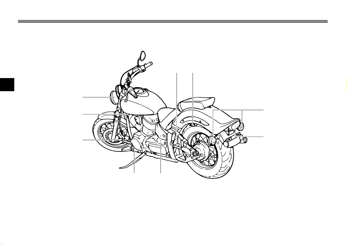
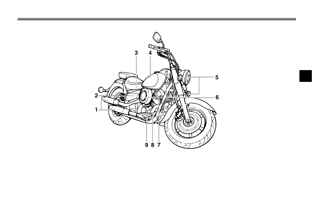
EAU32220
Left view
XVS1100A
4
3
6
7
2
1
5
11 8,9,10
1. Shift pedal (page 4-8)
2. Fuel cock (page 4-11)
3. Headlight (page 7-31)
4. Shock absorber assembly spring preload adjusting ring (page 4-17)
5. Helmet holder (page 4-15)
6. Rear turn signal light (page 7-33)
7. Tail/brake light (page 7-33)
8. Storage compartment (page 4-16)
9. Owner’s tool kit (page 7-2)
10.Fuse box (page 7-30)
11.Engine oil level check window (page 7-10)
DESCRIPTION
3-2
3
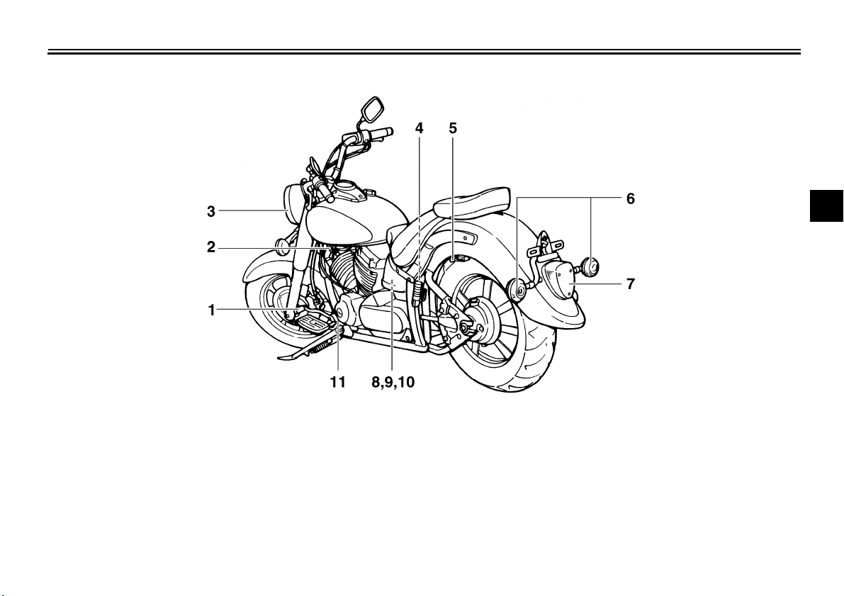
XVS1100AA
1. Shift pedal (page 4-8)
2. Fuel cock (page 4-11)
3. Headlight (page 7-31)
4. Shock absorber assembly spring preload adjusting ring (page 4-17)
5. Helmet holder (page 4-15)
6. Rear turn signal light (page 7-33)
7. Tail/brake light (page 7-33)
8. Storage compartment (page 4-16)
9. Owner’s tool kit (page 7-2)
10.Fuse box (page 7-30)
11.Engine oil level check window (page 7-10)
DESCRIPTION
3-3
3
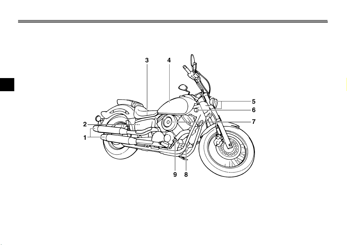
EAU32230
Right view
XVS1100A
1. Muffler
2. Battery (page 7-28)
3. Main fuse (page 7-30)
4. Fuel tank (page 4-10)
5. Front turn signal light (page 7-33)
6. Main switch/steering lock (page 4-2)
7. Air filter element (page 7-13)
8. Rear brake light switch (page 7-22)
9. Brake pedal (page 4-9)
DESCRIPTION
3-4
3
XVS1100AA
1. Muffler
2. Battery (page 7-28)
3. Main fuse (page 7-30)
4. Fuel tank (page 4-10)
5. Front turn signal light (page 7-33)
6. Main switch/steering lock (page 4-2)
7. Air filter element (page 7-13)
8. Rear brake light switch (page 7-22)
9. Brake pedal (page 4-9)
DESCRIPTION
3-5
3
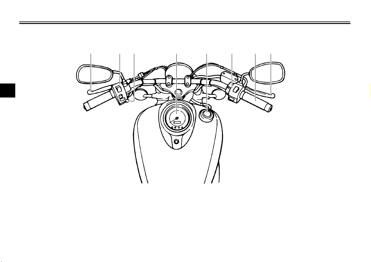
EAU10430
Controls and instruments
1 2 3 4 5 6 7 8
1. Clutch lever (page 4-8)
2. Left handlebar switches (page 4-7)
3. Starter (choke) lever (page 4-12)
4. Speedometer unit (page 4-6)
5. Fuel tank cap (page 4-10)
6. Right handlebar switches (page 4-7)
7. Throttle grip (page 7-15)
8. Brake lever (page 4-9)
INSTRUMENT AND CONTROL FUNCTIONS
4-1
4
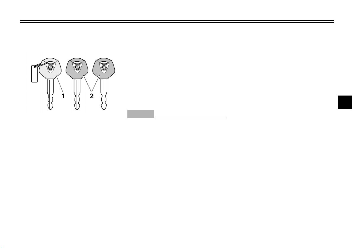
EAU26893
Immobilizer system
(XVS1100AA)
This vehicle is equipped with an immo-
bilizer system to help prevent theft by
re-registering codes in the standard
keys. This system consists of the fol-
lowing:
● a code re-registering key (with a
red bow)
● two standard keys (with a black
bow) that can be re-registered with
new codes
● a transponder (which is installed in
the code re-registering key)
● an immobilizer unit
● the ignitor unit
● an immobilizer system indicator
light (See page 4-5.)
The key with the red bow is used to reg-
ister codes in each standard key. Since
re-registering is a difficult process, take
the vehicle along with all three keys to
a Yamaha dealer to have them re-reg-
istered. Do not use the key with the red
bow for driving. It should only be used
for re-registering the standard keys. Al-
ways use a standard key for driving.
NOTICE
ECA11821
● DO NOT LOSE THE CODE RE-
REGISTERING KEY! CONTACT
YOUR DEALER IMMEDIATELY
IF IT IS LOST! If the code re-reg-
istering key is lost, registering
new codes in the standard keys
is impossible. The standard
keys can still be used to start
the vehicle, however if code re-
registering is required (i.e., if a
new standard key is made or all
keys are lost) the entire immobi-
lizer system must be replaced.
Therefore, it is highly recom-
mended to use either standard
key and keep the code re-regis-
tering key in a safe place.
● Do not submerse any key in wa-
ter.
● Do not expose any key to exces-
sively high temperatures.
● Do not place any key close to
magnets (this includes, but not
limited to, products such as
speakers, etc.).
● Do not place items that transmit
electrical signals close to any
key.
● Do not place heavy items on any
key.
● Do not grind any key or alter its
shape.
● Do not disassemble the plastic
part of any key.
● Do not put two keys of any im-
mobilizer system on the same
key ring.
● Keep the standard keys as well
as keys of other immobilizer
systems away from this vehi-
cle’s code re-registering key.
1. Code re-registering key (red bow)
2. Standard keys (black bow)
INSTRUMENT AND CONTROL FUNCTIONS
4-2
4
● Keep other immobilizer system
keys away from the main switch
as they may cause signal inter-
ference.
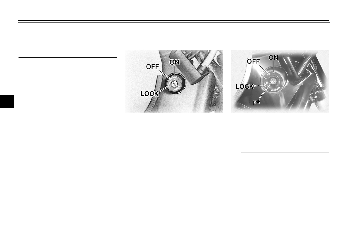
EAU10460
Main switch/steering lock
(XVS1100A)
The main switch/steering lock controls
the ignition and lighting systems, and is
used to lock the steering. The various
positions are described below.
EAU10472
Main switch/steering lock
(XVS1100AA)
The main switch/steering lock controls
the ignition and lighting systems, and is
used to lock the steering. The various
positions are described below.
TIP
Be sure to use the standard key (black
bow) for regular use of the vehicle. To
minimize the risk of losing the code re-
registering key (red bow), keep it in a
safe place and only use it for code re-
registering.
INSTRUMENT AND CONTROL FUNCTIONS
4-3
4
EAU10480
ON (XVS1100A)
All electrical systems are supplied with
power, and the headlight, meter lighting
and taillight come on, and the engine
can be started. The key cannot be re-
moved.
EAU10570
ON (XVS1100AA)
All electrical circuits are supplied with
power; the meter lighting, taillight and
auxiliary light come on, and the engine
can be started. The key cannot be re-
moved.
TIP
The headlight comes on automatically
when the engine is started and stays on
until the key is turned to “OFF”.
EAU10661
OFF
All electrical systems are off. The key
can be removed.
WARNING
EWA10061
Never turn the key to “OFF” or
“LOCK” while the vehicle is moving.
Otherwise the electrical systems will
be switched off, which may result in
loss of control or an accident.
EAU10683
LOCK
The steering is locked, and all electrical
systems are off. The key can be re-
moved.
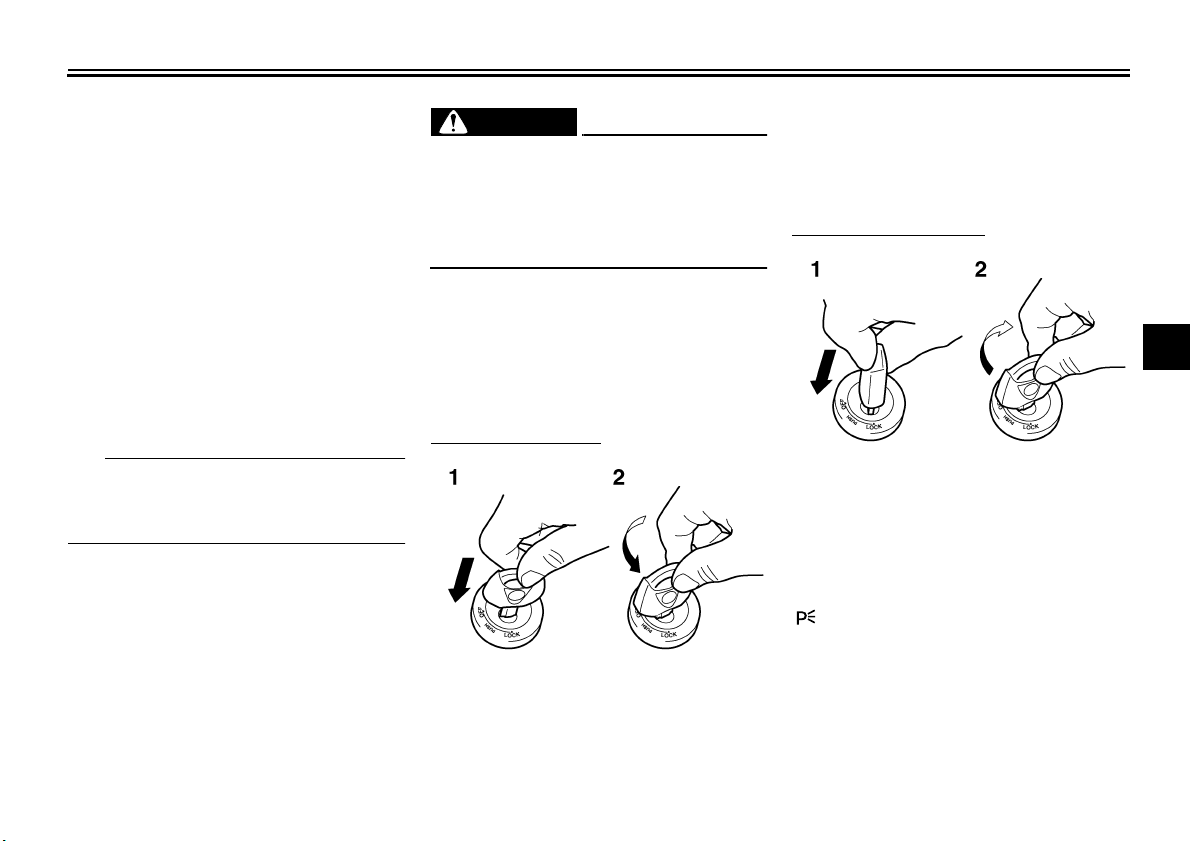
To lock the steering
1. Turn the handlebars all the way to
the left.
2. Push the key in from the “OFF” po-
sition, and then turn it to “LOCK”
while still pushing it.
3. Remove the key.
To unlock the steering
Push the key in, and then turn it to
“OFF” while still pushing it.
EAU33001
(Parking) (XVS1100AA)
The steering is locked, and the taillight
and auxiliary light are on. The hazard
lights and turn signal lights can be
turned on, but all other electrical sys-
tems are off. The key can be removed.
1. Push.
2. Turn.
1. Push.
2. Turn.
INSTRUMENT AND CONTROL FUNCTIONS
4-4
4
The steering must be locked before the
key can be turned to “”.
NOTICE
ECA11020
Do not use the parking position for
an extended length of time, other-
wise the battery may discharge.
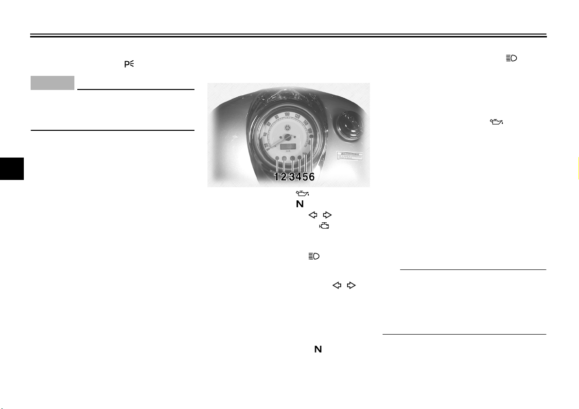
EAU49391
Indicator lights and warning
lights
EAU11020
Turn signal indicator light “”
This indicator light flashes when the
tu rn s ignal switch is push e d t o t he left or
right.
EAU11060
Neutral indicator light “”
This indicator light comes on when the
transmission is in the neutral position.
EAU11080
High beam indicator light “”
This indicator light comes on when the
high beam of the headlight is switched
on.
EAU11123
Oil level warning light “”
This warning light comes on if the en-
gine oil level is low.
The electrical circuit of the warning light
can be checked by turning the key to
“ON”. The warning light should come
on for a few seconds, and then go off.
If the warning light does not come on
initially when the key is turned to “ON”,
or if the warning light remains on, have
a Yamaha dealer check the electrical
circuit.
TIP
Even if the oil level is sufficient, the
warning light may flicker when riding on
a slope or during sudden acceleration
or deceleration, but this is not a mal-
function.
1. Oil level warning light “”
2. Neutral indicator light “”
3. Turn signal indicator light “”
4. Engine trouble warning light “”
5. Immobilizer system indicator light
(XVS1100AA)
6. High beam indicator light “”
INSTRUMENT AND CONTROL FUNCTIONS
4-5
4
EAU11505
Engine trouble warning light “”
This warning light comes on or flashes
if a problem is detected in the electrical
circuit monitoring the engine. If this oc-
curs, have a Yamaha dealer check the
self-diagnosis system. (See page 4-6
for an explanation of the self-diagnosis
device.)
The electrical circuit of the warning light
can be checked by turning the key to
“ON”. The warning light should come
on for a few seconds, and then go off.
If the warning light does not come on
initially when the key is turned to “ON”,
or if the warning light remains on, have
a Yamaha dealer check the electrical
circuit.
EAU38914
Immobilizer system indicator light
(XVS1100AA)
The electrical circuit of the indicator
light can be checked by turning the key
to “ON”. The indicator light should
come on for a few seconds, and then
go off.
If the indicator light does not come on
initially when the key is turned to “ON”,
or if the indicator light remains on, have
a Yamaha dealer check the electrical
circuit.
When the key is turned to “OFF” and 30
seconds have passed, the indicator
light will start flashing indicating the im-
mobilizer system is enabled. After 24
hours have passed, the indicator light
will stop flashing, however the immobi-
lizer system is still enabled.
TIP
The self-diagnosis device also detects
problems in the immobilizer system cir-
cuits. If the immobilizer system is not
working correctly, the indicator light will
start flashing a pattern when the key is
turned to “ON”. When this occurs, have
a Yamaha dealer check the self-diag-
nosis system. However, if the indicator
light slowly flashes five times, and then
quickly flashes two times repeatedly,
this error could be caused by signal in-
terference. If this occurs, try the follow-
ing.
1. Use the code re-registering key to
start the engine.
TIP
Make sure there are no other immobi-
lizer keys close to the main switch, and
do not keep more than one immobilizer
key on the same key ring! Immobilizer
system keys may cause signal interfer-
ence, which may prevent the engine
from starting.
2. If the engine starts, turn it off, and
try starting the engine with the
standard keys.
3. If one or both of the standard keys
do not start the engine, take the
vehicle, the code re-registering
key and both standard keys to a
Yamaha dealer and have the stan-
dard keys re-registered.
INSTRUMENT AND CONTROL FUNCTIONS
4-6
4
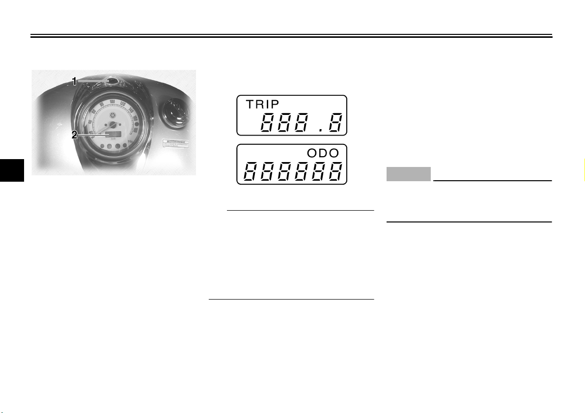
EAU11731
Speedometer unit
The speedometer unit is equipped with
a digital odometer and a tripmeter. The
speedometer shows riding speed. The
odometer shows the total distance trav-
eled. The tripmeter shows the distance
traveled since it was last set to zero.
Pushing the “TRIP” button switches the
display between the odometer mode
“ODO” and the tripmeter mode “TRIP”.
To reset the tripmeter, select it by push-
ing the “TRIP” button, and then push
the “TRIP” button again and hold it
down for at least one second. The trip-
meter can be used to estimate the dis-
tance that can be traveled with a full
tank of fuel. This information will enable
you to plan future fuel stops.
TIP
This model is not equipped with a ta-
chometer; however, it has a built-in
speed limiter, which prevents the en-
gine speed from exceeding approxi-
mately 6800 r/min and the vehicle
speed from exceeding approximately
175 km/h (110 mi/h).
EAU12092
Self-diagnosis device
This model is equipped with a self-diag-
nosis device for various electrical cir-
cuits.
If a problem is detected in any of those
circuits, the engine trouble warning light
will come on or flash. If this occurs,
have a Yamaha dealer check the vehi-
cle.
NOTICE
ECA11170
To prevent engine damage, be sure
to consult a Yamaha dealer as soon
as possible if this occurs.
1. “TRIP” button
2. Odometer/tripmeter
INSTRUMENT AND CONTROL FUNCTIONS
4-7
4
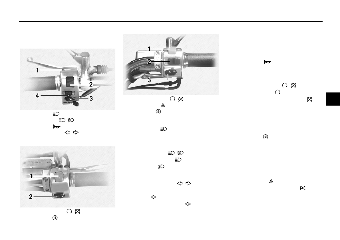
EAU12348
Handlebar switches
Left
Right (XVS1100A)
Right (XVS1100AA)
EAU12350
Pass switch “”
Press this switch to flash the headlight.
EAU12400
Dimmer switch “ / ”
Set this switch to “” for the high
beam and to “” for the low beam.
EAU12460
Turn signal switch “ / ”
To signal a right-hand turn, push this
switch to “”. To signal a left-hand
turn, push this switch to “”. When re-
leased, the switch returns to the center
position. To cancel the turn signal
lights, push the switch in after it has re-
turned to the center position.
EAU12500
Horn switch “”
Press this switch to sound the horn.
EAU12660
Engine stop switch “ / ”
Set this switch to “” before starting
the engine. Set this switch to “” to
stop the engine in case of an emergen-
cy, such as when the vehicle overturns
or when the throttle cable is stuck.
EAU12711
Start switch “”
Push this switch to crank the engine
with the starter. See page 6-1 for start-
ing instructions prior to starting the en-
gine.
EAU12733
Hazard switch “” (XVS1100AA)
With the key in the “ON” or “” posi-
tion, use this switch to turn on the haz-
ard lights (simultaneous flashing of all
turn signal lights).
1. Pass switch “”
2. Dimmer switch “ / ”
3. Horn switch “”
4. Turn signal switch “ / ”
1. Engine stop switch “ / ”
2. Start switch “”
1. Engine stop switch “ / ”
2. Hazard switch “”
3. Start switch “”
INSTRUMENT AND CONTROL FUNCTIONS
4-8
4
The hazard lights are used in case of
an emergency or to warn other drivers
when your vehicle is stopped where it
might be a traffic hazard.
NOTICE
ECA10061
Do not use the hazard lights for an
extended length of time with the en-
gine not running, otherwise the bat-
tery may discharge.
EAU12820
Clutch lever
The clutch lever is located at the left
handlebar grip. To disengage the
clutch, pull the lever toward the handle-
bar grip. To engage the clutch, release
the lever. The lever should be pulled
rapidly and released slowly for smooth
clutch operation.
The clutch lever is equipped with a
clutch switch, which is part of the igni-
tion circuit cut-off system. (See page
4-20.)
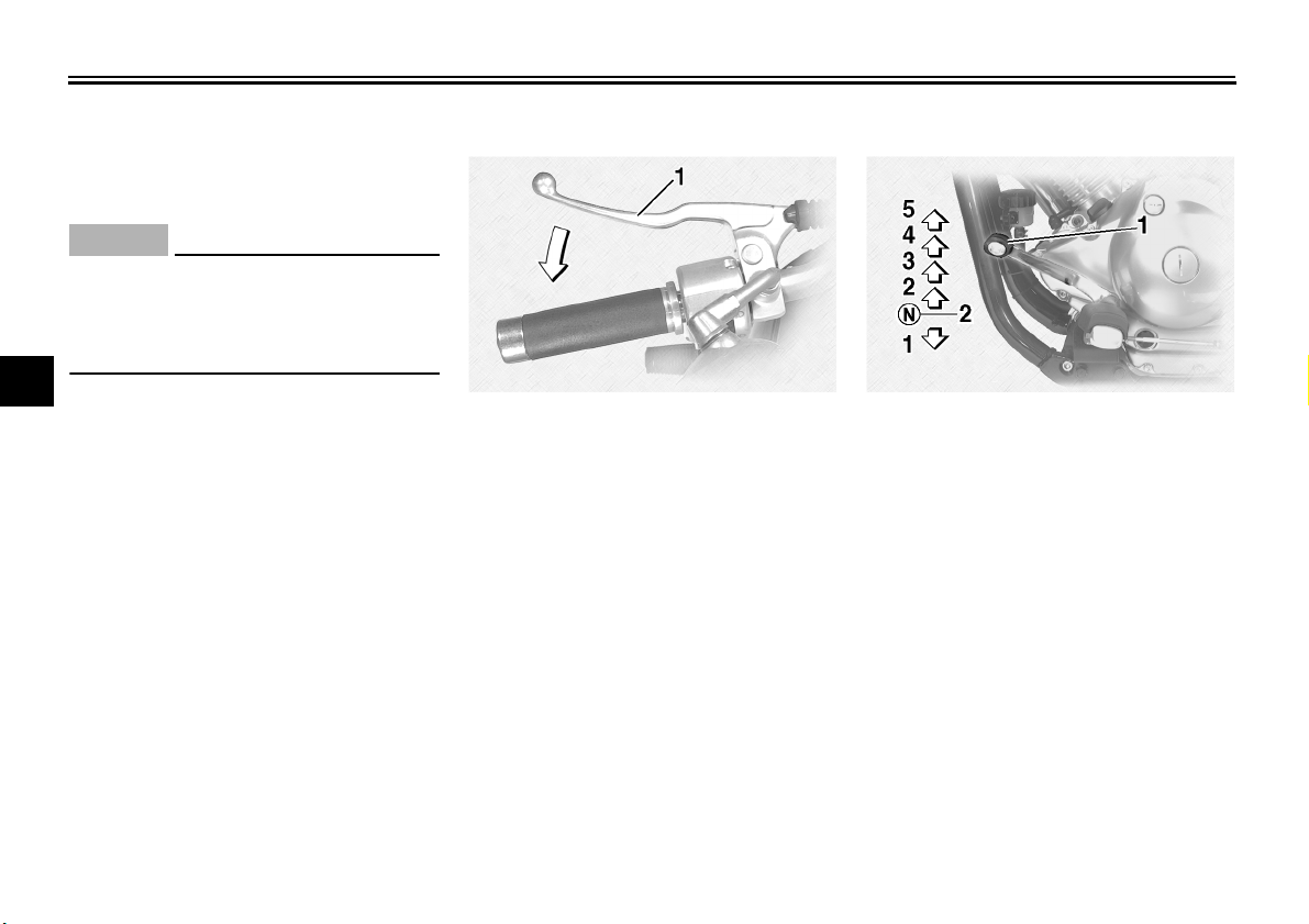
EAU12871
Shift pedal (XVS1100A)
The shift pedal is located on the left
side of the motorcycle and is used in
combination with the clutch lever when
shifting the gears of the 5-speed con-
stant-mesh transmission equipped on
this motorcycle.
1. Clutch lever 1. Shift pedal
2. Neutral position
INSTRUMENT AND CONTROL FUNCTIONS
4-9
4
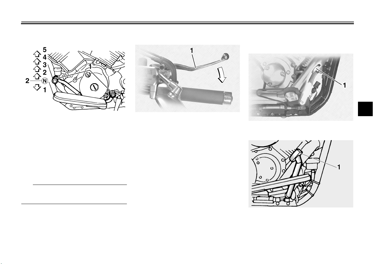
EAU12881
Shift pedal (XVS1100AA)
The shift pedal is located on the left
side of the motorcycle and is used in
combination with the clutch lever when
shifting the gears of the 5-speed con-
stant-mesh transmission equipped on
this motorcycle.
TIP
Use your toes or heel to shift up and
your toes to shift down.
EAU12890
Brake lever
The brake lever is located at the right
handlebar grip. To apply the front
brake, pull the lever toward the handle-
bar grip.
EAU12941
Brake pedal
XVS1100A
XVS1100AA
The brake pedal is on the right side of
the motorcycle. To apply the rear
brake, press down on the brake pedal.
1. Shift pedal
2. Neutral position
1. Brake lever
1. Brake pedal
1. Brake pedal
INSTRUMENT AND CONTROL FUNCTIONS
4-10
4
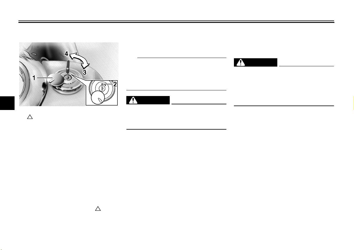
EAU13121
Fuel tank cap
To remove the fuel tank cap
Slide the lock cover open, insert the key
into the lock, and then turn it 1/4 turn
clockwise. The lock will be released
and the fuel tank cap can be removed.
To install the fuel tank cap
1. Insert the fuel tank cap into the
tank opening with the key inserted
in the lock and with the “” mark
facing forward.
2. Turn the key counterclockwise to
the original position, remove it, and
then close the lock cover.
TIP
The fuel tank cap cannot be installed
unless the key is in the lock. In addition,
the key cannot be removed if the cap is
not properly installed and locked.
WARNING
EWA10131
Make sure that the fuel tank cap is
properly installed before riding.
Leaking fuel is a fire hazard.
EAU13212
Fuel
Make sure there is sufficient gasoline in
the tank.
WARNING
EWA10881
Gasoline and gasoline vapors are
extremely flammable. To avoid fires
and explosions and to reduce the
risk of injury when refueling, follow
these instructions.
1. Before refueling, turn off the en-
gine and be sure that no one is sit-
ting on the vehicle. Never refuel
while smoking, or while in the vi-
cinity of sparks, open flames, or
other sources of ignition such as
the pilot lights of water heaters and
clothes dryers.
2. Do not overfill the fuel tank. Stop
filling when the fuel reaches the
bottom of the filler tube. Because
fuel expands when it heats up,
heat from the engine or the sun
can cause fuel to spill out of the
fuel tank.
1. Fuel tank cap lock cover
2. “” mark
3. Unlock.
4. Lock.
 Loading...