


 Loading...
EB000000
XVS1100 (L)
SERVICE MANUAL1998 by Yamaha Motor Co.,Ltd.
First edition, October 1998
All rights reserved. Any reproduction or unauthorized use without the written permission of Yamaha Motor Co., Ltd. is expressly prohibited.

EB001000
NOTICE
This manual was produced by the Yamaha Motor Company primarily for use by Yamaha dealers and their qualified mechanics. It is not possible to include all the knowledge of a mechanic in one manual, so it is assumed that anyone who uses this book to perform maintenance and repairs on Yamaha motorcycles has a basic understanding of the mechanical ideas and the procedures of motorcycle repair. Repairs attempted by anyone without this knowledge are likely to render the motorcycle unsafe and unfit for use.
Yamaha Motor Company, Ltd.is continually striving to improve all its models. Modifications and significant changes in specifications or procedures will be forwarded to all authorized Yamaha dealers and will appear in future editions of this manual where applicable.
NOTE:
Designs and specifications are subject to change without notice.
IMPORTANT INFORMATION
Particularly important information is distinguished in this manual by the following notations.
|
The Safety Alert Symbol means ATTENTION! BECOME ALERT! YOUR |
|||
|
SAFETY IS INVOLVED! |
|||
|
Failure to follow WARNING instructions could result in severe injury or death to |
|||
|
|
|
|
|
|
the motorcycle operator, a bystander or a person inspecting or repairing the |
|||
|
motorcycle. |
|||
|
A CAUTION indicates special precautions that must be taken to avoid damage |
|||
CAUTION: |
||||
|
to the motorcycle. |
|||
NOTE: |
||||
A NOTE provides key information to make procedures easier or clearer. |
||||

EB002000
HOW TO USE THIS MANUAL
MANUAL ORGANIZATION
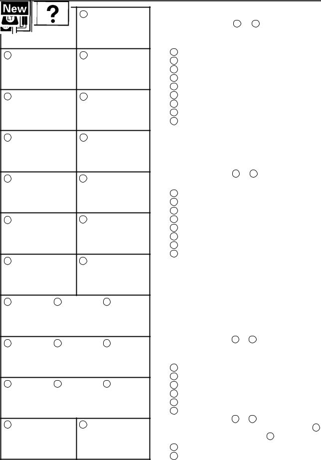
This manual consists of chapters for the main categories of subjects. (See ªIllustrated symbolsº)
1st title 1 : This is the title of the chapter with its symbol in the upper right corner of each page.
2nd title 2 : This title indicates the section of the chapter and only appears on the first page of each section. It is located in the upper right corner of the page.
3rd title 3 : This title indicates a sub-section that is followed by step-by-step procedures accompanied by corresponding illustrations.
EXPLODED DIAGRAMS
To help identify parts and clarify procedure steps, there are exploded diagrams at the start of each removal and disassembly section.
1.An easy-to-see exploded diagram 4 is provided for removal and disassembly jobs.
2.Numbers 5 are given in the order of the jobs in the exploded diagram. A number that is enclosed by a circle indicates a disassembly step.
3.An explanation of jobs and notes is presented in an easy-to-read way by the use of symbol marks 6 . The meanings of the symbol marks are given on the next page.
4.A job instruction chart 7 accompanies the exploded diagram, providing the order of jobs, names of parts, notes in jobs, etc.
5.For jobs requiring more information, the step-by-step format supplements 8 are given in addition to the exploded diagram and the job instruction chart.
2 1 6
3
8
5
4
7
1 |
2 |
3 |
4 |
5 |
6 |
7 |
8 |
9 |
10 |
11 |
12 |
13 |
14 |
15 |
16 |
17 |
18 |
19 |
20 |
21 |
22 |
23 |
24 |
25 |
EB003000
ILLUSTRATED SYMBOLS
Illustrated symbols 1 to 9 are printed on the top right of each page and indicate the subject of each chapter.
1General information
2Specifications
3Periodic inspections and adjustments
4Engine
5Cooling system
6Carburetion
7Chassis
8Electrical
9Troubleshooting
Illustrated symbols 10 to 17 are used to identify the specifications appearing in the text.
10Can be serviced with engine mounted
11Filling fluid
12Lubricant
13Special tool
14Torque
15Wear limit, clearance
16Engine speed
17Ω, V, A
Illustrated symbols 18 to 23 in the exploded diagrams indicate the types of lubricants and lubrication points.
18Apply engine oil
19Apply gear oil
20Apply molybdenum disulfide oil
21Apply wheel bearing grease
22Apply lightweight lithium-soap base grease
23Apply molybdenum disulfide grease
Illustrated symbols 24 to 25 in the exploded diagrams indicate where to apply locking agent 24 and when to install new parts 25 .
24Apply locking agent (LOCTITE )
25Replace
E004000

CHAPTER TITLES
GENERAL INFORMATION |
|
|
|
GEN |
1 |
||
|
INFO |
||
|
|
|
|
SPECIFICATIONS |
|
|
|
SPEC |
2 |
||
|
|||
|
|
|
|
PERIODIC INSPECTION AND |
|
|
|
INSP |
3 |
||
ADJUSTMENTS |
|||
ADJ |
|||
|
|
|
|
ENGINE OVERHAUL |
|
|
|
ENG |
4 |
||
|
|||
|
|
|
|
CARBURETION |
|
|
|
CARB |
5 |
||
|
|||
|
|
|
|
CHASSIS |
|
|
|
CHAS |
6 |
||
|
|||
|
|
|
|
ELECTRICAL |
|
|
|
ELEC |
7 |
||
|
|||
|
|
|
|
TROUBLESHOOTING |
|
|
|
TRBL |
8 |
||
|
SHTG |

INFOGEN 1

GEN
INFO
CHAPTER 1.
GENERAL INFORMATION
MOTORCYCLE IDENTIFICATION . . . . . . . . . . . . . . . . . . . . . . . . . . . . . . . 1-1 VEHICLE IDENTIFICATION NUMBER . . . . . . . . . . . . . . . . . . . . . . . . . 1-1 MODEL LABEL . . . . . . . . . . . . . . . . . . . . . . . . . . . . . . . . . . . . . . . . . . . . . 1-1
IMPORTANT INFORMATION . . . . . . . . . . . . . . . . . . . . . . . . . . . . . . . . . . . . 1-2 PREPARATION FOR REMOVAL PROCEDURES . . . . . . . . . . . . . . . 1-2 REPLACEMENT PARTS . . . . . . . . . . . . . . . . . . . . . . . . . . . . . . . . . . . . . 1-2 GASKETS, OIL SEALS AND O-RINGS . . . . . . . . . . . . . . . . . . . . . . . . 1-2 LOCK WASHERS/PLATES AND COTTER PINS . . . . . . . . . . . . . . . . 1-3 BEARINGS AND OIL SEALS . . . . . . . . . . . . . . . . . . . . . . . . . . . . . . . . . 1-3 CIRCLIPS . . . . . . . . . . . . . . . . . . . . . . . . . . . . . . . . . . . . . . . . . . . . . . . . . . 1-3
CHECKING OF CONNECTIONS . . . . . . . . . . . . . . . . . . . . . . . . . . . . . . . . . 1-4
SPECIAL TOOLS . . . . . . . . . . . . . . . . . . . . . . . . . . . . . . . . . . . . . . . . . . . . . . 1-5
GEN INFO
GEN
MOTORCYCLE IDENTIFICATION INFO
EB100000
GENERAL INFORMATION
MOTORCYCLE IDENTIFICATION
EB100010
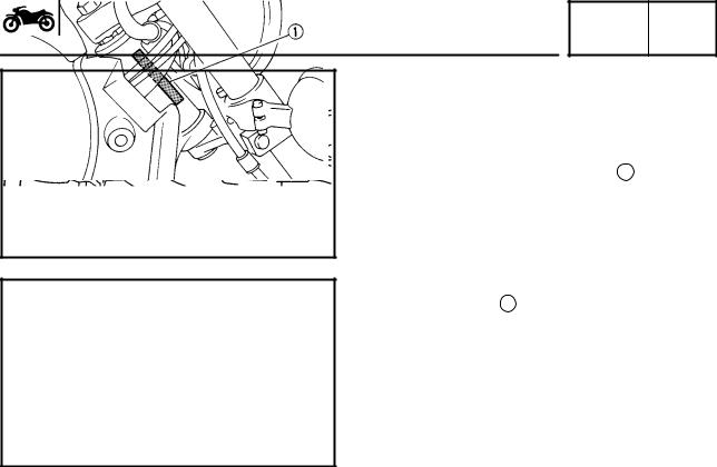
VEHICLE IDENTIFICATION NUMBER
The vehicle identification number 1 is stamped into the right side of the steering head.
MODEL LABEL
The model label 1 is affixed to the frame. This information will be needed to order spare parts.
1-1

GEN
IMPORTANT INFORMATION INFO
EB101000
IMPORTANT INFORMATION
PREPARATION FOR REMOVAL PROCEDURES
1.Remove all dirt, mud, dust and foreign material before removal and disassembly.
2.Use proper tools and cleaning equipment. Refer to the ªSPECIAL TOOLSº section.
3.When disassembling the machine, always keep mated parts together. This includes gears, cylinders, pistons and other parts that have been ªmatedº through normal wear. Mated parts must always be reused or replaced as an assembly.
4.During machine disassembly, clean all parts and place them in trays in the order of disassembly. This will speed up assembly and allow for the correct installation of all parts.
5.Keep all parts away from any source of fire.
EB101010
REPLACEMENT PARTS
1.Use only genuine Yamaha parts for all replacements. Use oil and grease recommended by Yamaha for all lubrication jobs. Other brands may be similar in function and appearance, but inferior in quality.
EB101020
GASKETS, OIL SEALS AND O-RINGS
1.Replace all gaskets, seals and O-rings when overhauling the engine. All gasket surfaces, oil seal lips and O-rings must be cleaned.
2.Properly oil all mating parts and bearings during reassembly. Apply grease to the oil seal lips.
1-2
GEN
IMPORTANT INFORMATION INFO
EB101030
LOCK WASHERS/PLATES AND COTTER PINS
1. Replace all lock washers/plates 1 and cotter pins after removal. Bend lock tabs along the bolt or nut flats after the bolt or nut has been tightened to specification.
EB101040
BEARINGS AND OIL SEALS
1. Install bearings and oil seals so that the manufacturer's marks or numbers are visible. When installing oil seals, apply a light coating of lightweight lithium base grease to the seal lips. Oil bearings liberally when installing, if appropriate.
1 Oil seal
CAUTION:
Do not use compressed air to spin the bearings dry. This will damage the bearing surfaces.
1 Bearing
EB101050
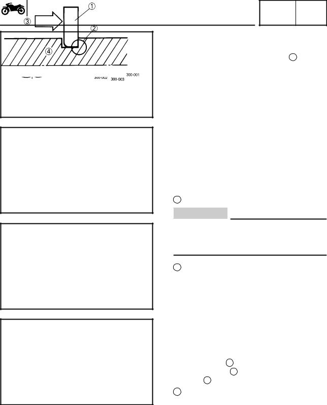
CIRCLIPS
1. Check all circlips carefully before reassembly. Always replace piston pin clips after one use. Replace distorted circlips. When installing a circlip 1 , make sure that the sharpedged corner 2 is positioned opposite the thrust 3 it receives. See sectional view.
4 Shaft
1-3
CHECKING OF CONNECTIONS
EB801000
GEN INFO
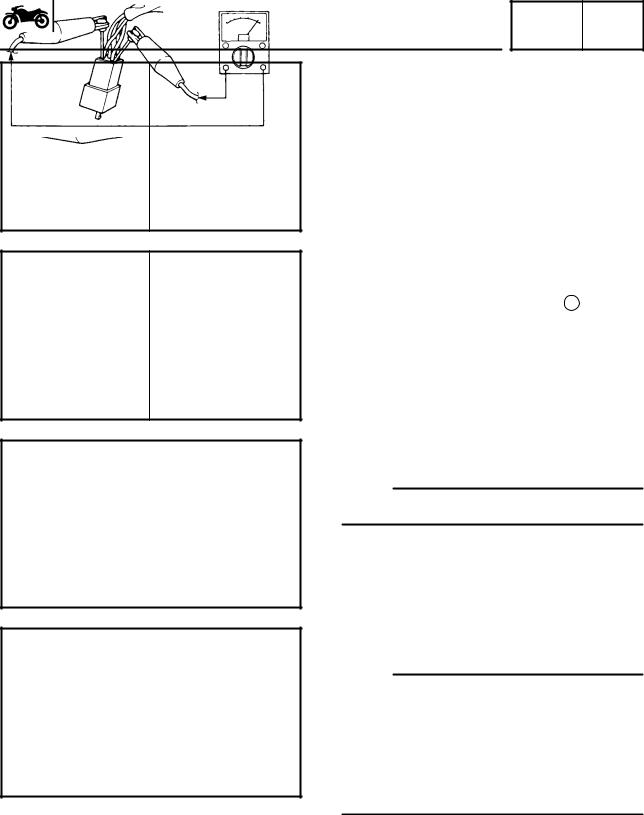
CHECKING OF CONNECTIONS
Check the connectors for stains, rust, moisture, etc.
1.Disconnect:
Connector
2.Check:
Connector
Moisture Dry each terminal with an air blower.
Stains/rust Connect and disconnect the terminals several times.
3.Check:
Connector leads
Looseness Bend up the pin 1 and connect the terminals.
4.Connect:
Connector terminals
NOTE:
The two terminals ªclickº together.
5.Check:
Continuity (using a pocket tester)
NOTE:
If there is no continuity, clean the terminals.
When checking the wire harness be sure to perform steps 1 to 3.
As a quick remedy, use a contact revitalizer available at most part stores.
Check the connector with a pocket tester as shown.
1-4

GEN
SPECIAL TOOLS INFO
EB102001
SPECIAL TOOLS
The following special tools are necessary for complete and accurate tune-up and assembly. Use only the appropriate special tools; this will help prevent damage caused by the use of inappropriate tools or improvised techniques. Special tools may differ by shape and part number from country to country. In such a case, two types are provided.
When placing an order, refer to the list provided below to avoid any mistakes.
Tool No. |
Tool name/How to use |
Illustration |
Slide hammer bolt/weight
Weight 90890-01084
Bolt 90890-01085
These tools are used to remove the rocker arm shaft.
Crankcase separating tool
90890-01135
This tool is used to remove the crankshaft.
Coupling gear/Middle shaft tool
90890-01229
This tool is needed when removing or installing the final pinion shaft nut.
Final gear
Final gear backlash band
backlash band 90890-01230
Middle gear backlash band
This tool is needed when measuring final gear
90890-01231
/middle gear backlash.
Crankshaft installer pot/bolt/adapter/spacer
Installer pot 90890-01274 Bolt 90890-01275 Adaptor 90890-04130 Spacer 90890-04060
These tools are used to install the crankshaft.
Piston pin puller
90890-01304
This tool is used to remove the piston pin.
Fuel level gauge
90890-01312
This gauge is used to measure the fuel level in the float chamber.
1-5
|
SPECIAL TOOLS |
|
|
GEN |
|
|
|
|
|
INFO |
|
||
|
|
|
|
|||
Tool No. |
Tool name/How to use |
|
Illustration |
|||
|
|
|
|
|
|
|
T-handle |
T-handle/damper rod holder |
|
|
|
|
|
|
|
|
|
|
|
|
90890-01326 |
|
|
|
|
|
|
Holder |
These tools are needed to loosen and tighten |
|
|
|
|
|
90890-01460 |
|
|
|
|
|
|
the damper rod holding bolt. |
|
|
|
|
|
|
|
|
|
|
|
|
|
|
|
|
|
|
|
|
Puller |
Flywheel puller/adapter |
|
|
|
|
|
|
|
|
|
|
|
|
90890-01362 |
|
|
|
|
|
|
Adapter |
|
|
|
|
|
|
90890-04131 |
These tools are needed to remove the rotor. |
|
|
|
|
|
|
|
|
|
|
|
|
|
|
|
|
|
|
|
Weight |
Fork seal driver weight/adapter |
|
|
|
|
|
|
|
|
|
|
|
|
90890-01367 |
|
|
|
|
|
|
Adapter |
These tools are needed when installing the |
|
|
|
|
|
90890-01381 |
|
|
|
|
|
|
slide metal, oil seal and dust seal into the fork. |
|
|
|
|
|
|
|
|
|
|
|
|
|
|
|
|
|
|
|
|
Ring nut wrench |
Ring nut wrench/ehaust and steering nut |
|
|
|
|
|
90890-01403 |
wrench |
|
|
|
|
|
|
|
|
|
|
|
|
Exhaust nut |
|
|
|
|
|
|
wrench |
This tool is needed to loosen and tighten the |
|
|
|
|
|
90890-01268 |
|
|
|
|
|
|
steering stem ring nut. |
|
|
|
|
|
|
|
|
|
|
|
|
|
|
|
|
|
|
|
|
|
Sheave holder |
|
|
|
|
|
90890-01701 |
|
|
|
|
|
|
|
This tool is needed to hold the rotor when re- |
|
|
|
|
|
|
moving or installing the rotor bolt. |
|
|
|
|
|
|
|
|
|
|
|
|
|
Compression gauge set |
|
|
|
|
|
90890-03081 |
|
|
|
|
|
|
|
These tools are needed to measure engine |
|
|
|
|
|
|
compression. |
|
|
|
|
|
|
|
|
|
|
|
|
|
Vacuum gauge |
|
|
|
|
|
90890-03094 |
|
|
|
|
|
|
|
This gauge is needed for carburetor synchro- |
|
|
|
|
|
|
nization. |
|
|
|
|
|
|
|
|
|
|
|
|
|
Pocket tester |
|
|
|
|
|
90890-03112 |
|
|
|
|
|
|
|
This instrument is needed for checking the |
|
|
|
|
|
|
electrical system. |
|
|
|
|
|
|
|
|
|
|
|
|
|
Engine tachometer |
|
|
|
|
|
90890-03113 |
|
|
|
|
|
|
|
This tool is needed for observing engine r/min. |
|
|
|
|
|
|
|
|
|
|
|
|
1-6

|
SPECIAL TOOLS |
|
|
GEN |
|
|
|
|
|
INFO |
|
||
|
|
|
|
|||
Tool No. |
Tool name/How to use |
|
Illustration |
|||
|
|
|
|
|
|
|
|
Timing light |
|
|
|
|
|
90890-03141 |
|
|
|
|
|
|
|
This tool is necessary for checking ignition |
|
|
|
|
|
|
timing. |
|
|
|
|
|
|
|
|
|
|
|
|
|
Valve guide remover & installer |
|
|
|
|
|
90890-04014 |
|
|
|
|
|
|
|
This tool is needed to remove and install the |
|
|
|
|
|
|
valve guide. |
|
|
|
|
|
|
|
|
|
|
|
|
|
Valve spring compressor |
|
|
|
|
|
90890-04019 |
|
|
|
|
|
|
|
This tool is needed to remove and install the |
|
|
|
|
|
|
valve assemblies. |
|
|
|
|
|
|
|
|
|
|
|
|
Adapter |
Crankshaft installer bolt adapter/armature |
|
|
|
|
|
90890-01277 |
shock puller/weight |
|
|
|
|
|
Shock puller |
|
|
|
|
|
|
|
|
|
|
|
|
|
90890-01290 |
These tools are needed when removing the |
|
|
|
|
|
Weight |
|
|
|
|
|
|
final pinion shaft. |
|
|
|
|
|
|
90890-01291 |
|
|
|
|
|
|
|
|
|
|
|
|
|
|
Bearing retainer wrench |
|
|
|
|
|
90890-04137 |
|
|
|
|
|
|
|
This tool is needed when removing or instal- |
|
|
|
|
|
|
ling the middle drive shaft assembly. |
|
|
|
|
|
|
|
|
|
|
|
|
Wrench |
Middle drive shaft nut wrench/Middle drive |
|
|
|
|
|
shaft holder |
|
|
|
|
|
|
90890-04138 |
|
|
|
|
|
|
|
|
|
|
|
|
|
Holder |
These tools are needed when removing or |
|
|
|
|
|
90890-04055 |
|
|
|
|
|
|
installing the middle drive shaft bearing. |
|
|
|
|
|
|
|
|
|
|
|
|
|
|
|
|
|
|
|
|
|
Universal joint holder |
|
|
|
|
|
90890-04062 |
|
|
|
|
|
|
|
This tool is needed when removing or instal- |
|
|
|
|
|
|
ling the driven pinion gear nut. |
|
|
|
|
|
|
|
|
|
|
|
|
|
Bearing retainer wrench |
|
|
|
|
|
90890-04077 |
|
|
|
|
|
|
|
This tool is needed when removing or instal- |
|
|
|
|
|
|
ling the final drive pinion gear assembly. |
|
|
|
|
|
|
|
|
|
|
|
|
|
Clutch holding tool |
|
|
|
|
|
90890-04086 |
|
|
|
|
|
|
|
This tool is needed to hold the clutch when re- |
|
|
|
|
|
|
moving or installing the clutch boss nut. |
|
|
|
|
|
|
|
|
|
|
|
|
1-7

|
SPECIAL TOOLS |
|
|
GEN |
|
|
|
|
|
INFO |
|
||
|
|
|
|
|||
Tool No. |
Tool name/How to use |
|
Illustration |
|||
|
|
|
|
|
|
|
|
Damper spring compressor |
|
|
|
|
|
90890-04090 |
|
|
|
|
|
|
|
This tool is needed when removing or instal- |
|
|
|
|
|
|
ling the damper spring. |
|
|
|
|
|
|
|
|
|
|
|
|
|
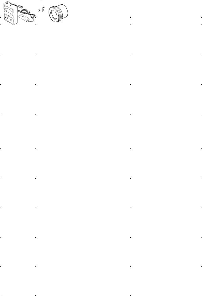
Dynamic spark tester |
|
|
|
|
|
|
Ignition checker |
|
|
|
|
|
90890-06754 |
|
|
|
|
|
|
|
This instrument is necessary for checking the |
|
|
|
|
|
|
ignition system components. |
|
|
|
|
|
|
|
|
|
|
|
|
|
Yamaha bond No.1215 |
|
|
|
|
|
90890-85505 |
|
|
|
|
|
|
|
This sealant (bond) is used on crankcase mat- |
|
|
|
|
|
|
ing surfaces, etc. |
|
|
|
|
|
|
|
|
|
|
|
|
1-8

SPEC 2
E
SPEC 


CHAPTER 2.
SPECIFICATIONS
GENERAL SPECIFICATIONS . . . . . . . . . . . . . . . . . . . . . . . . . . . . . . . . . . . 2-1
MAINTENANCE SPECIFICATIONS . . . . . . . . . . . . . . . . . . . . . . . . . . . . . . 2-4 ENGINE . . . . . . . . . . . . . . . . . . . . . . . . . . . . . . . . . . . . . . . . . . . . . . . . . . . 2-4 CHASSIS . . . . . . . . . . . . . . . . . . . . . . . . . . . . . . . . . . . . . . . . . . . . . . . . . . 2-14 ELECTRICAL . . . . . . . . . . . . . . . . . . . . . . . . . . . . . . . . . . . . . . . . . . . . . . 2-18
GENERAL TORQUE SPECIFICATIONS . . . . . . . . . . . . . . . . . . . . . . . . . . 2-20
CONVERSION TABLE . . . . . . . . . . . . . . . . . . . . . . . . . . . . . . . . . . . . . . . . . . 2-20
LUBRICATION POINTS AND LUBRICANT TYPES . . . . . . . . . . . . . . . . 2-21 ENGINE . . . . . . . . . . . . . . . . . . . . . . . . . . . . . . . . . . . . . . . . . . . . . . . . . . . 2-21 CHASSIS . . . . . . . . . . . . . . . . . . . . . . . . . . . . . . . . . . . . . . . . . . . . . . . . . . 2-22
LUBRICATION DIAGRAMS . . . . . . . . . . . . . . . . . . . . . . . . . . . . . . . . . . . . . 2-23
CABLE ROUTING . . . . . . . . . . . . . . . . . . . . . . . . . . . . . . . . . . . . . . . . . . . . . 2-26

E
SPEC 


|
|
GENERAL SPECIFICATIONS |
|
SPEC |
|
||
|
|
|
|
|
|
|
|
GENERAL SPECIFICATIONS |
SPECIFICATIONS |
|
|
||||
|
|
|
|
|
|
||
|
|
|
|
|
|
||
|
Item |
|
Standard |
|
|
||
|
|
|
|
|
|
||
Model code: |
|
|
XVS1100: 5EL1 (For Europe) |
|
|
||
|
|
|
5EL2 (For D, A, FIN) |
||||
|
|
|
5EL3 (For Australia) |
||||
|
|
|
|
|
|
|
|
Dimensions: |
|
|
|
|
|
|
|
Overall length |
|
|
2,405 mm |
|
|
||
Overall width |
|
|
895 mm |
|
|
||
Overall height |
|
|
1,095 mm |
|
|
||
Seat height |
|
|
690 mm |
|
|
||
Wheelbase |
|
|
1,640 mm |
|
|
||
Minimum ground clearance |
|
145 mm |
|
|
|||
Minimum turning radius |
|
3,200 mm |
|
|
|||
|
|
|
|
|
|
|
|
Basic weight: |
|
|
|
|
|
|
|
With oil and a full fuel tank |
|
274 kg (5EL2 : 275kg) |
|
|
|||
|
|
|
|
|
|
|
|
Engine: |
|
|
|
|
|
|
|
Engine type |
|
|
Air cooled 4-stroke, SOHC |
|
|
||
Cylinder arrangement |
|
V-type 2-cylinder |
|
|
|||
Displacement |
|
|
1.063 L |
|
|
||
Bore stroke |
|
|
95 75mm |
|
|
||
Compression ratio |
|
8.3 : 1 |
|
|
|
|
|
Compression pressure (STD) |
|
1,000 kPa (10 kg/cm2, 10 bar) at 400 r/min |
|||||
Starting system |
|
|
Electric starter |
|
|
||
|
|
|
|
|
|||
Lubrication system: |
|
Wet sump |
|
|
|||
|
|
|
|
|
|
|
|
Oil type or grade: |
|
|
|
|
|
|
|
Engine oil |
Temp. |
C |
API standard: |
|
|
||
|
|
|
ªSEº or higher grade |
|
|
||
|
|
|
ACEA standard: |
|
|
||
|
|
|
G4 or G5 |
|
|
||
Final gear oil: |
SAE80API ªGL-4º Hypoid Gear Oil |
Oil quantity: |
|
Engine oil |
|
Periodic oil change |
3.0 L |
With oil filter replacement |
3.1 L |
Total amount |
3.6 L |
Final gear case oil |
|
Total amount |
0.2 L |
|
|
Air filter: |
Dry type element |
|
|
Fuel: |
|
Type |
Regular unleaded gasoline |
Fuel tank capacity |
17 L |
Fuel reserve amount |
4.5 L |
2-1

|
GENERAL SPECIFICATIONS |
SPEC |
|
||
|
|
|
|
|
|
|
|
|
|
|
|
|
Item |
Standard |
|
|
|
|
|
|
|
|
|
Carburetor: |
|
|
|
|
|
Type/quantity |
|
BSR37/2 |
|
|
|
Manufacturer |
|
MIKUNI |
|
|
|
|
|
|
|
|
|
Spark plug: |
|
|
|
|
|
Type |
|
BPR7ES/W22EPR±U |
|
|
|
Manufacturer |
|
NGK/DENSO |
|
|
|
Spark plug gap |
0.7 X 0.8 mm |
|
|
||
|
|
|
|
|
|
Clutch type: |
|
Wet, multiple-disc |
|
|
|
|
|
|
|
|
|
Transmission: |
|
|
|
|
|
Primary reduction system |
Spur gear |
|
|
||
Primary reduction ratio |
78/47 (1.660) |
|
|
|
|
Secondary reduction system |
Shaft drive |
|
|
||
Secondary reduction ratio |
44/47 19/18 32/11 (2.875) |
||||
Transmission type |
Constant mesh 5-speed |
|
|
||
Operation |
|
Left foot operation |
|
|
|
Gear ratio |
1st |
40/17 (2.353) |
|
|
|
|
2nd |
40/24 (1.667) |
|
|
|
|
3rd |
36/28 (1.286) |
|
|
|
|
4th |
32/31 (1.032) |
|
|
|
|
5th |
29/34 (0.853) |
|
|
|
|
|
|
|
|
|
Chassis: |
|
|
|
|
|
Frame type |
|
Double cradle |
|
|
|
Caster angle |
|
33 |
|
|
|
Trail |
|
136 mm |
|
|
|
|
|
|
|
|
|
Tire: |
|
|
|
|
|
Type |
|
With tube |
|
|
|
Size |
front |
110/90-18 61S |
|
|
|
|
rear |
170/80-15M/C 77S |
|
|
|
Manufacturer |
front |
BRIDGESTONE/DUNLOP |
|
|
|
|
rear |
BRIDGESTONE/DUNLOP |
|
|
|
Type |
front |
EXEDRA L309/K555F |
|
|
|
|
rear |
EXEDRA G546/K555 |
|
|
|
|
|
|
|
||
Maximum load-except motorcycle: |
201 kg (5EL2 : 200kg) |
|
|
||
|
|
|
|
|
|
Tire pressure (cold tire): |
|
|
|
|
|
0 X 90 kg (0 |
X 198 lb) load * |
|
|
|
|
|
front |
200 kPa (2.00 kg/cm2) |
|
|
|
|
rear |
225 kPa (2.25 kg/cm2) |
|
|
|
90 kg (198 lb) X Maximum load * |
|
|
|
|
|
|
front |
225 kPa (2.25 kg/cm2) |
|
|
|
|
rear |
250 kPa (2.50 kg/cm2) |
|
|
|
|
|
* Load is the total weight of the cargo, rider, |
|||
|
|
passenger and accessories. |
|
|
|
|
|
|
|
|
|
Brake: |
|
|
|
|
|
Front brake |
type |
Dual disc brake |
|
|
|
|
operation |
Right hand operation |
|
|
|
Rear brake |
type |
Single disc brake |
|
|
|
|
operation |
Right foot operation |
|
|
|
|
|
|
|
|
|
2-2

|
GENERAL SPECIFICATIONS |
SPEC |
|
|||
|
|
|
|
|
|
|
|
|
|
|
|
|
|
Item |
|
|
Standard |
|
|
|
|
|
|
|
|
|
|
Suspension: |
|
|
|
|
|
|
Front suspension |
|
Telescopic fork |
|
|
||
Rear suspension |
|
Swingarm (link suspension) |
|
|
||
|
|
|
|
|
|
|
Shock absorber: |
|
|
|
|
|
|
Front shock absorber |
|
Coil spring/Oil damper |
|
|
||
Rear shock absorber |
|
Coil spring/Gas-oil damper |
|
|
||
|
|
|
|
|
|
|
Wheel travel: |
|
|
|
|
|
|
Front wheel travel |
|
140 mm |
|
|
||
Rear wheel travel |
|
113 mm |
|
|
||
|
|
|
|
|
|
|
Electrical: |
|
|
|
|
|
|
Ignition system |
|
T.C.I. (digital) |
|
|
||
Generator system |
|
A.C. magneto |
|
|
||
Battery type |
|
GT14B-4 |
|
|
||
Battery capacity |
|
12 |
V 12 AH |
|
|
|
|
|
|
|
|
||
Headlight type: |
|
Quartz bulb (halogen) |
|
|
||
|
|
|
|
|
|
|
Bulb wattage quantity: |
|
|
|
|
|
|
Headlight |
|
12 V 60 W/55 W 1 |
|
|
||
Auxiliary light |
|
12 |
V 4 W 1 |
|
|
|
Tail/brake light |
|
12 |
V 5 W/21 W 1 |
|
|
|
Turn signal |
|
12 |
V 21 W 4 |
|
|
|
Licence light |
|
12 |
V 5 W 1 |
|
|
|
Meter light |
|
14 |
V 1.4 W 2 |
|
|
|
Neutral indicator light |
|
12 |
V 1.7 W 1 |
|
|
|
High beam indicator light |
|
12 |
V 1.7 W 1 |
|
|
|
Turn indicator light |
|
12 |
V 1.7 W 1 |
|
|
|
Oil level caution light |
|
12 |
V 1.7 W 1 |
|
|
|
Engine warning light |
|
12 |
V 1.7 W 1 |
|
|
|
2-3

MAINTENANCE SPECIFICATIONS SPEC
MAINTENANCE SPECIFICATIONS
ENGINE
Item |
Standard |
Limit |
Cylinder head: |
|
|
Warp limit |
SSS |
0.03 mm |
Cylinder: |
|
|
Bore size |
95.00 X 95.01 mm |
95.1 mm |
Measuring point |
40 mm |
SSS |
Camshaft: |
|
|
Drive method |
Chain drive (left & right) |
SSS |
Cam cap inside diameter |
25.000 X 25.021 mm |
SSS |
Camshaft outside diameter |
24.96 X 24.98 mm |
SSS |
Shaft-to-cap clearance |
0.020 X 0.061 mm |
SSS |
Cam dimensions |
|
|
Intake |
ªAº |
39.112 X 39.212 mm |
39.012 mm |
|
ªBº |
#1: 32.093 X 32.193 mm |
#1: 31.993 mm |
|
|
#2: 32.127 X 32.227 mm |
#2: 32.027 mm |
|
ªCº |
7.162 mm |
7.012 mm |
Exhaust |
ªAº |
39.145 X 39.245 mm |
39.045 mm |
|
ªBº |
32.200 X 32.300 mm |
32.100 mm |
|
ªCº |
7.195 mm |
7.045 mm |
Camshaft runout limit |
|
SSS |
0.03 mm |
2-4

|
MAINTENANCE SPECIFICATIONS |
|
SPEC |
|
||
|
|
|
|
|
|
|
|
|
|
|
|
|
|
Item |
|
Standard |
|
|
Limit |
|
|
|
|
|
|
|
|
Timing chain: |
|
|
|
|
|
|
Timing chain type/No. of links |
SILENT CHAIN/98L |
|
|
SSS |
||
Timing chain adjustment method |
Automatic |
|
|
SSS |
||
|
|
|
|
|
|
|
Rocker arm/rocker arm shaft: |
|
|
|
|
|
|
Bearing inside diameter |
|
14.000 mm X 14.018 mm |
|
|
14.036 mm |
|
Shaft outside diameter |
|
13.985 mm X 13.991 mm |
|
|
13.95 mm |
|
Arm-to-shaft clearance |
|
0.009 mm X 0.033 mm |
|
|
0.086 mm |
|
|
|
|
|
|
|
|
Valve, valve seat, valve guide: |
|
|
|
|
|
|
Valve clearance (cold) |
IN |
0.07 X 0.12 mm |
|
|
SSS |
|
|
EX |
0.12 X 0.17 mm |
|
|
SSS |
|
Valve dimensions: |
|
|
|
|
|
|
Head Dia |
Face width |
|
Seat Width |
Margin Thickness |
|
ªAº head diameter |
IN |
|
47.0 X 47.2 mm |
|
SSS |
|
|
||||
|
EX |
|
39.0 X 39.2 mm |
|
SSS |
ªBº face width |
IN |
|
2.1 mm |
|
SSS |
|
EX |
|
2.1 mm |
|
SSS |
ªCº seat width |
IN |
|
1.2 X 1.4 mm |
|
1.8 mm |
|
EX |
|
1.2 X 1.4 mm |
|
1.8 mm |
ªDº margin thickness |
IN |
|
1.1 X 1.5 mm |
|
0.8 mm |
|
EX |
|
1.1 X 1.5 mm |
|
0.8 mm |
Stem outside diameter |
IN |
|
7.975 X 7.990 mm |
|
SSS |
|
EX |
|
7.960 X 7.975 mm |
|
SSS |
Guide inside diameter |
IN |
|
8.000 X 8.012 mm |
|
SSS |
|
EX |
|
8.000 X 8.012 mm |
|
SSS |
Stem-to-guide clearance |
IN |
|
0.010 X 0.037 mm |
|
0.08 mm |
|
EX |
|
0.025 X 0.052 mm |
|
0.10 mm |
2-5

|
MAINTENANCE SPECIFICATIONS |
|
SPEC |
|
|
|
|
|
|
|
|
|
|
|
Item |
Standard |
|
Limit |
|
|
|
|
|
|
Stem runout limit |
SSS |
|
0.03 mm |
|
Valve seat width |
IN |
1.2 X 1.4 mm |
2.0 mm |
|
EX |
1.2 X 1.4 mm |
2.0 mm |
|
|
|
|
Valve spring: |
|
|
|
Free length |
IN |
44.6 mm |
43.5 mm |
|
EX |
44.6 mm |
43.5 mm |
Set length (valve closed) |
IN |
40 mm |
SSS |
|
EX |
40 mm |
SSS |
Compressed pressure |
IN |
160.7 N (16.4 kg) |
SSS |
(installed) |
EX |
160.7 N (16.4 kg) |
SSS |
Tilt limit |
IN |
SSS |
2.5_/1.9mm |
|
EX |
SSS |
2.5_/1.9mm |
Direction of winding |
|
|
|
(top view) |
IN |
Clockwise |
SSS |
|
EX |
Clockwise |
SSS |
|
|
|
|
Piston: |
|
|
|
Piston to cylinder clearance |
|
0.025 X 0.050 mm |
0.15 mm |
Piston size ªDº |
|
94.960 X 94.975 mm |
SSS |
Measuring point ªHº |
5 mm |
SSS |
Piston off-set |
0 mm |
SSS |
2-6

MAINTENANCE SPECIFICATIONS |
|
SPEC |
|
|
|
|
|
|
|
|
|
|
|
|
Item |
Standard |
|
Limit |
|
|
|
|
|
|
Piston pin bore inside diameter |
22.004 X 22.015 mm |
|
SSS |
|
Piston pin outside diameter |
21.991 X 22.000 mm |
|
SSS |
|
|
|
|
|
|
Piston rings: |
|
|
|
|
Top ring: |
|
|
|
|
Type |
Plain |
|
SSS |
|
Dimensions (B T) |
1.5 3.8 mm |
|
SSS |
|
End gap (installed) |
0.3 X 0.5 mm |
|
0.8 mm |
|
Side clearance (installed) |
0.04 X 0.08 mm |
|
0.1 mm |
|
2nd ring: |
|
|
|
|
Type |
Taper |
|
SSS |
|
Dimensions (B T) |
1.2 3.8 mm |
|
SSS |
|
End gap (installed) |
0.30 X 0.45 mm |
|
0.8 mm |
|
Side clearance |
0.03 X 0.07 mm |
|
0.1 mm |
|
Oil ring: |
|
|
|
|
Dimensions (B T) |
2.5 3.4 mm |
SSS |
End gap (installed) |
0.2 X 0.7 mm |
SSS |
|
|
|
Connecting rod: |
|
|
Oil clearance |
0.044 X 0.073 mm |
SSS |
Color code (corresponding size) |
1 Blue 2 Black 3 Brown 4 Green 5 Yellow |
SSS |
|
|
|
Crankshaft: |
|
|
Crank width ªAº |
101.95 X 102.00 mm |
SSS |
Runout limit ªCº |
SSS |
0.02 mm |
Big end side clearance ªDº |
0.320 X 0.474 mm |
SSS |
2-7

|
MAINTENANCE SPECIFICATIONS |
|
SPEC |
|
||||
|
|
|
|
|
|
|
|
|
|
|
|
|
|
|
|||
Item |
|
|
Standard |
|
Limit |
|||
|
|
|
|
|
|
|
|
|
Clutch: |
|
|
|
|
|
|
|
|
Friction plate thickness |
|
2.9 |
X 3.1 mm |
|
2.8 mm |
|||
Quantity |
|
8 |
|
|
|
|
SSS |
|
Clutch plate thickness |
|
2.5 |
X 2.7 mm |
|
0.1 mm |
|||
Quantity |
|
1 |
|
|
|
|
SSS |
|
Clutch plate thickness |
|
1.9 |
X 2.1 mm |
|
0.1 mm |
|||
Quantity |
|
7 |
|
|
|
|
|
|
Clutch spring free length |
|
7.2 mm |
|
6.5 mm |
||||
Quantity |
|
1 |
|
|
|
|
SSS |
|
Clutch housing thrust clearance |
0.05 X 0.40 mm |
|
SSS |
|||||
Clutch housing radial clearance |
0.010 X 0.044 mm |
|
SSS |
|||||
Clutch release method |
|
Inner push, screw push |
|
SSS |
||||
Push rod bending limit |
|
SSS |
|
|
|
|
0.5 mm |
|
|
|
|
|
|
|
|
|
|
Transmission: |
|
|
|
|
|
|
|
|
Main axle deflection limit |
|
SSS |
|
|
|
|
0.08 mm |
|
Drive axle deflection limit |
|
SSS |
|
|
|
|
0.08 mm |
|
|
|
|
|
|
|
|
|
|
Shifter: |
|
|
|
|
|
|
|
|
Shifter type |
|
Guide bar |
|
SSS |
||||
|
|
|
|
|
|
|
|
|
Carburetor: |
|
|
|
|
|
|
|
|
I. D. mark |
|
5EL1 00 |
|
SSS |
||||
Main jet |
(M.J) |
#1: #110, #2: #112.5 |
|
|
|
SSS |
||
Main air jet |
(M.A.J) |
#55 |
|
|
|
|
SSS |
|
Jet needle |
(J.N) |
#1: 5DL39-53-3/5, #2: 5DL40-53-3/5 |
|
SSS |
||||
Needle jet |
(N.J) |
P-0M |
|
SSS |
||||
Pilot air jet |
(P.A.J.1) |
#63.8 |
|
|
|
SSS |
||
|
(P.A.J.2) |
#145 |
|
|
|
SSS |
||
Pilot outlet |
(P.O) |
1.0 |
|
|
|
|
SSS |
|
Pilot jet |
(P.J) |
#17.5 |
|
|
|
SSS |
||
Bypass 1 |
(B.P.1) |
0.8 |
|
|
|
|
SSS |
|
Bypass 2 |
(B.P.2) |
0.8 |
|
|
|
|
SSS |
|
Bypass 3 |
(B.P.3) |
0.8 |
|
|
|
|
SSS |
|
Pilot screw |
(P.S) |
3 |
|
|
|
|
SSS |
|
Valve seat size |
(V.S) |
1.2 |
|
|
|
|
SSS |
|
Starter jet |
(G.S.1) |
#42.5 |
|
|
|
SSS |
||
Starter jet |
(G.S.2) |
0.8 |
|
|
|
|
SSS |
|
Throttle valve size |
(Th.V) |
#125 |
|
|
|
SSS |
||
Fuel level |
(F.L) |
4X5 mm |
|
SSS |
||||
Engine idle speed |
|
950 X 1,050 r/min |
|
SSS |
||||
Intake vacuum |
|
34.7 X 37.3 kPa (260 X 280 mmHg) |
|
SSS |
||||
Engine oil temperature |
|
75 X 85_C |
|
SSS |
||||
Fuel pump: |
|
|
|
|
|
|
|
|
Type |
|
Electrical type |
|
SSS |
||||
Model/manufacturer |
|
UC-Z6M/MITSUBISHI |
|
SSS |
||||
Consumption amperage |
<max> |
0.8 |
A |
|
SSS |
|||
Output pressure |
|
12 kPa (0.12 kg/cm2) |
|
SSS |
||||
2-8
Loading...