


XV16AL/XV16ALC XV16ATL/XV16ATLC
SERVICEMANUAL
LIT-11616-12-56 |
4WM-28197-E0 |

EAS00001
XV16AL/XV16ALC
XV16ATL/XV16ATLC
SERVICE MANUAL
1998 by Yamaha Motor Corporation, U.S.A.
First Edition, October 1998
All rights reserved. Any reproduction or unauthorized use without the written permission of Yamaha Motor Corporation, U.S.A. is expressly prohibited.
Printed in U.S.A.
P/N LIT-11616-12-56
EAS00003
NOTICE
This manual was produced by the Yamaha Motor Company, Ltd. primarily for use by Yamaha dealers and their qualified mechanics. It is not possible to include all the knowledge of a mechanic in one manual. Therefore, anyone who uses this book to perform maintenance and repairs on Yamaha vehicles should have a basic understanding of mechanics and the techniques to repair these types of vehicles. Repair and maintenance work attempted by anyone without this knowledge is likely to render the vehicle unsafe and unfit for use.
This model has been designed and manufactured to perform within certain specifications in regard to performance and emissions. Proper service with the correct tools is necessary to ensure that the vehicle will operate as designed. If there is any question about a service procedure, it is imperative that you contact a Yamaha dealer for any service information changes that apply to this model. This policy is intended to provide the customer with the most satisfaction from his vehicle and to conform with federal environmental quality objectives.
Yamaha Motor Company, Ltd. is continually striving to improve all of its models. Modifications and significant changes in specifications or procedures will be forwarded to all authorized Yamaha dealers and will appear in future editions of this manual where applicable.
This Service Manual contains information regarding periodic maintenance to the emission control system. Please read this material carefully.
NOTE:
Designs and specifications are subject to change without notice.
EAS00004
IMPORTANT MANUAL INFORMATION
Particularly important information is distinguished in this manual by the following.
 WARNING

 CAUTION:

NOTE:
The Safety Alert Symbol means ATTENTION! BECOME ALERT! YOUR SAFETY IS INVOLVED!
Failure to follow WARNING instructions could result in severe injury or death to the motorcycle operator, a bystander or a person checking or repairing the motorcycle.
A CAUTION indicates special precautions that must be taken to avoid damage to the motorcycle.
A NOTE provides key information to make procedures easier or clearer.
EAS00007
HOW TO USE THIS MANUAL
This manual is intended as a handy, easy-to-read reference book for the mechanic. Comprehensive explanations of all installation, removal, disassembly, assembly, repair and check procedures are laid out with the individual steps in sequential order.
1 The manual is divided into chapters. An abbreviation and symbol in the upper right corner of each page indicate the current chapter.
Refer to “SYMBOLS”.
2 Each chapter is divided into sections. The current section title is shown at the top of each page, except in Chapter 3 (“PERIODIC CHECKS AND ADJUSTMENTS”), where the sub section title(s) appears.
3 Sub section titles appear in smaller print than the section title.
4 To help identify parts and clarify procedure steps, there are exploded diagrams at the start of each removal and disassembly section.
5 Numbers are given in the order of the jobs in the exploded diagram. A circled number indicates a disassembly step.
6 Symbols indicate parts to be lubricated or replaced. Refer to “SYMBOLS”.
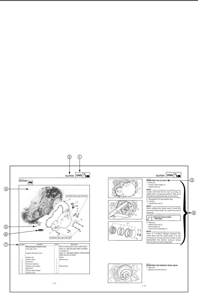
7 A job instruction chart accompanies the exploded diagram, providing the order of jobs, names of parts, notes in jobs, etc.
8 Jobs requiring more information (such as special tools and technical data) are described sequentially.
1 |
|
|
|
2 |
GEN |
|
|
|
SPEC |
INFO |
|
|
|
|
|
|
|
|
|
3 |
|
|
|
4 |
CHK |
|
|
|
CHAS |
ADJ |
|
|
|
|
|
|
|
|
|
5 |
|
|
|
6 |
ENG |
|
|
|
CARB |
7 |
|
|
|
8 |
ELEC |
– |
+ |
|
TRBL |
|
|
|
|
SHTG |
9 |
|
|
|
0 |
A |
|
|
|
B |
C |
|
|
|
D |
|
T |
|
|
|
|
. |
|
|
|
|
R |
|
|
|
|
. |
|
|
|
E |
|
|
|
F |
G |
|
H |
|
I |
E |
|
|
G |
M |
J |
|
K |
|
L |
B |
|
|
LS |
M |
M |
|
|
|
N |
LT |
|
|
|
New |
|
|
|
|
********
SYMBOLS
The following symbols are not relevant to every vehicle.
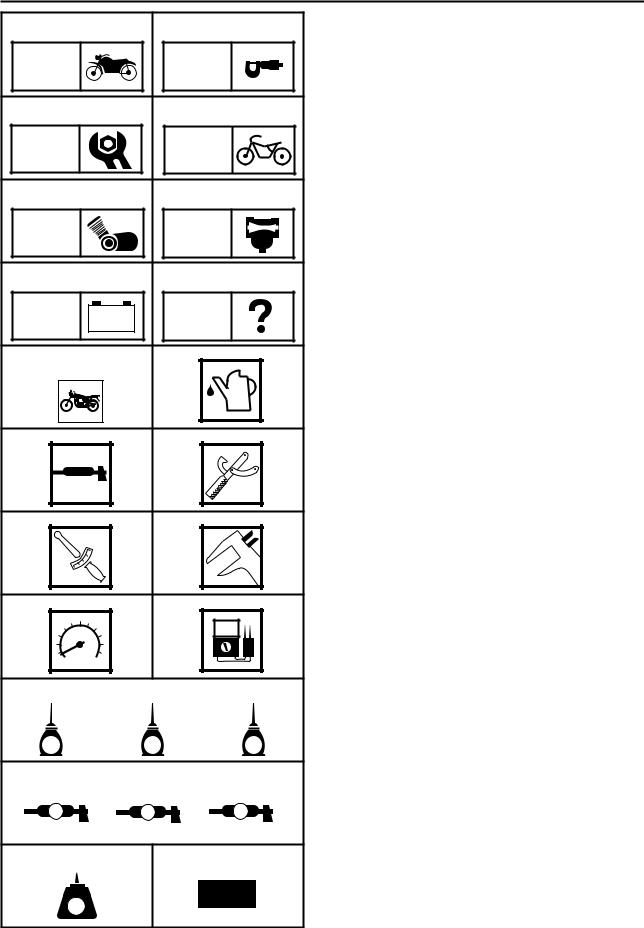
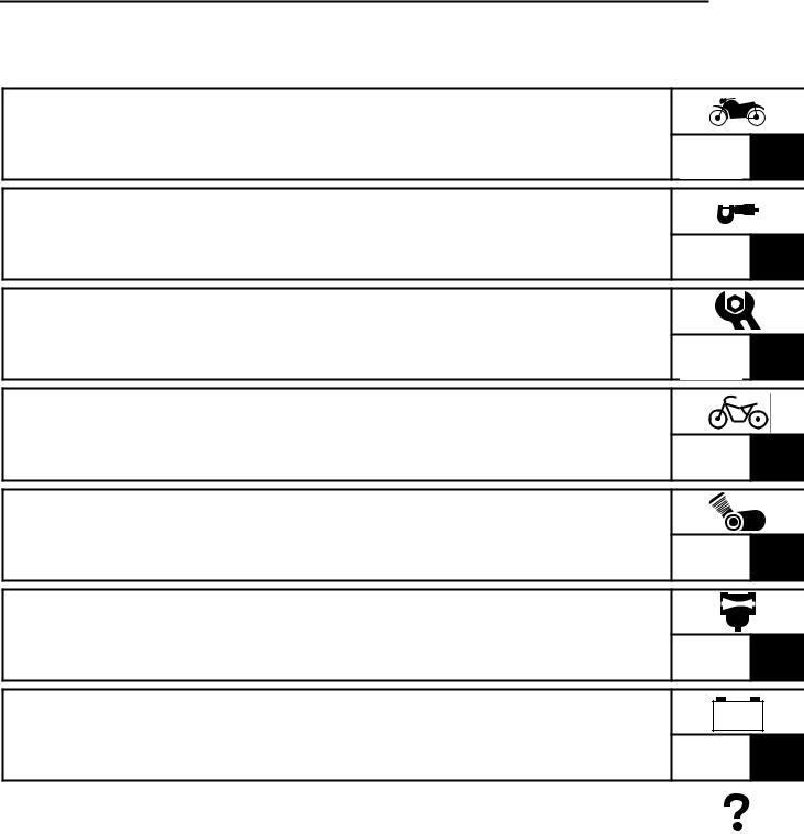
Symbols 1 to 8 indicate the subject of each chapter.
1 General information
2 Specifications
3 Periodic checks and adjustments
4 Chassis
5 Engine
6 Carburetor
7 Electrical system
8 Troubleshooting
Symbols 9 to F indicate the following.
9 Serviceable with engine mounted
0 Filling fluid A Lubricant B Special tool
C Tightening torque
D Wear limit, clearance E Engine speed
F Electrical data
Symbols G to L in the exploded diagrams indicate the types of lubricants and lubrication points.
G Engine oil
H Gear oil
I Molybdenum disulfide oil
J Wheel bearing grease
K Lithium soap base grease
L Molybdenum disulfide grease
Symbols M to N in the exploded diagrams indicate the following.
M Apply locking agent (LOCTITE ).
N Replace the part.
********
TABLE OF CONTENTS
GENERAL INFORMATION |
GEN |
1 |
|
INFO |
|
SPECIFICATIONS |
SPEC |
2 |
|
||
PERIODIC CHECKS AND |
|
3 |
ADJUSTMENTS |
CHK |
|
ADJ |
||
CHASSIS |
CHAS |
4 |
|
||
ENGINE |
ENG |
5 |
|
||
CARBURETION |
CARB |
6 |
|
||
|
– |
+ |
ELECTRICAL SYSTEM |
ELEC |
7 |
|
TROUBLESHOOTING |
|
|
|
|
|
|
TRBL |
|
8 |
||
|
|
SHTG |
|
||

GEN
INFO
CONTENTS
GENERAL INFORMATION
MOTORCYCLE IDENTIFICATION ................................................................ |
1-1 |
|
VEHICLE IDENTIFICATION NUMBER .................................................. |
1-1 |
|
MODEL CODE |
1-1 |
1 |
|
||
FEATURES |
1-2 |
|
|
||
IMPORTANT INFORMATION ...................................................................... |
1-6 |
|
PREPARATION FOR REMOVAL AND DISASSEMBLY ....................... |
1-6 |
|
REPLACEMENT PARTS ........................................................................ |
1-6 |
|
GASKETS, OIL SEALS AND O-RINGS ................................................ |
1-6 |
|
LOCK WASHERS/PLATES AND COTTER PINS .................................. |
1-7 |
|
BEARINGS AND OIL SEALS ................................................................ |
1-7 |
|
CIRCLIPS ............................................................................................... |
1-7 |
|
CHECKING THE CONNECTIONS ................................................................. |
1-8 |
|
SPECIAL TOOLS ........................................................................................... |
1-9 |
|

|
|
|
|
|
|
|
|
|
|
MOTORCYCLE IDENTIFICATION |
|
GEN |
|
|
|
|
|
|
INFO |
|
|
||
|
|
|
|
|
|
|
|
|
|
|
EAS00014 |
||||
|
|
|
GENERAL INFORMATION |
||||
|
|
|
MOTORCYCLE IDENTIFICATION |
||||
|
|
|
EAS00017 |
||||
|
|
|
VEHICLE IDENTIFICATION NUMBER |
||||
|
|
|
The vehicle identification number 1 is |
||||
|
|
|
stamped into the right side of the steering |
||||
1 |
|
|
|||||
|
|
head pipe. |
|||||
|
|
|
|||||
|
|
|
EAS00018 |
||||
|
|
|
|||||
|
|
|
|||||
|
|
|
MODEL CODE |
||||
|
|
|
The model code label 1 is affixed to the |
||||
|
|
|
frame. This information will be needed to |
||||
|
|
|
order spare parts. |
||||
|
|
|
|
|
|
|
|
1 - 1
FEATURES
EAS00019
GEN INFO
FEATURES |
|
|
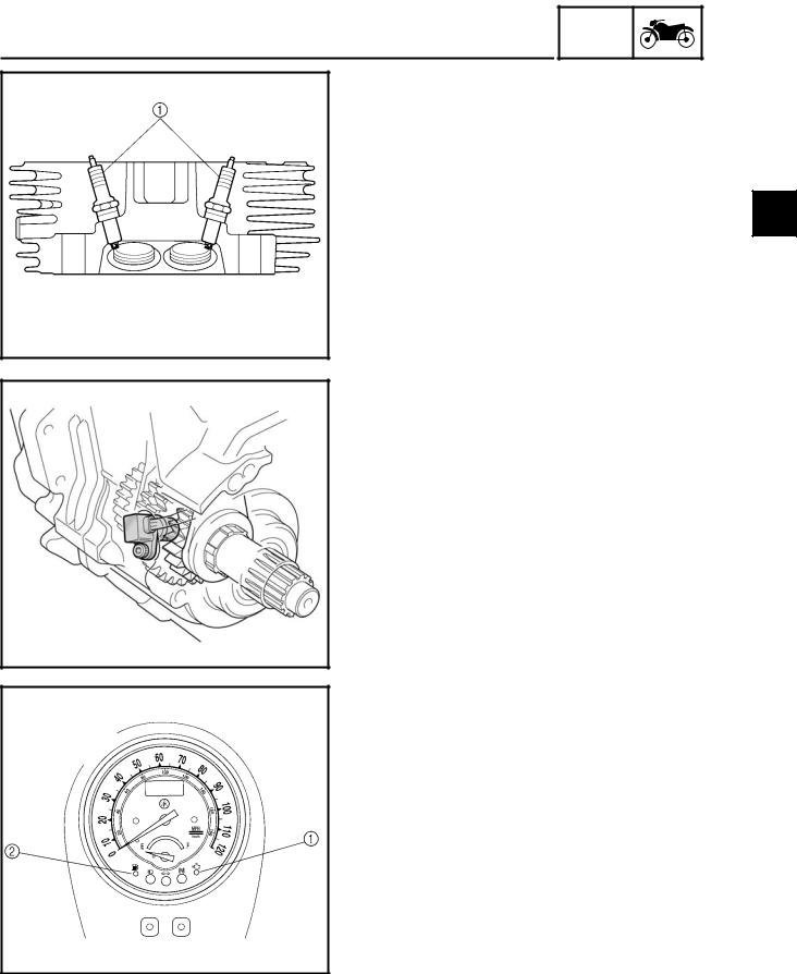
Twin spark plugs |
|
|
For this model, two spark plugs are incor- |
|
|
porated in each cylinder. |
|
|
By using two spark plugs, the combustion |
1 |
|
time in the combustion chamber is short- |
||
ened in an attempt to improve torque. |
||
|
Speed sensor
The speed sensor is installed to the crankcase and it detects the number of passing gears while the vehicle is running in 5th gear and sends the information out as an electrical signal to the ignitor unit.
Self-diagnosis device
This model is equipped with a self-diagno- sis device that has four functions.
The engine trouble indicator light will come on or flash if trouble occurs in an engine monitoring circuit.
|
|
Num- |
Circuit |
Indicator lights |
ber of |
|
|
flashes |
|
|
|
Throttle |
Engine trouble indica- |
3 |
position |
tor light 1 |
|
sensor |
|
|
|
|
|
Speed |
Engine trouble indica- |
4 |
sensor |
tor light 1 |
|
|
|
|
Solenoid |
Engine trouble indica- |
6 |
|
tor light 1 |
|
|
|
|
Fuel level |
Fuel level indicator light |
8 |
meter |
2 |
|
|
|
|
1 - 2 Refer to “SELF-DIAGNOSIS” in chapter 7.
FEATURES
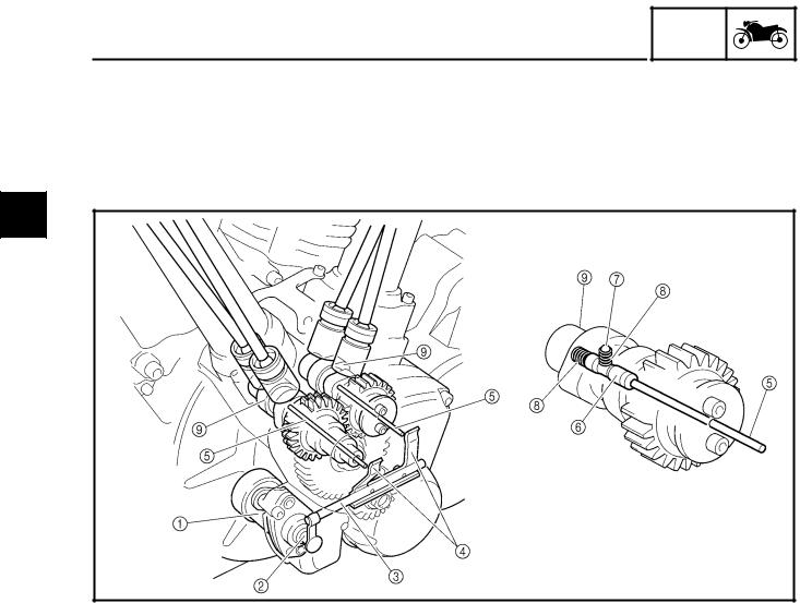
Auto decompression mechanism
GEN INFO
The auto decompression mechanism occurs when the engine is started. When the engine is started, the decompression cam and pin raise the exhaust valve lifters, push the push rods, move the rocker arms, and lower the exhaust valves which compress the cylinder. When the cylinder is compressed, pressure is released immediately, resulting in smoother engine starting capabilities and smoother crankshaft revolutions.
1
1Decompression solenoid
2Decompression solenoid rod
3Decompression connector
4Decompression lever
5Decompression push rod
6Decompression cam
7Pin
8Spring
9Camshaft
1 - 3

FEATURES
Operation
GEN INFO
1. When the starter switch is pushed, elec- |
|
|
tricity is run to the decompression sole- |
|
|
noid 1 causing it to push out the |
|
|
decompression solenoid rod 2. |
|
|
2. When the decompression solenoid rod is |
|
|
pushed out, the decompression connec- |
|
|
1 |
||
tor 3 moves the decompression levers |
||
|
||
4 in the direction indicated by the |
|
|
|
||
arrows, and then the levers push the |
|
|
decompression rods 5 toward the cam- |
|
|
shaft side. |
|
3.The decompression cam 6 is pushed in the direction indicated by the arrow, and then the pin 7 raises the projection of the decompression cam.
4.When the camshaft is rotated by the selftiming motor, the exhaust valve lifters 8 are lifted by the pin just before top dead center (TDC) and the exhaust valve push rod 9 and valve rocker arms are operated. Thus, opening the exhaust valve becomes easy.
5.When the engine starts and reaches a specific engine speed the decompression solenoid is turned off and the decompression system stops operating.
1 - 4
FEATURES
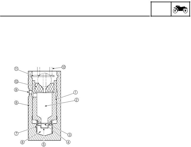
Hydraulic valve lifters
GEN INFO
|
|
Since the hydraulic valve-lifting mechanism maintains a valve clearance of zero, periodic |
|
|
|
valve clearance adjustments are unnecessary. |
|
|
|
The advantages of this system as compared to conventional techniques include the follow- |
|
|
|
ing: mechanical noise is reduced, the camshaft action on the valves remains unaffected by |
|
|
|
engine speed or temperature, and the valve timing is kept stable. |
|
|
|
|
|
1 |
|
|
1Plunger |
|
|||
|
|
|
|
|
|
|
2Oil reservoir |
|
|
|
3Check valve spring |
|
|
|
4Check valve |
|
|
|
5Spring retainer |
|
|
|
6High-pressure chamber |
|
|
|
7Plunger spring |
|
|
|
8Valve lifter body |
|
|
|
9Oil supply inlet |
|
|
|
0Push rod cup |
|
|
|
APlunger retaining clip |
|
|
|
BValve push rod |
|
|
|
|
The hydraulic valve-lifting system functions as follows:
1.As the camshaft rotates, the valve lifter is pushed up by the passing cam lobe.
2.Since the check valve 4 prevents the engine oil contained inside the high-pressure chamber from escaping, the plunger 1 moves up along with the valve lifter body 8 and pushes up the push rod, causing the valve to be lifted.
3.As the camshaft continues to rotate, the valve lifter moves back down to its original posi-
tion, where it remains while the cam heel passes.
When a positive valve clearance is caused by either heat expansion of the cylinder head or engine oil leaking from the valve lifter during stage 2, the plunger, which no longer receives pressure from the push rod, is pushed up by the plunger spring 7. As a result, the valve clearance is zeroed and engine oil is allowed to return to the high-pressure chamber from the reservoir 2 through the check valve 4.
When, on the contrary, a negative valve clearance occurs (this is the case when the cam heel is passing the valve lifter, but the rocker arm, pushed by the push rod, is lifting the valve), the plunger 1 continues to receive pressure from the valve push rod. As engine oil contained inside the high-pressure chamber leaks from the gaps between the valve lifter body 8 and the plunger 1 as well as between the valve lifter body 8 and the check valve 4, the plunger 1 moves down and the valve clearance is zeroed.
1 - 5

GEN
IMPORTANT INFORMATION INFO
EAS00020
IMPORTANT INFORMATION
PREPARATION FOR REMOVAL AND |
|
DISASSEMBLY |
|
1. Before removal and disassembly, |
|
remove all dirt, mud, dust, and foreign |
1 |
material. |
|
|
2.Use only the proper tools and cleaning equipment.
Refer to “SPECIAL TOOLS”.
3.When disassembling, always keep mated parts together. This includes gears, cylinders, pistons, and other parts that have been “mated” through normal wear. Mated parts must always be reused or replaced as an assembly.
4.During disassembly, clean all of the parts and place them in trays in the order of disassembly. This will speed up assembly and allow for the correct installation of all parts.
5.Keep all parts away from any source of fire.
EAS00021
REPLACEMENT PARTS
Use only genuine Yamaha parts for all replacements. Use oil and grease recommended by Yamaha for all lubrication jobs. Other brands may be similar in function and appearance, but inferior in quality.
EAS00022
GASKETS, OIL SEALS AND O-RINGS
1.When overhauling the engine, replace all gaskets, seals, and O-rings. All gasket surfaces, oil seal lips, and O-rings must be cleaned.
2.During reassembly, properly oil all mating parts and bearings and lubricate the oil seal lips with grease.
1 - 6
|
|
|
|
|
|
|
|
|
|
|
|
|
IMPORTANT INFORMATION |
|
GEN |
|
|
||||
|
|
|
INFO |
|
|
|||||
|
|
|
|
|
|
|
|
|
|
|
|
|
|
|
EAS00023 |
||||||
|
|
|
|
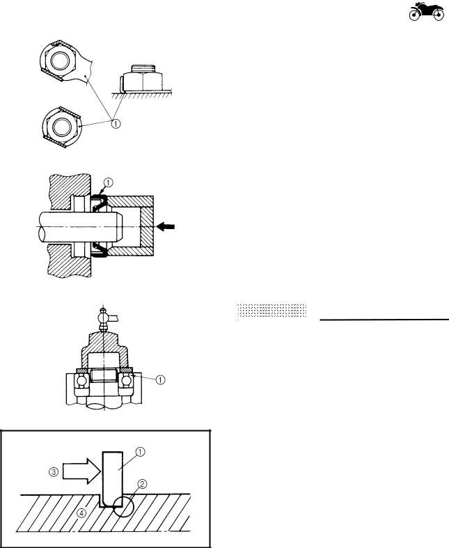
LOCK WASHERS/PLATES AND COTTER |
||||||
|
|
|
|
PINS |
||||||
|
|
|
|
After removal, replace all lock washers/ |
||||||
|
|
|
|
plates 1 and cotter pins. After the bolt or |
||||||
|
|
|
|
nut has been tightened to specification, |
||||||
|
|
|
|
bend the lock washer tabs and the cotter |
||||||
1 |
|
|
|
|||||||
|
|
|
pin ends along a flat of the bolt or nut. |
|||||||
|
|
|
|
|||||||
|
|
|
|
EAS00024 |
||||||
|
|
|
|
|||||||
|
|
|
|
|||||||
|
|
|
|
BEARINGS AND OIL SEALS |
||||||
|
|
|
|
1. Install bearings and oil seals so that the |
||||||
|
|
|
|
manufacturer’s marks or numbers are |
||||||
|
|
|
|
visible. When installing oil seals, lubri- |
||||||
|
|
|
|
cate the oil seal lips with a light coat of |
||||||
|
|
|
|
lithium soap base grease. Oil bearings |
||||||
|
|
|
|
liberally when installing, if appropriate. |
||||||
|
|
|
|
1Oil seal |
||||||
|
|
|
|
|
|
|
|
|||
|
|
|
|
|
|
|
|
|||
|
|
|
|
CAUTION: |
|
|
|
|
|
|
|
|
|
|
|
|
|
||||
|
|
|
|
ACHTUNG: |
|
|
|
|||
|
|
|
|
|
|
|
|
|||
|
|
|
|
Do not spin bearings with compressed air |
||||||
|
|
|
|
because this will damage the bearing sur- |
||||||
|
|
|
|
faces. |
||||||
|
|
|
|
|
|
|||||
|
|
|
|
1Bearing |
||||||
|
|
|
|
|
|
|
|
|
|
|
EAS00025
CIRCLIPS
Before reassembly, check all circlips carefully and replace damaged or distorted circlips. Always replace piston pin clips after one use. When installing a circlip 1, make sure the sharp-edged corner 2 is positioned opposite the thrust 3 that the circlip receives.
4Shaft
1 - 7
CHECKING THE CONNECTIONS
EAS00026
GEN INFO
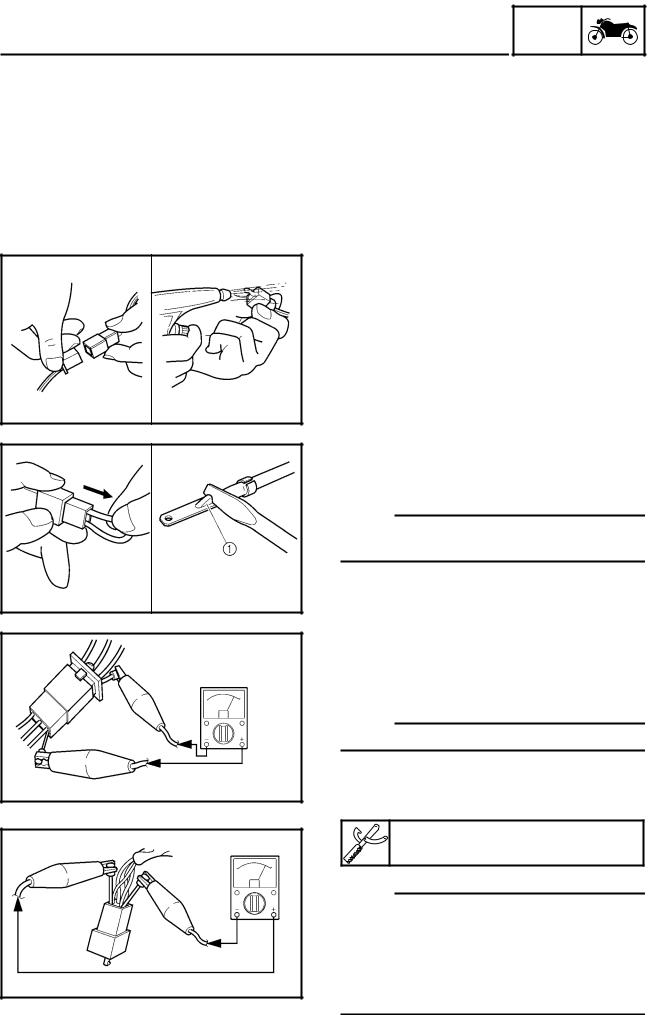
CHECKING THE CONNECTIONS
Check the leads, couplers, and connectors for stains, rust, moisture, etc.
1. |
Disconnect: |
|
|
• lead |
|
||
1 |
|||
• coupler |
|||
• connector |
|||
2. |
Check: |
|
|
• lead |
|
||
• coupler |
|
||
• connector |
|
||
|
Moisture → Dry with an air blower. |
|
|
|
Rust/stains → Connect and disconnect |
|
|
|
several times. |
|
|
3. |
Check: |
|
|
• all connections |
|
||
|
Loose connection → Connect properly. |
|
|
NOTE:
If the pin 1 on the terminal is flattened, bend it up.
4.Connect:
•lead
•coupler
•connector
NOTE:
Make sure all connections are tight.
5.Check:
•continuity
(with the pocket tester)
Pocket tester
YU-03112
NOTE:
•If there is no continuity, clean the terminals.
•When checking the wire harness, perform steps (1) to (3).
•As a quick remedy, use a contact revitalizer available at most part stores.
1 - 8
SPECIAL TOOLS
EAS00027
GEN INFO
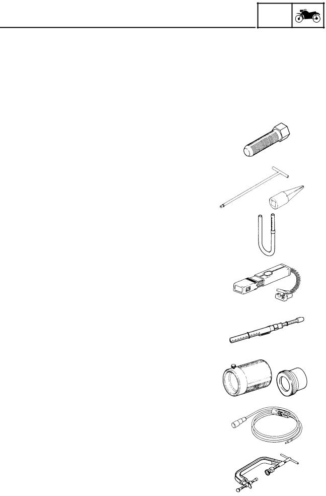
SPECIAL TOOLS
|
|
The following special tools are necessary for complete and accurate tune-up and assembly. |
|||
|
|
Use only the appropriate special tools as this will help prevent damage caused by the use of |
|||
|
|
inappropriate tools or improvised techniques. Special tools, part numbers, or both may differ |
|||
|
|
depending on the country. |
|
||
1 |
|
When placing an order, refer to the list provided below to avoid any mistakes. |
|||
|
|
|
|
||
Tool No. |
Tool name/Function |
Illustration |
|||
|
|
||||
|
|
|
|
|
|
|
|
YM-01080-A |
Flywheel puller |
|
|
|
|
|
This tool is used to remove the generator |
|
|
|
|
|
rotor. |
|
|
|
|
T-handle |
T-handle |
|
|
|
|
YM-01326 |
Damper rod holder |
|
|
|
|
Damper rod |
These tools are used to hold the cartridge |
|
|
|
|
holder |
cylinder when loosening or tightening the |
|
|
|
|
YM-1300-1 |
cartridge cylinder bolt. |
|
|
|
|
|
|
|
|
|
|
|
Fuel level gauge |
|
|
|
|
YM-01312-A |
|
|
|
|
|
|
This tool is used to measure the fuel level |
|
|
|
|
|
in the float chamber. |
|
|
|
|
|
|
|
|
|
|
|
Timing light |
|
|
|
|
YM-33277-A |
|
|
|
|
|
|
This tool is used to check the ignition tim- |
|
|
|
|
|
ing. |
|
|
|
|
|
|
|
|
|
|
|
Belt tension gauge |
|
|
|
|
YM-03170 |
|
|
|
|
|
|
This tool is used to measure the drive belt |
|
|
|
|
|
slack. |
|
|
|
|
|
|
|
|
|
|
Fork seal |
Fork seal driver weight |
|
|
|
|
driver weight |
Adapter |
|
|
|
|
YM-33963 |
These tools are used to install the front |
|
|
|
|
Adapter |
|
||
|
|
YM-8020 |
fork’s oil seal and dust seal. |
|
|
|
|
|
|
|
|
|
|
|
Dynamic spark tester |
|
|
|
|
YM-34487 |
|
|
|
|
|
|
This tool is used to check the ignition sys- |
|
|
|
|
|
tem components. |
|
|
|
|
|
|
|
|
|
|
|
Valve spring compressor |
|
|
|
|
YM-04019 |
|
|
|
|
|
|
This tool is used to remove or install the |
|
|
|
|
|
valve assemblies. |
|
|
|
|
|
|
|
|
|
|
|
1 - 9 |
|
|
|
|
|
|
|
|
|
|
|
|
SPECIAL TOOLS |
|
GEN |
|
|
|
|
|
|
|
INFO |
|
|
|
|
||
|
|
|
|
|
|
|
|
|
|
|
|
|
|
||||
Tool No. |
Tool name/Function |
Illustration |
|
|
|
|||
|
|
|
|
|
|
|
|
|
|
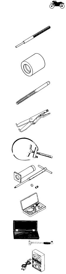
Valve guide remover (6 mm) |
|
|
|
|
|
|
|
YM-4064-A |
|
|
|
|
|
|
|
|
|
This tool is used to remove or install the |
|
|
|
|
|
|
|
|
valve guides. |
|
|
|
|
|
|
|
|
|
|
|
|
|
|
1 |
|
|
|
|
|
|||||
|
Valve guide installer |
|
|
|
|
|||
|
|
|
|
|
|
|
|
|
YM-4065-A |
|
|
|
|
|
|
|
|
|
|
|
|
|
|
|
|
|
|
This tool is used to install the valve |
|
|
|
|
|
|
|
|
guides. |
|
|
|
|
|
|
|
|
|
|
|
|
|
|
|
|
|
Valve guide reamer |
|
|
|
|
|
|
|
YM-4066 |
|
|
|
|
|
|
|
|
|
This tool is used to rebore the new valve |
|
|
|
|
|
|
|
|
guides. |
|
|
|
|
|
|
|
|
|
|
|
|
|
|
|
|
|
Universal clutch holder |
|
|
|
|
|
|
|
YM-91042 |
This tool is used to hold the clutch boss |
|
|
|
|
|
|
|
|
when removing or installing the clutch |
|
|
|
|
|
|
|
|
boss nut. |
|
|
|
|
|
|
|
|
|
|
|
|
|
|
|
|
|
Sheave holder |
|
|
|
|
|
|
|
YS-01880 |
This tool is used to hold the generator |
|
|
|
|
|
|
|
rotor when removing or installing the gen- |
|
|
|
|
|
|
|
|
|
erator rotor bolt, generator shaft bolt or |
|
|
|
|
|
|
|
|
pickup coil rotor bolt. |
|
|
|
|
|
|
|
|
|
|
|
|
|
|
|
|
|
Piston pin puller |
|
|
|
|
|
|
|
YU-01304 |
|
|
|
|
|
|
|
|
|
This tool is used to remove the piston |
|
|
|
|
|
|
|
|
pins. |
|
|
|
|
|
|
|
|
|
|
|
|
|
|
|
|
|
Micrometer (75 ~ 100 mm) |
|
|
|
|
|
|
|
YU-03009 |
|
|
|
|
|
|
|
|
|
This tool is used to measure the piston |
|
|
|
|
|
|
|
|
skirt diameter. |
|
|
|
|
|
|
|
|
|
|
|
|
|
|
|
|
|
Cylinder bore gauge (50 ~ 100 mm) |
|
|
|
|
|
|
|
YU-03017 |
|
|
|
|
|
|
|
|
|
This tool is used to measure the cylinder |
|
|
|
|
|
|
|
|
bore. |
|
|
|
|
|
|
|
|
|
|
|
|
|
|
|
|
|
Pocket tester |
|
|
|
|
|
|
|
YU-03112 |
|
|
|
|
|
|
|
|
|
This tool is used to check the electrical |
|
|
|
|
|
|
|
|
system. |
|
|
|
|
|
|
|
|
|
|
|
|
|
|
|
|
1 - 10
|
|
|
|
|
|
|
|
|
|
|
|
SPECIAL TOOLS |
|
GEN |
|
|
|
|
|
|
|
INFO |
|
|
||
|
|
|
|
|
|
|
|
|
|
|
|
|
|
|
|||
|
|
Tool No. |
Tool name/Function |
Illustration |
|
|||
|
|
|
|
|
|
|
|
|
|
|
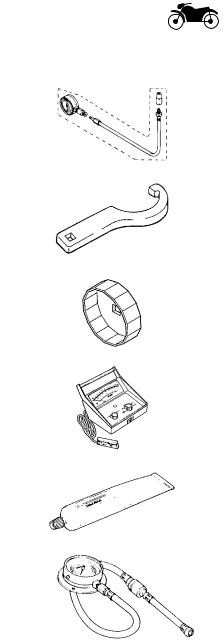
Compression |
Compression gauge |
|
|
|
|
|
|
|
gauge |
|
|
|
|
|
|
|
|
YU-33223 |
|
|
|
|
|
|
|
|
Compression |
These tools are used to measure engine |
|
|
|
|
|
|
|
gauge adapter |
|
|
|
|
|
|
|
|
YU-33223-3 |
compression. |
|
|
|
|
|
1 |
|
|
|
|
|
|
||
|
|
|
|
|
|
|
|
|
|
Steering nut wrench |
|
|
|
|
|
||
|
|
|
|
|
|
|
|
|
|
|
YU-33975 |
|
|
|
|
|
|
|
|
|
|
|
|
|
|
|
|
|
|
This tool is used to loosen or tighten the |
|
|
|
|
|
|
|
|
steering stem ring nuts. |
|
|
|
|
|
|
|
|
|
|
|
|
|
|
|
|
|
Oil filter wrench |
|
|
|
|
|
|
|
YU-38411 |
|
|
|
|
|
|
|
|
|
This tool is needed to loosen or tighten |
|
|
|
|
|
|
|
|
the oil filter cartridge. |
|
|
|
|
|
|
|
|
|
|
|
|
|
|
|
|
|
Inductive tachometer |
|
|
|
|
|
|
|
YU-8036-A |
|
|
|
|
|
|
|
|
|
This tool is used to check engine speed. |
|
|
|
|
|
|
|
|
|
|
|
|
|
|
|
|
|
Quick Gasket |
|
|
|
|
|
|
|
ACC-11001-05- |
This sealant is used to seal two mating |
|
|
|
|
|
|
|
01 |
|
|
|
|
|
|
|
|
surfaces (e. g., crankcase mating sur- |
|
|
|
|
|
|
|
|
|
|
|
|
|
|
|
|
|
|
faces). |
|
|
|
|
|
|
|
|
|
|
|
|
|
|
|
|
|
Oil pressure gauge |
|
|
|
|
|
|
|
90890-03153 |
|
|
|
|
|
|
|
|
|
This tool is used to measure the engine oil |
|
|
|
|
|
|
|
|
pressure. |
|
|
|
|
|
|
|
|
|
|
|
|
|
|
1 - 11

|
|
|
|
|
|
|
|
|
|
|
|
|
|
|
|
SPEC |
|
|
|
|
|
|
|
|
|
|
|
CONTENTS |
|
|
|
|
|
|
|
|
|
|
|
|
|
|
|
|
|
|
|
|
SPECIFICATIONS |
|
|
|
|
|
|
GENERAL SPECIFICATIONS ....................................................................... |
2-1 |
|
|
|
|
|
ENGINE SPECIFICATIONS ........................................................................... |
2-2 |
|
|
|
|
|
CHASSIS SPECIFICATIONS ....................................................................... |
2-11 |
|
|
|
|
|
|
|
|
|
|
|
|
ELECTRICAL SPECIFICATIONS |
2-15 |
|
|
|
2 |
|
|
|
|
|
|||
TIGHTENING TORQUES |
2-18 |
|
|
|
|
|
|
|
|
|
|||
GENERAL TIGHTENING TORQUES .................................................. |
2-18 |
|
|
|
|
|
ENGINE TIGHTENING TORQUES ..................................................... |
2-19 |
|
|
|
|
|
CHASSIS TIGHTENING TORQUES ................................................... |
2-21 |
|
|
|
|
|
LUBRICATION POINTS AND LUBRICANT TYPES ................................... |
2-23 |
|
|
|
|
|
ENGINE LUBRICATION POINTS AND LUBRICANT TYPES ............ |
2-23 |
|
|
|
|
|
CHASSIS LUBRICATION POINTS AND LUBRICANT TYPES .......... |
2-24 |
|
|
|
|
|
ENGINE OIL LUBRICATION CHART .......................................................... |
2-25 |
|
|
|
|
|
ENGINE OIL FLOW DIAGRAMS ................................................................ |
2-26 |
|
|
|
|
|
TRANSFER GEAR OIL FLOW DIAGRAMS ................................................ |
2-30 |
|
|
|
|
|
CABLE ROUTING ....................................................................................... |
2-32 |
|
|
|
|
|

|
|
|
|
|
|
|
|
|
|
|
|
|
|
|
|
|
|
GENERAL SPECIFICATIONS |
|
SPEC |
|
||
|
|
|
|
|
|
|
|
|
|
SPECIFICATIONS |
|
|
|
|
|
|
|
|
|
|
|
||
|
|
GENERAL SPECIFICATIONS |
|
|
|
|
|
|
|
|
|
|
|
|
|
|
|
Item |
Standard |
|
|
Limit |
|
|
|
|
|
|
|
|
|
|
|
Dimensions |
|
|
|
|
|
|
|
Overall length |
2,500 mm (98.4 in) |
|
---- |
||
|
|
Overall width |
980 mm (38.6 in) |
|
---- |
||
|
|
Overall height |
1,140 mm (44.9 in): XV16A |
|
---- |
||
|
|
|
1,500 mm (59.1 in): XV16AT |
|
---- |
||
|
|
Seat height |
710 mm (28.0 in) |
|
---- |
||
2 |
|
Wheelbase |
1,685 mm (66.3 in) |
|
|
---- |
|
|
Minimum ground clearance |
145 mm (5.71 in) |
|
---- |
|||
|
|
Minimum turning radius |
3,200 mm (126 in) |
|
|
---- |
|
|
|
|
|
|
|
|
|
|
|
Weight |
|
|
|
|
|
|
|
Wet (with oil and a full fuel tank) |
332 kg (732 lb): XV16A |
|
---- |
||
|
|
|
347 kg (765 lb): XV16AT |
|
---- |
||
|
|
Dry (without oil and fuel) |
307 kg (678 lb): XV16A |
|
---- |
||
|
|
|
322 kg (710 lb): XV16AT |
|
---- |
||
|
|
Maximum load (total of cargo, rider, |
196 kg (432 lb): XV16A |
|
---- |
||
|
|
passenger, and accessories) |
181 kg (399 lb): XV16AT |
|
---- |
||
2 - 1
ENGINE SPECIFICATIONS SPEC
ENGINE SPECIFICATIONS
|
|
|
|
|
Item |
|
|
|
|
Standard |
Limit |
|
|
||
|
|
|
|
|
|
|
|
|
|
|
|
|
|
|
|
Engine |
|
|
|
|
|
|
|
|
|
|
|
|
|
||
|
Engine type |
|
|
|
|
|
|
Air-cooled, 4-stroke, OHV |
---- |
|
|
||||
|
Displacement |
|
|
|
|
|
|
1,602 cm3 |
---- |
|
|
||||
|
Cylinder arrangement |
|
|
|
|
V-type 2-cylinder |
---- |
|
|
||||||
|
Bore × stroke |
|
|
|
|
|
|
95 × 113 mm (3.74 × 4.45 in) |
---- |
|
|
||||
|
Compression ratio |
|
|
|
|
8.3:1 |
---- |
|
|
||||||
|
Engine idling speed |
|
|
|
|
850 ~ 950 r/min |
---- |
|
|
||||||
|
Vacuum pressure at engine idling |
52 kPa (390 mm Hg, 15.4 in Hg) |
---- |
|
|
||||||||||
|
|
2 |
|||||||||||||
|
speed |
|
|
|
|
|
|
|
|
|
|
|
|
||
|
Standard compression pressure |
1,200 kPa |
---- |
|
|||||||||||
|
|
|
|||||||||||||
|
(at sea level) |
|
|
|
|
|
|
(12.0 kgf/cm2, 171 psi) at 200 r/min |
|
|
|
||||
Fuel |
|
|
|
|
|
|
|
|
|
|
|
|
|
||
|
Recommended fuel |
|
|
|
|
Unleaded fuel (for USA) |
---- |
|
|
||||||
|
|
|
|
|
|
|
|
|
|
|
|
Regular unleaded gasoline (for CDN) |
---- |
|
|
|
Fuel tank capacity |
|
|
|
|
|
|
|
|
||||||
|
Total (including reserve) |
20 L (17.6 Imp qt, 21.1 US qt) |
---- |
|
|
||||||||||
|
Reserve only |
|
|
|
|
|
|
3.5 L (3.08 Imp qt, 3.70 US qt) |
---- |
|
|
||||
|
|
|
|
|
|
|
|
|
|
|
|
|
|
|
|
Engine oil |
|
|
|
|
|
|
|
|
|
|
|
|
|
||
|
Lubrication system |
|
|
|
|
Dry sump |
---- |
|
|
||||||
|
Recommended oil |
|
|
|
|
|
---- |
|
|
||||||
|
|
|
|
|
|
|
|
|
|
|
|
|
|
||
|
30 |
40 |
50 |
60˚F |
|
Yamalube 4 (20W40) or SAE 20W40 type |
|
|
|
||||||
|
|
|
|
|
|
|
|
|
|
|
|
|
|
|
|
|
|
|
|
|
|
|
|
|
|
|
|
SE motor oil (40˚F/5˚C or above) |
|
|
|
|
|
|
|
|
|
|
|
|
|
|
|
|
|
|
|
|
|
|
|
|
|
|
|
|
|
|
|
(Non-Friction modified) |
|
|
|
|
|
|
|
|
|
|
|
|
|
|
|
|
|
|
|
|
0 |
5 |
|
10 |
15˚C |
|
|
|
|
|
|||||
|
Quantity |
|
|
|
|
|
|
|
|
|
|
|
|
|
|
|
Total amount |
|
|
|
|
|
|
5.0 L (4.4 Imp qt, 5.3 US qt) |
---- |
|
|
||||
|
Without oil filter cartridge |
3.7 L (3.3 Imp qt, 3.9 US qt) |
---- |
|
|
||||||||||
|
replacement |
|
|
|
|
|
|
|
|
|
|
||||
|
With oil filter cartridge replace- |
4.1 L (3.6 Imp qt, 4.3 US qt) |
---- |
|
|
||||||||||
|
ment |
|
|
|
|
|
|
|
|
|
|
|
|
|
|
|
Oil pressure (hot) |
|
|
|
|
|
|
60 kPa (0.6 kgf/cm2, 8.5 psi) at 900 r/min |
---- |
|
|
||||
|
Relief valve opening pressure |
0.60 MPa (6.0 kgf/cm2, 85 psi) |
---- |
|
|
||||||||||
Transfer gear oil |
|
|
|
|
|
|
|
|
|
|
|||||
|
Recommended oil |
|
|
|
|
SAE80API “GL-4” hypoid gear oil |
---- |
|
|
||||||
|
Quantity |
|
|
|
|
|
|
|
|
|
0.4 L (0.35 Imp qt, 0.42 US qt) |
---- |
|
|
|
|
|
|
|
|
|
|
|
|
|
|
|
|
|
|
|
Oil filter |
|
|
|
|
|
|
|
|
|
|
|
|
|
||
|
Oil filter type |
|
|
|
|
|
|
Cartridge (paper) |
---- |
|
|
||||
|
Bypass valve opening pressure |
80 ~ 120 kPa |
---- |
|
|
||||||||||
|
|
|
|
|
|
|
|
|
|
|
|
(0.8 ~ 1.2 kgf/cm2, 11.3 ~ 17.1 psi) |
|
|
|
2 - 2
ENGINE SPECIFICATIONS SPEC
|
|
Item |
Standard |
Limit |
|||
|
|
|
|
|
|
|
|
|
|
Engine oil pump |
|
|
|||
|
|
Oil pump type |
Trochoidal |
---- |
|||
|
|
Inner rotor to outer rotor tip clear- |
0.00 ~ 0.12 mm (0.000 ~ 0.005 in) |
0.17 mm |
|||
|
|
ance |
|
(0.007 in) |
|||
|
|
Inner rotor outer rotor 2 to oil pump |
0.03 ~ 0.08 mm (0.001 ~ 0.003 in) |
0.13 mm |
|||
|
|
housing clearance (feed pump) |
|
(0.005 in) |
|||
|
|
Inner rotor outer rotor 1 to oil |
0.06 ~ 0.11 mm (0.002 ~ 0.004 in) |
0.16 mm |
|||
|
|
pump housing clearance |
|
(0.006 in) |
|||
|
|
(scavenging pump) |
|
|
|||
|
|
|
|
|
|
|
|
|
|
Transfer oil pump |
|
|
|||
2 |
|
|
|
||||
|
Oil pump type |
Trochoidal |
|
||||
|
|
|
|||||
|
|
Inner rotor to outer rotor tip clear- |
0.07 ~ 0.12 mm (0.003 ~ 0.005 in) |
0.17 mm |
|||
|
|
||||||
|
|
ance |
|
(0.007 in) |
|||
|
|
Inner rotor outer rotor to oil pump |
0.03 ~ 0.08 mm (0.001 ~ 0.003 in) |
0.16 mm |
|||
|
|
housing clearance |
|
(0.006 in) |
|||
|
|
|
|
|
|
|
|
|
|
Starting system type |
Electric starter |
|
|||
|
|
|
|
|
|
|
|
|
|
Spark plugs |
|
|
|||
|
|
Model |
DPR7EA-9/X22EPR-U9 |
---- |
|||
|
|
Manufacturer |
NGK/DENSO |
---- |
|||
|
|
Quantity |
4 |
---- |
|||
|
|
Spark plug gap |
0.8 ~ 0.9 mm (0.031 ~ 0.035 in) |
---- |
|||
|
|
|
|
|
|
|
|
|
|
Cylinder heads |
|
|
|||
|
|
Max. warpage |
---- |
0.10 mm |
|||
|
|
|
|
|
|
|
(0.004 in) |
|
|
|
|
|
|
|
|
|
|
Camshafts |
|
|
|||
|
|
Drive system |
Gear drive |
---- |
|||
|
|
Crankcase hole inside diameter |
25.000 ~ 25.021 mm |
---- |
|||
|
|
|
|
|
|
(0.9843 ~ 0.9851 in) |
|
|
|
|
|
|
|
|
|
|
|
Camshaft cover hole inside diam- |
28.000 ~ 28.021 mm |
---- |
|||
|
|
eter |
(1.1024 ~ 1.1032 in) |
||||
|
|
|
|||||
|
|
Camshaft journal diameter |
24.937 ~ 24.950 mm |
---- |
|||
|
|
(crankcase side) |
(0.9818 ~ 0.9823 in) |
||||
|
|
|
|||||
|
|
Camshaft journal diameter |
27.967 ~ 27.980 mm |
---- |
|||
|
|
(camshaft cover side) |
(1.1011 ~ 1.1016 in) |
||||
|
|
|
|||||
|
|
Camshaft to crankcase clearance |
0.050 ~ 0.084 mm (0.0020 ~ 0.0033 in) |
---- |
|||
|
|
Camshaft to camshaft cover clear- |
0.020 ~ 0.054 mm (0.0008 ~ 0.0021 in) |
---- |
|||
|
|
ance |
|
|
|||
|
|
Camshaft intake cam dimensions |
|
|
|||
|
|
|
|
|
|
|
|
|
|
|
|
|
|
|
|
A
B
2 - 3
|
|
|
|
|
|
|
|
|
|
|
|
|
|
|
|
|
|
|
|
|
|
|
|
|
|
|
|
|
|
|
|
|
|
|
|
|
|
|
|
|
|
|
|
|
|
|
|
|
|
|
|
|
|
|
|
|
|
ENGINE SPECIFICATIONS |
|
|
SPEC |
|
|
|
|
|
|
|
|
|
|
|
|
|
|
|
|
|
|
|
|
|
|
|
|
|
|
|
|
|
|
|
|
|
|
|
|
|
|
|
|
|
|
|
|
|
|
|
|
|
|
|
Item |
|
|
|
|
|
Standard |
|
|
|
Limit |
|
|
||||||
|
|
|
|
|
|
|
|
|
|
|
|
|
|
|
|
|
|
|
|
|
|
Measurement A |
|
|
|
|
|
36.594 ~ 36.649 mm |
|
|
|
36.494 mm |
|
|
|||||||||
|
|
|
|
|
|
|
|
|
|
|
|
|
|
(1.4407 ~ 1.4429 in) |
|
|
|
(1.4368 in) |
|
|
|
Measurement B |
|
|
|
|
|
31.950 ~ 32.050 mm |
|
|
|
31.850 mm |
|
|
|||||||||
|
|
|
|
|
|
|
|
|
|
|
|
|
|
(1.2579 ~ 1.2618 in) |
|
|
|
(1.2539 in) |
|
|
|
Camshaft exhaust cam dimen- |
|
|
|
|
|
|
|
|
|
||||||||||||
sions |
|
|
|
|
|
|
|
|
|
|
|
|
|
||||||||
|
|
|
|
|
|
|
|
|
|
|
|
|
|
|
|
|
|
|
|
|
|
|
|
|
|
|
|
|
|
|
|
|
|
|
|
|
|
|
|
|
|
|
|
|
|
|
|
|
|
|
|
|
|
A |
|
|
|
|
|
|
|
|
|
|
|
|
|
|
|
|
|
|
|
|
|
|
|
|
|
|
|
|
|
|
2 |
||
|
|
|
|
|
|
|
|
|
|
|
|
|
|
|
|
|
|
|
|
|
|
|
|
|
|
|
|
|
|
|
|
|
|
|
|
|
|
|
|
|
|
||
|
|
|
|
|
|
|
|
|
|
|
|
|
|
|
|
|
|
|
|
|
|
|
|
|
|
|
|
B |
|
|
|
|
|
|
|
|
|
|
|
|
|
|
|
|
|
|
|
|
|
|
|
|
|
|
|
|
|
|
|
|
|
|
|
||
Measurement A |
|
|
|
|
|
36.554 ~ 36.654 mm |
|
|
|
36.454 mm |
|
|
|||||||||
|
|
|
|
|
|
|
|
|
|
|
|
|
|
(1.4391~ 1.4431 in) |
|
|
|
(1.4352 in) |
|
|
|
Measurement B |
|
|
|
|
|
31.950 ~ 32.050 mm |
|
|
|
31.850 mm |
|
|
|||||||||
|
|
|
|
|
|
|
|
|
|
|
|
|
|
(1.2579 ~ 1.2618 in) |
|
|
|
(1.2539 in) |
|
|
|
|
|
|
|
|
|
|
|
|
|
|
|
|
|
|
|
|
|
|
|
|
|
Rocker arms, Rocker arm shafts |
|
|
|
|
|
|
|
|
|
||||||||||||
Rocker arm inside diameter |
|
15.000 ~ 15.018 mm |
|
|
|
15.036 mm |
|
|
|||||||||||||
|
|
|
|
|
|
|
|
|
|
|
|
|
|
(0.5906 ~ 0.5913 in) |
|
|
|
(0.5920 in) |
|
|
|
Rocker arm shaft outside diameter |
|
14.981 ~ 14.991 mm |
|
|
|
14.97 mm |
|
|
|||||||||||||
|
|
|
|
|
|
|
|
|
|
|
|
|
|
(0.5898 ~ 0.5902 in) |
|
|
|
(0.5894 in) |
|
|
|
Rocker arm to rocker arm shaft |
|
0.009 ~ 0.037 mm (0.0004 ~ 0.0015 in) |
0.08 mm |
|
|
||||||||||||||||
clearance |
|
|
|
|
|
|
|
|
|
(0.003 in) |
|
|
|||||||||
|
|
|
|
|
|
|
|
|
|
|
|
|
|
|
|
|
|
|
|
|
|
Valves, valve seats, valve guides |
|
|
|
|
|
|
|
|
|
||||||||||||
Valve clearance (cold) |
|
|
|
|
|
|
|
|
|
|
|
|
|
||||||||
Intake |
|
|
|
|
|
0 ~ 0.04 mm (0 ~ 0.0016 in) |
|
|
|
---- |
|
|
|||||||||
Exhaust |
|
|
|
|
|
0 ~ 0.04 mm (0 ~ 0.0016 in) |
|
|
|
---- |
|
|
|||||||||
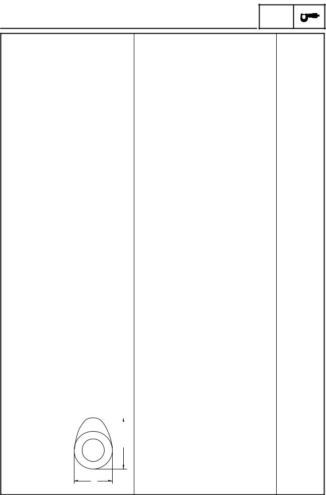
Valve dimensions |
|
|
|
B |
C |
|
|
|
|
|
|
|
|||||||||
|
|
|
|
|
|
|
|
|
|
|
|
|
|
|
|
|
|
|
|||
|
|
A |
|
|
|
|
|
|
|
|
|
|
|
Seat Width |
|
|
|
|
D |
|
|
|
|
|
|
|
|
|
|
|
|
|
|
|
|
|
|
|
|
|
|||
|
|
|
|
|
|
|
|
|
|
|
|
|
|
|
|
||||||
|
|
|
|
|
|
|
|
|
|
|
|
|
|
|
|||||||
Head Diameter |
Face Width |
Margin Thickness |
|
|
|||||||||||||||||
Valve head diameter A |
|
|
|
|
|
|
|
|
|
|
|
|
|
||||||||
|
|
|
|
|
|
|
|
|
|
|
|
|
|||||||||
|
Intake |
|
|
|
|
|
33.9 ~ 34.1 mm (1.3346 ~ 1.3425 in) |
---- |
|
|
|||||||||||
|
Exhaust |
|
|
|
|
|
27.9 ~ 28.1 mm (1.0984 ~ 1.1063 in) |
---- |
|
|
|||||||||||
Valve face width B |
|
|
|
|
|
|
|
|
|
|
|
|
|
||||||||
|
Intake |
|
|
|
|
|
1.3 ~ 2.3 mm (0.0512 ~ 0.0906 in) |
|
|
|
---- |
|
|
||||||||
|
Exhaust |
|
|
|
|
|
1.2 ~ 2.4 mm (0.0472 ~ 0.0945 in) |
|
|
|
---- |
|
|
||||||||
Valve seat width C |
|
|
|
|
|
|
|
|
|
|
|
|
|
||||||||
|
Intake |
|
|
|
|
|
0.9 ~ 1.1 mm (0.035 ~ 0.043 in) |
|
|
|
2.0 mm |
|
|
||||||||
|
|
|
|
|
|
|
|
|
|
|
|
|
|
|
|
|
|
(0.079 in) |
|
|
|
|
Exhaust |
|
|
|
|
|
0.9 ~ 1.1 mm (0.035 ~ 0.043 in) |
|
|
|
2.0 mm |
|
|
||||||||
|
|
|
|
|
|
|
|
|
|
|
|
|
|
|
|
|
|
(0.079 in) |
|
|
|
|
|
|
|
|
|
|
|
|
|
|
|
|
|
|
|
|
|
|
|
|
|
2 - 4
ENGINE SPECIFICATIONS SPEC
|
|
|
|
|
|
|
|
Item |
Standard |
Limit |
||||||||
|
|
|
|
|
|
|
|
|
|
|
|
|
|
|
|
|
|
|
|
|
Valve margin thickness D |
|
|
||||||||||||||
|
|
|
Intake |
0.7 ~ 1.3 mm (0.028 ~ 0.051 in) |
0.4 mm |
|||||||||||||
|
|
|
|
|
|
|
|
|
|
|
|
|
|
|
|
|
|
(0.016 in) |
|
|
|
Exhaust |
0.7 ~ 1.3 mm (0.028 ~ 0.051 in) |
0.4 mm |
|||||||||||||
|
|
|
|
|
|
|
|
|
|
|
|
|
|
|
|
|
|
(0.016 in) |
|
|
Valve stem diameter |
|
|
||||||||||||||
|
|
|
Intake |
5.975 ~ 5.990 mm (0.2352 ~ 0.2358 in) |
5.945 mm |
|||||||||||||
|
|
|
|
|
|
|
|
|
|
|
|
|
|
|
|
|
|
(0.2341 in) |
|
|
|
Exhaust |
5.960 ~ 5.975 mm (0.2346 ~ 0.2352 in) |
5.920 mm |
|||||||||||||
|
|
|
|
|
|
|
|
|
|
|
|
|
|
|
|
|
|
(0.2331 in) |
2 |
|
Valve guide inside diameter |
|
|||||||||||||||
|
|
|
||||||||||||||||
|
|
|
|
|||||||||||||||
|
|
|
Intake |
6.000 ~ 6.012 mm (0.2362 ~ 0.2367 in) |
6.05 mm |
|||||||||||||
|
|
|
||||||||||||||||
|
|
|
|
|
|
|
|
|
|
|
|
|
|
|
|
|
|
(0.2382 in) |
|
|
|
Exhaust |
6.000 ~ 6.012 mm (0.2362 ~ 0.2367 in) |
6.05 mm |
|||||||||||||
|
|
|
|
|
|
|
|
|
|
|
|
|
|
|
|
|
|
(0.2382 in) |
|
|
Valve stem-to-valve guide clear- |
|
|
||||||||||||||
|
|
ance |
|
|
||||||||||||||
|
|
|
Intake |
0.010 ~ 0.037 mm (0.0004 ~ 0.0015 in) |
0.08 mm |
|||||||||||||
|
|
|
|
|
|
|
|
|
|
|
|
|
|
|
|
|
|
(0.0031 in) |
|
|
|
Exhaust |
0.025 ~ 0.052 mm (0.0010 ~ 0.0020 in) |
0.1 mm |
|||||||||||||
|
|
|
|
|
|
|
|
|
|
|
|
|
|
|
|
|
|
(0.004 in) |
|
|
Valve stem runout |
---- |
0.01 mm |
||||||||||||||
|
|
|
|
|
|
|
|
|
|
|
|
|
|
|
|
|
|
(0.0004 in) |
|
|
|
|
|
|
|
|
|
|
|
|
|
|
|
|
|
|
|
|
|
|
|
|
|
|
|
|
|
|
|
|
|
|
|
|
|
|
|
|
|
|
|
|
|
|
|
|
|
|
|
|
|
|
|
|
|
|
|
|
|
|
|
|
|
|
|
|
|
|
|
|
|
|
|
|
|
|
|
|
|
|
|
|
|
|
|
|
|
|
|
|
|
|
|
Valve seat width |
|
|
Intake |
0.9 ~ 1.1 mm (0.035 ~ 0.043 in) |
---- |
Exhaust |
0.9 ~ 1.1 mm (0.035 ~ 0.043 in) |
---- |
|
|
|
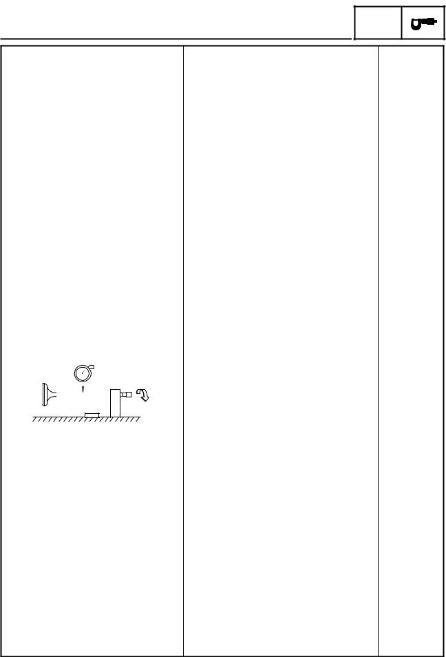
Valve springs |
|
|
Inner springs |
|
|
Free length |
|
|
Intake |
38.26 mm (1.51 in) |
36.26 mm |
|
|
(1.43 in) |
Exhaust |
38.26 mm (1.51 in) |
36.26 mm |
|
|
(1.43 in) |
Installed length (valve closed) |
|
|
Intake |
29.0 mm (1.14 in) |
---- |
Exhaust |
29.0 mm (1.14 in) |
---- |
Compressed spring force |
|
|
(installed) |
|
|
Intake |
63 ~ 73 N (6.3 ~ 7.3 kgf, 13.9~ 16.1 lb) |
---- |
Exhaust |
63 ~ 73 N (6.3 ~ 7.3 kgf, 13.9~ 16.1 lb) |
---- |
2 - 5
ENGINE SPECIFICATIONS SPEC
Item |
Standard |
Limit |
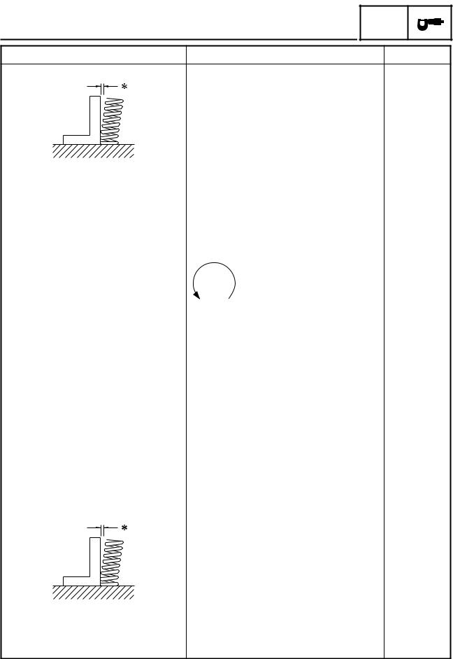
Spring tilt
Intake |
---- |
|
2.5˚ /2.4 mm |
|
|
|
|
|
|
(2.5˚/0.094 in) |
|
|
|
|
|
2 |
|
Exhaust |
---- |
|
2.5˚ /2.4 mm |
||
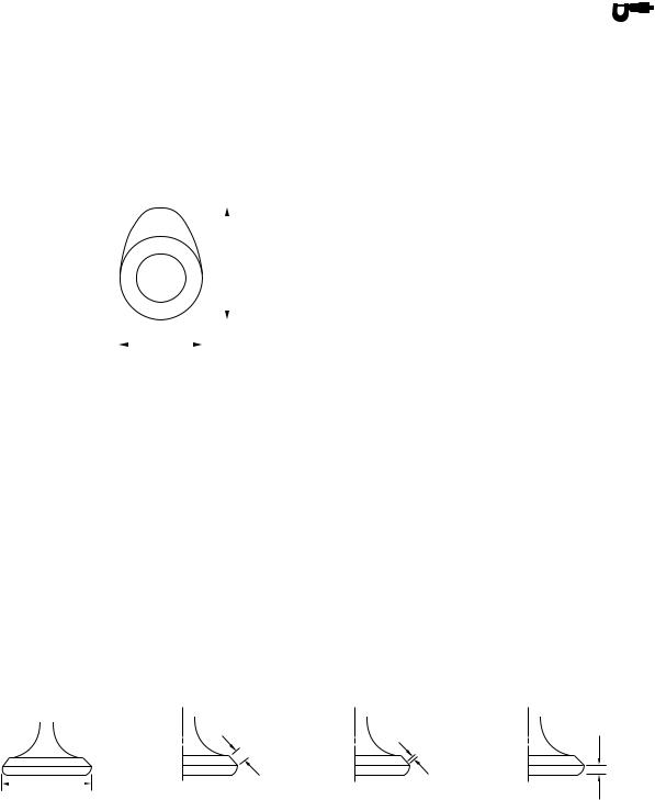
Winding direction (top view) |
|
|
|
(2.5˚/0.094 in) |
|
|
|
|
|
|
|
Intake |
Counterclockwise |
---- |
|
||
Exhaust |
Counterclockwise |
---- |
|
||
|
|
|
|
|
|
|
|
|
|
|
|
Outer springs |
|
|
Free length |
|
|
Intake |
43.25 mm (1.70 in) |
41.26 mm |
|
|
(1.62 in) |
Exhaust |
43.25 mm (1.70 in) |
41.26 mm |
|
|
(1.62 in) |
Installed length (valve closed) |
|
|
Intake |
31.0 mm (1.22 in) |
---- |
Exhaust |
31.0 mm (1.22 in) |
---- |
Compressed spring force |
|
|
(installed) |
|
|
Intake |
139 ~ 161 N |
---- |
|
(13.9 ~ 16.1 kgf, 30.6 ~ 35.5 lb) |
|
Exhaust |
139 ~ 161 N |
---- |
|
(13.9 ~ 16.1 kgf, 30.6 ~ 35.5 lb) |
|
Spring tilt |
|
|
Intake |
---- |
2.5˚ /2.4 mm |
|
|
(2.5˚/0.094 in) |
Exhaust |
---- |
2.5˚ /2.4 mm |
|
|
(2.5˚/0.094 in) |
2 - 6
|
|
|
|
|
|
|
|
|
|
|
ENGINE SPECIFICATIONS |
|
SPEC |
|
|
|
|
|
|
|
|
|
|
|
Item |
Standard |
|
Limit |
|
|
|
|
|
|
Winding direction (top view) |
|
|
|
|
Intake |
Clockwise |
---- |
||
Exhaust |
Clockwise |
---- |
||
|
|
Valve lifters |
|
|
||
|
|
Valve lifter outside diameter |
22.9680 ~ 22.9744 mm |
---- |
||
|
|
|
|
|
(0.9043 ~ 0.9045 in) |
|
2 |
|
|
|
|
|
|
|
Valve lifter case inside diameter |
22.990 ~ 23.010 mm |
---- |
|||
|
|
|
|
(0.9051 ~ 0.9059 in) |
|
|
|
|
Valve lifter-to-valve lifter case |
0.0156 ~ 0.0420 mm |
---- |
||
|
|
clearance |
(0.0006 ~ 0.0017 in) |
|
||
|
|
|
|
|
|
|
|
|
Valve push rods |
|
|
||
|
|
Valve push rod length |
293.45 ~ 293.95 mm |
---- |
||
|
|
|
|
|
(11.553 ~ 11.573 in) |
|
|
|
Valve push rod runout |
0.3 mm (0.012 in) |
---- |
||
|
|
|
|
|
|
|
|
|
Cylinders |
|
|
||
|
|
Bore |
95.000 ~ 95.010 mm |
---- |
||
|
|
|
|
|
(3.7402 ~ 3.7406 in) |
|
|
|
Max. taper |
---- |
0.05 mm |
||
|
|
|
|
|
|
(0.0016 in) |
|
|
Max. out of round |
---- |
0.05 mm |
||
|
|
|
|
|
|
(0.0016 in) |
|
|
|
|
|
|
|
|
|
Pistons |
|
|
||
|
|
Piston-to-cylinder clearance |
0.025 ~ 0.050 mm (0.001 ~ 0.002 in) |
0.15 mm |
||
|
|
|
|
|
|
(0.006 in) |
|
|
Diameter D |
94.960 ~ 94.975 mm |
---- |
||
|
|
|
|
|
(3.7386 ~ 3.7392 in) |
|
|
|
|
|
|
|
|
|
|
|
|
|
|
|
|
|
|
|
|
|
|
|
H |
|
D |
|
|
Height H |
5 mm (0.20 in) |
---- |
Piston pin bore (in the piston) |
|
|
Diameter |
22.004 ~ 22.015 mm |
22.045 mm |
|
(0.8663 ~ 0.8667 in) |
(0.8679 in) |
Offset |
1.0 mm (0.04 in) |
---- |
Piston pins |
|
|
Outside diameter |
21.991 ~ 22.000 mm |
21.971 mm |
|
(0.8658 ~ 0.8661 in) |
(0.8650 in) |
Piston pin-to-piston pin bore |
0.004 ~ 0.024 mm |
0.074 mm |
clearance |
(0.00016 ~ 0.00094 in) |
(0.0029 in) |
2 - 7
ENGINE SPECIFICATIONS SPEC
Item |
Standard |
Limit |
Piston rings
Top ring
|
|
|
|
|
|
|
|
|
|
|
|
|
|
|
|
|
|
|
|
|
|
|
|
|
|
|
|
|
|
|
B |
|
|
|
|
|
|
|
|
T |
|
|
|
|
|
|
|
|
|
|
|
||
|
|
|
|
|
|
|
|
||||||||||
|
|
|
|
|
|
|
|
|
|
|
|
|
|
|
|
|
|
Ring type |
|
|
|
|
|
|
|
|
|
|
Barrel |
---- |
|
|
|||
Dimensions (B × T) |
1.2 × 3.8 mm (0.047 × 0.150 in) |
---- |
|
|
|||||||||||||
End gap (installed) |
0.30 ~ 0.45 mm (0.012 ~ 0.018 in) |
0.65 mm |
|
|
|||||||||||||
|
|
|
|
|
|
|
|
|
|
|
|
|
|
|
(0.026 in) |
|
|
|
|
|
|
|
|
|
|
|
|
|
|
|
|
|
|
2 |
|
Ring side clearance |
0.03 ~ 0.08 mm (0.0012 ~ 0.0031 in) |
0.12 mm |
|
||||||||||||||
|
|
|
|
|
|
|
|
|
|
|
|
|
|
|
(0.0047 in) |
|
|
2nd ring |
|
|
|
|
|
|
|
|
|
|
|
|
|
||||
|
|
|
|
|
|
|
|
|
|
|
|
|
|
||||
|
|
|
|
|
|
|
|
|
|
|
|
|
B |
|
|
|
|
|
|
|
|
|
|
|
|
|
|
|
|
|
|
|
|
|
|
|
|
|
|
T |
|
|
|
|
|
|
|
|
|
|
|||
|
|
|
|
|
|
|
|
|
|
|
|
|
|
||||
|
|
|
|
|
|
|
|
|
|
|
|
|
|||||
|
|
|
|
|
|
|
|
|
|
|
|
|
|
|
|
|
|
Ring type |
|
|
|
|
|
|
|
|
|
|
Taper |
---- |
|
|
|||
Dimensions (B × T) |
1.2 × 3.8 mm (0.047 × 0.150 in) |
---- |
|
|
|||||||||||||
End gap (installed) |
0.30 ~ 0.45 mm (0.012 ~ 0.018 in) |
0.8 mm |
|
|
|||||||||||||
|
|
|
|
|
|
|
|
|
|
|
|
|
|
|
(0.031 in) |
|
|
Ring side clearance |
0.03 ~ 0.07 mm (0.0012 ~ 0.0028 in) |
0.12 mm |
|
|
|||||||||||||
|
|
|
|
|
|
|
|
|
|
|
|
|
|
|
(0.0047 in) |
|
|
Oil ring |
|
|
|
|
|
|
|
|
|
|
|
|
|
|
|||
|
|
|
|
|
|
|
|
|
|
|
|
|
|
|
|
|
|
|
|
|
|
|
|
|
|
|
|
|
B |
|
|
|
|
||
|
|
|
|
|
|
|
|
|
|
|
|
|
|
|
|||
|
|
|
|
|
|
|
|
|
|
|
|
|
|
|
|||
|
|
|
|
|
|
|
|
|
|
|
|
|
|
|
|||
|
|
|
|
T |
|
|
|
|
|
|
|
|
|
||||
|
|
|
|
|
|
|
|
|
|
|
|
|
|
|
|||
Dimensions (B × T) |
2.5 × 3.4 mm (0.098 × 0.134 in) |
---- |
|
|
|||||||||||||
End gap (installed) |
0.2 ~ 0.7 mm (0.008 ~ 0.028 in) |
---- |
|
|
|||||||||||||
|
|
|
|
|
|
|
|
|
|
|
|
|
|
|
|
|
|
Connecting rods |
|
|
|
|
|
|
|
|
|
|
|
|
|
|
|||
Crankshaft pin-to-big end bearing |
0.037 ~ 0.074 mm (0.0015 ~ 0.0029 in) |
---- |
|
|
|||||||||||||
clearance |
|
|
|
|
|
|
|
|
|
|
|
|
|
|
|||
Bearing color code |
|
|
|
|
|
|
|
|
|
|
1 = Blue, 2 = Black, 3 = Brown, |
---- |
|
|
|||
|
|
|
|
|
|
|
|
|
|
|
|
|
|
4 = Green, 5 = Yellow. |
|
|
|
Connecting rod length |
|
|
|
|
|
|
|
|
|
|
191.95 ~ 192.05 mm (7.557 ~ 7.561 in) |
|
|
|
|||
|
|
|
|
|
|
|
|
|
|
|
|
|
|
|
|
|
|
Crankshaft |
|
|
|
|
|
|
|
|
|
|
|
|
|
|
|||
C |
C |
|
|
|
|
||||||||||||
|
|
|
|
|
|
|
|
|
|
|
|
|
|
|
|
|
|
|
|
|
|
|
|
|
|
|
|
|
|
|
|
|
|
|
|
|
|
|
|
|
|
|
|
|
|
|
|
|
|
|
|
|
|
|
|
|
|
|
|
|
|
|
|
|
|
|
|
|
|
|
|
|
|
|
|
|
|
|
|
|
|
|
|
|
|
|
|
|
|
|
|
|
|
|
|
|
|
|
|
|
|
|
|
|
|
|
|
|
|
|
|
|
|
|
|
|
|
|
|
|
|
|
E |
|
|
|
|
|
|
|
|
|
|
|
|
|
|
|
|
|
|
|
|
|
|
|
|
|
|
|
|
|
|
|
|
|
|
|
|
|
|
|
|
|
|
|
|
|
|
|
|
|
|
|
|
|
|
|
D |
|
|
|
|
|
|
||||
|
|
|
|
|
|
|
|
|
|
|
|
|
||||||
|
|
|
|
|
|
|
|
|
|
|
|
|
|
|||||
|
|
|
|
|
|
|
A |
|
|
|
|
|
|
|
|
|
||
Width A |
132.8 ~ 133.2 mm (5.228 ~ 5.244 in) |
---- |
||||||||||||||||
Max. runout C |
|
0.04 mm |
||||||||||||||||
|
|
|
|
|
|
|
|
|
|
|
|
|
|
|
|
|
|
(0.0016 in) |
Big end side clearance D |
0.320 ~ 0.474 mm (0.013 ~ 0.019 in) |
---- |
||||||||||||||||
2 - 8

ENGINE SPECIFICATIONS SPEC
|
|
Item |
Standard |
Limit |
|
|
|
|
|
|
|
Big end radial clearance E |
0.037 ~ 0.074 mm (0.0015 ~ 0.0029 in) |
0.09 mm |
|
|
|
|
(0.0035 in) |
|
|
Crankshaft journal-to-crankshaft- |
0.030 ~ 0.062 mm (0.0012 ~ 0.0024 in) |
0.1 mm |
|
|
journal bearing clearance |
|
(0.0040 in) |
|
|
|
|
|
|
|
Clutch |
|
|
|
|
Clutch type |
Wet, multiple disc |
---- |
|
|
Clutch release method |
Rack and pinion (pull rod type) |
---- |
|
|
Clutch release method operation |
Cable operation |
---- |
|
|
Operation |
Left-hand operation |
---- |
|
|
|
|
|
2 |
|
Clutch cable free play (at the end |
10 ~ 15 mm (0.39 ~ 0.59 in) |
---- |
|
|
|||
|
|
of the clutch lever) |
|
|
|
|
Friction plates |
|
|
|
|
|
|
|
|
|
Thickness |
2.9 ~ 3.1 mm (0.114 ~ 0.122 in) |
2.8 mm |
|
|
|
|
(0.110 in) |
|
|
Plate quantity |
9 |
---- |
|
|
Clutch plates |
|
|
|
|
Thickness |
2.2 ~ 2.4 mm (0.087 ~ 0.094 in) |
---- |
|
|
Plate quantity |
8 |
---- |
|
|
Max. warpage |
---- |
0.2 mm |
|
|
|
|
(0.008 in) |
|
|
Clutch springs |
|
|
|
|
Free length |
7 mm (0.276 in) |
---- |
|
|
Spring quantity |
1 |
---- |
|
|
Min. length |
|
6.5 mm |
|
|
|
|
(0.256 in) |
|
|
|
|
|
|
|
Transmission |
|
|
|
|
Transmission type |
Constant mesh, 5-speed |
---- |
|
|
Primary reduction system |
Spur gear |
---- |
|
|
Primary reduction ratio |
72/47 (1.532) |
---- |
|
|
Secondary reduction system |
Belt drive |
---- |
|
|
Secondary reduction ratio |
35/32 × 70/33 (2.320) |
---- |
|
|
Operation |
Left-foot operation |
---- |
|
|
Gear ratios |
|
|
|
|
1st gear |
39/16 (2.437) |
---- |
|
|
2nd gear |
30/19 (1.578) |
---- |
|
|
3rd gear |
29/25 (1.160) |
---- |
|
|
4th gear |
29/32 (0.906) |
---- |
|
|
5th gear |
21/28 (0.750) |
---- |
|
|
Max. main axle runout |
---- |
0.08 mm |
|
|
|
|
(0.003 in) |
|
|
Max. drive axle runout |
---- |
0.08 mm |
|
|
|
|
(0.003 in) |
|
|
|
|
|
2 - 9

|
|
|
|
|
|
|
|
|
|
|
|
|
|
|
|
|
ENGINE SPECIFICATIONS |
|
SPEC |
|
|
|
|
|
|
|
|
|
|
|
|
|
|
|
|
|
|
|
|
Item |
Standard |
|
|
Limit |
|
|
|
|
|
|
|
|
|
|
|
Shifting mechanism |
|
|
|
|
|
|
|
Shift mechanism type |
Guide bar |
|
---- |
|
|
||
Max. shift fork guide bar bending |
---- |
|
|
0.025 mm |
|
|
|
|
|
|
|
(0.001 in) |
|
|
|
Shift fork thickness |
6.26 ~ 6.39 mm (0.246 ~ 0.252 in) |
|
---- |
|
|
||
|
|
|
|
|
|
||
Air filter type |
Dry element |
|
|
---- |
|
|
|
|
|
|
|
|
|
|
|
Fuel pump |
|
|
|
|
|
|
|
Pump type |
Electrical |
|
---- |
|
|
||
Model (manufacturer) |
4WM (MITSUBISHI) |
|
---- |
|
|
||
Output pressure |
15 ~ 20 kPa |
|
|
---- |
|
2 |
|
|
|
|
|||||
|
(0.15 ~0.20 kgf/cm2, 2.1 ~ 2.8 psi) |
|
|
|
|
|
|
Carburetor |
|
|
|
|
|
|
|
Model (manufacturer) × quantity |
BSR40 (MIKUNI) × 1 |
|
---- |
|
|
||
Throttle cable free play (at the |
3 ~ 5 mm (0.12 ~ 0.20 in) |
|
---- |
|
|
||
flange of the throttle grip) |
|
|
|
|
|
|
|
ID mark |
4WM1 00 |
|
---- |
|
|
||
|
4WM2 10 (for California) |
|
---- |
|
|
||
Main jet |
#165 |
|
---- |
|
|
||
Main air jet |
#60 |
|
---- |
|
|
||
Jet needle |
6HDC26 |
|
---- |
|
|
||
Needle jet |
X-2 |
|
---- |
|
|
||
Pilot air jet |
#100 |
|
---- |
|
|
||
Pilot outlet |
1.0 (XV16A), 1.1 (XV16AT) |
|
---- |
|
|
||
Pilot jet |
#35 |
|
---- |
|
|
||
Bypass 1 |
0.9 |
|
---- |
|
|
||
Bypass 2 |
1.0 |
|
---- |
|
|
||
Bypass 3 |
0.9 |
|
---- |
|
|
||
Pilot screw turns out |
2-1/2 |
|
---- |
|
|
||
Valve seat size |
2.0 |
|
---- |
|
|
||
Starter jet 1 |
#57.5 |
|
---- |
|
|
||
Starter jet 2 |
1.0 |
|
---- |
|
|
||
Butterfly valve size |
#110 |
|
---- |
|
|
||
Fuel level (below the float cham- |
2.0 ~ 3.0 mm (0.079 ~ 0.12 in) |
|
---- |
|
|
||
ber mating surface) |
|
|
|
|
|
|
|
|
|
|
|
|
|
|
|
2 - 10

|
|
|
|
|
|
|
|
|
|
|
|
|
|
|
|
|
|
|
|
|
CHASSIS SPECIFICATIONS |
|
SPEC |
|
||
|
|
|
|
|
|
|
|
|
|
|
CHASSIS SPECIFICATIONS |
|
|
|
|
|
|
|
|
|
|
|
|
|
|
|
|
|
|
|
|
|
|
||
|
|
Item |
|
Standard |
|
Limit |
||
|
|
|
|
|
|
|
|
|
|
|
Frame |
|
|
|
|
|
|
|
|
Frame type |
|
Double cradle |
|
---- |
||
|
|
Caster angle |
|
32˚ |
|
---- |
||
|
|
Trail |
|
142 mm (5.59 in) |
|
---- |
||
|
|
|
|
|
|
|
|
|
|
|
Front wheel |
|
|
|
|
|
|
|
|
Wheel type |
|
Spoke wheel |
|
---- |
||
|
|
Rim |
|
|
|
|
|
|
|
|
Size |
|
16 × MT3.00 |
|
---- |
||
2 |
|
|
|
|||||
|
Material |
|
Steel |
|
---- |
|||
|
Wheel travel |
|
140 mm (5.51 in) |
|
---- |
|||
|
|
Wheel runout |
|
|
|
|
|
|
|
|
Max. radial wheel runout |
|
---- |
|
|
1 mm |
|
|
|
|
|
|
|
|
(0.04 in) |
|
|
|
Max. lateral wheel runout |
|
---- |
|
|
0.5 mm |
|
|
|
|
|
|
|
|
(0.02 in) |
|
|
|
|
|
|
|
|
|
|
|
|
Rear wheel |
|
|
|
|
|
|
|
|
Wheel type |
|
Spoke wheel |
|
---- |
||
|
|
Rim |
|
|
|
|
|
|
|
|
Size |
|
16 × MT3.50 |
|
---- |
||
|
|
Material |
|
Steel |
|
---- |
||
|
|
Wheel travel |
|
110 mm (4.33 in) |
|
---- |
||
|
|
Wheel runout |
|
|
|
|
|
|
|
|
Max. radial wheel runout |
|
---- |
|
|
1 mm |
|
|
|
|
|
|
|
|
(0.04 in) |
|
|
|
Max. lateral wheel runout |
|
---- |
|
|
0.5 mm |
|
|
|
|
|
|
|
|
(0.02 in) |
|
|
|
|
|
|
|
|
|
|
|
|
Front tire |
|
|
|
|
|
|
|
|
Tire type |
|
With tube |
|
---- |
||
|
|
Size |
|
130/90 - 16 67H |
|
---- |
||
|
|
Model (manufacturer) |
|
D404FL (DUNLOP)/ |
|
---- |
||
|
|
|
|
G703F (BRIDGESTONE) |
|
|
|
|
|
|
Tire pressure (cold) |
|
|
|
|
|
|
|
|
0 ~ 90 kg (0 ~ 198 lb) |
|
250 kPa (2.5 kg/cm2, 36 psi) |
|
---- |
||
|
|
90 kg (198 lb) ~ Maximum load* |
|
250 kPa (2.5 kg/cm2, 36 psi) |
|
---- |
||
|
|
High-speed riding |
|
250 kPa (2.5 kg/cm2, 36 psi) |
|
---- |
||
|
|
|
|
* Load is the total weight of the cargo, |
|
|||
|
|
|
|
rider, passenger and accessories. |
|
|
|
|
|
|
Min. tire tread depth |
|
---- |
|
|
1.6 mm |
|
|
|
|
|
|
|
|
(0.06 in) |
|
|
|
|
|
|
|
|
|
|
2 - 11
 Loading...