

Page 1
Read this manual carefully before operating this vehicle.
OWNER’S MANUAL
XT250B
3C5-28199-24
Page 2

Q
Read this manual carefully before operating this vehicle. This manual should stay with this vehicle if it is sold.
EAU46090
Page 3
INTRODUCTION
EAU10102
Welcome to the Yamaha world of motorcycling!
As the owner of the XT250B, you are benefiting from Yamaha’s vast experience and newest technology regarding the design
and manufacture of high-quality products, which have earned Yamaha a reputation for dependability.
Please take the time to read this manual thoroughly, so as to enjoy all advantages of your XT250B. The Owner’s Manual
does not only instruct you in how to operate, inspect and maintain your motorcycle, but also in how to safeguard yourself and
others from trouble and injury.
In addition, the many tips given in this manual will help keep your motorcycle in the best possible condition. If you have any
further questions, do not hesitate to contact your Yamaha dealer.
The Yamaha team wishes you many safe and pleasant rides. So, remember to put safety first!
Yamaha continually seeks advancements in product design and quality. Therefore, while this manual contains the most current product information available at the time of printing, there may be minor discrepancies between your motorcycle and this
manual. If there is any question concerning this manual, please consult a Yamaha dealer.
WARNING
Please read this manual carefully and completely before operating this motorcycle.
EWA10031
Page 4
IMPORTANT MANUAL INFORMATION
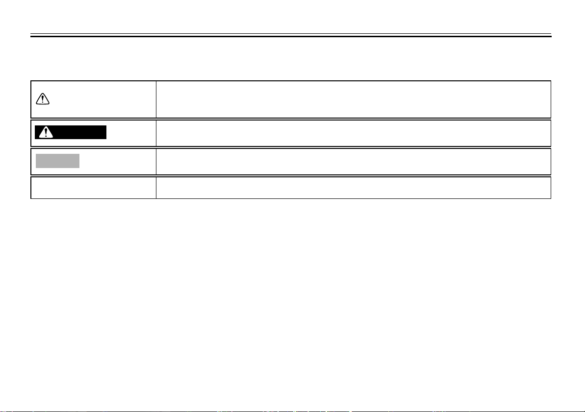
Particularly important information is distinguished in this manual by the following notations:
This is the safety alert symbol. It is used to alert you to potential personal injury
hazards. Obey all safety messages that follow this symbol to avoid possible injury
or death.
EAU10132
WARNING
NOTICE
TIP
A WARNING indicates a hazardous situation which, if not avoided, could result in
death or serious injury.
A NOTICE indicates special precautions that must be taken to avoid damage to the
vehicle or other property.
A TIP provides key information to make procedures easier or clearer.
Page 5
IMPORTANT MANUAL INFORMATION
XT250B
OWNER’S MANUAL
©2011 by Yamaha Motor Co., Ltd.
1st edition, April 2011
All rights reserved.
Any reprinting or unauthorized use
without the written permission of
Yamaha Motor Co., Ltd.
is expressly prohibited.
Printed in Japan.
EAU10200
Page 6
TABLE OF CONTENTS
LOCATION OF IMPORTANT
LABELS
SAFETY INFORMATION
DESCRIPTION
Left view ...........................................3-1
Right view .........................................3-2
Controls and instruments..................3-3
INSTRUMENT AND CONTROL
FUNCTIONS
Main switch/steering lock .................4-1
Indicator lights .................................4-2
Multi-function display .......................4-3
Handlebar switches .........................4-4
Clutch lever ......................................4-5
Shift pedal ........................................4-5
Brake lever ......................................4-6
Brake pedal .....................................4-6
Fuel tank cap ...................................4-6
Fuel ..................................................4-7
Fuel cock .........................................4-8
Starter (choke) knob .........................4-9
Seat ...............................................4-10
Helmet holder ................................4-10
Adjusting the shock absorber
Sidestand .......................................4-12
Ignition circuit cut-off system .........4-13
..............................................1-1
...................2-1
...................................3-1
........................................4-1
assembly ....................................4-11
FOR YOUR SAFETY –
PRE-OPERATION CHECKS
OPERATION AND IMPORTANT
RIDING POINTS
Starting and warming up a cold
engine .......................................... 6-1
Starting a warm engine ...................6-2
Shifting ............................................ 6-2
Tips for reducing fuel
consumption ................................ 6-3
Engine break-in ............................... 6-3
Parking ............................................ 6-4
PERIODIC MAINTENANCE AND
ADJUSTMENT
Owner’s tool kit ................................ 7-2
Periodic maintenance chart for
the emission control system ........ 7-3
General maintenance and
lubrication chart ........................... 7-4
Removing and installing the
cowling and panels ......................7-8
Checking the spark plug ................ 7-10
Engine oil and oil filter element .....7-12
Replacing the air filter element
and cleaning the check hose .....7-14
Adjusting the carburetor ................ 7-16
Adjusting the engine idling
speed ......................................... 7-16
.................................. 6-1
.................................... 7-1
.............. 5-1
Checking the throttle grip free
play ............................................ 7-17
Valve clearance ............................ 7-17
Tires .............................................. 7-17
Spoke wheels ............................... 7-19
Adjusting the clutch lever free
play ............................................ 7-20
Adjusting the brake lever free
play ............................................ 7-20
Brake light switches ...................... 7-21
Checking the front and rear
brake pads ................................. 7-21
Checking the brake fluid level ....... 7-22
Changing the brake fluid ............... 7-23
Drive chain slack ........................... 7-23
Cleaning and lubricating the
drive chain ................................. 7-25
Checking and lubricating the
cables ........................................ 7-25
Checking and lubricating the
throttle grip and cable ................ 7-26
Checking and lubricating the
brake and shift pedals ............... 7-26
Checking and lubricating the
brake and clutch levers .............. 7-27
Checking and lubricating the
sidestand ................................... 7-27
Lubricating the rear suspension .... 7-28
Checking the front fork .................. 7-28
Checking the steering ................... 7-29
Checking the wheel bearings ........ 7-29
Page 7
Battery ...........................................7-30
Replacing the fuse ......................... 7-31
Replacing the headlight bulb .........7-32
Replacing the tail/brake light
bulb ............................................7-33
Replacing a turn signal light
bulb ............................................7-34
Supporting the motorcycle ............. 7-34
Front wheel .................................... 7-35
Rear wheel ....................................7-36
Troubleshooting .............................7-38
Troubleshooting chart .................... 7-39
MOTORCYCLE CARE AND
STORAGE
Matte color caution ..........................8-1
Care .................................................8-1
Storage ............................................8-3
...........................................8-1
TABLE OF CONTENTS
SPECIFICATIONS
CONSUMER INFORMATION
Identification numbers ...................10-1
Motorcycle noise regulation
(for Australia) ..............................10-2
..............................9-1
............10-1
Page 8
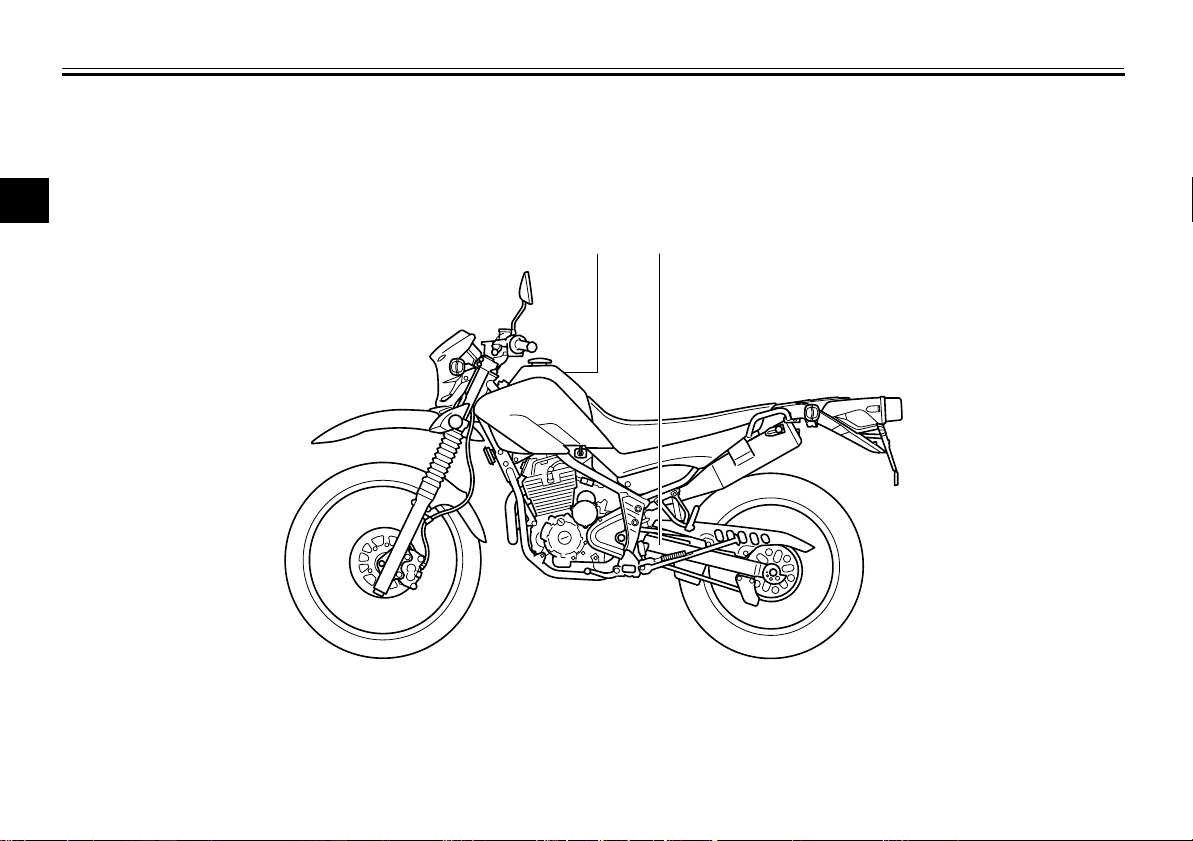
LOCATION OF IMPORTANT LABELS
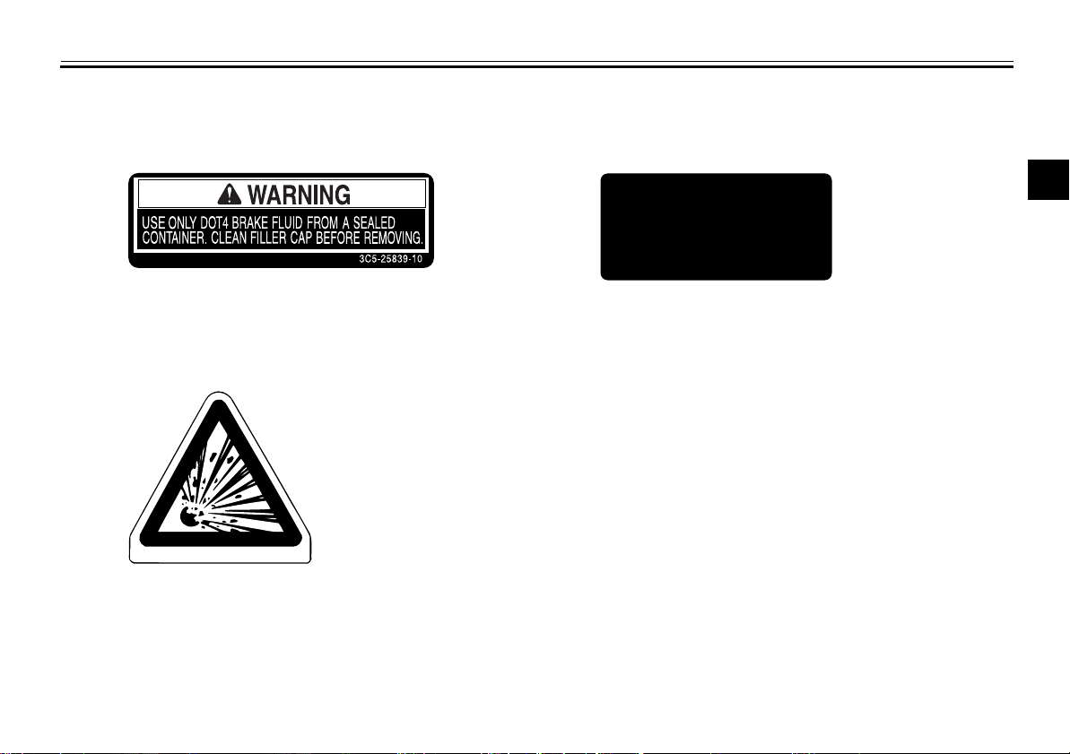
Read and understand all of the labels on your vehicle. They contain important information for safe and proper operation of
your vehicle. Never remove any labels from your vehicle. If a label becomes difficult to read or comes off, a replacement label
is available from your Yamaha dealer.
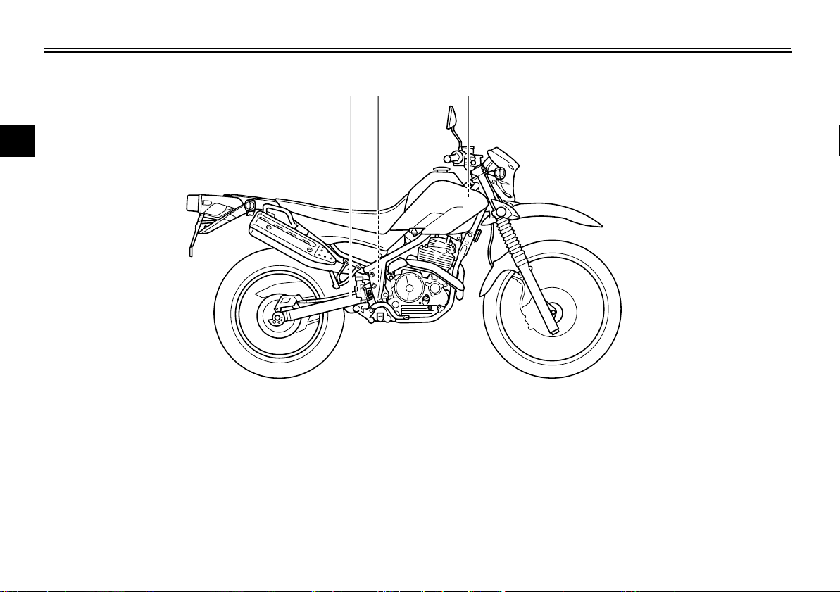
1
1 2
EAU10384
1-1
Page 9
LOCATION OF IMPORTANT LABELS
1
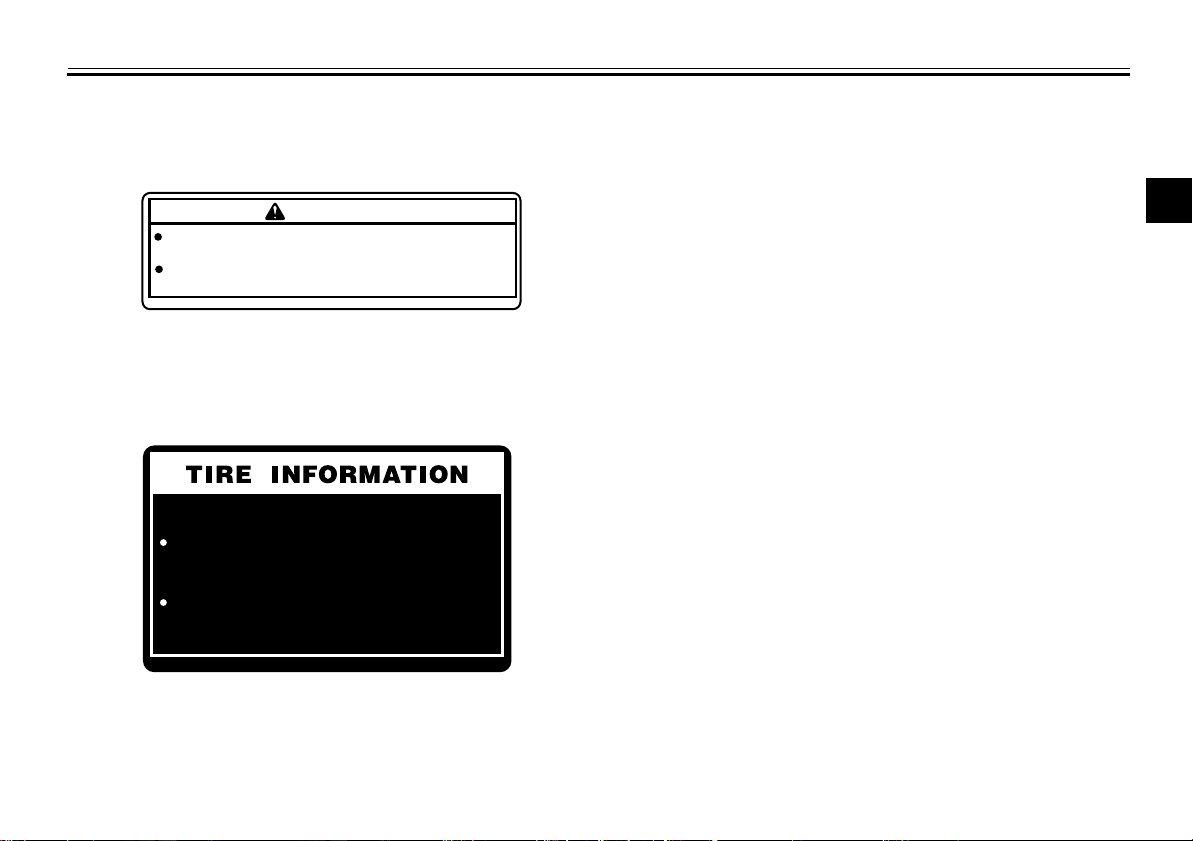
BEFORE YOU OPERATE THIS VEHICLE, READ
THE OWNER’S MANUAL AND ALL LABELS.
ALWAYS WEAR AN APPROVED MOTORCYCLE
HELMET, eye protection, and protective clothing.
WARNING
2
Cold tire normal pressure should be set
as follows.
Up to 90 kg (198Ibs) load
FRONT : 125 kPa, ( 1.25 kgf / cm2), 18 psi
REAR : 150 kPa, ( 1.50 kgf / cm2), 22 psi
90 kg (198 Ibs)~ maximum load
FRONT : 150 kPa, ( 1.50 kgf / cm
REAR : 175 kPa, ( 1.75 kgf / cm
5GK-2118K-00
2
), 22 psi
2
), 25 psi
3C5-21668-00
1
2
3
4
5
6
7
8
9
1-2
Page 10
LOCATION OF IMPORTANT LABELS
1
1
2
3
4
5
6
7
8
2
3
9
1-3
Page 11
LOCATION OF IMPORTANT LABELS
1
3
STATIONARY NOISE TEST INFORMATION
1
TESTED 80 dB(A) AT 3750 r/min
SILENCING SYSTEM : YAMAHA
2
IDENTIFICATION : 5XT
3C5-2118G-10
3
4
2
5
6
7
8
4AA-22259-40
9
1-4
Page 12
SAFETY INFORMATION
Be a Responsible Owner
As the vehicle’s owner, you are respon-
1
sible for the safe and proper operation
of your motorcycle.
2
Motorcycles are single-track vehicles.
Their safe use and operation are de-
3
pendent upon the use of proper riding
techniques as well as the expertise of
the operator. Every operator should
4
know the following requirements before
riding this motorcycle.
5
He or she should:
●
Obtain thorough instructions from
6
a competent source on all aspects
of motorcycle operation.
●
7
Observe the warnings and maintenance requirements in this Owner’s Manual.
8
●
Obtain qualified training in safe
and proper riding techniques.
●
9
Obtain professional technical service as indicated in this Owner’s
Manual and/or when made necessary by mechanical conditions.
EAU1031A
Safe Riding
Perform the pre-operation checks each
time you use the vehicle to make sure it
is in safe operating condition. Failure to
inspect or maintain the vehicle properly
increases the possibility of an accident
or equipment damage. See page 5-1
for a list of pre-operation checks.
●
This motorcycle is designed to carry the operator and a passenger.
●
The failure of motorists to detect
and recognize motorcycles in traffic is the predominating cause of
automobile/motorcycle accidents.
Many accidents have been caused
by an automobile driver who did
not see the motorcycle. Making
yourself conspicuous appears to
be very effective in reducing the
chance of this type of accident.
Therefore:
• Wear a brightly colored jacket.
• Use extra caution when you are
approaching and passing
through intersections, since intersections are the most likely
places for motorcycle accidents
to occur.
• Ride where other motorists can
see you. Avoid riding in another
motorist’s blind spot.
●
Many accidents involve inexperienced operators. In fact, many operators who have been involved in
accidents do not even have a current motorcycle license.
• Make sure that you are qualified
and that you only lend your motorcycle to other qualified operators.
• Know your skills and limits.
Staying within your limits may
help you to avoid an accident.
• We recommend that you practice riding your motorcycle
where there is no traffic until you
have become thoroughly familiar with the motorcycle and all of
its controls.
●
Many accidents have been caused
by error of the motorcycle operator. A typical error made by the operator is veering wide on a turn
due to excessive speed or undercornering (insufficient lean angle
for the speed).
2-1
Page 13
SAFETY INFORMATION
• Always obey the speed limit and
never travel faster than warranted by road and traffic conditions.
• Always signal before turning or
changing lanes. Make sure that
other motorists can see you.
●
The posture of the operator and
passenger is important for proper
control.
• The operator should keep both
hands on the handlebar and
both feet on the operator footrests during operation to maintain control of the motorcycle.
• The passenger should always
hold onto the operator, the seat
strap or grab bar, if equipped,
with both hands and keep both
feet on the passenger footrests.
Never carry a passenger unless
he or she can firmly place both
feet on the passenger footrests.
●
Never ride under the influence of
alcohol or other drugs.
Protective Apparel
The majority of fatalities from motorcycle accidents are the result of head in-
juries. The use of a safety helmet is the
single most critical factor in the prevention or reduction of head injuries.
●
Always wear an approved helmet.
●
Wear a face shield or goggles.
Wind in your unprotected eyes
could contribute to an impairment
of vision that could delay seeing a
hazard.
●
The use of a jacket, heavy boots,
trousers, gloves, etc., is effective in
preventing or reducing abrasions
or lacerations.
●
Never wear loose-fitting clothes,
otherwise they could catch on the
control levers, footrests, or wheels
and cause injury or an accident.
●
Always wear protective clothing
that covers your legs, ankles, and
feet. The engine or exhaust system become very hot during or after operation and can cause burns.
●
A passenger should also observe
the above precautions.
Avoid Carbon Monoxide Poisoning
All engine exhaust contains carbon
monoxide, a deadly gas. Breathing car-
bon monoxide can cause headaches,
dizziness, drowsiness, nausea, confusion, and eventually death.
Carbon Monoxide is a colorless, odorless, tasteless gas which may be
present even if you do not see or smell
any engine exhaust. Deadly levels of
carbon monoxide can collect rapidly
and you can quickly be overcome and
unable to save yourself. Also, deadly
levels of carbon monoxide can linger
for hours or days in enclosed or poorly
ventilated areas. If you experience any
symptoms of carbon monoxide poisoning, leave the area immediately, get
fresh air, and SEEK MEDICAL TREATMENT.
●
Do not run engine indoors. Even if
you try to ventilate engine exhaust
with fans or open windows and
doors, carbon monoxide can rapidly reach dangerous levels.
●
Do not run engine in poorly ventilated or partially enclosed areas
such as barns, garages, or carports.
●
Do not run engine outdoors where
engine exhaust can be drawn into
2
3
4
5
6
7
8
9
2-2
Page 14
SAFETY INFORMATION
a building through openings such
as windows and doors.
Loading
1
Adding accessories or cargo to your
motorcycle can adversely affect stability and handling if the weight distribution
2
of the motorcycle is changed. To avoid
the possibility of an accident, use ex-
3
treme caution when adding cargo or
accessories to your motorcycle. Use
extra care when riding a motorcycle
4
that has added cargo or accessories.
Here, along with the information about
5
accessories below, are some general
guidelines to follow if loading cargo to
6
your motorcycle:
The total weight of the operator, passenger, accessories and cargo must
7
not exceed the maximum load limit.
Operation of an overloaded vehicle
8
could cause an accident.
9
Maximum load:
151 kg (333 lb)
When loading within this weight limit,
keep the following in mind:
●
Cargo and accessory weight
should be kept as low and close to
the motorcycle as possible. Securely pack your heaviest items as
close to the center of the vehicle as
possible and make sure to distribute the weight as evenly as possible on both sides of the motorcycle
to minimize imbalance or instability.
●
Shifting weights can create a sudden imbalance. Make sure that accessories and cargo are securely
attached to the motorcycle before
riding. Check accessory mounts
and cargo restraints frequently.
• Properly adjust the suspension
for your load (suspension-adjustable models only), and
check the condition and pressure of your tires.
• Never attach any large or heavy
items to the handlebar, front
fork, or front fender. These
items, including such cargo as
sleeping bags, duffel bags, or
tents, can create unstable handling or a slow steering response.
●
This vehicle is not designed to
pull a trailer or to be attached to
a sidecar.
Genuine Yamaha Accessories
Choosing accessories for your vehicle
is an important decision. Genuine
Yamaha accessories, which are available only from a Yamaha dealer, have
been designed, tested, and approved
by Yamaha for use on your vehicle.
Many companies with no connection to
Yamaha manufacture parts and accessories or offer other modifications for
Yamaha vehicles. Yamaha is not in a
position to test the products that these
aftermarket companies produce.
Therefore, Yamaha can neither endorse nor recommend the use of accessories not sold by Yamaha or
modifications not specifically recommended by Yamaha, even if sold and
installed by a Yamaha dealer.
Aftermarket Parts, Accessories,
and Modifications
While you may find aftermarket products similar in design and quality to
2-3
Page 15
SAFETY INFORMATION
genuine Yamaha accessories, recognize that some aftermarket accessories
or modifications are not suitable because of potential safety hazards to you
or others. Installing aftermarket products or having other modifications performed to your vehicle that change any
of the vehicle’s design or operation
characteristics can put you and others
at greater risk of serious injury or death.
You are responsible for injuries related
to changes in the vehicle.
Keep the following guidelines in mind,
as well as those provided under “Loading” when mounting accessories.
●
Never install accessories or carry
cargo that would impair the performance of your motorcycle. Carefully inspect the accessory before
using it to make sure that it does
not in any way reduce ground
clearance or cornering clearance,
limit suspension travel, steering
travel or control operation, or obscure lights or reflectors.
• Accessories fitted to the handlebar or the front fork area can
create instability due to improper
weight distribution or aerodynamic changes. If accessories
are added to the handlebar or
front fork area, they must be as
lightweight as possible and
should be kept to a minimum.
• Bulky or large accessories may
seriously affect the stability of
the motorcycle due to aerodynamic effects. Wind may attempt to lift the motorcycle, or
the motorcycle may become unstable in cross winds. These accessories may also cause
instability when passing or being
passed by large vehicles.
• Certain accessories can displace the operator from his or
her normal riding position. This
improper position limits the freedom of movement of the operator and may limit control ability,
therefore, such accessories are
not recommended.
●
Use caution when adding electrical accessories. If electrical accessories exceed the capacity of the
motorcycle’s electrical system, an
electric failure could result, which
could cause a dangerous loss of
lights or engine power.
Aftermarket Tires and Rims
The tires and rims that came with your
motorcycle were designed to match the
performance capabilities and to provide
the best combination of handling, braking, and comfort. Other tires, rims, sizes, and combinations may not be
appropriate. Refer to page 7-17 for tire
specifications and more information on
replacing your tires.
Transporting the Motorcycle
Be sure to observe following instructions before transporting the motorcycle in another vehicle.
●
Remove all loose items from the
motorcycle.
●
Check that the fuel cock (if
equipped) is in the “OFF” position
and that there are no fuel leaks.
●
Point the front wheel straight
ahead on the trailer or in the truck
bed, and choke it in a rail to prevent movement.
2
3
4
5
6
7
8
9
2-4
Page 16
SAFETY INFORMATION
●
Shift the transmission in gear (for
models with a manual transmission).
●
Secure the motorcycle with
1
2
3
4
5
6
7
8
tie-downs or suitable straps that
are attached to solid parts of the
motorcycle, such as the frame or
upper front fork triple clamp (and
not, for example, to rubber-mounted handlebars or turn signals, or
parts that could break). Choose
the location for the straps carefully
so the straps will not rub against
painted surfaces during transport.
●
The suspension should be compressed somewhat by the
tie-downs, if possible, so that the
motorcycle will not bounce excessively during transport.
9
2-5
Page 17
Left view
DESCRIPTION
EAU10410
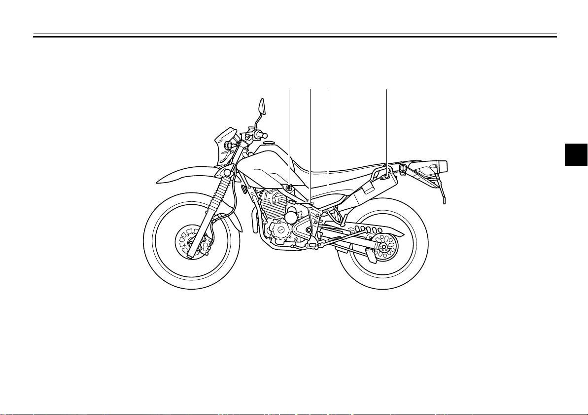
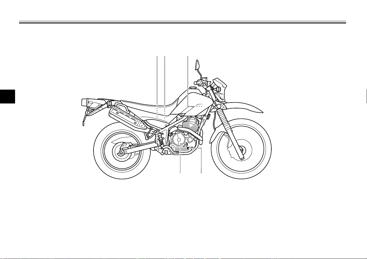
1 2 43
2
3
4
5
6
7
1. Fuel cock (page 4-8)
2. Starter (choke) knob (page 4-9)
3. Air filter element (page 7-14)
4. Helmet holder (page 4-10)
8
9
3-1
Page 18
DESCRIPTION
Right view
1
2
3
4
5
6
7
EAU10420
12 3
8
1. Battery (page 7-30)
2. Fuse (page 7-31)
9
3. Owner’s tool kit (page 7-2)
4. Engine oil level check window (page 7-12)
5. Engine oil filler bolt (page 7-12)
5
3-2
4
Page 19
Controls and instruments
DESCRIPTION
EAU10430
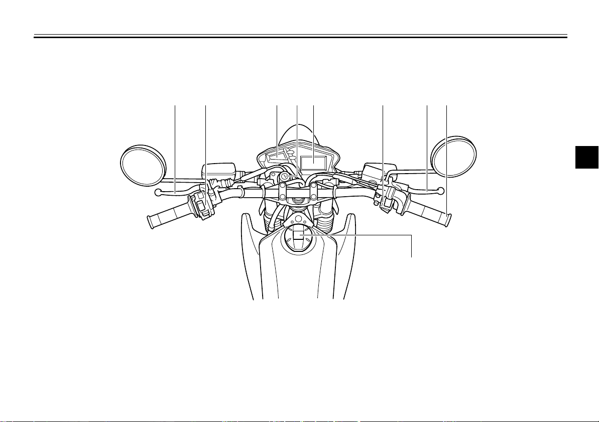
1. Clutch lever (page 4-5)
2. Left handlebar switches (page 4-4)
3. Indicator lights (page 4-2)
4. Main switch/steering lock (page 4-1)
5. Multi-function display (page 4-3)
6. Right handlebar switches (page 4-4)
7. Brake lever (page 4-6)
12 6 83 5 7
4
9
8. Throttle grip (page 7-17)
9. Fuel tank cap (page 4-6)
2
3
4
5
6
7
8
9
3-3
Page 20

INSTRUMENT AND CONTROL FUNCTIONS
1
2
Main switch/steering lock
1
2
3
4
The main switch/steering lock controls
the ignition and lighting systems, and is
5
used to lock the steering. The various
positions are described below.
6
ON
7
All electrical circuits are supplied with
power, and the meter lighting and taillight come on, and the engine can be
8
started. The key cannot be removed.
TIP
9
The headlight comes on automatically
when the engine is started and stays on
until the key is turned to “OFF”, even if
the engine stalls.
EAU10460
EAU45110
EAU10661
OFF
All electrical systems are off. The key
can be removed.
EWA10061
WARNING
Never turn the key to “OFF” or
“LOCK” while the vehicle is moving.
Otherwise the electrical systems will
be switched off, which may result in
loss of control or an accident.
EAU10691
LOCK
The steering is locked, and all electrical
systems are off. The key can be removed.
To lock the steering
1. Push.
2. Turn.
1. Turn the handlebars all the way to
the left or right.
2. Push the key in from the “OFF” position, and then turn it to “LOCK”
while still pushing it.
3. Remove the key.
4-1
Page 21
INSTRUMENT AND CONTROL FUNCTIONS
To unlock the steering
1
2
1. Push.
2. Turn.
Push the key into the main switch, and
then turn it to “OFF” while still pushing
it.
EAU10981
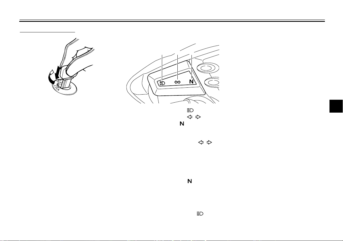
Indicator lights
1 2
1. High beam indicator light “”
2. Turn signal indicator light “”
3. Neutral indicator light “”
Turn signal indicator light “”
This indicator light flashes when the
turn signal switch is pushed to the left or
right.
Neutral indicator light “”
This indicator light comes on when the
transmission is in the neutral position.
3
EAU11020
EAU11060
high beam of the headlight is switched
on.
2
3
4
5
6
7
8
9
EAU11080
High beam indicator light “”
This indicator light comes on when the
4-2
Page 22
INSTRUMENT AND CONTROL FUNCTIONS
Multi-function display
WARNING
Be sure to stop the vehicle before
1
making any setting changes to the
multi-function display. Changing
2
settings while riding can distract the
operator and increase the risk of an
3
accident.
1
4
5
6
7
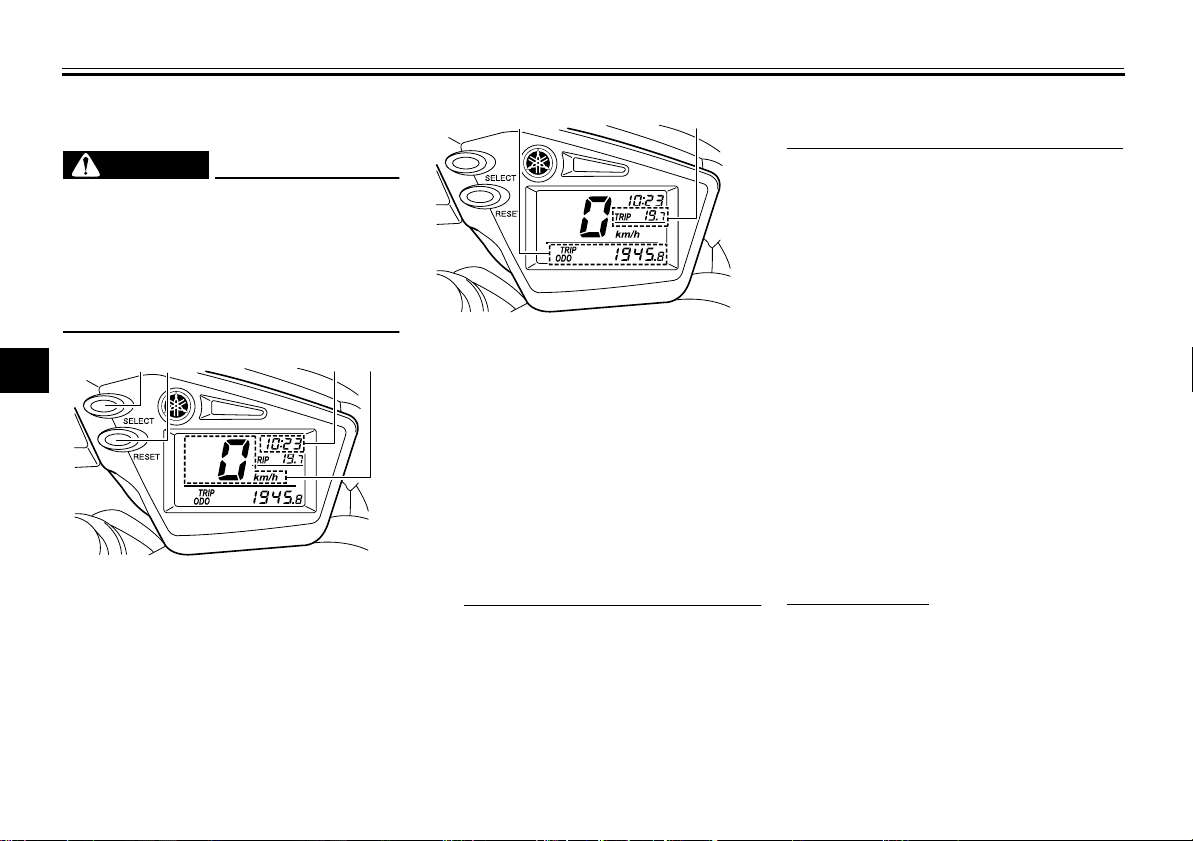
1. “SELECT” button
8
2. “RESET” button
3. Clock
9
4. Speedometer
2
3
EAU44873
EWA12312
4
1
1. Odometer/tripmeter (bottom)
2. Tripmeter (top)
2
The multi-function display is equipped
with the following:
●
a speedometer
●
an odometer
●
two tripmeters (which show the
distance traveled since they were
last set to zero)
●
a clock
TIP
Be sure to turn the key to “ON” be-
●
fore using the “SELECT” and
“RESET” buttons.
When the key is turned to “ON”, all
●
of the display segments of the
multi-function display will appear
one after the other and then disap-
pear, in order to test the electrical
circuit.
Odometer, clock and tripmeter
modes
Pushing the “SELECT” button switches
the display between the odometer
mode “ODO” and the tripmeter modes
“TRIP” in the following order:
ODO → TRIP (top) → TRIP (bottom)
→
ODO
To reset a tripmeter, select it by pushing the “SELECT” button until “TRIP”
begins flashing (“TRIP” will only flash
for five seconds). While “TRIP” is flashing, push the “RESET” button for at
least one second.
Clock mode
To set the clock:
1. Push the “SELECT” button and
“RESET” button together for at
least two seconds.
2. When the hour digits start flashing,
push the “RESET” button to set the
hours.
3. Push the “SELECT” button, and
4-3
Page 23
INSTRUMENT AND CONTROL FUNCTIONS
1
2
the minute digits will start flash-
ing.
4. Push the “RESET” button to set
the minutes.
5. Push the “SELECT” button and
then release it to start the clock.
Handlebar switches
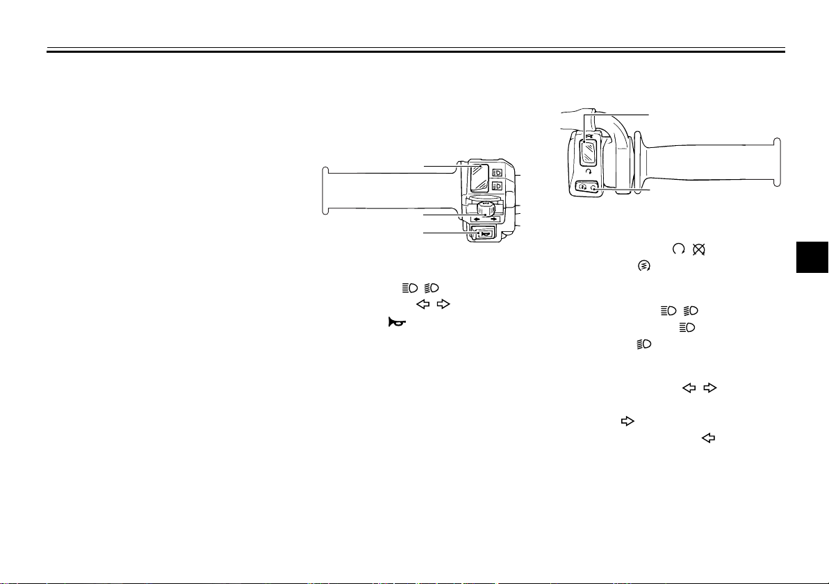
Left
1
2
3
1. Dimmer switch “ / ”
2. Turn signal switch “ / ”
3. Horn switch “”
EAU12348
Right
1. Engine stop switch “ / ”
2. Start switch “”
EAU12400
Dimmer switch “ / ”
Set this switch to “” for the high
beam and to “” for the low beam.
EAU12460
Turn signal switch “ / ”
To signal a right-hand turn, push this
switch to “”. To signal a left-hand
turn, push this switch to “”. When re-
leased, the switch returns to the center
position. To cancel the turn signal
lights, push the switch in after it has returned to the center position.
2
3
4
5
6
7
8
9
4-4
Page 24
INSTRUMENT AND CONTROL FUNCTIONS
1
Horn switch “”
Press this switch to sound the horn.
1
Engine stop switch “ / ”
Set this switch to “” before starting
the engine. Set this switch to “” to
2
stop the engine in case of an emergency, such as when the vehicle overturns
3
or when the throttle cable is stuck.
4
Start switch “”
Push this switch to crank the engine
5
with the starter. See page 6-1 for starting instructions prior to starting the en-
6
gine.
7
8
9
EAU12500
EAU12660
EAU12711
EAU12820
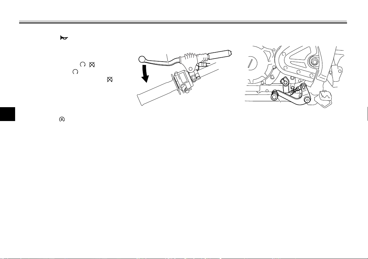
Clutch lever
1
1. Clutch lever
The clutch lever is located at the left
handlebar grip. To disengage the
clutch, pull the lever toward the handlebar grip. To engage the clutch, release
the lever. The lever should be pulled
rapidly and released slowly for smooth
clutch operation.
The clutch lever is equipped with a
clutch switch, which is part of the ignition circuit cut-off system. (See
page 4-13.)
EAU12871
Shift pedal
1. Shift pedal
The shift pedal is located on the left
side of the motorcycle and is used in
combination with the clutch lever when
shifting the gears of the 5-speed constant-mesh transmission equipped on
this motorcycle.
4-5
Page 25
INSTRUMENT AND CONTROL FUNCTIONS
1
2
EAU12890
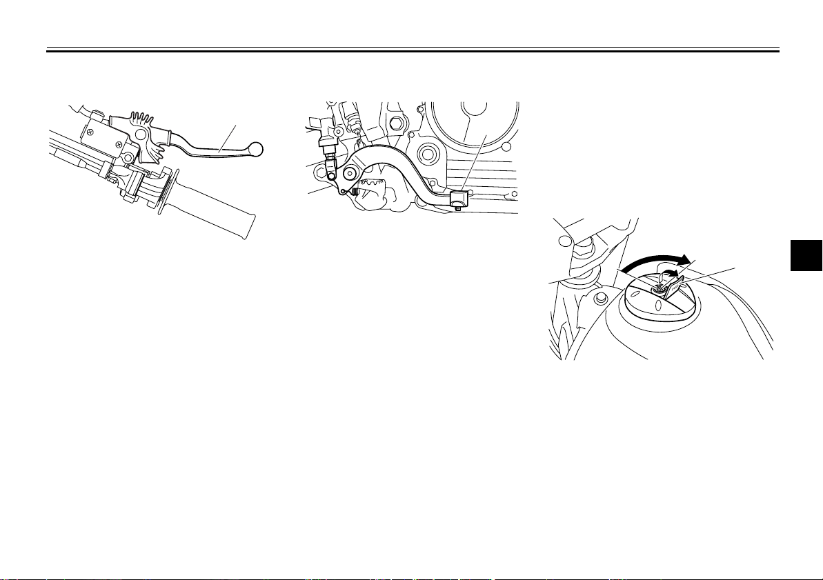
Brake lever
1
1. Brake lever
The brake lever is located at the right
handlebar grip. To apply the front
brake, pull the lever toward the handlebar grip.
EAU12941
Brake pedal
1
1. Brake pedal
The brake pedal is on the right side of
the motorcycle. To apply the rear
brake, press down on the brake pedal.
Fuel tank cap
To remove the fuel tank cap
1. Open the fuel tank cap lock cover.
2. Insert the key into the lock and turn
it 1/4 turn clockwise. The lock will
be released and the fuel tank cap
can be removed.
1. Fuel tank cap lock cover
2. Unlock.
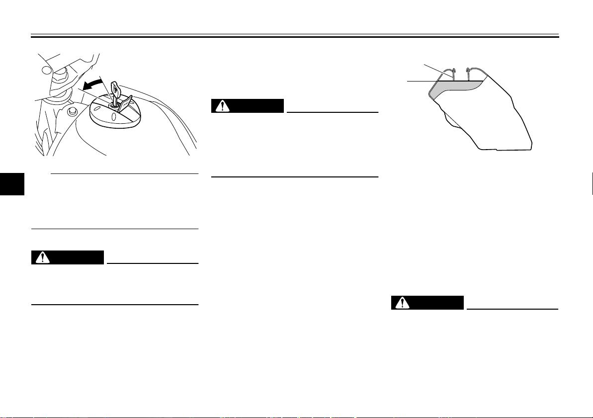
To install the fuel tank cap
1. Push and install the fuel tank cap
into position with the key inserted
in the lock.
2. Turn the key counterclockwise to
the original position, and then remove it.
EAUM1793
2
3
4
5
6
7
8
9
4-6
Page 26
INSTRUMENT AND CONTROL FUNCTIONS
1
2
Fuel
Make sure there is sufficient gasoline in
the tank.
1
2
3
TIP
The fuel tank cap cannot be installed
4
unless the key is in the lock. In addition,
the key cannot be removed if the cap is
5
not properly installed and locked.
3. Close the lock cover.
6
WARNING
7
Make sure that the fuel tank cap is
properly installed before riding.
Leaking fuel is a fire hazard.
8
9
EWA11141
WARNING
Gasoline and gasoline vapors are
extremely flammable. To avoid fires
and explosions and to reduce the
risk of injury when refueling, follow
these instructions.
1. Before refueling, turn off the engine and be sure that no one is sitting on the vehicle. Never refuel
while smoking, or while in the vicinity of sparks, open flames, or
other sources of ignition such as
the pilot lights of water heaters and
clothes dryers.
2. Do not overfill the fuel tank. Stop
filling when the fuel reaches the
bottom of the filler tube. Because
fuel expands when it heats up,
heat from the engine or the sun
can cause fuel to spill out of the
fuel tank.
EAU13212
EWA10881
1. Maximum fuel level
2. Fuel tank filler tube
3. Wipe up any spilled fuel immediately.
NOTICE:
Immediately wipe
off spilled fuel with a clean, dry,
soft cloth, since fuel may deteriorate painted surfaces or plastic
parts.
[ECA10071]
4. Be sure to securely close the fuel
tank cap.
EWA15151
WARNING
Gasoline is poisonous and can
cause injury or death. Handle gasoline with care. Never siphon gasoline by mouth. If you should swallow
some gasoline or inhale a lot of gasoline vapor, or get some gasoline in
4-7
Page 27
INSTRUMENT AND CONTROL FUNCTIONS
1
your eyes, see your doctor immediately. If gasoline spills on your skin,
wash with soap and water. If gasoline spills on your clothing, change
your clothes.
EAU13321
Recommended fuel:
Unleaded gasoline only
Fuel tank capacity:
10.0 L (2.64 US gal, 2.20 Imp.gal)
Fuel reserve amount:
1.9 L (0.50 US gal, 0.42 Imp.gal)
ECA11400
NOTICE
Use only unleaded gasoline. The use
of leaded gasoline will cause severe
damage to internal engine parts,
such as the valves and piston rings,
as well as to the exhaust system.
Your Yamaha engine has been designed to use regular unleaded gasoline with a research octane number of
91 or higher. If knocking (or pinging) occurs, use a gasoline of a different brand
or premium unleaded fuel. Use of un-
leaded fuel will extend spark plug life
and reduce maintenance costs.
EAU13561
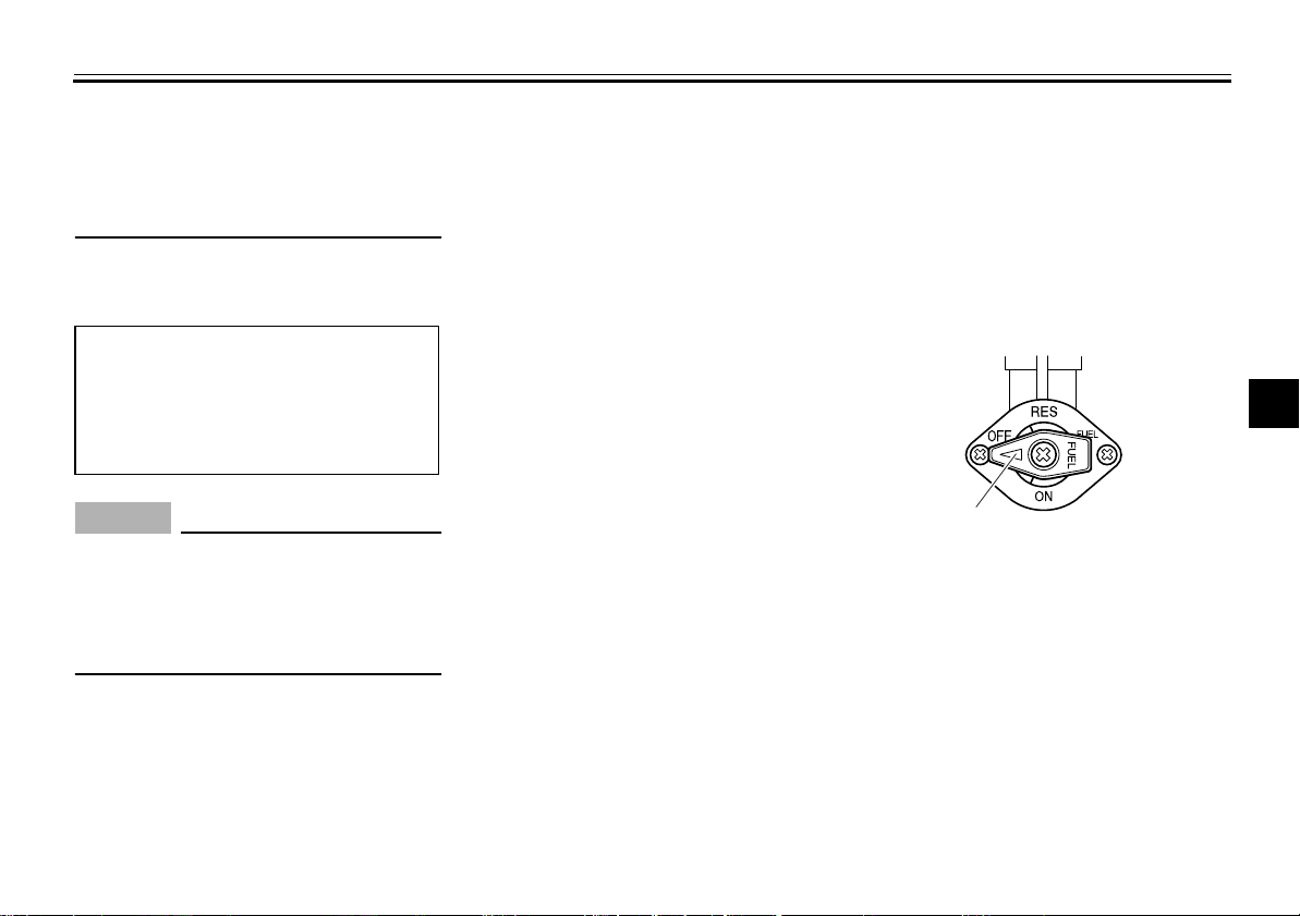
Fuel cock
The fuel cock supplies fuel from the
tank to the carburetor while filtering it also.
The fuel cock has three positions:
OFF
1. Pointed end positioned under “OFF”
With the lever in this position, fuel will
not flow. Always return the lever to this
position when the engine is not running.
2
3
4
5
6
7
8
9
4-8
Page 28
INSTRUMENT AND CONTROL FUNCTIONS
1
(a)
(b)
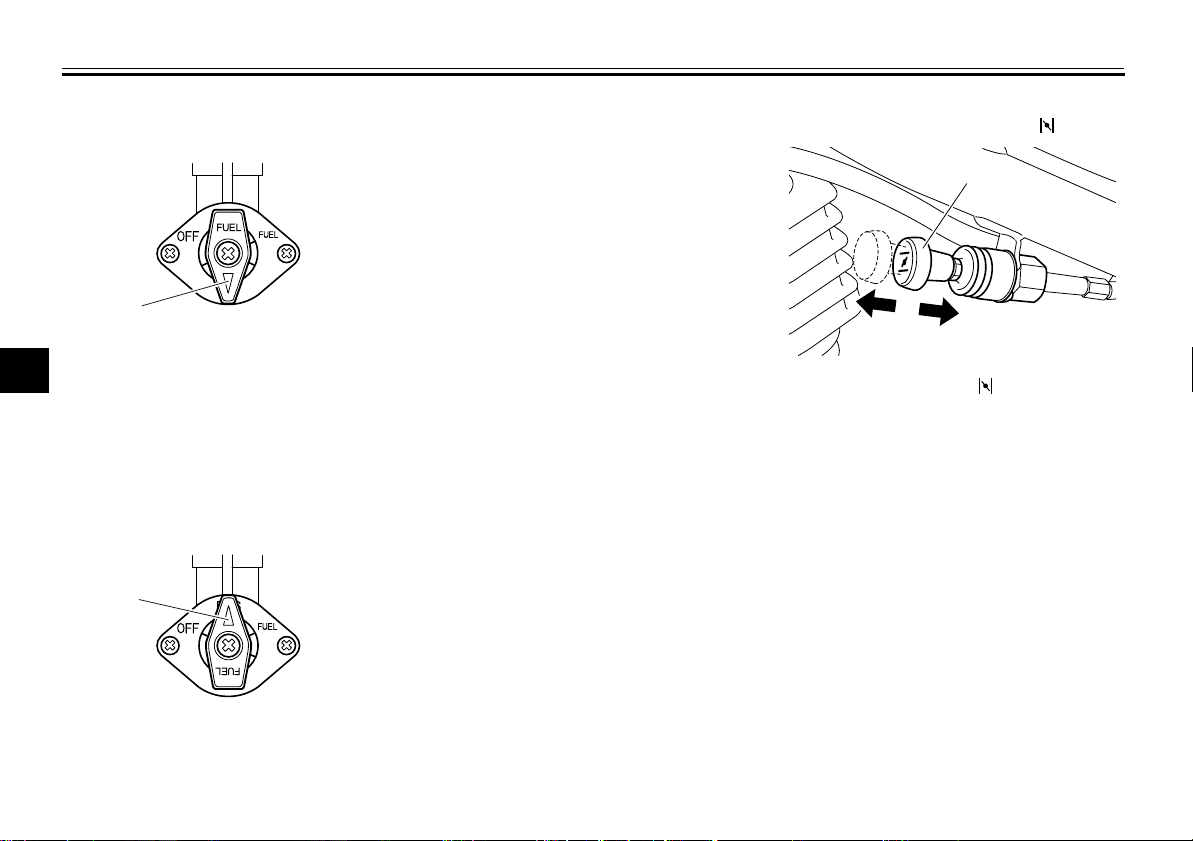
ON
1
2
3
4
With the lever in this position, fuel flows
to the carburetor. Normal riding is done
5
with the lever in this position.
6
RES
7
8
9
1
1. Pointed end positioned over “ON”
1
This indicates reserve. If you run out of
fuel while riding, move the lever to this
position. Fill the tank at the first opportunity. Be sure to set the lever back to
“ON” after refueling!
EAU13600
Starter (choke) knob “”
1. Starter (choke) knob “”
Starting a cold engine requires a richer
air-fuel mixture, which is supplied by
the starter (choke).
Move the knob in direction (a) to turn on
the starter (choke).
Move the knob in direction (b) to turn off
the starter (choke).
1. Pointed end positioned over “RES”
4-9
Page 29
INSTRUMENT AND CONTROL FUNCTIONS
1
2
EAU13971
Seat
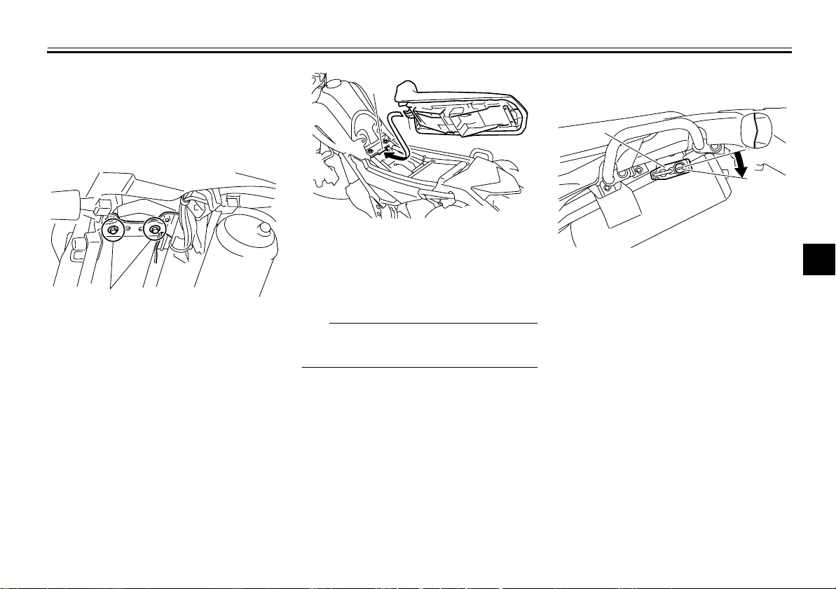
To remove the seat
Remove the bolts, and then pull the
seat off.
1
1. Bolt
To install the seat
1. Insert the projection on the front of
the seat into the seat holder as
shown.
1
2
1. Seat holder
2. Projection
2. Place the seat in the original position, and then tighten the bolts.
TIP
Make sure that the seat is properly secured before riding.
EAU14282
Helmet holder
1. Helmet holder
2. Unlock.
To open the helmet holder, insert the
key into the lock, and then turn the key
as shown.
To lock the helmet holder, place it in the
original position, and then remove the
key.
WARNING! Never ride with a
helmet attached to the helmet holder, since the helmet may hit objects,
causing loss of control and possibly
an accident.
[EWA10161]
2
3
4
5
6
7
8
9
4-10
Page 30
INSTRUMENT AND CONTROL FUNCTIONS
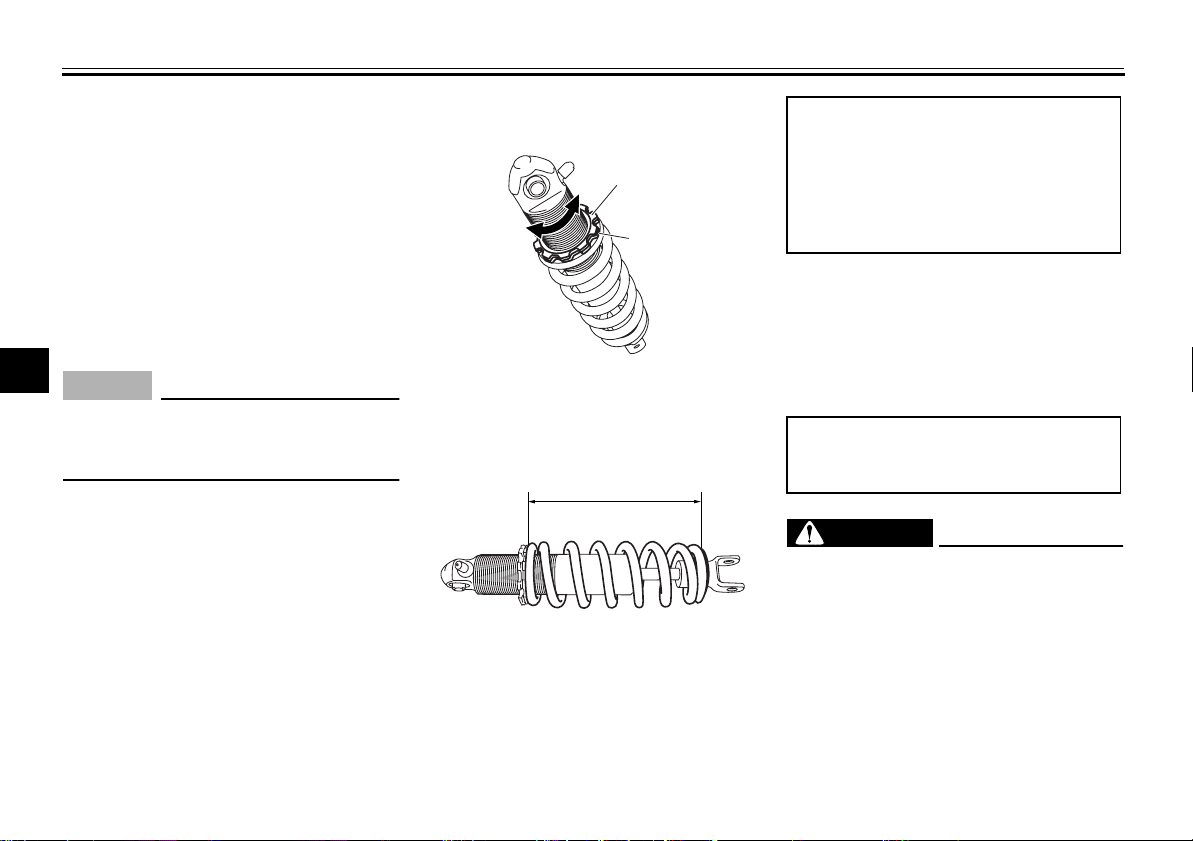
Adjusting the shock absorber assembly
This shock absorber assembly is
1
equipped with a spring preload adjusting ring.
It is recommended to have a Yamaha
2
dealer adjust the spring preload. However, if you choose to make this adjust-
3
ment yourself, obtain a special wrench
at a Yamaha dealer.
4
NOTICE
To avoid damaging the mechanism,
5
do not attempt to turn beyond the
maximum or minimum settings.
6
1. Loosen the locknut.
2. To increase the spring preload and
7
8
9
thereby harden the suspension,
turn the spring preload adjusting
ring in direction (a). To decrease
the spring preload and thereby
soften the suspension, turn the adjusting ring in direction (b).
The spring preload setting is determined by measuring distance A,
shown in the illustration. The shorter the distance A is, the higher the
EAU44773
ECA10101
spring preload; the longer distance
A is, the lower the spring preload.
1
(b)
(a)
1. Locknut
2. Spring preload adjusting ring
2
1
1. Distance A
Spring preload:
Minimum (soft):
Distance A = 207 mm (8.15 in)
Standard:
Distance A = 197 mm (7.76 in)
Maximum (hard):
Distance A = 187 mm (7.36 in)
3. Tighten the locknut to the specified
torque.
NOTICE:
Always tighten
the locknut against the adjusting ring, and then tighten the
locknut to the specified
torque.
Tightening torque:
Locknut:
[ECA10131]
30 Nm (3.0 m·kgf, 22 ft·lbf)
EWA10221
WARNING
This shock absorber assembly contains highly pressurized nitrogen
gas. Read and understand the following information before handling
the shock absorber assembly.
●
Do not tamper with or attempt to
open the cylinder assembly.
●
Do not subject the shock absorber assembly to an open
4-11
Page 31
INSTRUMENT AND CONTROL FUNCTIONS
flame or other high heat source.
This may cause the unit to explode due to excessive gas
pressure.
●
Do not deform or damage the
cylinder in any way. Cylinder
damage will result in poor
damping performance.
●
Do not dispose of a damaged or
worn-out shock absorber assembly yourself. Take the shock
absorber assembly to a Yamaha
dealer for any service.
EAU15305
Sidestand
The sidestand is located on the left side
of the frame. Raise the sidestand or
lower it with your foot while holding the
vehicle upright.
TIP
The built-in sidestand switch is part of
the ignition circuit cut-off system, which
cuts the ignition in certain situations.
(See the following section for an explanation of the ignition circuit cut-off system.)
EWA10241
WARNING
The vehicle must not be ridden with
the sidestand down, or if the sidestand cannot be properly moved up
(or does not stay up), otherwise the
sidestand could contact the ground
and distract the operator, resulting
in a possible loss of control.
Yamaha’s ignition circuit cut-off
system has been designed to assist
the operator in fulfilling the responsibility of raising the sidestand before starting off. Therefore, check
this system regularly and have a
Yamaha dealer repair it if it does not
function properly.
2
3
4
5
6
7
8
9
4-12
Page 32

INSTRUMENT AND CONTROL FUNCTIONS
EAU15314
Ignition circuit cut-off system
The ignition circuit cut-off system (comprising the sidestand switch, clutch
switch and neutral switch) has the fol-
1
lowing functions.
●
2
3
4
5
6
7
8
9
It prevents starting when the transmission is in gear and the sidestand is up, but the clutch lever is
not pulled.
●
It prevents starting when the transmission is in gear and the clutch lever is pulled, but the sidestand is
still down.
●
It cuts the running engine when the
transmission is in gear and the sid-
estand is moved down.
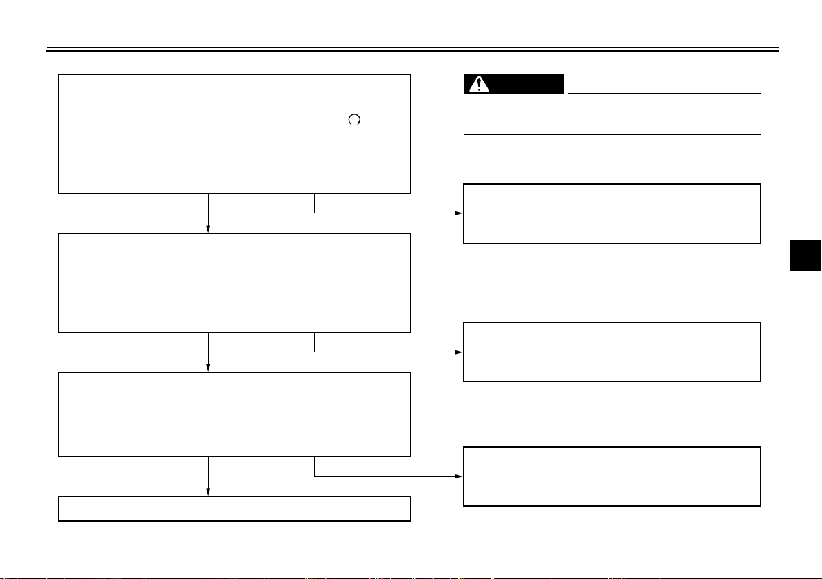
Periodically check the operation of the
ignition circuit cut-off system according
to the following procedure.
TIP
This check is most reliable if performed
with a warmed-up engine.
4-13
Page 33
INSTRUMENT AND CONTROL FUNCTIONS
With the engine turned off:
1. Move the sidestand down.
2. Make sure that the engine stop switch is set to “
3. Turn the key on.
4. Shift the transmission into the neutral position.
5. Push the start switch.
Does the engine start?
YES NO
With the engine still running:
6. Move the sidestand up.
7. Keep the clutch lever pulled.
8. Shift the transmission into gear.
9. Move the sidestand down.
Does the engine stall?
YES NO
After the engine has stalled:
10. Move the sidestand up.
11. Keep the clutch lever pulled.
12. Push the start switch.
Does the engine start?
YES NO
The system is OK. The motorcycle can be ridden.
WARNING
If a malfunction is noted, have a Yamaha
”.
dealer check the system before riding.
2
The neutral switch may not be working correctly.
The motorcycle should not be ridden until
checked by a Yamaha dealer.
3
4
5
The sidestand switch may not be working correctly.
The motorcycle should not be ridden until
checked by a Yamaha dealer.
6
7
8
The clutch switch may not be working correctly.
The motorcycle should not be ridden until
checked by a Yamaha dealer.
9
4-14
Page 34
FOR YOUR SAFETY – PRE-OPERATION CHECKS
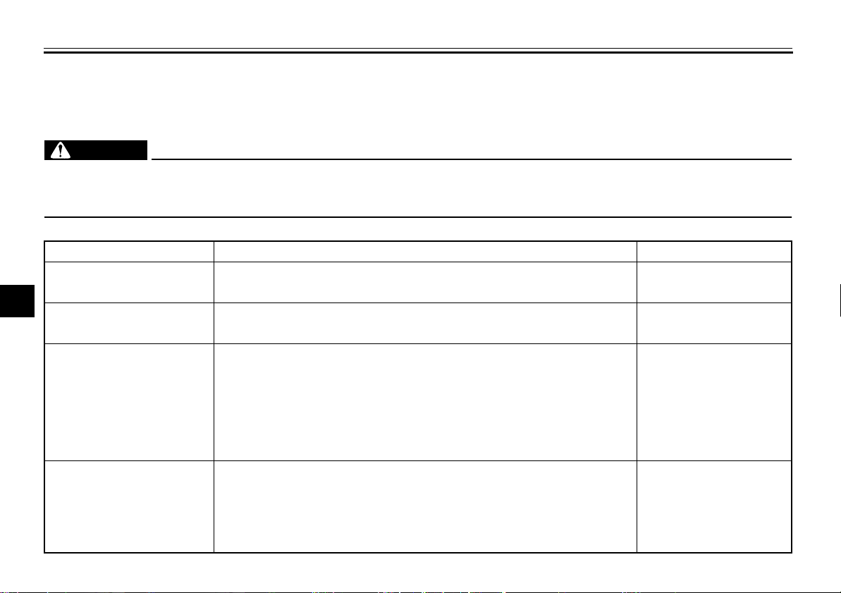
Inspect your vehicle each time you use it to make sure the vehicle is in safe operating condition. Always follow the inspection
and maintenance procedures and schedules described in the Owner’s Manual.
1
2
3
4
5
6
7
8
9
WARNING
Failure to inspect or maintain the vehicle properly increases the possibility of an accident or equipment damage.
Do not operate the vehicle if you find any problem. If a problem cannot be corrected by the procedures provided in
this manual, have the vehicle inspected by a Yamaha dealer.
Before using this vehicle, check the following points:
ITEM CHECKS PAGE
Fuel
Engine oil
Front brake
Rear brake
• Check fuel level in fuel tank.
• Refuel if necessary.
• Check fuel line for leakage.
• Check oil level in engine.
• If necessary, add recommended oil to specified level.
• Check vehicle for oil leakage.
• Check operation.
• If soft or spongy, have Yamaha dealer bleed hydraulic system.
• Check lever free play.
• Adjust if necessary.
• Check brake pads for wear.
• Replace if necessary.
• Check fluid level in reservoir.
• If necessary, add specified brake fluid to specified level.
• Check hydraulic system for leakage.
• Check operation.
• If soft or spongy, have Yamaha dealer bleed hydraulic system.
• Check brake pads for wear.
• Replace if necessary.
• Check fluid level in reservoir.
• If necessary, add specified brake fluid to specified level.
• Check hydraulic system for leakage.
5-1
4-7
7-12
7-20, 7-21, 7-22
7-21, 7-22
EAU15596
EWA11151
Page 35
ITEM CHECKS PAGE
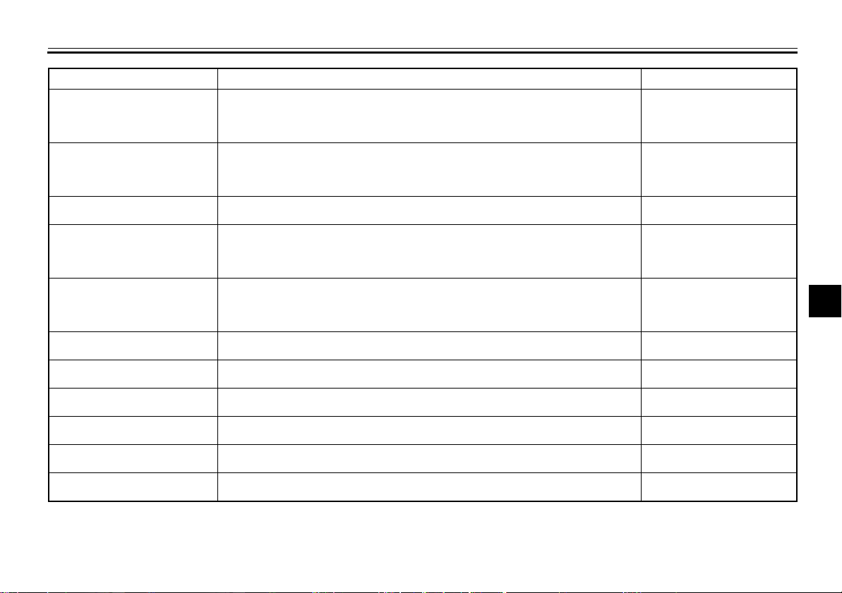
Clutch
Throttle grip
Control cables
Drive chain
Wheels and tires
Brake and shift pedals
Brake and clutch levers
Sidestand
Chassis fasteners
Instruments, lights, signals
and switches
Sidestand switch
FOR YOUR SAFETY – PRE-OPERATION CHECKS
• Check operation.
• Lubricate cable if necessary.
• Check lever free play.
• Adjust if necessary.
• Make sure that operation is smooth.
• Check throttle grip free play.
• If necessary, have Yamaha dealer adjust throttle grip free play and lubricate
cable and grip housing.
• Make sure that operation is smooth.
• Lubricate if necessary.
• Check chain slack.
• Adjust if necessary.
• Check chain condition.
• Lubricate if necessary.
• Check for damage.
• Check tire condition and tread depth.
• Check air pressure.
• Correct if necessary.
• Make sure that operation is smooth.
• Lubricate pedal pivoting points if necessary.
• Make sure that operation is smooth.
• Lubricate lever pivoting points if necessary.
• Make sure that operation is smooth.
• Lubricate pivot if necessary.
• Make sure that all nuts, bolts and screws are properly tightened.
• Tighten if necessary.
• Check operation.
• Correct if necessary.
• Check operation of ignition circuit cut-off system.
• If system is not working correctly, have Yamaha dealer check vehicle.
7-20
7-17, 7-26
7-25
7-23, 7-25
7-17, 7-19
7-26
7-27
7-27
—
—
4-12
2
3
4
5
6
7
8
9
5-2
Page 36
OPERATION AND IMPORTANT RIDING POINTS
Read the Owner’s Manual carefully to
become familiar with all controls. If
there is a control or function you do not
1
understand, ask your Yamaha dealer.
2
WARNING
Failure to familiarize yourself with
3
the controls can lead to loss of control, which could cause an accident
or injury.
4
5
6
7
8
9
EAU15951
EWA10271
EAU16015
Starting and warming up a cold engine
In order for the ignition circuit cut-off
system to enable starting, one of the
following conditions must be met:
●
The transmission is in the neutral
position.
●
The transmission is in gear with
the clutch lever pulled and the sidestand up.
See page 4-13 for more information.
1. Turn the fuel cock lever to “ON”.
2. Turn the key to “ON” and make
sure that the engine stop switch is
set to “”.
3. Shift the transmission into the neutral position. The neutral indicator
light should come on. If not, ask a
Yamaha dealer to check the electrical circuit.
4. Turn the starter (choke) on and
completely close the throttle. (See
page 4-9.)
5. Start the engine by pushing the
start switch.
If the engine fails to start, release
the start switch, wait a few seconds, and then try again. Each
starting attempt should be as short
as possible to preserve the battery. Do not crank the engine more
than 10 seconds on any one attempt.
6. After starting the engine, move the
starter (choke) back halfway.
7. When the engine is warm, turn the
starter (choke) off.
TIP
The engine is warm when it responds
quickly to the throttle with the starter
(choke) turned off.
ECA11042
NOTICE
For maximum engine life, never accelerate hard when the engine is
cold!
6-1
Page 37
OPERATION AND IMPORTANT RIDING POINTS
EAU16640
Starting a warm engine
Follow the same procedure as for starting a cold engine with the exception
that the starter (choke) is not required
when the engine is warm.
EAU16671
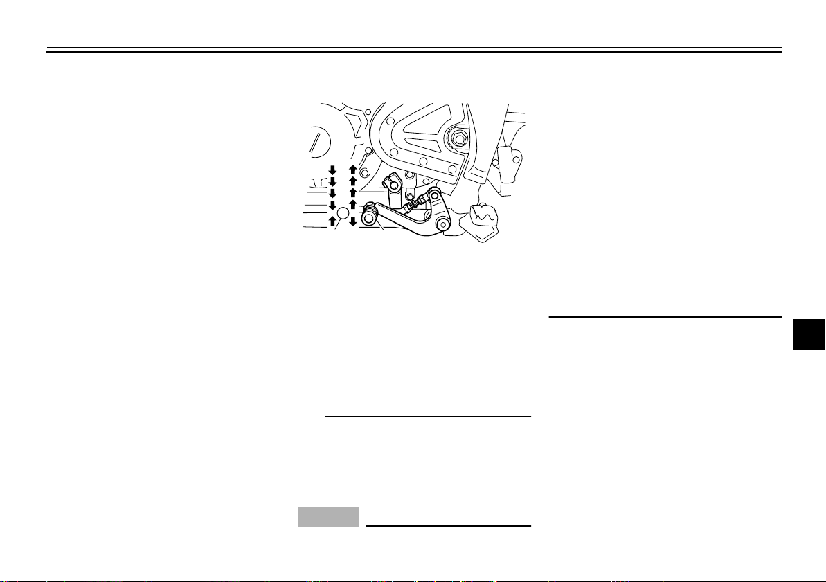
Shifting
5
4
3
2
N
1
1
1. Neutral position
2. Shift pedal
Shifting gears lets you control the
amount of engine power available for
starting off, accelerating, climbing hills,
etc.
The gear positions are shown in the illustration.
TIP
To shift the transmission into the neutral position, press the shift pedal down
repeatedly until it reaches the end of its
travel, and then slightly raise it.
NOTICE
●
Even with the transmission in
2
ECA10260
6-2
the neutral position, do not
coast for long periods of time
with the engine off, and do not
tow the motorcycle for long distances. The transmission is
properly lubricated only when
the engine is running. Inadequate lubrication may damage
the transmission.
●
Always use the clutch while
changing gears to avoid damaging the engine, transmission,
and drive train, which are not
designed to withstand the
shock of forced shifting.
2
3
4
5
6
7
8
9
Page 38
OPERATION AND IMPORTANT RIDING POINTS
Tips for reducing fuel consumption
Fuel consumption depends largely on
1
your riding style. Consider the following
tips to reduce fuel consumption:
●
2
3
4
5
6
7
8
9
Turn the starter (choke) off as
soon as possible.
●
Shift up swiftly, and avoid high engine speeds during acceleration.
●
Do not rev the engine while shifting
down, and avoid high engine
speeds with no load on the engine.
●
Turn the engine off instead of letting it idle for an extended length of
time (e.g., in traffic jams, at traffic
lights or at railroad crossings).
EAU16800
EAU16841
Engine break-in
There is never a more important period
in the life of your engine than the period
between 0 and 1600 km (1000 mi). For
this reason, you should read the following material carefully.
Since the engine is brand new, do not
put an excessive load on it for the first
1600 km (1000 mi). The various parts in
the engine wear and polish themselves
to the correct operating clearances.
During this period, prolonged full-throttle operation or any condition that might
result in engine overheating must be
avoided.
EAU17023
0–1000 km (0–600 mi)
Avoid prolonged operation above 1/3
throttle.
(600 mi) of operation, the engine oil
must be changed, and the oil filter
cartridge or element replaced.
NOTICE:
After 1000 km
[ECA11282]
1000–1600 km (600–1000 mi)
Avoid prolonged operation above 1/2
throttle.
1600 km (1000 mi) and beyond
The vehicle can now be operated normally.
ECA10270
NOTICE
If any engine trouble should occur
during the engine break-in period,
immediately have a Yamaha dealer
check the vehicle.
6-3
Page 39
EAU17171
Parking
When parking, stop the engine, remove
the key from the main switch, and then
turn the fuel cock lever to “OFF”.
WARNING
●
Since the engine and exhaust
system can become very hot,
park in a place where pedestrians or children are not likely to
touch them and be burned.
●
Do not park on a slope or on soft
ground, otherwise the vehicle
may overturn, increasing the
risk of a fuel leak and fire.
Do not park near grass or other
●
flammable materials which
might catch fire.
EWA10311
OPERATION AND IMPORTANT RIDING POINTS
2
3
4
5
6
7
8
6-4
9
Page 40
PERIODIC MAINTENANCE AND ADJUSTMENT
Periodic inspection, adjustment, and lubrication will keep your vehicle in the
safest and most efficient condition pos-
1
sible. Safety is an obligation of the vehicle owner/operator. The most important
2
points of vehicle inspection, adjustment, and lubrication are explained on
3
the following pages.
The intervals given in the periodic
maintenance charts should be simply
4
considered as a general guide under
normal riding conditions. However, de-
5
pending on the weather, terrain, geographical location, and individual use,
6
the maintenance intervals may need to
be shortened.
7
WARNING
Failure to properly maintain the ve-
8
hicle or performing maintenance activities incorrectly may increase
your risk of injury or death during
9
service or while using the vehicle. If
you are not familiar with vehicle service, have a Yamaha dealer perform
service.
EAU17244
EWA10321
EWA15122
WARNING
Turn off the engine when performing
maintenance unless otherwise
specified.
●
A running engine has moving
parts that can catch on body
parts or clothing and electrical
parts that can cause shocks or
fires.
●
Running the engine while servicing can lead to eye injury,
burns, fire, or carbon monoxide
poisoning – possibly leading to
death. See page 2-2 for more information about carbon monoxide.
EWA15460
WARNING
Brake discs, calipers, drums, and
linings can become very hot during
use. To avoid possible burns, let
brake components cool before
touching them.
EAU17302
Emission controls not only function to
ensure cleaner air, but are also vital to
proper engine operation and maximum
performance. In the following periodic
maintenance charts, the services related to emissions control are grouped
separately. These services require
specialized data, knowledge, and
equipment. Maintenance, replacement,
or repair of the emission control devices and systems may be performed by
any repair establishment or individual
that is certified (if applicable). Yamaha
dealers are trained and equipped to
perform these particular services.
7-1
Page 41
Owner’s tool kit
PERIODIC MAINTENANCE AND ADJUSTMENT
EAU17341
1
2
3
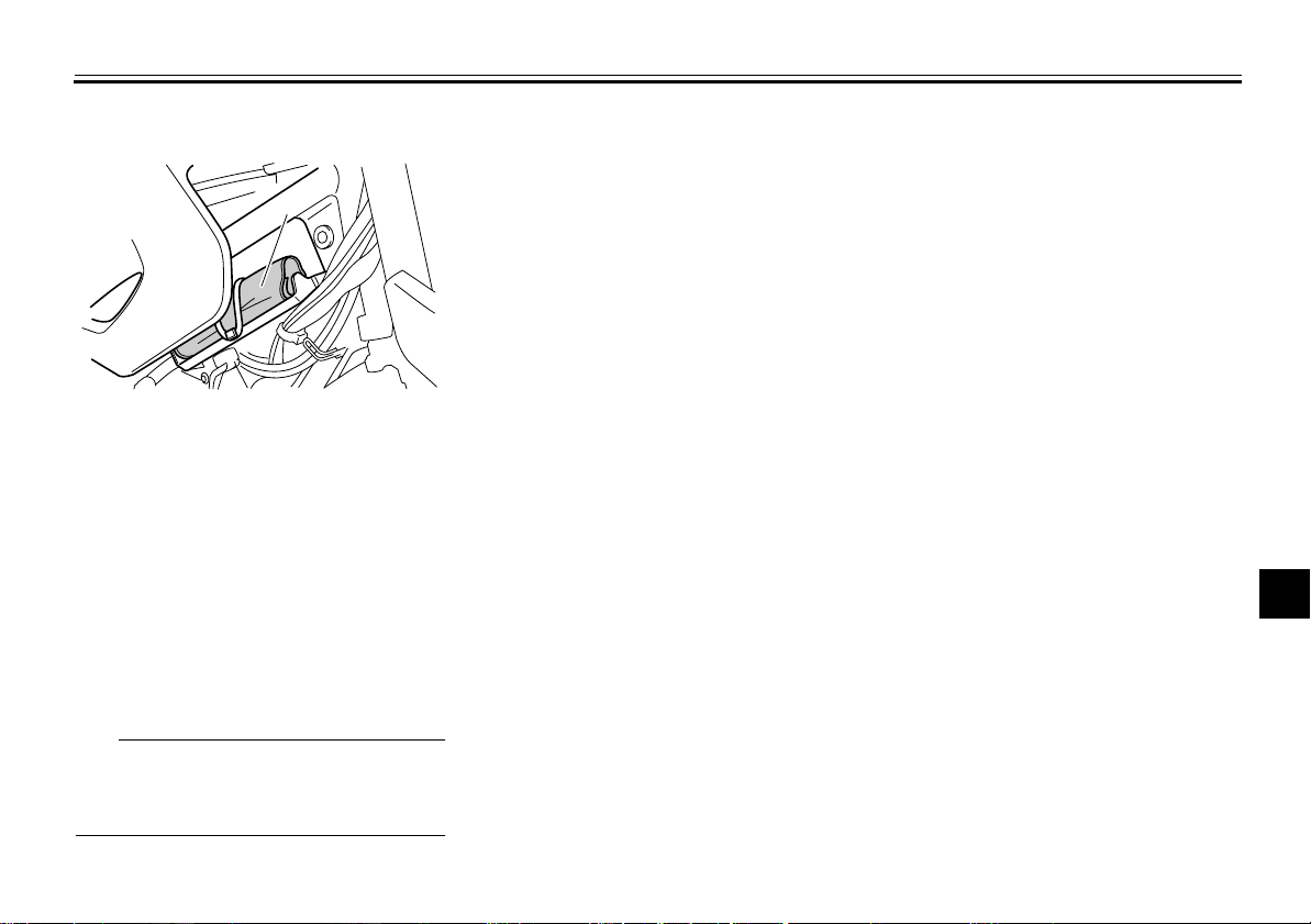
1. Owner’s tool kit
The owner’s tool kit is located behind
panel B. (See page 7-8.)
The service information included in this
manual and the tools provided in the
owner’s tool kit are intended to assist
you in the performance of preventive
maintenance and minor repairs. However, additional tools such as a torque
wrench may be necessary to perform
certain maintenance work correctly.
TIP
If you do not have the tools or experience required for a particular job, have
a Yamaha dealer perform it for you.
4
5
6
7
8
9
7-2
Page 42
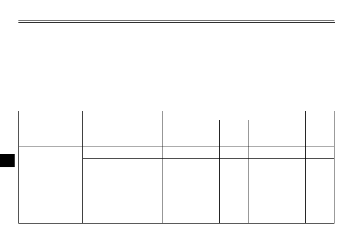
PERIODIC MAINTENANCE AND ADJUSTMENT
TIP
The annual checks must be performed every year, except if a kilometer-based maintenance, or for the UK, a
●
1
2
mileage-based maintenance, is performed instead.
From 50000 km (30000 mi), repeat the maintenance intervals starting from 10000 km (6000 mi).
●
Items marked with an asterisk should be performed by a Yamaha dealer as they require special tools, data and technical
●
skills.
EAU46861
3
Periodic maintenance chart for the emission control system
4
NO. ITEM CHECK OR MAINTENANCE JOB
5
1*
2
Fuel line
Spark plug
6
7
3*
Valves
8
4*
Carburetor
9
Muffler and exhaust
5*
pipe
Air induction
6*
system
• Check fuel hoses for cracks or
damage.
• Check condition.
• Clean and regap.
• Replace.
• Check valve clearance.
• Adjust.
• Check starter (choke) operation.
• Adjust engine idling speed.
• Check the screw clamp(s) for
looseness.
• Check the air cut-off valve, reed
valve, and hose for damage.
• Replace any damaged parts if
necessary.
1000 km
(600 mi)
√√√√√√
√√√√√
7-3
EAU46910
ODOMETER READING
10000 km
(6000 mi)
√√√√√
√√
√√√√
√√√√√
20000 km
(12000 mi)
√√
30000 km
(18000 mi)
40000 km
(24000 mi)
ANNUAL
CHECK
Page 43
PERIODIC MAINTENANCE AND ADJUSTMENT
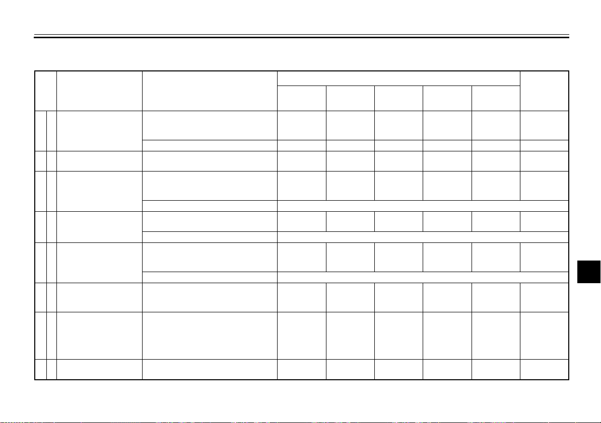
General maintenance and lubrication chart
NO. ITEM CHECK OR MAINTENANCE JOB
• Check condition and for
1
Air filter element
2
Clutch
3*
Front brake
4*
Rear brake
5*
Brake hoses
6*
Wheels
7*
Tires
8*
Wheel bearings
damage, and replace if
necessary.
• Replace.
• Check operation.
• Adjust.
• Check operation, fluid level and
vehicle for fluid leakage.
• Adjust brake lever free play.
• Replace brake pads. Whenever worn to the limit
• Check operation, fluid level and
vehicle for fluid leakage.
• Replace brake pads. Whenever worn to the limit
• Check for cracks or damage.
• Check for correct routing and
clamping.
• Replace. Every 4 years
• Check runout, spoke tightness
and for damage.
• Tighten spokes if necessary.
• Check tread depth and for
damage.
• Replace if necessary.
• Check air pressure.
• Correct if necessary.
• Check bearing for looseness or
damage.
EAU1770C
ODOMETER READING
1000 km
(600 mi)
√√√√√
√√√√√√
√√√√√√
√√√√√
10000 km
(6000 mi)
√√√√
√√√√√
√√√√√
√√√√
20000 km
(12000 mi)
√√
30000 km
(18000 mi)
40000 km
(24000 mi)
ANNUAL
CHECK
2
3
4
5
6
7
8
9
7-4
Page 44
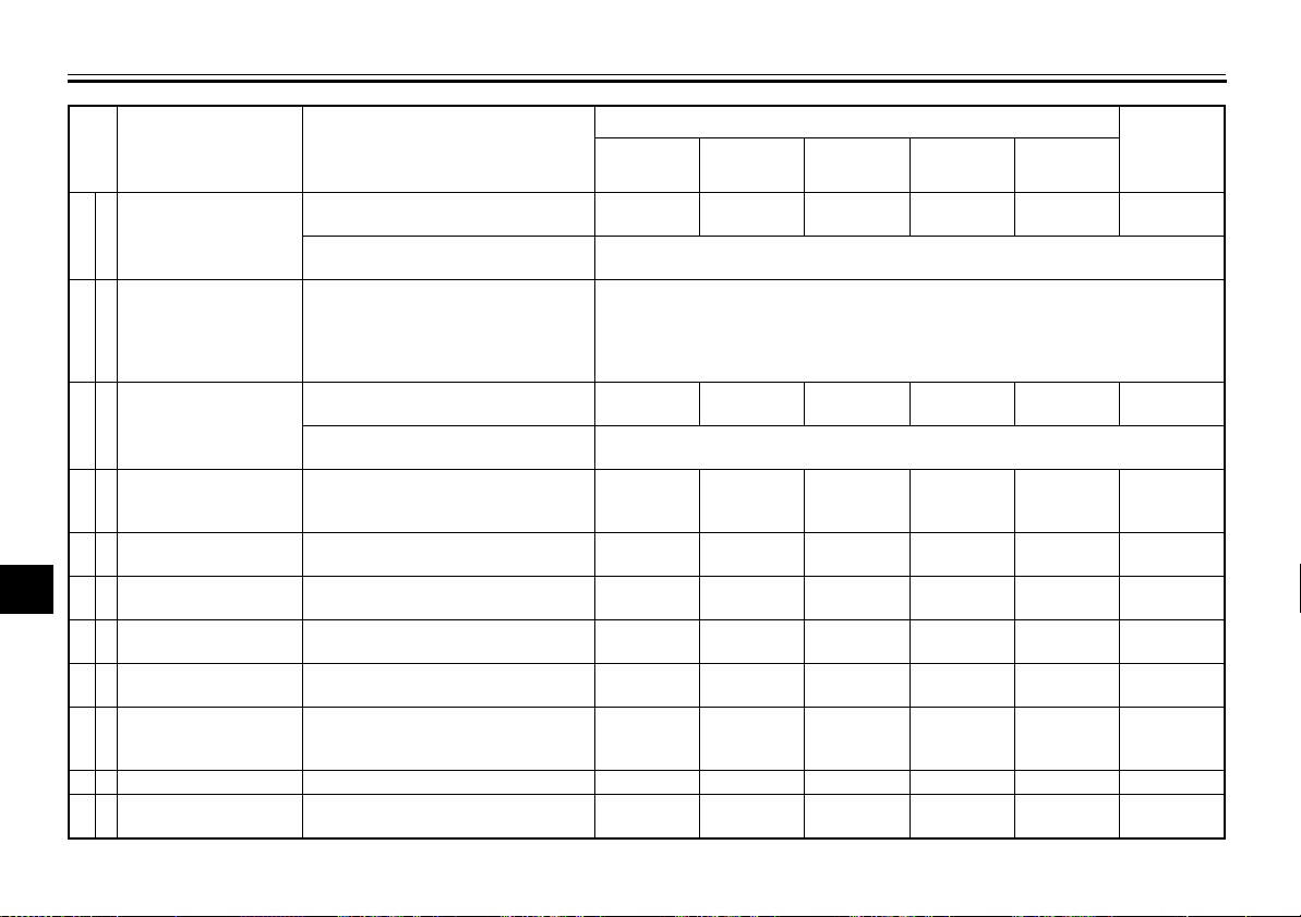
PERIODIC MAINTENANCE AND ADJUSTMENT
NO. ITEM CHECK OR MAINTENANCE JOB
1
Swingarm pivot
9*
bushes
2
10
3
Drive chain
4
11 *
Steering bearings
5
12 *
Chassis fasteners
6
7
8
Brake lever pivot
13
shaft
Brake pedal pivot
14
shaft
Clutch lever pivot
15
shaft
Shift pedal pivot
16
shaft
9
17
Sidestand
18 *
Sidestand switch
19 *
Front fork
• Check bush assemblies for
looseness.
• Lubricate with
lithium-soap-based grease.
• Check chain slack, alignment
and condition.
• Adjust and lubricate chain with a
special O-ring chain lubricant
thoroughly.
• Check bearing play and steering
for roughness.
• Lubricate with
lithium-soap-based grease.
• Make sure that all nuts, bolts
and screws are properly
tightened.
• Lubricate with silicone grease.
• Lubricate with
lithium-soap-based grease.
• Lubricate with
lithium-soap-based grease.
• Lubricate with
lithium-soap-based grease.
• Check operation.
• Lubricate with
lithium-soap-based grease.
• Check operation.
• Check operation and for oil
leakage.
ODOMETER READING
1000 km
(600 mi)
Every 500 km (300 mi) and after washing the motorcycle, riding in the rain or
√√√√√
√√√√√√
10000 km
(6000 mi)
√√√√
√√√√√
√√√√√
√√√√√
√√√√√
√√√√√
√√√√√
√√√√
20000 km
(12000 mi)
Every 10000 km (6000 mi)
riding in wet areas
Every 50000 km (30000 mi)
30000 km
(18000 mi)
40000 km
(24000 mi)
ANNUAL
CHECK
7-5
Page 45
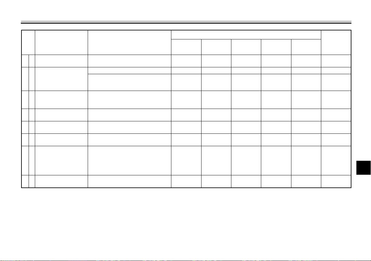
PERIODIC MAINTENANCE AND ADJUSTMENT
NO. ITEM CHECK OR MAINTENANCE JOB
Shock absorber
20 *
assembly
Rear suspension
relay arm and
21 *
connecting arm
pivoting points
22
Engine oil
Engine oil filter
23
element
Front and rear brake
24 *
switches
Moving parts and
25
cables
26 *
Throttle grip
Lights, signals and
27 *
switches
• Check operation and shock
absorber for oil leakage.
• Check operation.
• Lubricate with
lithium-soap-based grease.
• Change.
• Check oil level and vehicle for oil
leakage.
• Replace.
• Check operation.
• Lubricate.
• Check operation.
• Check throttle grip free play, and
adjust if necessary.
• Lubricate cable and grip
housing.
• Check operation.
• Adjust headlight beam.
ODOMETER READING
1000 km
(600 mi)
√√√√√√
√√√
√√√√√√
√√√√√√
10000 km
(6000 mi)
√√√√
√√√√
√√√√√
√√√√√
20000 km
(12000 mi)
√√
30000 km
(18000 mi)
40000 km
(24000 mi)
ANNUAL
CHECK
2
3
4
5
6
7
8
9
7-6
Page 46
PERIODIC MAINTENANCE AND ADJUSTMENT
TIP
Air filter
●
1
2
3
4
5
6
7
8
• This model’s air filter is equipped with a disposable oil-coated paper element, which must not be cleaned with compressed air to avoid damaging it.
• The air filter element needs to be replaced more frequently when riding in unusually wet or dusty areas.
Hydraulic brake service
●
• Regularly check and, if necessary, correct the brake fluid level.
• Every two years replace the internal components of the brake master cylinders and calipers, and change the brake
fluid.
• Replace the brake hoses every four years and if cracked or damaged.
EAU18680
9
7-7
Page 47
PERIODIC MAINTENANCE AND ADJUSTMENT
1
1
EAU18722
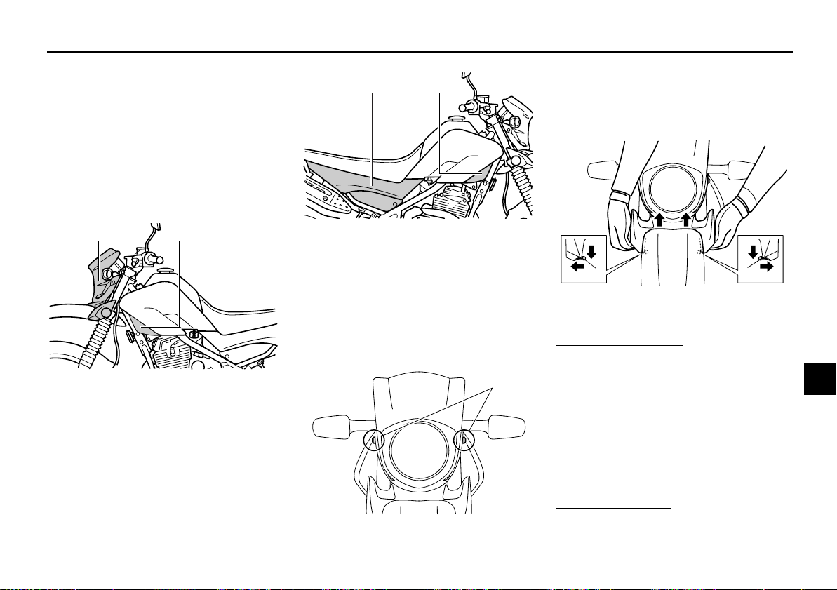
Removing and installing the cowling and panels
The cowling and panels shown need to
be removed to perform some of the
maintenance jobs described in this
chapter. Refer to this section each time
the cowling or a panel needs to be removed and installed.
1
1. Cowling A
2. Panel A
2
2
1. Panel B
2. Panel C
Cowling A
To remove the cowling
1. Remove the bolts.
1
bottom of the cowling by pulling it
downward, and then pull the cowling forward as shown.
2
3
4
2. Unhook both projections at the
EAU44841
1. Projection
To install the cowling
5
6
1. Place the cowling in the original
1
2. Install the bolts.
EAU44851
Panels A and B
position.
7
8
9
To remove a panel
1. Remove the screw and collar.
1. Bolt
7-8
Page 48
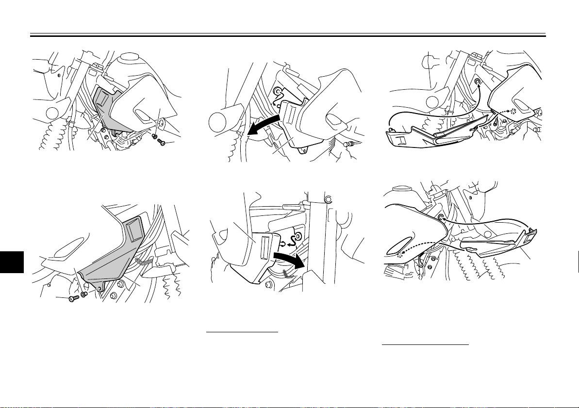
PERIODIC MAINTENANCE AND ADJUSTMENT
1
1
by pulling it forward as shown.
1
2
3
4
1. Panel A
2. Collar
3. Screw
1
5
6
7
2
8
1
1. Screw
9
2. Collar
3. Panel B
2. Pull the front part of the panel outward, and then remove the panel
2
3
1
1. Panel A
1. Panel A
1
3
1. Panel B
To install a panel
Place the collar and panel in their original position, and then install the screw.
7-9
1. Panel B
Panel C
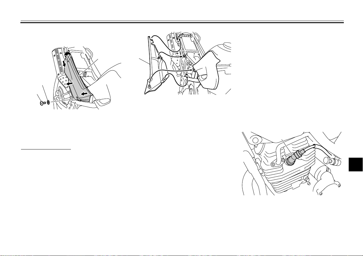
To remove the panel
1. Remove the seat. (See
page 4-10.)
Page 49
PERIODIC MAINTENANCE AND ADJUSTMENT
1
2. Remove the bolt and washer, and
then remove the panel as shown.
3
2
1
1. Bolt
2. Washer
3. Panel C
To install the panel
1. Place the panel in the original position, and then install the washer
and bolt.
1
1. Panel C
2. Install the seat.
EAU19604
Checking the spark plug
The spark plug is an important engine
component, which is easy to check.
Since heat and deposits will cause any
spark plug to slowly erode, the spark
plug should be removed and checked
in accordance with the periodic maintenance and lubrication chart. In addition,
the condition of the spark plug can reveal the condition of the engine.
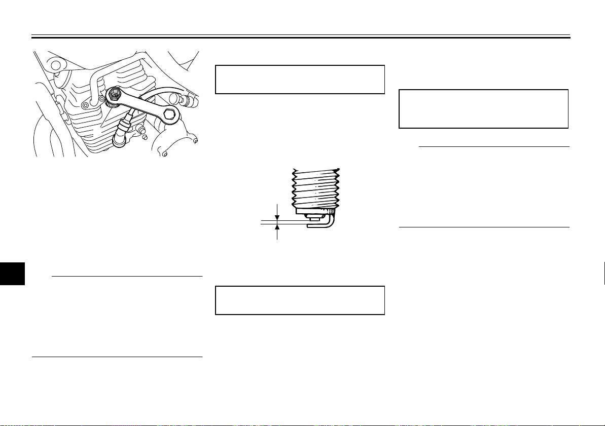
To remove the spark plug
1. Remove the spark plug cap.
1. Spark plug cap
2
3
4
5
6
7
8
9
7-10
2. Remove the spark plug as shown,
with the spark plug wrench included in the owner’s tool kit.
Page 50
PERIODIC MAINTENANCE AND ADJUSTMENT
1
2
1
3
1. Spark plug wrench
4
To check the spark plug
1. Check that the porcelain insulator
5
around the center electrode of the
spark plug is a medium-to-light tan
6
(the ideal color when the vehicle is
ridden normally).
7
TIP
If the spark plug shows a distinctly different color, the engine could be oper-
8
ating improperly. Do not attempt to
diagnose such problems yourself. In-
9
stead, have a Yamaha dealer check
the vehicle.
2. Check the spark plug for electrode
erosion and excessive carbon or
other deposits, and replace it if
necessary.
Specified spark plug:
NGK/DR7EA
3. Measure the spark plug gap with a
wire thickness gauge and, if necessary, adjust the gap to specification.
1
1. Spark plug gap
Spark plug gap:
0.6–0.7 mm (0.024–0.028 in)
To install the spark plug
1. Clean the surface of the spark plug
gasket and its mating surface, and
then wipe off any grime from the
spark plug threads.
2. Install the spark plug with the
spark plug wrench, and then tighten it to the specified torque.
Tightening torque:
Spark plug:
18 Nm (1.8 m·kgf, 13 ft·lbf)
TIP
If a torque wrench is not available when
installing a spark plug, a good estimate
of the correct torque is 1/4–1/2 turn
past finger tight. However, the spark
plug should be tightened to the specified torque as soon as possible.
3. Install the spark plug cap.
7-11
Page 51
PERIODIC MAINTENANCE AND ADJUSTMENT
1
1
2
1
EAU37805
Engine oil and oil filter element
The engine oil level should be checked
before each ride. In addition, the oil
must be changed and the oil filter element replaced at the intervals specified
in the General periodic maintenance
and lubrication chart.
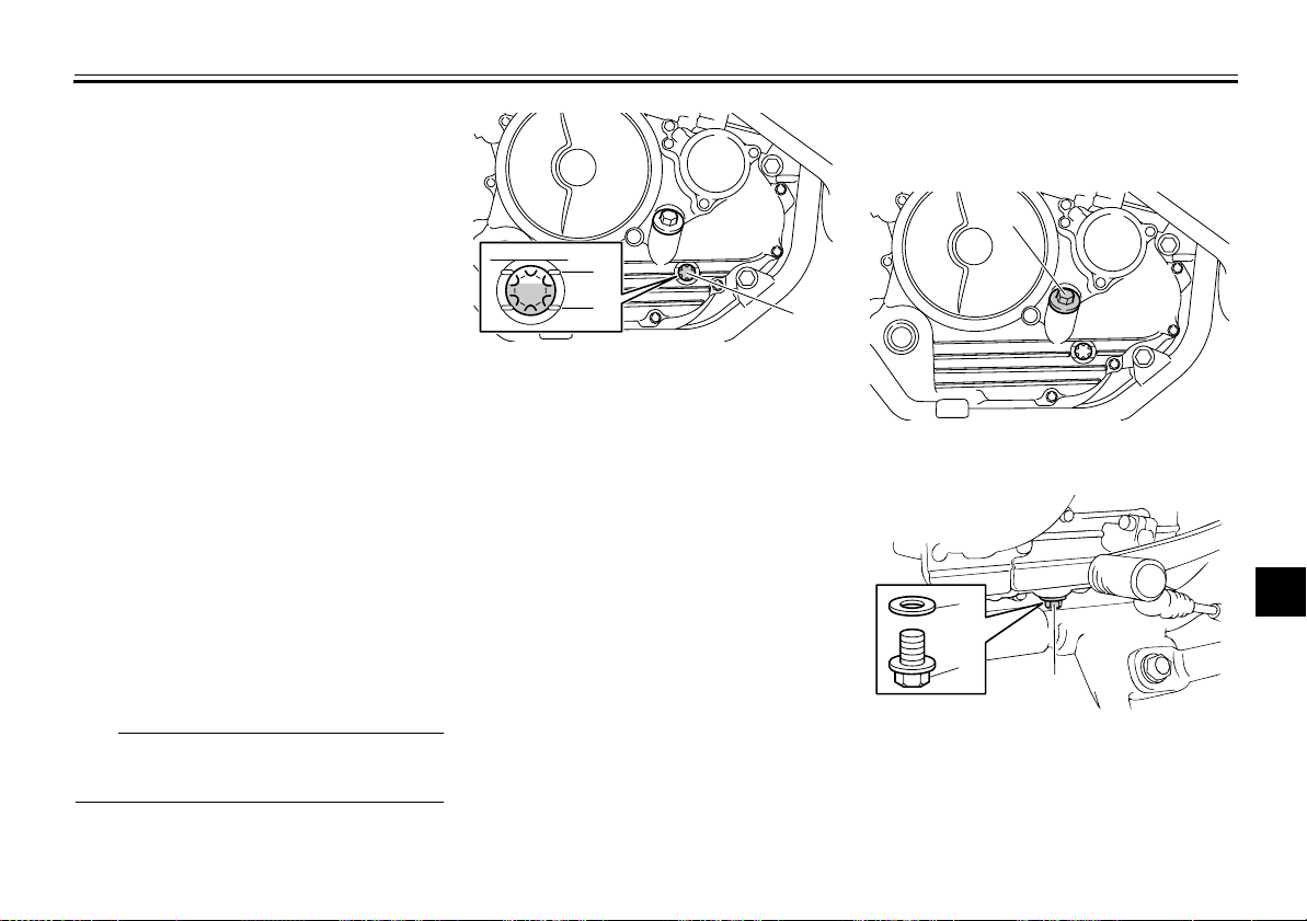
To check the engine oil level
1. Place the vehicle on a level surface and hold it in an upright position. A slight tilt to the side can
result in a false reading.
2. Start the engine, warm it up for
several minutes, and then turn it
off.
3. Wait a few minutes until the oil settles, and then check the oil level
through the check window located
at the bottom-right side of the
crankcase.
TIP
The engine oil should be between the
minimum and maximum level marks.
1
2
1. Maximum level mark
2. Minimum level mark
3. Engine oil level check window
4. If the engine oil is below the minimum level mark, add sufficient oil
of the recommended type to raise
it to the correct level.
To change the engine oil (with or
without oil filter element replacement)
1. Place the vehicle on a level surface.
2. Start the engine, warm it up for
several minutes, and then turn it
off.
3. Place an oil pan under the engine
to collect the used oil.
7-12
3
4. Remove the engine oil filler bolt,
engine oil drain bolt and its gasket
to drain the oil from the crankcase.
1. Engine oil filler bolt
1. Engine oil drain bolt
2. Gasket
2
3
4
5
6
7
8
9
Page 52
PERIODIC MAINTENANCE AND ADJUSTMENT
2
1
1
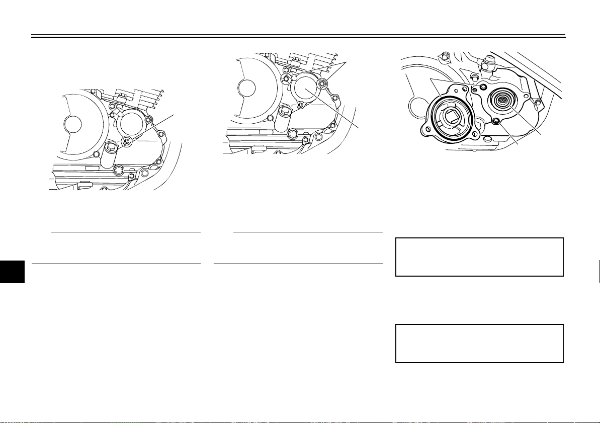
5. Remove the oil filter element drain
bolt to drain the oil from the oil filter
element.
1
1
2
3
1. Oil filter element cover bolt
4
1. Oil filter element drain bolt
5
TIP
Skip steps 6–8 if the oil filter element is
6
not being replaced.
7
6. Remove the oil filter element cover
by removing the bolts.
8
9
2. Oil filter element cover
7. Remove and replace the oil filter
element and O-rings.
TIP
Make sure that the O-rings are properly
seated.
1
2
1. O-ring
2. Oil filter element
8. Install the oil filter element cover by
installing the bolts, and then tighten the bolts to the specified torque.
Tightening torque:
Oil filter element cover bolt:
10 Nm (1.0 m·kgf, 7.2 ft·lbf)
9. Install the engine oil drain bolt and
its new gasket, and then tighten
the bolt to the specified torque.
Tightening torque:
Engine oil drain bolt:
20 Nm (2.0 m·kgf, 14 ft·lbf)
10. Install the oil filter element drain
bolt, and then tighten the bolt to the
7-13
Page 53
PERIODIC MAINTENANCE AND ADJUSTMENT
specified torque.
Tightening torque:
Oil filter element drain bolt:
10 Nm (1.0 m·kgf, 7.2 ft·lbf)
11. Refill with the specified amount of
the recommended engine oil, and
then install and tighten the oil filler
bolt.
Recommended oil:
See page 9-1.
Oil quantity:
Without oil filter element replacement:
1.20 L (1.27 US qt, 1.06 Imp.qt)
With oil filter element replacement:
1.30 L (1.37 US qt, 1.14 Imp.qt)
TIP
Be sure to wipe off spilled oil on any
parts after the engine and exhaust system have cooled down.
ECA11620
NOTICE
●
In order to prevent clutch slippage (since the engine oil also
lubricates the clutch), do not
mix any chemical additives. Do
not use oils with a diesel specification of “CD” or oils of a higher quality than specified. In
addition, do not use oils labeled
“ENERGY CONSERVING II” or
higher.
●
Make sure that no foreign material enters the crankcase.
12. Start the engine, and then let it idle
for several minutes while checking
it for oil leakage. If oil is leaking, immediately turn the engine off and
check for the cause.
13. Turn the engine off, and then
check the oil level and correct it if
necessary.
EAU44651
Replacing the air filter element and cleaning the check hose
The air filter element should be replaced at the intervals specified in the
periodic maintenance and lubrication
chart. Replace the air filter element
more frequently if you are riding in unusually wet or dusty areas. In addition,
the air filter check hose must be frequently checked and cleaned if necessary.
To replace the air filter element
1. Remove the seat. (See
page 4-10.)
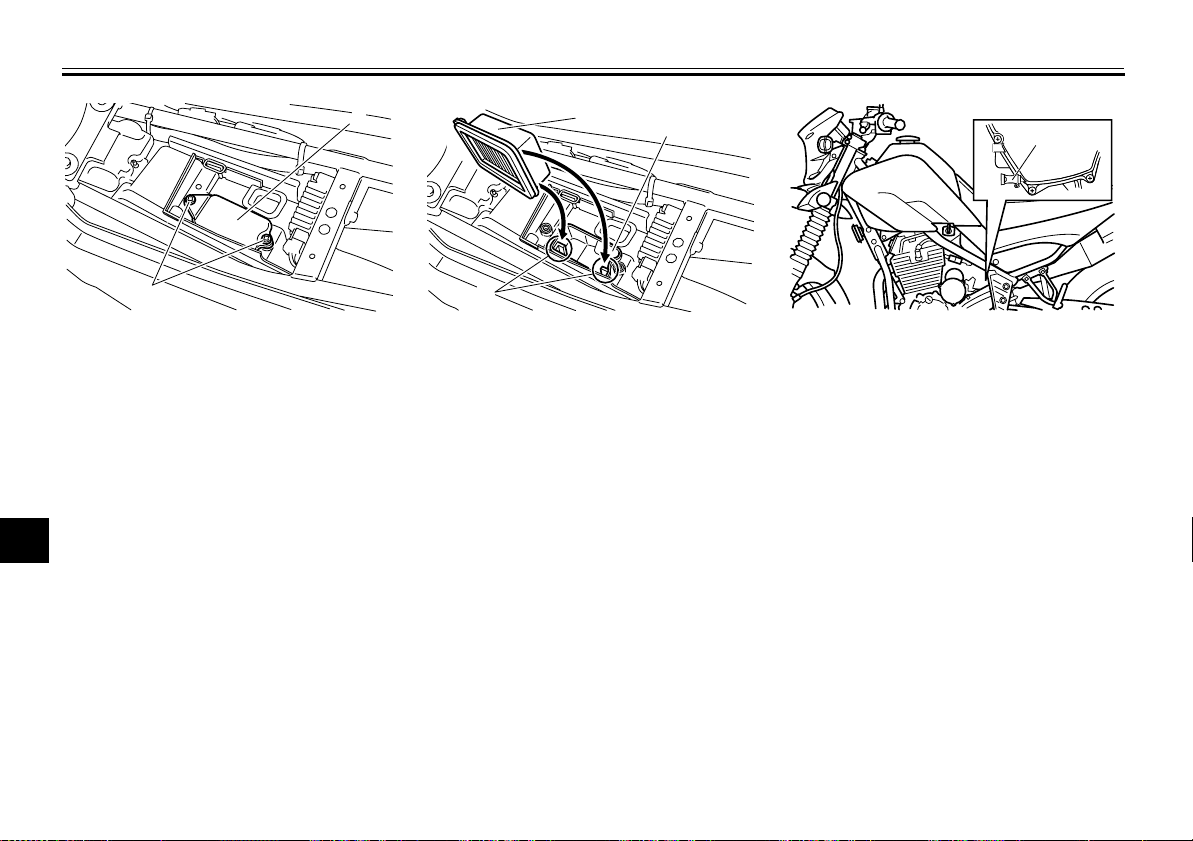
2. Remove the air filter case cover by
removing the screws.
2
3
4
5
6
7
8
9
7-14
Page 54
PERIODIC MAINTENANCE AND ADJUSTMENT
1
1
2
1
3
1. Screw
2. Air filter case cover
4
3. Pull the air filter element out.
4. Insert a new air filter element into
5
the air filter case as shown.
6
NOTICE:
filter element is properly seated
in the air filter case. The engine
7
should never be operated without the air filter element in-
8
stalled, otherwise the piston(s)
and/or cylinder(s) may become
9
excessively worn.
Make sure that the air
[ECA10481]
2
1
2
3
1. Air filter element
2. Air filter case
3. Slot
5. Install the air filter case cover by installing the screws.
6. Install the seat.
To clean the air filter check hose
1. Check the hose on the side of the
air filter case for accumulated dirt
or water.
1. Air filter check hose
2. If dirt or water is visible, remove
the hose, clean it, and then install
it.
7-15
Page 55
PERIODIC MAINTENANCE AND ADJUSTMENT
(a)
(b)
1
EAU21280
Adjusting the carburetor
The carburetor is an important part of
the engine and requires very sophisticated adjustment. Therefore, most carburetor adjustments should be left to a
Yamaha dealer, who has the necessary professional knowledge and experience. The adjustment described in the
following section, however, may be serviced by the owner as part of routine
maintenance.
ECA10550
NOTICE
The carburetor has been set and extensively tested at the Yamaha factory. Changing these settings
without sufficient technical knowledge may result in poor performance of or damage to the engine.
EAU21340
Adjusting the engine idling speed
The engine idling speed must be
checked and, if necessary, adjusted as
follows at the intervals specified in the
periodic maintenance and lubrication
chart.
The engine should be warm before
making this adjustment.
TIP
The engine is warm when it quickly
●
responds to the throttle.
A diagnostic tachometer is needed
●
to make this adjustment.
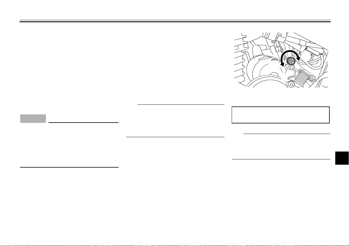
1. Attach the tachometer to the spark
plug lead.
2. Check the engine idling speed
and, if necessary, adjust it to specification by turning the throttle stop
screw. To increase the engine
idling speed, turn the screw in direction (a). To decrease the engine idling speed, turn the screw in
direction (b).
1. Throttle stop screw
Engine idling speed:
1300–1500 r/min
TIP
If the specified idling speed cannot be
obtained as described above, have a
Yamaha dealer make the adjustment.
2
3
4
5
6
7
8
9
7-16
Page 56
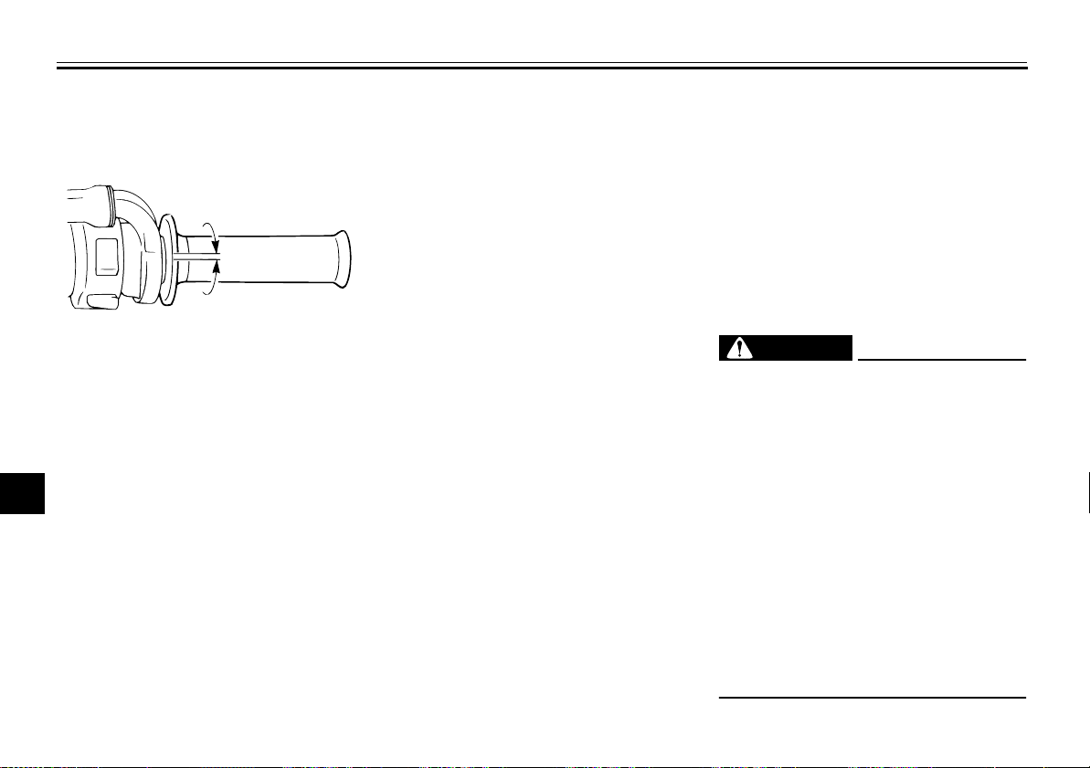
PERIODIC MAINTENANCE AND ADJUSTMENT
Checking the throttle grip free play
1
2
1
3
4
1. Throttle grip free play
5
The throttle grip free play should measure 3.0–5.0 mm (0.12–0.20 in) at the
6
inner edge of the throttle grip. Periodically check the throttle grip free play
7
and, if necessary, have a Yamaha
dealer adjust it.
8
9
EAU21384
EAU21401
Valve clearance
The valve clearance changes with use,
resulting in improper air-fuel mixture
and/or engine noise. To prevent this
from occurring, the valve clearance
must be adjusted by a Yamaha dealer
at the intervals specified in the periodic
maintenance and lubrication chart.
EAU21604
Tires
To maximize the performance, durability, and safe operation of your motorcycle, note the following points regarding
the specified tires.
Tire air pressure
The tire air pressure should be checked
and, if necessary, adjusted before each
ride.
WARNING
Operation of this vehicle with improper tire pressure may cause severe injury or death from loss of
control.
The tire air pressure must be
●
checked and adjusted on cold
tires (i.e., when the temperature
of the tires equals the ambient
temperature).
The tire air pressure must be ad-
●
justed in accordance with the
riding speed and with the total
weight of rider, passenger, cargo, and accessories approved
for this model.
EWA10503
7-17
Page 57
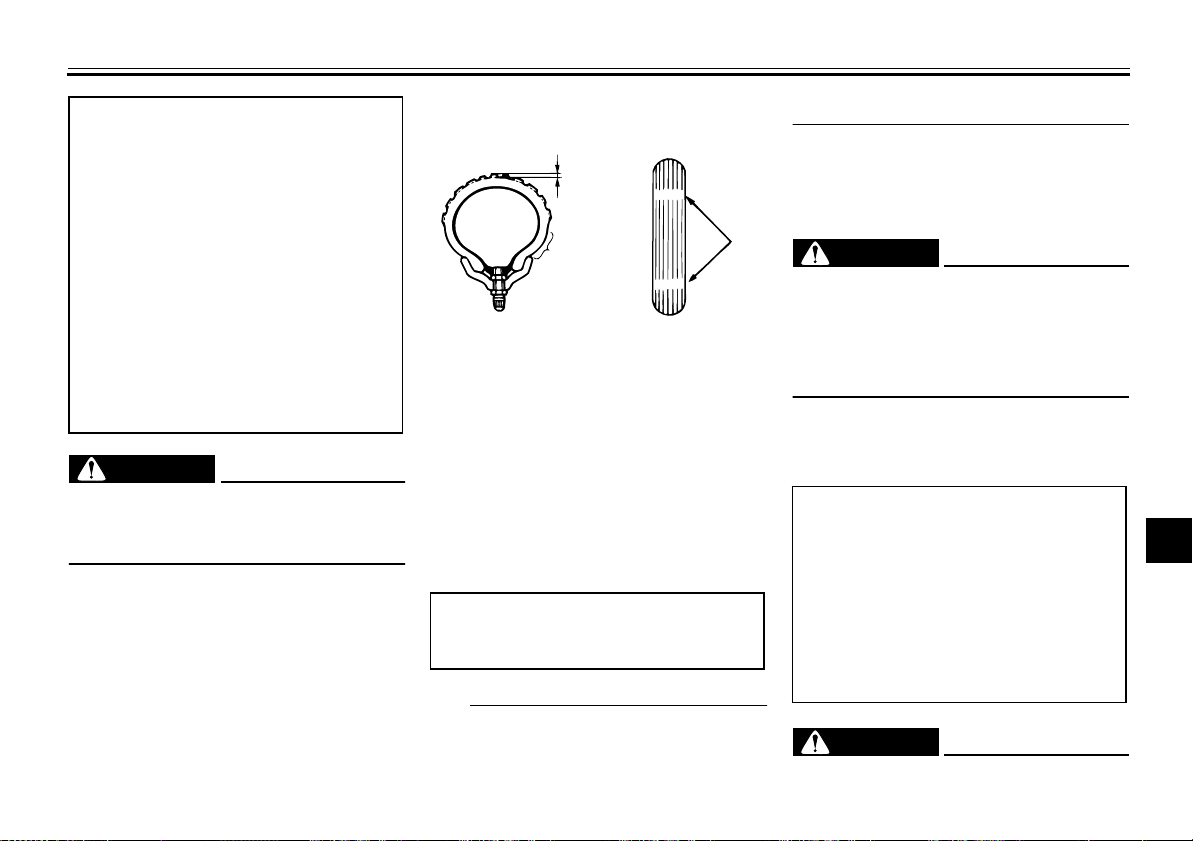
PERIODIC MAINTENANCE AND ADJUSTMENT
Tire air pressure (measured on cold
tires):
0–90 kg (0–198 lb):
Front:
125 kPa (1.25 kgf/cm
Rear:
150 kPa (1.50 kgf/cm2, 22 psi)
90–160 kg (198–353 lb):
Front:
150 kPa (1.50 kgf/cm2, 22 psi)
Rear:
175 kPa (1.75 kgf/cm2, 25 psi)
Maximum load*:
151 kg (333 lb)
* Total weight of rider, passenger, car-
go and accessories
2
, 18 psi)
EWA10511
WARNING
Never overload your vehicle. Operation of an overloaded vehicle could
cause an accident.
Tire inspection
1
2
1. Tire tread depth
2. Tire sidewall
3. Tire wear indicator
The tires must be checked before each
ride. If the tire shows crosswise lines
(minimum tread depth), if the tire has a
nail or glass fragments in it, or if the
sidewall is cracked, have a Yamaha
dealer replace the tire immediately.
Minimum tire tread depth (front and
rear):
1.0 mm (0.04 in)
TIP
The tire tread depth limits may differ
from country to country. Always comply
7-18
3
with the local regulations.
Tire information
This motorcycle is equipped with tube
tires.
EWA10461
WARNING
The front and rear tires should be of
the same make and design, otherwise the handling characteristics of
the vehicle may be different, which
could lead to an accident.
After extensive tests, only the tires listed below have been approved for this
model by Yamaha Motor Co., Ltd.
Front tire:
Size:
2.75-21 45P
Manufacturer/model:
BRIDGESTONE/TW-301
Rear tire:
Size:
120/80-18M/C 62P
Manufacturer/model:
BRIDGESTONE/TW-302
EWA10562
WARNING
●
It is dangerous to ride with a
2
3
4
5
6
7
8
9
Page 58
PERIODIC MAINTENANCE AND ADJUSTMENT
worn-out tire. When a tire tread
begins to show crosswise lines,
have a Yamaha dealer replace
the tire immediately.
1
●
The replacement of all wheel
and brake-related parts, includ-
2
ing the tires, should be left to a
Yamaha dealer, who has the
necessary professional knowl-
3
4
edge and experience.
●
It is not recommended to patch
a punctured tube. If unavoidable, however, patch the tube
5
very carefully and replace it as
soon as possible with a
high-quality product.
6
●
Ride at moderate speeds after
changing a tire since the tire
7
surface must first be “broken
in” for it to develop its optimal
8
characteristics.
Spoke wheels
WARNING
The wheels on this model are not designed for use with tubeless tires.
Do not attempt to use tubeless tires
on this model.
To maximize the performance, durability, and safe operation of your motorcycle, note the following points regarding
the specified wheels.
●
The wheel rims should be checked
for cracks, bends, warpage or other damage, and the spokes for
looseness or damage before each
ride. If any damage is found, have
a Yamaha dealer replace the
wheel. Do not attempt even the
smallest repair to the wheel. A deformed or cracked wheel must be
EAU21943
EWA10610
ened tire life.
replaced.
●
9
The wheel should be balanced
whenever either the tire or wheel
has been changed or replaced. An
unbalanced wheel can result in
poor performance, adverse handling characteristics, and a short-
7-19
Page 59
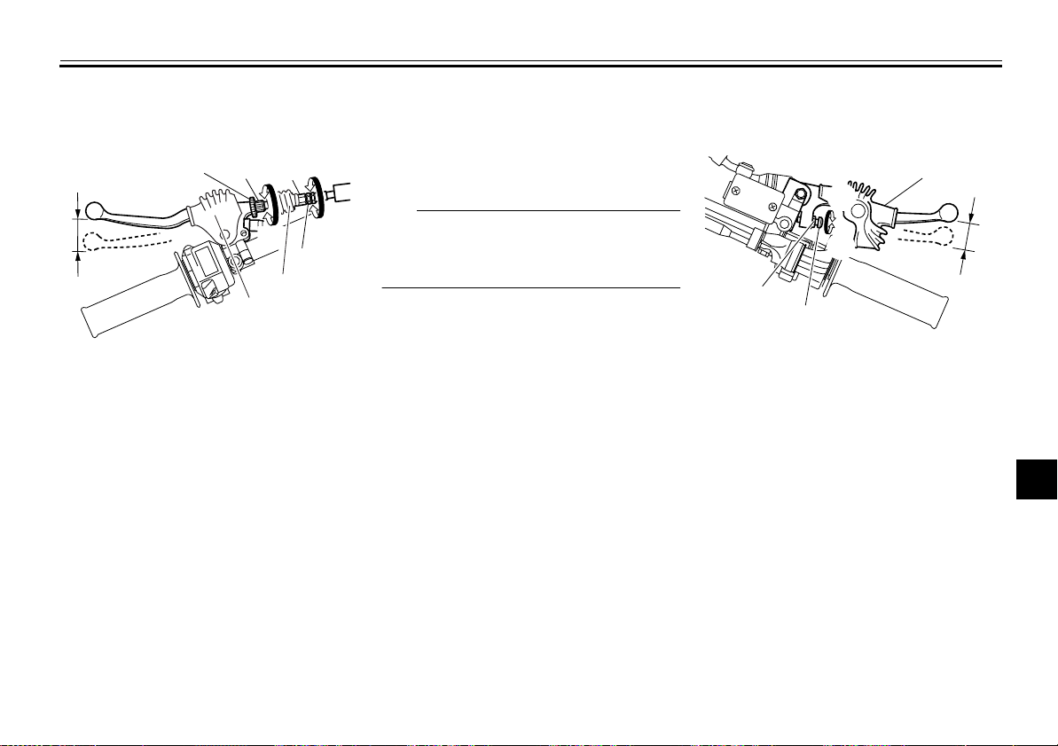
PERIODIC MAINTENANCE AND ADJUSTMENT
3
1
2
4
(b)
(a)
EAU22034
Adjusting the clutch lever free play
2
1
6
(a)
(b)
5
1. Locknut (clutch lever)
2. Clutch lever free play adjusting bolt
3. Clutch lever free play adjusting nut
4. Locknut (clutch cable)
5. Rubber cover
6. Clutch lever free play
The clutch lever free play should measure 10.0–15.0 mm (0.39–0.59 in) as
shown. Periodically check the clutch lever free play and, if necessary, adjust it
as follows.
1. Slide the rubber cover back at the
clutch lever.
2. Loosen the locknut.
3. To increase the clutch lever free
(b)
3
4
5
(a)
play, turn the clutch lever free play
adjusting bolt in direction (a). To
decrease the clutch lever free play,
turn the adjusting bolt in direction
(b).
TIP
If the specified clutch lever free play
could be obtained as described above,
skip steps 4–7.
4. Fully turn the adjusting bolt in direction (a) to loosen the clutch cable.
5. Loosen the locknut further down
the clutch cable.
6. To increase the clutch lever free
play, turn the clutch lever free play
adjusting nut in direction (a). To
decrease the clutch lever free play,
turn the adjusting nut in direction
(b).
7. Tighten the locknut at the clutch
cable.
8. Tighten the locknut at the clutch lever, and then slide the rubber cover to its original position.
7-20
EAU48442
Adjusting the brake lever free play
1. Locknut
2. Brake lever free play adjusting screw
3. Brake lever free play
4. Rubber cover
The brake lever free play should measure 2.0–5.0 mm (0.08–0.20 in) as
shown. Periodically check the brake lever free play and, if necessary, adjust it
as follows.
1. Slide the rubber cover back at the
brake lever.
2. Loosen the locknut.
3. To increase the brake lever free
play, turn the brake lever free play
adjusting screw in direction (a). To
2
3
4
5
6
7
8
9
Page 60
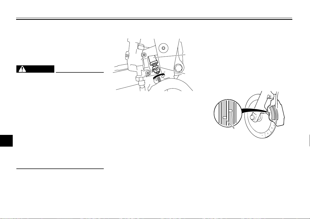
PERIODIC MAINTENANCE AND ADJUSTMENT
1
decrease the brake lever free play,
turn the adjusting screw in direction (b).
4. Tighten the locknut, and then slide
1
the rubber cover back to its original
position.
2
3
WARNING
●
After adjusting the brake lever
free play, check the free play
and make sure that the brake is
4
5
working properly.
●
A soft or spongy feeling in the
brake lever can indicate the
presence of air in the hydraulic
system. If there is air in the hy-
6
draulic system, have a Yamaha
dealer bleed the system before
7
operating the motorcycle. Air in
the hydraulic system will dimin-
8
ish the braking performance,
which may result in loss of control and an accident.
9
EWA10630
EAU22273
Brake light switches
1
(b)
(a)
1. Rear brake light switch
2. Rear brake light switch adjusting nut
The brake light, which is activated by
the brake pedal and brake lever, should
come on just before braking takes effect. If necessary, adjust the rear brake
light switch as follows, but the front
brake light switch should be adjusted
by a Yamaha dealer.
Turn the rear brake light switch adjusting nut while holding the rear brake light
switch in place. To make the brake light
come on earlier, turn the adjusting nut
in direction (a). To make the brake light
come on later, turn the adjusting nut in
direction (b).
2
EAU22392
Checking the front and rear brake pads
The front and rear brake pads must be
checked for wear at the intervals specified in the periodic maintenance and
lubrication chart.
EAU22420
Front brake pads
1. Wear indicator groove
Each front brake pad is provided with a
wear indicator groove, which allows
you to check the brake pad wear without having to disassemble the brake.
To check the brake pad wear, check
the wear indicator groove. If a brake
pad has worn to the point that the wear
7-21
Page 61
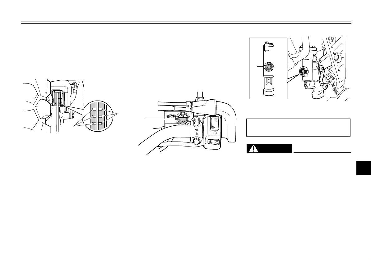
PERIODIC MAINTENANCE AND ADJUSTMENT
1
indicator groove has almost disappeared, have a Yamaha dealer replace
the brake pads as a set.
Rear brake pads
1
1. Wear indicator groove
Each rear brake pad is provided with
wear indicator grooves, which allow
you to check the brake pad wear without having to disassemble the brake.
To check the brake pad wear, check
the wear indicator grooves. If a brake
pad has worn to the point that the wear
indicator grooves have almost disappeared, have a Yamaha dealer replace
the brake pads as a set.
EAU36720
1
EAU22581
Checking the brake fluid level
Before riding, check that the brake fluid
is above the minimum level mark.
Check the brake fluid level with the top
of the reservoir level. Replenish the
brake fluid if necessary.
Front brake
1
1. Minimum level mark
7-22
Rear brake
1. Minimum level mark
Specified brake fluid:
DOT 4
EWA15990
WARNING
Improper maintenance can result in
loss of braking ability. Observe
these precautions:
●
Insufficient brake fluid may allow air to enter the brake system, reducing braking
performance.
●
Clean the filler cap before removing. Use only DOT 4 brake
fluid from a sealed container.
●
Use only the specified brake fluid; otherwise, the rubber seals
2
3
4
5
6
7
8
9
Page 62
PERIODIC MAINTENANCE AND ADJUSTMENT
may deteriorate, causing leakage.
●
Refill with the same type of
brake fluid. Adding a brake fluid
1
other than DOT 4 may result in a
harmful chemical reaction.
●
2
Be careful that water does not
enter the brake fluid reservoir
when refilling. Water will signifi-
3
cantly lower the boiling point of
the fluid and may result in vapor
4
5
lock.
NOTICE
Brake fluid may damage painted surfaces or plastic parts. Always clean
6
up spilled fluid immediately.
As the brake pads wear, it is normal for
7
the brake fluid level to gradually go
down. A low brake fluid level may indi-
8
cate worn brake pads and/or brake system leakage; therefore, be sure to
check the brake pads for wear and the
9
brake system for leakage. If the brake
fluid level goes down suddenly, have a
Yamaha dealer check the cause before
further riding.
ECA17640
EAU22731
Changing the brake fluid
Have a Yamaha dealer change the
brake fluid at the intervals specified in
the TIP after the periodic maintenance
and lubrication chart. In addition, have
the oil seals of the master cylinders and
calipers as well as the brake hoses replaced at the intervals listed below or
whenever they are damaged or leaking.
●
Oil seals: Replace every two
years.
●
Brake hoses: Replace every four
years.
EAU22760
Drive chain slack
The drive chain slack should be
checked before each ride and adjusted
if necessary.
EAU22774
To check the drive chain slack
1. Place the motorcycle on the sidestand.
TIP
When checking and adjusting the drive
chain slack, there should be no weight
on the motorcycle.
2. Shift the transmission into the neutral position.
3. Measure the drive chain slack as
shown.
Drive chain slack:
40.0–45.0 mm (1.57–1.77 in)
7-23
Page 63
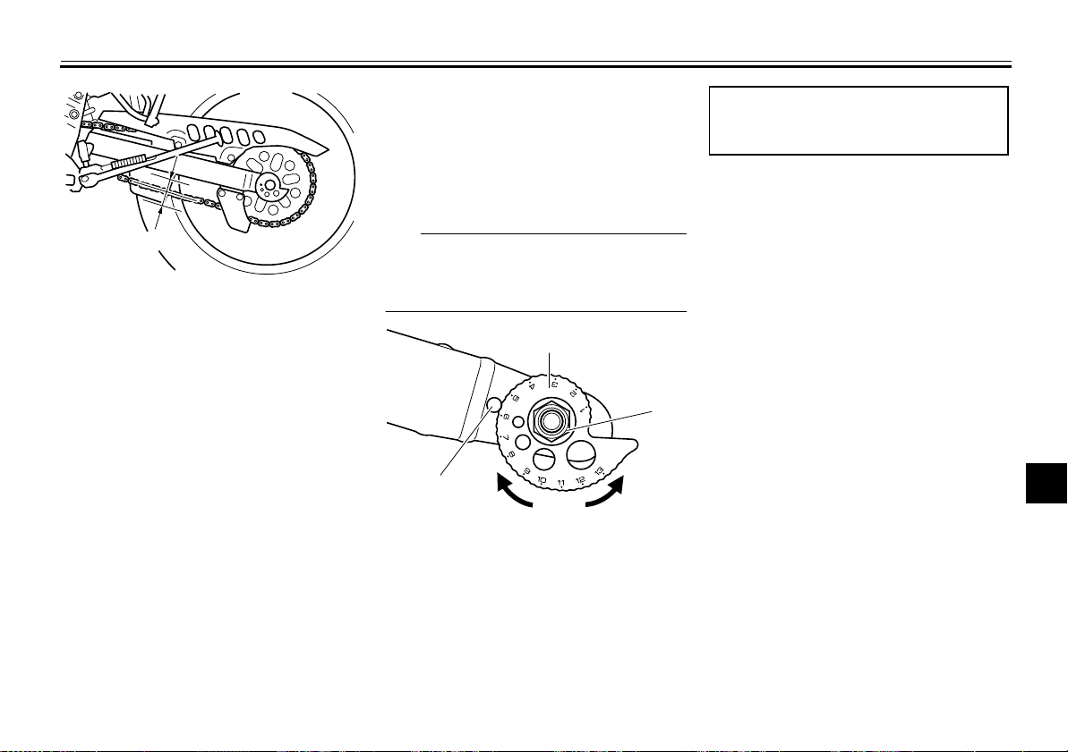
PERIODIC MAINTENANCE AND ADJUSTMENT
1
1. Drive chain slack
4. If the drive chain slack is incorrect,
adjust it as follows.
EAU22962
To adjust the drive chain slack
Consult a Yamaha dealer before adjusting the drive chain slack.
1. Loosen the axle nut.
2. To tighten the drive chain, turn the
drive chain slack adjusting plate on
each side of the swingarm in direction (a). To loosen the drive chain,
turn the adjusting plate on each
side of the swingarm in direction
(b), and then push the rear wheel
forward.
chain slack will overload the en-
NOTICE:
Improper drive
gine as well as other vital parts
of the motorcycle and can lead
to chain slippage or breakage.
To prevent this from occurring,
keep the drive chain slack within the specified limits.
[ECA10571]
TIP
Make sure that both adjusting plates
are in the same position for proper
wheel alignment.
2
3
(a)
1
1. Stopper
2. Drive chain slack adjusting plate
3. Axle nut
3. Tighten the axle nut to the specified torque.
(b)
Tightening torque:
Axle nut:
85 Nm (8.5 m·kgf, 61 ft·lbf)
4. Make sure that the drive chain pullers are in the same position, the
drive chain slack is correct, and
the drive chain moves smoothly.
2
3
4
5
6
7
8
9
7-24
Page 64
PERIODIC MAINTENANCE AND ADJUSTMENT
Cleaning and lubricating the drive chain
The drive chain must be cleaned and
1
lubricated at the intervals specified in
the periodic maintenance and lubrication chart, otherwise it will quickly wear
2
out, especially when riding in dusty or
wet areas. Service the drive chain as
3
follows.
NOTICE
4
The drive chain must be lubricated
after washing the motorcycle, riding
5
in the rain or riding in wet areas.
1. Clean the drive chain with kero-
6
7
8
9
sene and a small soft brush.
NOTICE:
To prevent damaging
the O-rings, do not clean the
drive chain with steam cleaners,
high-pressure washers or inappropriate solvents.
[ECA11121]
2. Wipe the drive chain dry.
3. Thoroughly lubricate the drive
chain with a special O-ring chain
lubricant.
NOTICE:
Do not use
engine oil or any other lubricants for the drive chain, as they
EAU23025
ECA10583
may contain substances that
could damage the O-rings.
[ECA11111]
Checking and lubricating the cables
The operation of all control cables and
the condition of the cables should be
checked before each ride, and the cables and cable ends should be lubricated if necessary. If a cable is damaged
or does not move smoothly, have a
Yamaha dealer check or replace it.
WARNING! Damage to the outer
housing of cables may result in internal rusting and cause interference with cable movement. Replace
damaged cables as soon as possible to prevent unsafe conditions.
[EWA10711]
Recommended lubricant:
Yamaha Chain and Cable Lube or
engine oil
EAU23095
7-25
Page 65
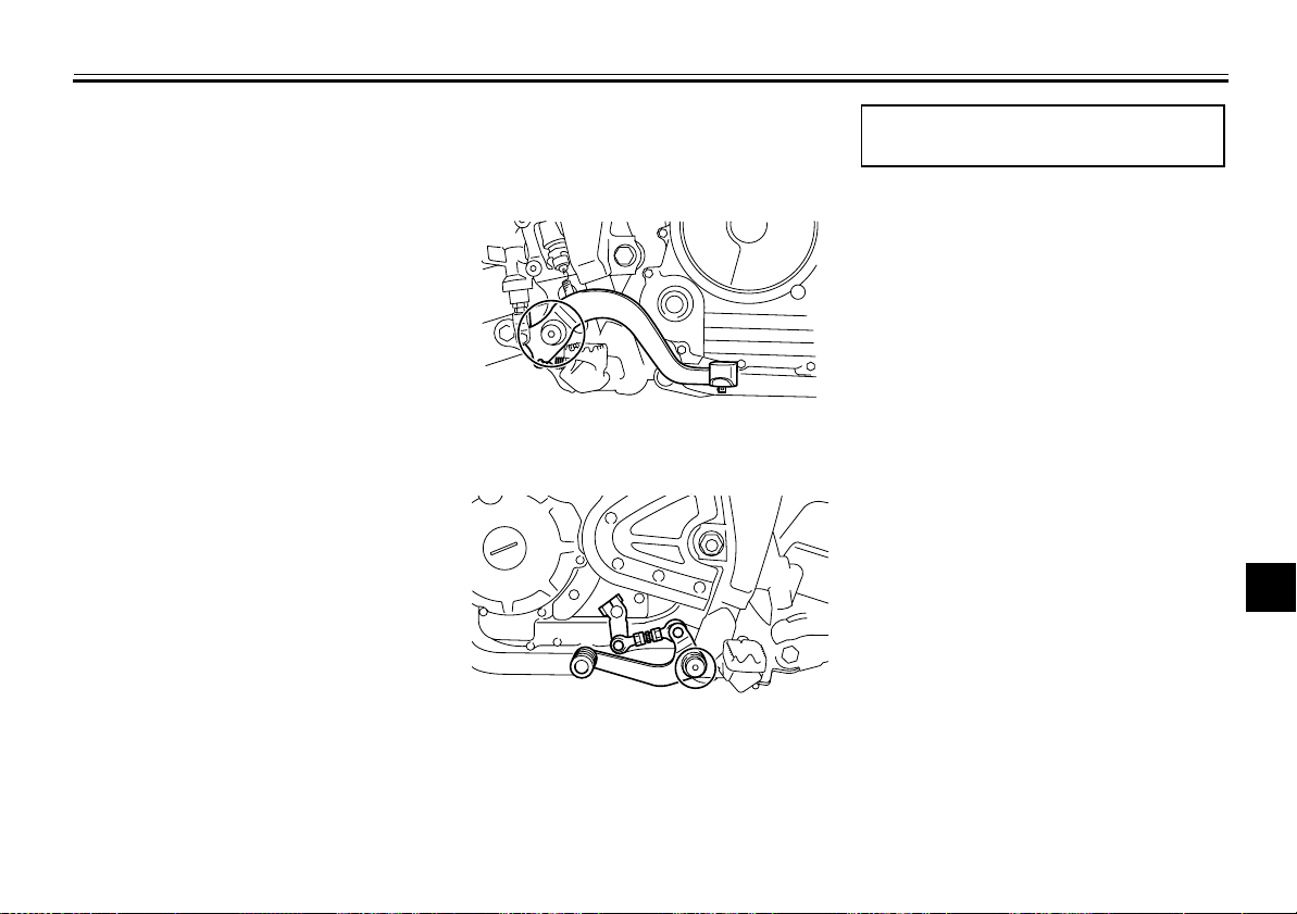
PERIODIC MAINTENANCE AND ADJUSTMENT
EAU23114
Checking and lubricating the throttle grip and cable
The operation of the throttle grip should
be checked before each ride. In addition, the cable should be lubricated by a
Yamaha dealer at the intervals specified in the periodic maintenance chart.
The throttle cable is equipped with a
rubber cover. Make sure that the cover
is securely installed. Even though the
cover is installed correctly, it does not
completely protect the cable from water
entry. Therefore, use care not to pour
water directly onto the cover or cable
when washing the vehicle. If the cable
or cover becomes dirty, wipe clean with
a moist cloth.
EAU44272
Checking and lubricating the brake and shift pedals
Brake pedal
Shift pedal
Recommended lubricant:
Lithium-soap-based grease
2
3
4
5
6
7
8
9
The operation of the brake and shift
pedals should be checked before each
ride, and the pedal pivots should be lubricated if necessary.
7-26
Page 66
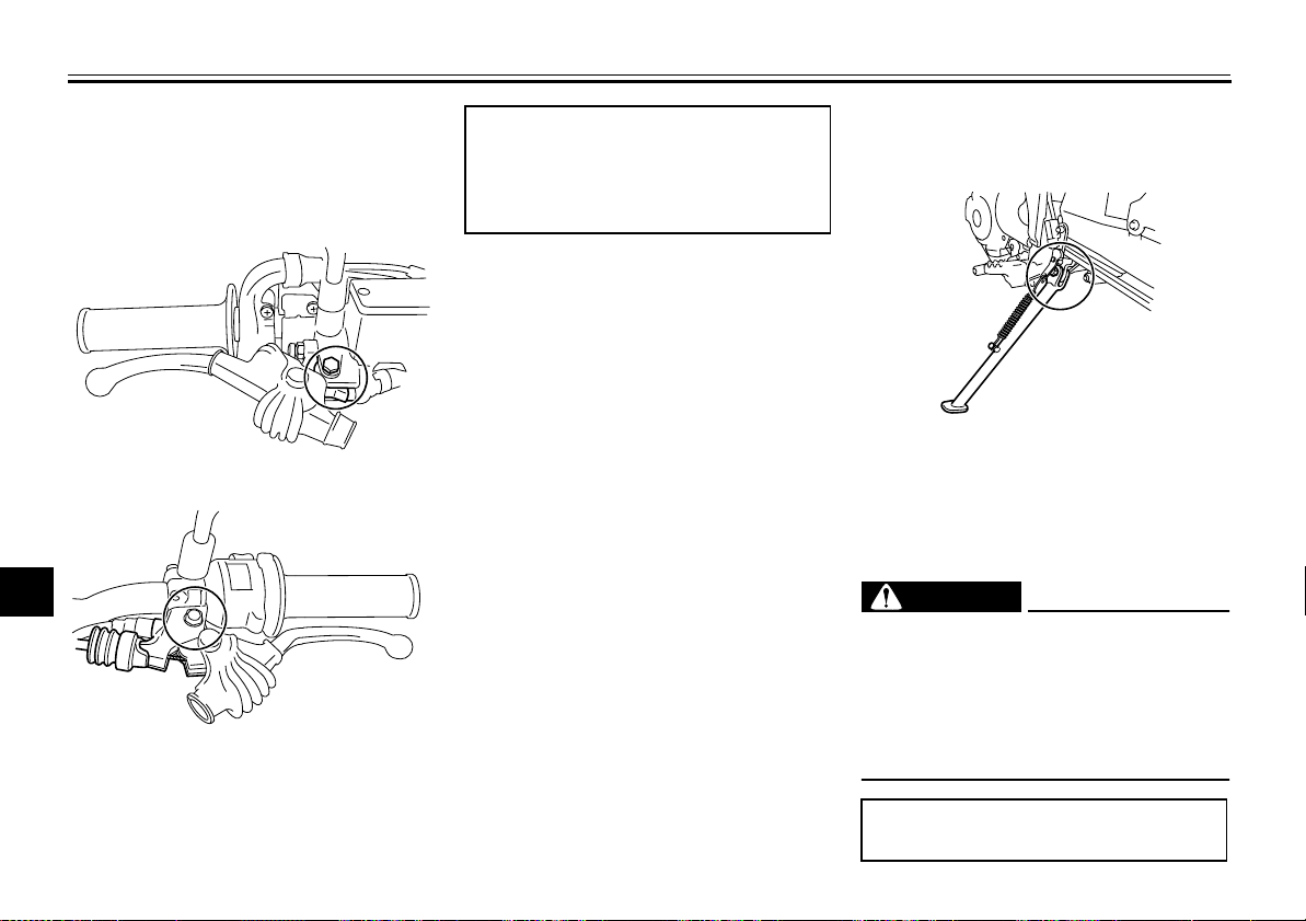
PERIODIC MAINTENANCE AND ADJUSTMENT
Checking and lubricating the brake and clutch levers
Brake lever
1
2
3
4
5
Clutch lever
6
7
8
9
The operation of the brake and clutch
levers should be checked before each
ride, and the lever pivots should be lubricated if necessary.
EAU23142
Recommended lubricants:
Brake lever:
Silicone grease
Clutch lever:
Lithium-soap-based grease
EAU23202
Checking and lubricating the sidestand
The operation of the sidestand should
be checked before each ride, and the
sidestand pivot and metal-to-metal
contact surfaces should be lubricated if
necessary.
EWA10731
WARNING
If the sidestand does not move up
and down smoothly, have a Yamaha
dealer check or repair it. Otherwise,
the sidestand could contact the
ground and distract the operator, resulting in a possible loss of control.
Recommended lubricant:
Lithium-soap-based grease
7-27
Page 67
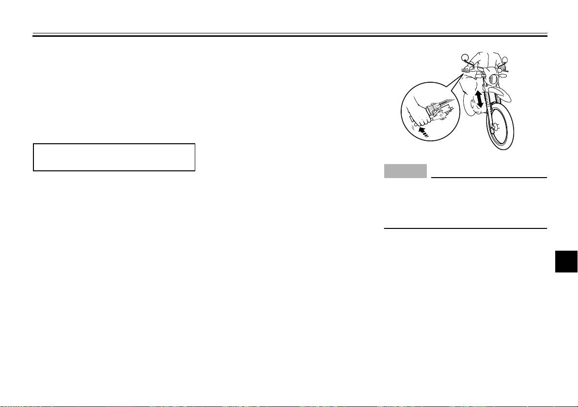
PERIODIC MAINTENANCE AND ADJUSTMENT
EAU23251
Lubricating the rear suspension
The pivoting points of the rear suspension must be lubricated by a Yamaha
dealer at the intervals specified in the
periodic maintenance and lubrication
chart.
Recommended lubricant:
Lithium-soap-based grease
EAU23272
Checking the front fork
The condition and operation of the front
fork must be checked as follows at the
intervals specified in the periodic maintenance and lubrication chart.
To check the condition
Check the inner tubes for scratches,
damage and excessive oil leakage.
To check the operation
1. Place the vehicle on a level surface and hold it in an upright position.
WARNING! To avoid injury,
securely support the vehicle so
there is no danger of it falling
over.
[EWA10751]
2. While applying the front brake,
push down hard on the handlebars
several times to check if the front
fork compresses and rebounds
smoothly.
ECA10590
NOTICE
If any damage is found or the front
fork does not operate smoothly,
have a Yamaha dealer check or repair it.
2
3
4
5
6
7
8
9
7-28
Page 68
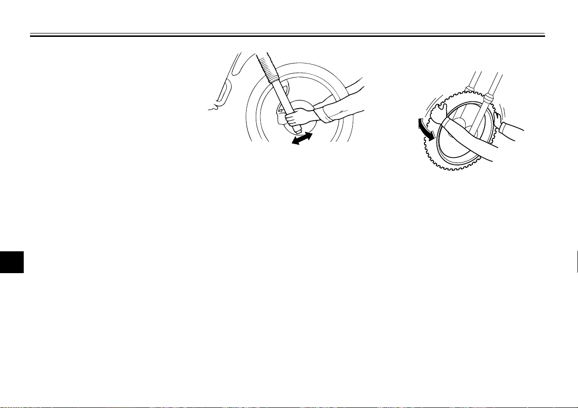
PERIODIC MAINTENANCE AND ADJUSTMENT
Checking the steering
Worn or loose steering bearings may
cause danger. Therefore, the operation
of the steering must be checked as fol-
1
lows at the intervals specified in the periodic maintenance and lubrication
2
chart.
1. Place a stand under the engine to
3
4
5
6
7
8
9
raise the front wheel off the
ground. (See page 7-34 for more
information.)
WARNING! To
avoid injury, securely support
the vehicle so there is no danger
of it falling over.
[EWA10751]
2. Hold the lower ends of the front
fork legs and try to move them forward and backward. If any free
play can be felt, have a Yamaha
dealer check or repair the steering.
EAU23283
EAU23291
Checking the wheel bearings
The front and rear wheel bearings must
be checked at the intervals specified in
the periodic maintenance and lubrication chart. If there is play in the wheel
hub or if the wheel does not turn
smoothly, have a Yamaha dealer check
the wheel bearings.
7-29
Page 69
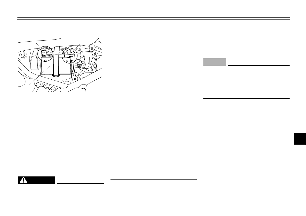
PERIODIC MAINTENANCE AND ADJUSTMENT
EAU23396
Battery
1
3
1. Negative battery lead (black)
2. Positive battery lead (red)
3. Battery
The battery is located behind panel C.
(See page 7-8.)
This model is equipped with a VRLA
(Valve Regulated Lead Acid) battery.
There is no need to check the electrolyte or to add distilled water. However,
the battery coupler needs to be
checked and, if necessary, securely
fastened.
WARNING
●
Electrolyte is poisonous and
dangerous since it contains sul-
2
EWA10760
furic acid, which causes severe
burns. Avoid any contact with
skin, eyes or clothing and always shield your eyes when
working near batteries. In case
of contact, administer the following FIRST AID.
• EXTERNAL: Flush with plenty
of water.
• INTERNAL: Drink large quantities of water or milk and immediately call a physician.
• EYES: Flush with water for 15
minutes and seek prompt
medical attention.
●
Batteries produce explosive hydrogen gas. Therefore, keep
sparks, flames, cigarettes, etc.,
away from the battery and provide sufficient ventilation when
charging it in an enclosed
space.
●
KEEP THIS AND ALL BATTERIES OUT OF THE REACH OF
CHILDREN.
To charge the battery
Have a Yamaha dealer charge the bat-
tery as soon as possible if it seems to
have discharged. Keep in mind that the
battery tends to discharge more quickly
if the vehicle is equipped with optional
electrical accessories.
ECA16521
NOTICE
To charge a VRLA (Valve Regulated
Lead Acid) battery, a special (constant-voltage) battery charger is required. Using a conventional battery
charger will damage the battery.
To store the battery
1. If the model will not be used for
more than one month, remove the
battery, fully charge it, and then
place it in a cool, dry place.
NOTICE:
When removing the
battery, be sure the key is
turned to “OFF” before disconnecting the coupler.
[ECA16322]
2. If the battery will be stored for more
than two months, check it at least
once a month and fully charge it if
necessary.
3. Fully charge the battery before installation.
NOTICE:
When install-
2
3
4
5
6
7
8
9
7-30
Page 70
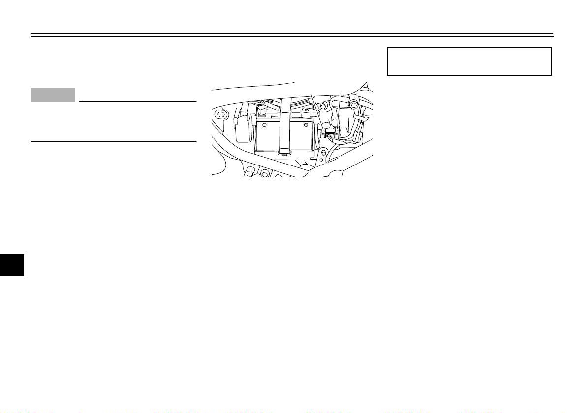
PERIODIC MAINTENANCE AND ADJUSTMENT
ing the battery, be sure the key
is turned to “OFF” before con-
[ECA16930]
1
necting the coupler.
NOTICE
Always keep the battery charged.
Storing a discharged battery can
2
cause permanent battery damage.
3
4
5
6
7
8
9
ECA16530
EAU23503
Replacing the fuse
1
1. Fuse
2. Spare fuse
The fuse holder is located behind panel
C. (See page 7-8.)
If the fuse is blown, replace it as follows.
1. Turn the key to “OFF” and turn off
all electrical circuits.
2. Remove the blown fuse, and then
install a new fuse of the specified
amperage.
use a fuse of a higher amperage
rating than recommended to
avoid causing extensive damage to the electrical system and
possibly a fire.
WARNING! Do not
[EWA15131]
2
Specified fuse:
20.0 A
3. Turn the key to “ON” and turn on
the electrical circuits to check if the
devices operate.
4. If the fuse immediately blows
again, have a Yamaha dealer
check the electrical system.
7-31
Page 71
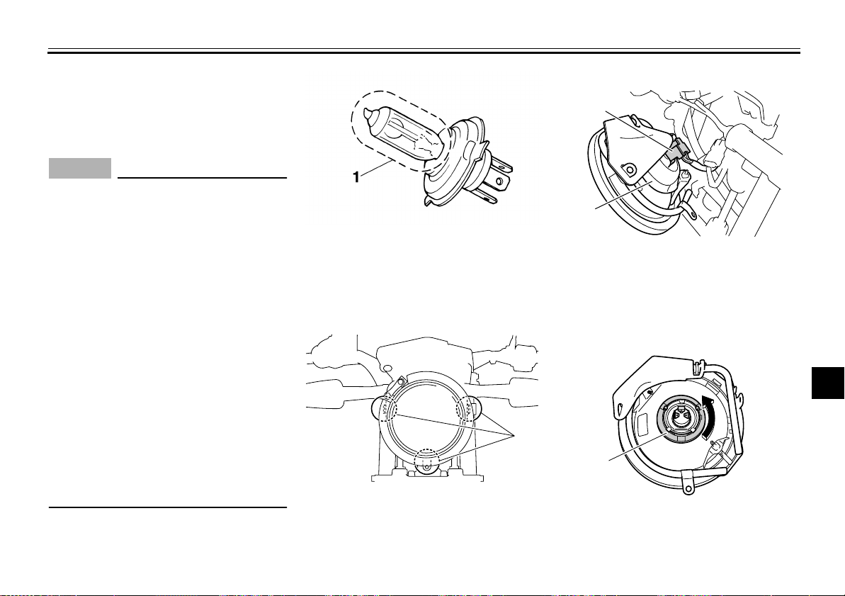
PERIODIC MAINTENANCE AND ADJUSTMENT
1
2
1
Replacing the headlight bulb
This model is equipped with a halogen
bulb headlight. If the headlight bulb
burns out, replace it as follows.
NOTICE
Take care not to damage the following parts:
Headlight bulb
●
Do not touch the glass part of
the headlight bulb to keep it free
from oil, otherwise the transparency of the glass, the luminosity
of the bulb, and the bulb life will
be adversely affected. Thoroughly clean off any dirt and fingerprints on the headlight bulb
using a cloth moistened with alcohol or thinner.
Headlight lens
●
Do not affix any type of tinted
film or stickers to the headlight
lens.
Do not use a headlight bulb of a
wattage higher than specified.
EAU23816
ECA10650
1. Do not touch the glass part of the bulb.
1. Remove cowling A. (See
page 7-8.)
2. Remove the headlight unit by removing the bolts.
1
1. Bolt
3. Disconnect the headlight coupler,
and then remove the headlight
7-32
bulb cover.
1. Headlight coupler
2. Headlight bulb cover
4. Remove the headlight bulb holder
by turning it counterclockwise, and
then remove the burnt-out bulb.
1. Headlight bulb holder
5. Place a new bulb into position, and
2
3
4
5
6
7
8
9
Page 72

PERIODIC MAINTENANCE AND ADJUSTMENT
1
then secure it with the bulb holder.
6. Install the bulb cover, and then
connect the coupler.
7. Place the headlight unit in the orig-
1
inal position, and then install the
bolts.
8. Install the cowling.
2
9. Have a Yamaha dealer adjust the
headlight beam if necessary.
3
4
5
6
7
8
9
EAU24133
Replacing the tail/brake light bulb
1. Remove the tail/brake light lens by
removing the screws.
1
2
1. Tail/brake light lens
2. Screw
2. Remove the burnt-out bulb by
pushing it in and turning it counterclockwise.
1. Tail/brake light bulb
3. Insert a new bulb into the socket,
push it in, and then turn it clockwise until it stops.
4. Install the lens by installing the
screws.
NOTICE:
Do not overtighten the screws, otherwise
the lens may break.
[ECA10681]
7-33
Page 73
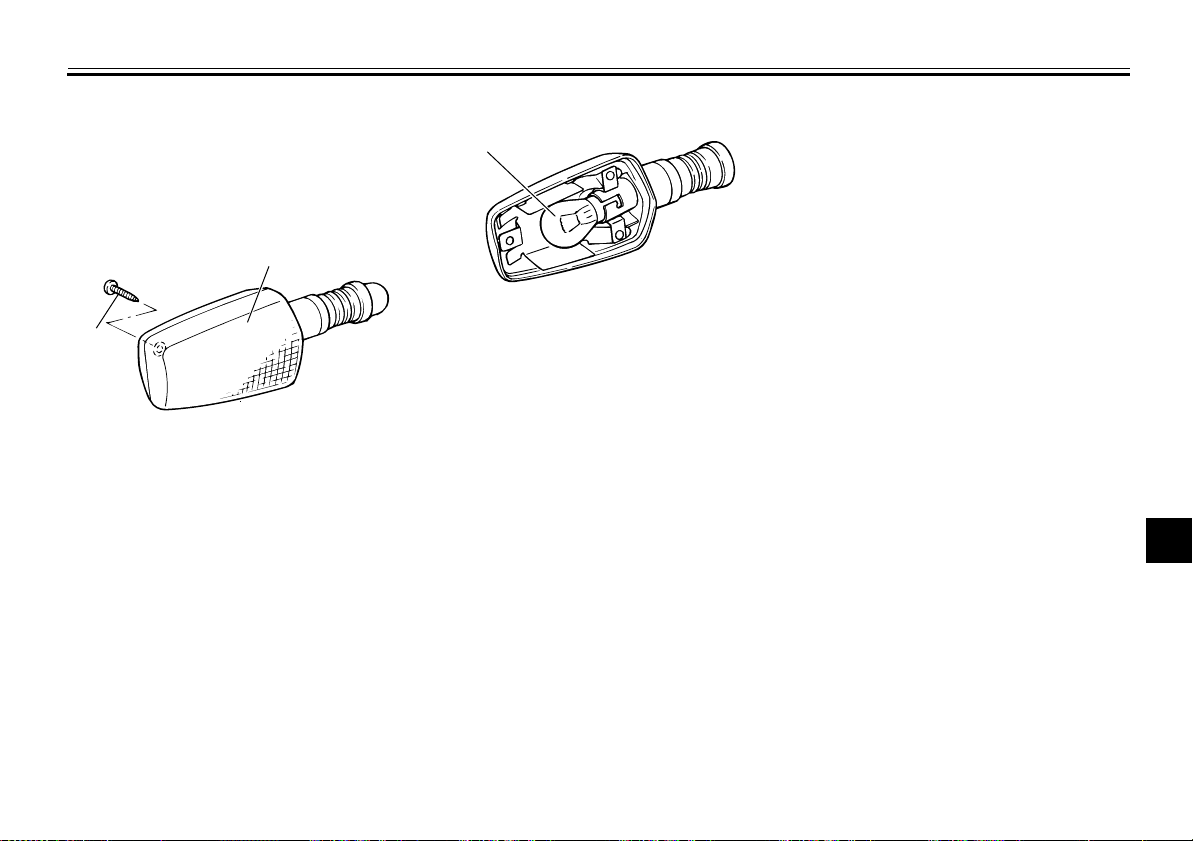
PERIODIC MAINTENANCE AND ADJUSTMENT
EAU24204
Replacing a turn signal light bulb
1. Remove the turn signal light lens
by removing the screw.
2
1
1. Screw
2. Turn signal light lens
2. Remove the burnt-out bulb by
pushing it in and turning it counterclockwise.
1
1. Turn signal light bulb
3. Insert a new bulb into the socket,
push it in, and then turn it clockwise until it stops.
4. Install the lens by installing the
screw.
tighten the screw, otherwise the
lens may break.
NOTICE:
7-34
Do not over-
[ECA11191]
EAU24350
Supporting the motorcycle
Since this model is not equipped with a
centerstand, follow these precautions
when removing the front and rear
wheel or performing other maintenance
requiring the motorcycle to stand upright. Check that the motorcycle is in a
stable and level position before starting
any maintenance. A strong wooden
box can be placed under the engine for
added stability.
To service the front wheel
1. Stabilize the rear of the motorcycle
by using a motorcycle stand or, if
an additional motorcycle stand is
not available, by placing a jack under the frame in front of the rear
wheel.
2. Raise the front wheel off the
ground by using a motorcycle
stand.
To service the rear wheel
Raise the rear wheel off the ground by
using a motorcycle stand or, if a motorcycle stand is not available, by placing
a jack either under each side of the
2
3
4
5
6
7
8
9
Page 74
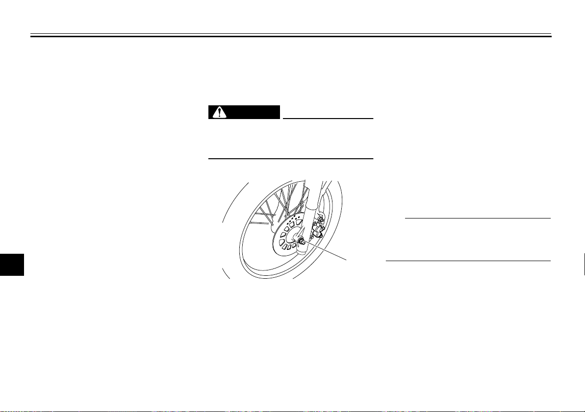
PERIODIC MAINTENANCE AND ADJUSTMENT
frame in front of the rear wheel or under
each side of the swingarm.
1
2
3
4
5
6
7
8
9
EAU24360
Front wheel
EAU51600
To remove the front wheel
EWA10821
WARNING
To avoid injury, securely support the
vehicle so there is no danger of it
falling over.
1. Loosen the axle nut.
1
1. Axle nut
2. Lift the front wheel off the ground
according to the procedure in the
previous section “Supporting the
motorcycle”.
3. Remove the axle nut and the
washer.
4. Pull the wheel axle out.
5. Remove the washer, spacers and
the wheel.
NOTICE:
Do not apply
the brake after the wheel has
been removed together with the
brake disc, otherwise the brake
pads will be forced shut.
[ECA11071]
EAU51611
To install the front wheel
1. Install the spacers into both sides
of the wheel hub.
2. Lift the wheel up between the fork
legs.
TIP
Make sure that there is enough space
between the brake pads before inserting the brake disc into the caliper.
3. Insert the wheel axle (together with
the right side washer) from the
right-hand side.
4. Install the left side washer and the
axle nut.
5. Lower the front wheel so that it is
on the ground.
6. Tighten the axle nut to the specified torque.
7-35
Page 75
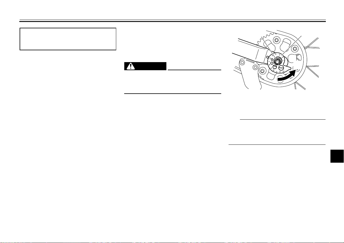
PERIODIC MAINTENANCE AND ADJUSTMENT
2
1
(a)
Tightening torque:
Axle nut:
85 Nm (8.5 m·kgf, 61 ft·lbf)
7. Push down hard on the handlebar
several times to check for proper
fork operation.
EAU25080
Rear wheel
EAU51621
To remove the rear wheel
EWA10821
WARNING
To avoid injury, securely support the
vehicle so there is no danger of it
falling over.
1. Loosen the axle nut.
2. Lift the rear wheel off the ground
according to the procedure on
page 7-34.
3. Turn the drive chain adjusting
plate on each side of the swingarm
fully in direction (a).
4. Push the wheel forward, and then
remove the drive chain from the
rear sprocket.
1. Axle nut
2. Drive chain adjusting plate
TIP
The drive chain does not need to be
disassembled in order to remove and
install the wheel.
5. Remove the axle nut, washer and
drive chain adjusting plate from the
left-hand side.
6. While supporting the brake caliper,
pull the wheel axle out together
with the drive chain adjusting plate
and washer from the right-hand
side.
2
3
4
5
6
7
8
9
7-36
Page 76
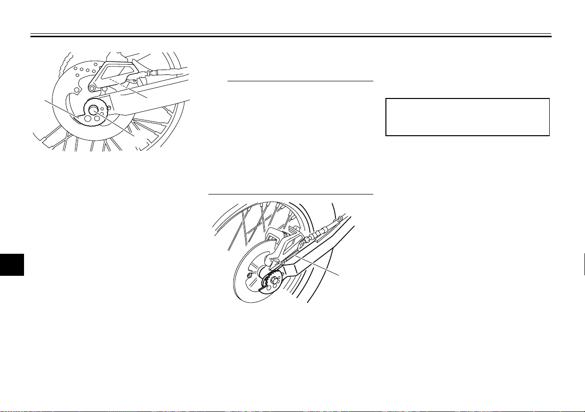
PERIODIC MAINTENANCE AND ADJUSTMENT
1
1
2
3
1. Drive chain adjusting plate
2. Wheel axle
4
3. Brake caliper
7. Remove the spacers and wheel by
5
pulling the wheel to the back.
6
NOTICE:
after the wheel has been re-
Do not apply the brake
moved together with the brake
7
disc, otherwise the brake pads
will be forced shut.
8
To install the rear wheel
9
1. Install the spacers into both sides
of the wheel hub.
2. Install the right side washer, both
drive chain adjusting plates, the
wheel and the brake caliper brack-
3
2
[ECA11071]
EAU51631
et by inserting the wheel axle from
the right-hand side.
TIP
Make sure that the drive chain ad-
●
justing plates are installed with the
punched sides facing to the outside and that the retainer on the
swingarm is inserted into the slot in
the brake caliper bracket.
Make sure that there is enough
●
space between the brake pads before installing the wheel.
1
1. Retainer
3. Install the drive chain onto the rear
sprocket, and then adjust the drive
chain slack. (See page 7-23.)
4. Install the left side washer and the
axle nut, and then lower the rear
wheel so that it is on the ground.
5. Tighten the axle nut to the specified torque.
Tightening torque:
Axle nut:
85 Nm (8.5 m·kgf, 61 ft·lbf)
7-37
Page 77
PERIODIC MAINTENANCE AND ADJUSTMENT
EAU25851
Troubleshooting
Although Yamaha motorcycles receive
a thorough inspection before shipment
from the factory, trouble may occur during operation. Any problem in the fuel,
compression, or ignition systems, for
example, can cause poor starting and
loss of power.
The following troubleshooting chart
represents a quick and easy procedure
for checking these vital systems yourself. However, should your motorcycle
require any repair, take it to a Yamaha
dealer, whose skilled technicians have
the necessary tools, experience, and
know-how to service the motorcycle
properly.
Use only genuine Yamaha replacement parts. Imitation parts may look like
Yamaha parts, but they are often inferior, have a shorter service life and can
lead to expensive repair bills.
EWA15141
WARNING
When checking the fuel system, do
not smoke, and make sure there are
no open flames or sparks in the area, including pilot lights from water
heaters or furnaces. Gasoline or
gasoline vapors can ignite or explode, causing severe injury or
property damage.
2
3
4
5
6
7
8
9
7-38
Page 78
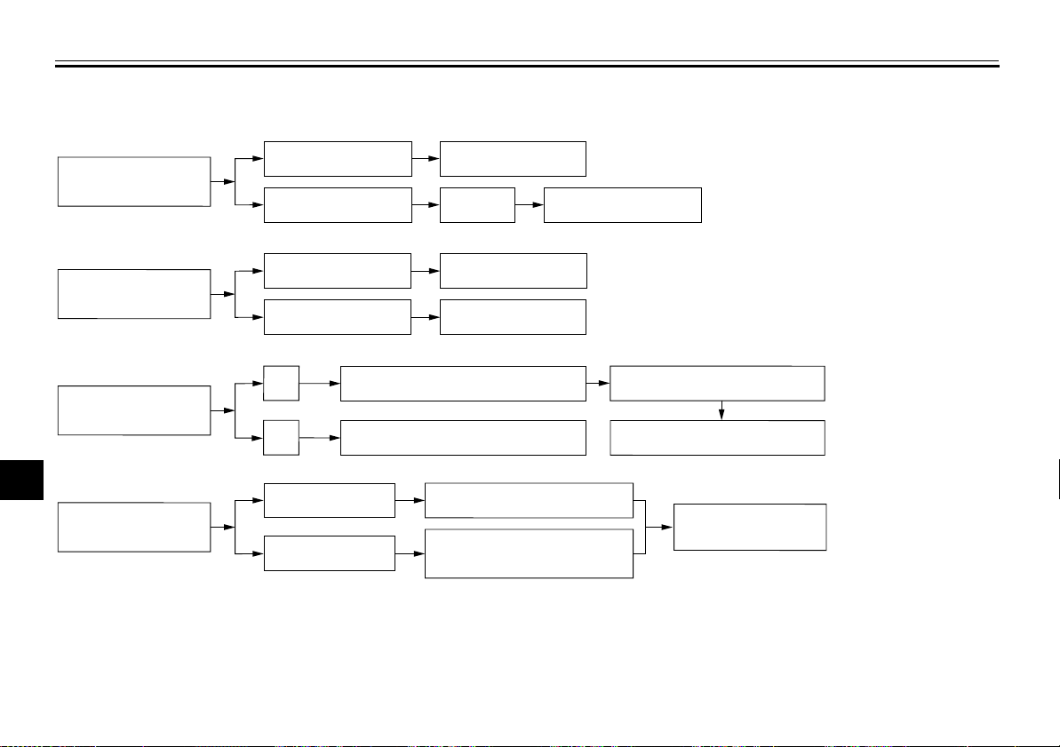
PERIODIC MAINTENANCE AND ADJUSTMENT
Troubleshooting chart
EAU25903
1. Fuel
Check the fuel level in
1
the fuel tank.
2
2. Compression
3
Operate the electric starter.
4
3. Ignition
5
Remove the spark plug
and check the electrodes.
6
7
4. Battery
Operate the electric starter.
8
9
There is enough fuel.
There is no fuel.
There is compression.
There is no compression.
Wet
Dry
The engine turns over
quickly.
The engine turns over
slowly.
Wipe off with a dry cloth and correct the
spark plug gap, or replace the spark plug.
Have a Yamaha dealer check the vehicle.
Check the compression.
Supply fuel.
Check the ignition.
Have a Yamaha dealer
check the vehicle.
The battery is good.
Check the battery lead connections,
and have a Yamaha dealer charge
the battery if necessary.
The engine does not start.
Check the compression.
Open the throttle halfway and operate
the electric starter.
The engine does not start.
Check the battery.
The engine does not start.
Have a Yamaha dealer
check the vehicle.
7-39
Page 79
MOTORCYCLE CARE AND STORAGE
EAU37833
Matte color caution
ECA15192
NOTICE
Some models are equipped with
matte colored finished parts. Be
sure to consult a Yamaha dealer for
advice on what products to use before cleaning the vehicle. Using a
brush, harsh chemical products or
cleaning compounds when cleaning
these parts will scratch or damage
their surface. Wax also should not
be applied to any matte colored finished parts.
EAU26004
Care
While the open design of a motorcycle
reveals the attractiveness of the technology, it also makes it more vulnerable. Rust and corrosion can develop
even if high-quality components are
used. A rusty exhaust pipe may go unnoticed on a car, however, it detracts
from the overall appearance of a motorcycle. Frequent and proper care does
not only comply with the terms of the
warranty, but it will also keep your motorcycle looking good, extend its life
and optimize its performance.
Before cleaning
1. Cover the muffler outlet with a
plastic bag after the engine has
cooled down.
2. Make sure that all caps and covers
as well as all electrical couplers
and connectors, including the
spark plug cap, are tightly installed.
3. Remove extremely stubborn dirt,
like oil burnt onto the crankcase,
with a degreasing agent and a
brush, but never apply such prod-
8-1
ucts onto seals, gaskets, sprockets, the drive chain and wheel
axles. Always rinse the dirt and degreaser off with water.
Cleaning
NOTICE
Avoid using strong acidic wheel
●
cleaners, especially on spoked
wheels. If such products are
used on hard-to-remove dirt, do
not leave the cleaner on the affected area any longer than instructed. Also, thoroughly rinse
the area off with water, immediately dry it, and then apply a corrosion protection spray.
Improper cleaning can damage
●
plastic parts (such as cowlings,
panels, windshields, headlight
lenses, meter lenses, etc.) and
the mufflers. Use only a soft,
clean cloth or sponge with water to clean plastic. However, if
the plastic parts cannot be thoroughly cleaned with water, diluted mild detergent with water
may be used. Be sure to rinse
ECA10772
2
3
4
5
6
7
8
9
Page 80
MOTORCYCLE CARE AND STORAGE
off any detergent residue using
plenty of water, as it is harmful
to plastic parts.
●
Do not use any harsh chemical
1
products on plastic parts. Be
sure to avoid using cloths or
2
sponges which have been in
contact with strong or abrasive
cleaning products, solvent or
3
thinner, fuel (gasoline), rust removers or inhibitors, brake flu-
4
5
id, antifreeze or electrolyte.
●
Do not use high-pressure washers or steam-jet cleaners since
they cause water seepage and
deterioration in the following ar-
6
eas: seals (of wheel and swingarm bearings, fork and brakes),
7
electric components (couplers,
connectors, instruments,
8
9
switches and lights), breather
hoses and vents.
●
For motorcycles equipped with
a windshield: Do not use strong
cleaners or hard sponges as
they will cause dulling or
scratching. Some cleaning compounds for plastic may leave
scratches on the windshield.
Test the product on a small hidden part of the windshield to
make sure that it does not leave
any marks. If the windshield is
scratched, use a quality plastic
polishing compound after
washing.
After normal use
Remove dirt with warm water, a mild
detergent, and a soft, clean sponge,
and then rinse thoroughly with clean
water. Use a toothbrush or bottlebrush
for hard-to-reach areas. Stubborn dirt
and insects will come off more easily if
the area is covered with a wet cloth for
a few minutes before cleaning.
After riding in the rain, near the sea or
on salt-sprayed roads
Since sea salt or salt sprayed on roads
during winter are extremely corrosive in
combination with water, carry out the
following steps after each ride in the
rain, near the sea or on salt-sprayed
roads.
TIP
Salt sprayed on roads in the winter may
remain well into spring.
1. Clean the motorcycle with cold water and a mild detergent, after the
engine has cooled down.
NOTICE:
Do not use warm water
since it increases the corrosive
action of the salt.
[ECA10791]
2. Apply a corrosion protection spray
on all metal, including chrome- and
nickel-plated, surfaces to prevent
corrosion.
After cleaning
1. Dry the motorcycle with a chamois
or an absorbing cloth.
2. Immediately dry the drive chain
and lubricate it to prevent it from
rusting.
3. Use a chrome polish to shine
chrome, aluminum and stainless-steel parts, including the exhaust system. (Even the thermally
induced discoloring of stainless-steel exhaust systems can be
removed through polishing.)
4. To prevent corrosion, it is recom-
8-2
Page 81

MOTORCYCLE CARE AND STORAGE
mended to apply a corrosion protection spray on all metal,
including chrome- and nickel-plated, surfaces.
5. Use spray oil as a universal cleaner to remove any remaining dirt.
6. Touch up minor paint damage
caused by stones, etc.
7. Wax all painted surfaces.
8. Let the motorcycle dry completely
before storing or covering it.
EWA11131
WARNING
Contaminants on the brakes or tires
can cause loss of control.
Make sure that there is no oil or
●
wax on the brakes or tires.
If necessary, clean the brake
●
discs and brake linings with a
regular brake disc cleaner or acetone, and wash the tires with
warm water and a mild detergent. Before riding at higher
speeds, test the motorcycle’s
braking performance and cornering behavior.
NOTICE
Apply spray oil and wax spar-
●
ingly and make sure to wipe off
any excess.
Never apply oil or wax to any
●
rubber and plastic parts, but
treat them with a suitable care
product.
Avoid using abrasive polishing
●
compounds as they will wear
away the paint.
TIP
●
Consult a Yamaha dealer for advice on what products to use.
●
Washing, rainy weather or humid
climates can cause the headlight
lens to fog. Turning the headlight
on for a short period of time will
help remove the moisture from the
lens.
ECA10800
EAU26152
Storage
Short-term
Always store your motorcycle in a cool,
dry place and, if necessary, protect it
against dust with a porous cover. Be
sure the engine and the exhaust system are cool before covering the motorcycle.
NOTICE
Storing the motorcycle in a
●
poorly ventilated room or covering it with a tarp, while it is still
wet, will allow water and humidity to seep in and cause rust.
To prevent corrosion, avoid
●
damp cellars, stables (because
of the presence of ammonia)
and areas where strong chemicals are stored.
Long-term
Before storing your motorcycle for several months:
1. Follow all the instructions in the
“Care” section of this chapter.
ECA10810
2
3
4
5
6
7
8
9
8-3
Page 82
MOTORCYCLE CARE AND STORAGE
2. For motorcycles equipped with a
fuel cock that has an “OFF” position: Turn the fuel cock lever to
“OFF”.
1
3. Drain the carburetor float chamber
by loosening the drain bolt; this will
2
prevent fuel deposits from building
up. Pour the drained fuel into the
fuel tank.
3
4. Fill up the fuel tank and add fuel
stabilizer (if available) to prevent
4
the fuel tank from rusting and the
fuel from deteriorating.
5. Perform the following steps to pro-
5
tect the cylinder, piston rings, etc.
from corrosion.
6
a. Remove the spark plug cap
and spark plug.
7
b. Pour a teaspoonful of engine oil
into the spark plug bore.
8
c. Install the spark plug cap onto
the spark plug, and then place
the spark plug on the cylinder
9
head so that the electrodes are
grounded. (This will limit sparking during the next step.)
d. Turn the engine over several
times with the starter. (This will
coat the cylinder wall with oil.)
WARNING! To prevent damage or injury from sparking,
make sure to ground the
spark plug electrodes while
turning the engine
[EWA10951]
over.
e. Remove the spark plug cap
from the spark plug, and then
install the spark plug and the
spark plug cap.
6. Lubricate all control cables and the
pivoting points of all levers and
pedals as well as of the sidestand/
centerstand.
7. Check and, if necessary, correct
the tire air pressure, and then lift
the motorcycle so that both of its
wheels are off the ground. Alternatively, turn the wheels a little every
month in order to prevent the tires
from becoming degraded in one
spot.
8. Cover the muffler outlet with a
plastic bag to prevent moisture
from entering it.
9. Remove the battery and fully
charge it. Store it in a cool, dry
place and charge it once a month.
Do not store the battery in an excessively cold or warm place [less
than 0 °C (30 °F) or more than 30
°C (90 °F)]. For more information
on storing the battery, see page
7-30.
TIP
Make any necessary repairs before
storing the motorcycle.
8-4
Page 83
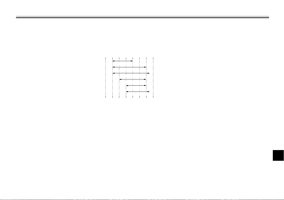
SPECIFICATIONS
Dimensions:
Overall length:
2160 mm (85.0 in)
Overall width:
805 mm (31.7 in)
Overall height:
1160 mm (45.7 in)
Seat height:
810 mm (31.9 in)
Wheelbase:
1360 mm (53.5 in)
Ground clearance:
285 mm (11.22 in)
Minimum turning radius:
1900 mm (74.8 in)
Weight:
Curb weight:
131 kg (289 lb)
Engine:
Engine type:
Air cooled 4-stroke, SOHC
Cylinder arrangement:
Single cylinder
Displacement:
Bore × stroke:
Compression ratio:
Starting system:
Lubrication system:
3
249 cm
74.0 × 58.0 mm (2.91 × 2.28 in)
9.50 : 1
Electric starter
Wet sump
EAU50912
Engine oil:
Recommended brand:
YAMALUBE
Type:
SAE 10W-30, 10W-40, 10W-50, 15W-40,
20W-40 or 20W-50
10 30 50 70 90 1100 130 ˚F
SAE 10W-30
SAE 10W-40
SAE 10W-50
SAE 15W-40
SAE 20W-40
SAE 20W-50
–20 –10 0
Recommended engine oil grade:
API service SG type or higher, JASO standard MA
Engine oil quantity:
Without oil filter element replacement:
With oil filter element replacement:
20 30 40 50 ˚C
10
1.20 L (1.27 US qt, 1.06 Imp.qt)
1.30 L (1.37 US qt, 1.14 Imp.qt)
Air filter:
Air filter element:
Oil-coated paper element
Fuel:
Recommended fuel:
Unleaded gasoline only
Fuel tank capacity:
10.0 L (2.64 US gal, 2.20 Imp.gal)
Fuel reserve amount:
1.9 L (0.50 US gal, 0.42 Imp.gal)
Carburetor:
Type × quantity:
MV33 x 1
Spark plug(s):
Manufacturer/model:
NGK/DR7EA
Spark plug gap:
0.6–0.7 mm (0.024–0.028 in)
Clutch:
Clutch type:
Wet, multiple-disc
Transmission:
Primary reduction ratio:
3.083 (74/24)
Final drive:
Chain
Secondary reduction ratio:
3.200 (48/15)
Transmission type:
Constant mesh 5-speed
Operation:
Left foot operation
Gear ratio:
1st:
2.846 (37/13)
2nd:
1.812 (29/16)
3rd:
1.318 (29/22)
4th:
1.035 (29/28)
2
3
4
5
6
7
8
9
9-1
Page 84
SPECIFICATIONS
5th:
0.821 (23/28)
Chassis:
Frame type:
1
2
Semi double cradle
Caster angle:
26.42 °
Trail:
106 mm (4.2 in)
Front tire:
3
4
Size:
2.75-21 45P
Manufacturer/model:
BRIDGESTONE/TW-301
Rear tire:
5
6
7
8
Size:
120/80-18M/C 62P
Manufacturer/model:
BRIDGESTONE/TW-302
Loading:
Maximum load:
151 kg (333 lb)
* (Total weight of rider, passenger, cargo
and accessories)
Tire air pressure (measured on cold
tires):
9
Loading condition:
0–90 kg (0–198 lb)
Front:
125 kPa (1.25 kgf/cm2, 18 psi)
Rear:
150 kPa (1.50 kgf/cm2, 22 psi)
Loading condition:
90–160 kg (198–353 lb)
Front:
150 kPa (1.50 kgf/cm
Rear:
175 kPa (1.75 kgf/cm2, 25 psi)
Front wheel:
Wheel type:
Spoke wheel
Rim size:
21x1.60
Rear wheel:
Wheel type:
Spoke wheel
Rim size:
18M/C x MT2.15
Front brake:
Type:
Single disc brake
Operation:
Right hand operation
Specified brake fluid:
DOT 4
Rear brake:
Type:
Single disc brake
Operation:
Right foot operation
Specified brake fluid:
DOT 4
Front suspension:
Type:
Telescopic fork
2
, 22 psi)
Spring/shock absorber type:
Coil spring/oil damper
Wheel travel:
225.0 mm (8.86 in)
Rear suspension:
Type:
Swingarm (link suspension)
Spring/shock absorber type:
Coil spring/gas-oil damper
Wheel travel:
180.0 mm (7.09 in)
Electrical system:
Ignition system:
DC CDI
Charging system:
AC magneto
Battery:
Model:
YTZ7S
Voltage, capacity:
12 V, 6.0 Ah
Headlight:
Bulb type:
Halogen bulb
Bulb voltage, wattage
Headlight:
12 V, 60 W/55 W × 1
Tail/brake light:
12 V, 5.0 W/21.0 W × 1
Front turn signal light:
12 V, 21.0 W × 2
Rear turn signal light:
12 V, 21.0 W × 2
×××× quantity:
9-2
Page 85
Neutral indicator light:
LED
High beam indicator light:
LED
Turn signal indicator light:
LED
Fuse:
Main fuse:
20.0 A
SPECIFICATIONS
2
3
4
5
6
7
8
9-3
9
Page 86
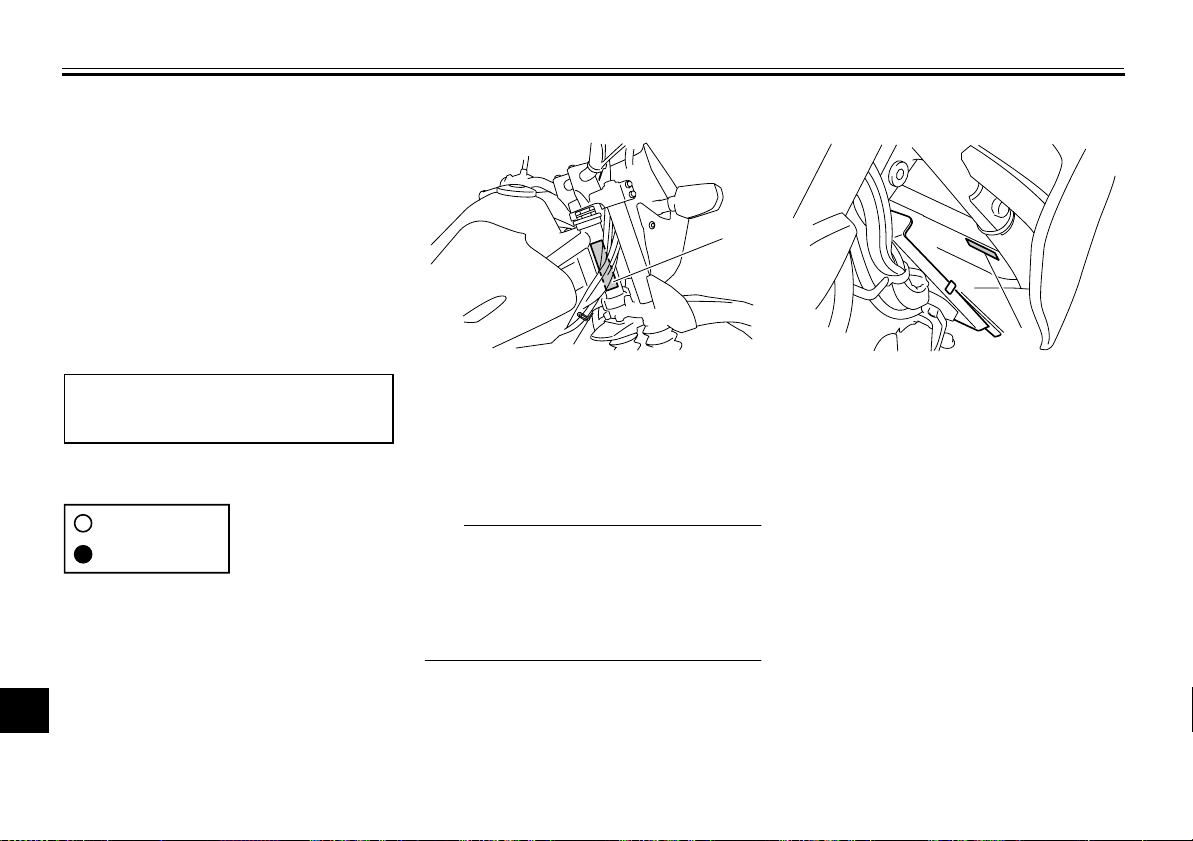
CONSUMER INFORMATION
1
Identification numbers
Record the vehicle identification number and model label information in the
spaces provided below for assistance
1
when ordering spare parts from a
Yamaha dealer or for reference in case
2
the vehicle is stolen.
3
VEHICLE IDENTIFICATION
NUMBER:
4
5
MODEL LABEL INFORMATION:
6
7
8
9
EAU48612
EAU26400
Vehicle identification number
1
1. Vehicle identification number
The vehicle identification number is
stamped into the steering head pipe.
Record this number in the space provided.
TIP
The vehicle identification number is
used to identify your motorcycle and
may be used to register your motorcycle with the licensing authority in your
area.
EAU36980
Model label
1. Model label
The model label is affixed to the frame
behind panel A. (See page 7-8.)
Record the information on this label in
the space provided. This information
will be needed when ordering spare
parts from a Yamaha dealer.
10
10-1
Page 87
EAU26570
Motorcycle noise regulation (for Australia)
TAMPERING WITH NOISE CONTROL SYSTEM PROHIBITED:
Owners are warned that the law may
prohibit:
●
The removal or rendering inoperative by any person other than for
purposes of maintenance, repair
or replacement, of any device or
element of design incorporated
into any new vehicle for the purpose of noise control prior to its
sale or delivery to the ultimate purchaser or while it is in use; and
●
The use of the vehicle after such
device or element of design has
been removed or rendered inoperative by any person.
CONSUMER INFORMATION
2
3
4
5
6
7
8
10-2
9
10
Page 88
INDEX
A
Air filter element and check hose,
replacing and cleaning.......................... 7-14
B
Battery..................................................... 7-30
Brake and clutch levers, checking and
lubricating ............................................. 7-27
Brake and shift pedals, checking and
lubricating ............................................. 7-26
Brake fluid, changing .............................. 7-23
Brake fluid level, checking ...................... 7-22
Brake lever................................................ 4-6
Brake lever free play, adjusting............... 7-20
Brake light switches ................................ 7-21
Brake pedal............................................... 4-6
C
Cables, checking and lubricating ............ 7-25
Carburetor, adjusting .............................. 7-16
Care .......................................................... 8-1
Clutch lever ............................................... 4-5
Clutch lever free play, adjusting.............. 7-20
Cowling and panels, removing and
installing.................................................. 7-8
D
Dimmer switch .......................................... 4-4
Drive chain, cleaning and lubricating ...... 7-25
Drive chain slack..................................... 7-23
E
Engine break-in......................................... 6-3
Engine idling speed................................. 7-16
Engine oil and oil filter element ............... 7-12
Engine, starting a warm ............................ 6-2
Engine stop switch .................................... 4-5
F
Front and rear brake pads, checking.......7-21
Front fork, checking .................................7-28
Fuel............................................................4-7
Fuel cock ...................................................4-8
Fuel consumption, tips for reducing...........6-3
Fuel tank cap .............................................4-6
Fuse, replacing ........................................7-31
H
Handlebar switches ...................................4-4
Headlight bulb, replacing .........................7-32
Helmet holder ..........................................4-10
High beam indicator light ...........................4-2
Horn switch................................................4-5
I
Identification numbers .............................10-1
Ignition circuit cut-off system ...................4-13
Indicator lights ...........................................4-2
L
Labels, location..........................................1-1
M
Main switch/steering lock...........................4-1
Maintenance and lubrication, periodic .......7-4
Maintenance, emission control system......7-3
Matte color, caution ...................................8-1
Model label ..............................................10-1
Multi-function display .................................4-3
N
Neutral indicator light.................................4-2
Noise regulation (for Australia) ................10-2
P
Parking ......................................................6-4
Part locations.............................................3-1
R
Rear suspension, lubricating...................7-28
S
Safety information .....................................2-1
Seat.........................................................4-10
Shifting ......................................................6-2
Shift pedal .................................................4-5
Shock absorber assembly, adjusting ...... 4-11
Sidestand ................................................4-12
Sidestand, checking and lubricating........ 7-27
Spark plug, checking...............................7-10
Specifications ............................................ 9-1
Starter (choke) knob.................................. 4-9
Starting and warming up a cold engine.....6-1
Start switch................................................ 4-5
Steering, checking................................... 7-29
Storage...................................................... 8-3
Supporting the motorcycle ...................... 7-34
T
Tail/brake light bulb, replacing ................ 7-33
Throttle grip and cable, checking and
lubricating.............................................. 7-26
Throttle grip free play, checking .............. 7-17
Tires ........................................................7-17
Tool kit....................................................... 7-2
Troubleshooting ...................................... 7-38
Troubleshooting chart ............................. 7-39
Turn signal indicator light ..........................4-2
Turn signal light bulb, replacing .............. 7-34
Turn signal switch ..................................... 4-4
V
Valve clearance....................................... 7-17
Vehicle identification number ..................10-1
Page 89
W
Wheel bearings, checking .......................7-29
Wheel (front)............................................7-35
Wheel (rear).............................................7-36
Wheels.....................................................7-19
INDEX
Page 90

Page 91

Page 92

PRINTED ON RECYCLED PAPER
PRINTED IN JAPAN
2011.08–0.1×1 !
(E)
 Loading...