


XV17PCV(C)
Table of contents
 Loading...
5PX-28199-14
XV17PCV(C)
XV17PCMV(C)
OWNER’S MANUAL
LIT-11626-19-46
EAU10041

INTRODUCTION
EAU10080
Congratulations on your purchase of the Yamaha XV17PCV(C)/XV17PCMV(C). This model is the result of Yamaha’s vast
experience in the production of fine sporting, touring, and pacesetting racing machines. It represents the high degree of
craftsmanship and reliability that have made Yamaha a leader in these fields.
This manual will give you an understanding of the operation, inspection, and basic maintenance of this motorcycle. If you
have any questions concerning the operation or maintenance of your motorcycle, please consult a Yamaha dealer.
The design and manufacture of this Yamaha motorcycle fully comply with the emissions standards for clean air applicable at
the date of manufacture. Yamaha has met these standards without reducing the performance or economy of operation of the
motorcycle. To maintain these high standards, it is important that you and your Yamaha dealer pay close attention to the
recommended maintenance schedules and operating instructions contained within this manual.
IMPORTANT MANUAL INFORMATION
EAU10131
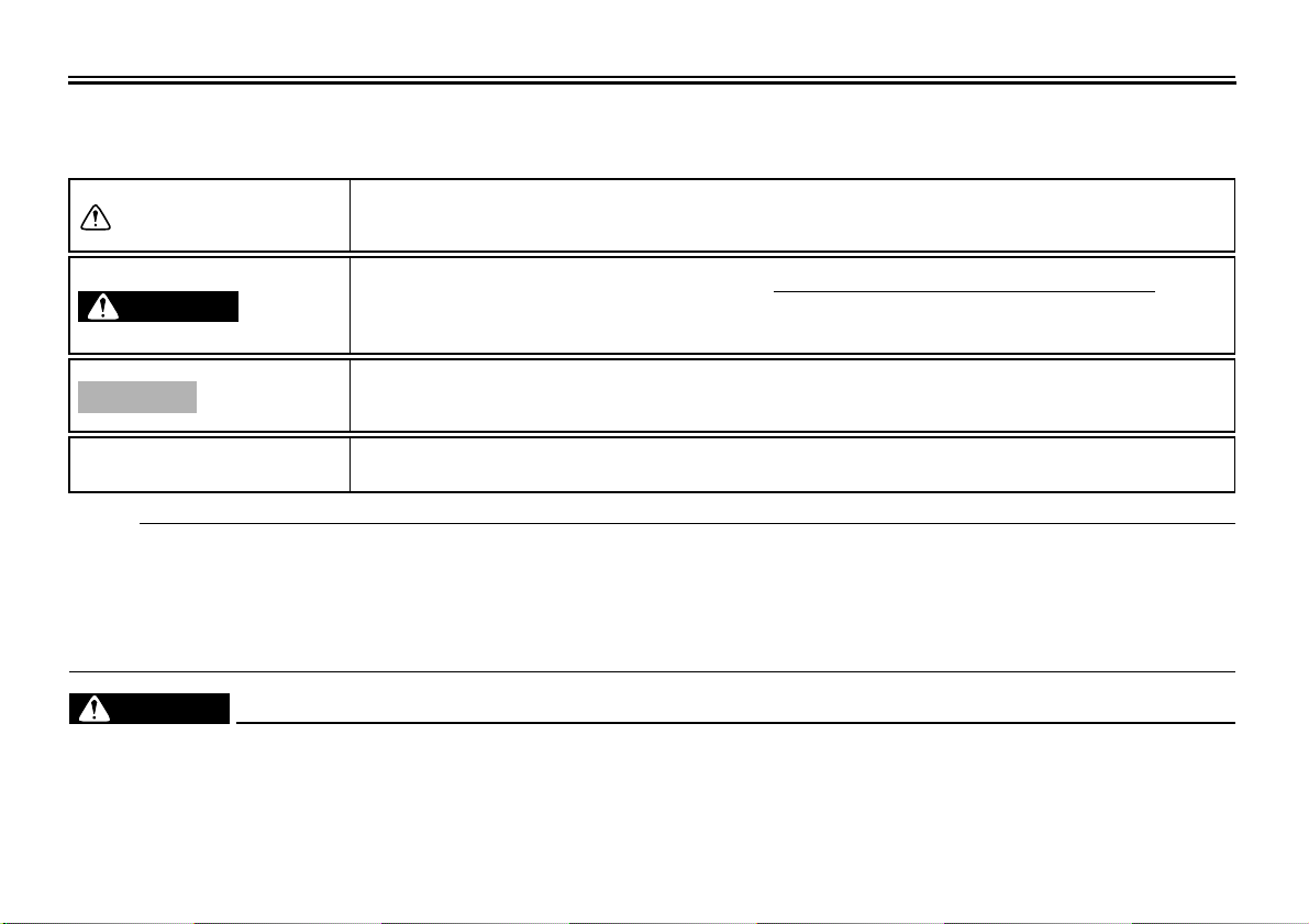
Particularly important information is distinguished in this manual by the following notations:
NOTE:
● This manual should be considered a permanent part of this motorcycle and should remain with it even if the motorcycle
is subsequently sold.
● Yamaha continually seeks advancements in product design and quality. Therefore, while this manual contains the most
current product information available at the time of printing, there may be minor discrepancies between your motorcycle
and this manual. If you have any questions concerning this manual, please consult your Yamaha dealer.
WARNING
EWA10010
PLEASE READ THIS MANUAL AND THE “YOU AND YOUR MOTORCYCLE: RIDING TIPS” BOOKLET CAREFULLY
AND COMPLETELY BEFORE OPERATING THIS MOTORCYCLE. DO NOT ATTEMPT TO OPERATE THIS MOTOR-
CYCLE UNTIL YOU HAVE ATTAINED ADEQUATE KNOWLEDGE OF ITS CONTROLS AND OPERATING FEATURES
The Safety Alert Symbol means ATTENTION! BECOME ALERT! YOUR SAFETY IS
INVOLVED!
Failure to follow WARNING instructions could result in severe injury or death
to the
motorcycle operator, a bystander or a person inspecting or repairing the motor-
cycle.
A CAUTION indicates special precautions that must be taken to avoid damage to
the motorcycle.
A NOTE provides key information to make procedures easier or clearer.
WARNING
CAUTION:
NOTE:

IMPORTANT MANUAL INFORMATION
AND UNTIL YOU HAVE BEEN TRAINED IN SAFE AND PROPER RIDING TECHNIQUES. REGULAR INSPECTIONS
AND CAREFUL MAINTENANCE, ALONG WITH GOOD RIDING SKILLS, WILL ENSURE THAT YOU SAFELY ENJOY
THE CAPABILITIES AND THE RELIABILITY OF THIS MOTORCYCLE.
*Product and specifications are subject to change without notice.
IMPORTANT MANUAL INFORMATION
EAU10192
XV17PCV(C)/XV17PCMV(C)
OWNER’S MANUAL
©2005 by Yamaha Motor Corporation, U.S.A.
1st edition, May 2005
All rights reserved.
Any reprinting or unauthorized use
without the written permission of
Yamaha Motor Corporation, U.S.A.
is expressly prohibited.
Printed in Japan.
P/N LIT-11626-19-46
AFFIX DEALER
LABEL HERE

TABLE OF CONTENTS
SAFETY INFORMATION ..................1-1
Location of important labels ...........1-5
DESCRIPTION ..................................2-1
Left view ..........................................2-1
Right view........................................2-2
Controls and instruments ................2-3
INSTRUMENT AND CONTROL
FUNCTIONS.......................................3-1
Main switch/steering lock ................3-1
Indicator and warning lights ............3-2
Speedometer ..................................3-3
Tachometer unit .............................3-3
Handlebar switches ........................3-5
Clutch lever ....................................3-6
Shift pedal ......................................3-6
Brake lever .....................................3-7
Brake pedal ....................................3-7
Fuel tank cap ..................................3-7
Fuel ................................................3-8
Rider seat .......................................3-9
Helmet holder ...............................3-10
Adjusting the front fork .................3-10
Adjusting the shock absorber
assembly ...................................3-11
Sidestand .....................................3-13
Ignition circuit cut-off system ........3-14
PRE-OPERATION CHECKS..............4-1
Pre-operation check list ..................4-2
OPERATION AND IMPORTANT
RIDING POINTS ................................ 5-1
Starting and warming up a cold
engine ......................................... 5-1
Shifting ........................................... 5-2
Engine break-in .............................. 5-3
Parking ........................................... 5-4
PERIODIC MAINTENANCE AND
MINOR REPAIR................................. 6-1
PERIODIC MAINTENANCE .......... 6-1
Owner’s tool kit .............................. 6-1
Periodic maintenance chart for the
emission control system ............. 6-3
General maintenance and
lubrication chart .......................... 6-4
Checking the spark plugs .............. 6-8
Canister (for California only) .......... 6-9
Engine oil and oil filter cartridge ..... 6-9
Transfer case oil .......................... 6-12
Replacing the air filter
elements ................................... 6-13
Checking the throttle cable free
play ........................................... 6-16
Valve clearance ........................... 6-17
Tires ............................................. 6-17
Cast wheels ................................. 6-19
Accessories and replacement
parts ......................................... 6-20
Adjusting the clutch lever free
play ........................................... 6-20
Adjusting the brake lever free
play ...........................................6-21
Adjusting the rear brake light
switch ........................................6-22
Checking the front and rear brake
pads ..........................................6-22
Checking the brake fluid level ......6-23
Changing the brake fluid .............. 6-24
Drive belt slack .............................6-25
Checking and lubricating the
cables .......................................6-26
Checking and lubricating the
throttle grip and cable ...............6-27
Checking and lubricating the
brake and shift pedals ............... 6-27
Checking and lubricating the
brake and clutch levers .............6-28
Checking and lubricating the
sidestand ..................................6-28
Lubricating the swingarm pivots ... 6-29
Lubricating the rear suspension ... 6-29
Checking the front fork .................6-29
Checking the steering ..................6-30
Checking the wheel bearings .......6-31
Battery ..........................................6-31
Replacing the fuses ...................... 6-32
Replacing the headlight bulb ........6-34
Tail/brake light ..............................6-35
Replacing a turn signal light
bulb ...........................................6-35

TABLE OF CONTENTS
Replacing a license plate light
bulb ...........................................6-36
Supporting the motorcycle ............6-37
Troubleshooting ............................6-37
Troubleshooting chart ...................6-38
MOTORCYCLE CARE AND
STORAGE ..........................................7-1
Care ................................................7-1
Storage ...........................................7-3
SPECIFICATIONS .............................8-1
CONSUMER INFORMATION.............9-1
Identification numbers ....................9-1
Reporting safety defects .................9-3
Motorcycle noise regulation ............9-4
Maintenance record ........................9-5
YAMAHA MOTOR CORPORATION,
U.S.A. STREET AND ENDURO
MOTORCYCLE LIMITED
WARRANTY ................................9-7
YAMAHA EXTENDED SERVICE
(Y.E.S.) ........................................9-9
1-1
1
SAFETY INFORMATION
EAU10281
MOTORCYCLES ARE SINGLE
TRACK VEHICLES. THEIR SAFE USE
AND OPERATION ARE DEPENDENT
UPON THE USE OF PROPER RIDING
TECHNIQUES AS WELL AS THE EX-
PERTISE OF THE OPERATOR. EV-
ERY OPERATOR SHOULD KNOW
THE FOLLOWING REQUIREMENTS
BEFORE RIDING THIS MOTOR-
CYCLE.
HE OR SHE SHOULD:
● OBTAIN THOROUGH INSTRUC-
TIONS FROM A COMPETENT
SOURCE ON ALL ASPECTS OF
MOTORCYCLE OPERATION.
● OBSERVE THE WARNINGS AND
MAINTENANCE REQUIRE-
MENTS IN THE OWNER’S MAN-
UAL.
● OBTAIN QUALIFIED TRAINING
IN SAFE AND PROPER RIDING
TECHNIQUES.
● OBTAIN PROFESSIONAL TECH-
NICAL SERVICE AS INDICATED
BY THE OWNER’S MANUAL
AND/OR WHEN MADE NECES-
SARY BY MECHANICAL CONDI-
TIONS.
Safe riding
● Always make pre-operation
checks. Careful checks may help
prevent an accident.
● This motorcycle is designed to car-
ry the operator and a passenger.
● The failure of motorists to detect
and recognize motorcycles in traf-
fic is the predominating cause of
automobile/motorcycle accidents.
Many accidents have been caused
by an automobile driver who did
not see the motorcycle. Making
yourself conspicuous appears to
be very effective in reducing the
chance of this type of accident.
Therefore:
• Wear a brightly colored jacket.
• Use extra caution when you are
approaching and passing
through intersections, since in-
tersections are the most likely
places for motorcycle accidents
to occur.
• Ride where other motorists can
see you. Avoid riding in another
motorist’s blind spot.
● Many accidents involve inexperi-
enced operators. In fact, many op-
erators who have been involved in
accidents do not even have a cur-
rent motorcycle license.
• Make sure that you are qualified
and that you only lend your
motorcycle to other qualified op-
erators.
• Know your skills and limits.
Staying within your limits may
help you to avoid an accident.
• We recommend that you prac-
tice riding your motorcycle
where there is no traffic until you
have become thoroughly famil-
iar with the motorcycle and all of
its controls.
● Many accidents have been caused
by error of the motorcycle opera-
tor. A typical error made by the op-
erator is veering wide on a turn
SAFETY INFORMATION
1-2
1
due to EXCESSIVE SPEED or un-
dercornering (insufficient lean an-
gle for the speed).
• Always obey the speed limit and
never travel faster than warrant-
ed by road and traffic conditions.
• Always signal before turning or
changing lanes. Make sure that
other motorists can see you.
● The posture of the operator and
passenger is important for proper
control.
• The operator should keep both
hands on the handlebar and
both feet on the operator foot-
rests during operation to main-
tain control of the motorcycle.
• The passenger should always
hold onto the operator, the seat
strap or grab bar, if equipped,
with both hands and keep both
feet on the passenger footrests.
• Never carry a passenger unless
he or she can firmly place both
feet on the passenger footrests.
● Never ride under the influence of
alcohol or other drugs.
● This motorcycle is designed for on-
road use only. It is not suitable for
off-road use.
Protective apparel
The majority of fatalities from motor-
cycle accidents are the result of head
injuries. The use of a safety helmet is
the single most critical factor in the pre-
vention or reduction of head injuries.
● Always wear an approved helmet.
● Wear a face shield or goggles.
Wind in your unprotected eyes
could contribute to an impairment
of vision that could delay seeing a
hazard.
● The use of a jacket, heavy boots,
trousers, gloves, etc., is effective in
preventing or reducing abrasions
or lacerations.
● Never wear loose-fitting clothes,
otherwise they could catch on the
control levers, footrests, or wheels
and cause injury or an accident.
● Never touch the engine or exhaust
system during or after operation.
They become very hot and can
cause burns. Always wear protec-
tive clothing that covers your legs,
ankles, and feet.
● A passenger should also observe
the above precautions.
Modifications
Modifications made to this motorcycle
not approved by Yamaha, or the re-
moval of original equipment, may ren-
der the motorcycle unsafe for use and
may cause severe personal injury.
Modifications may also make your
motorcycle illegal to use.
Loading and accessories
Adding accessories or cargo to your
motorcycle can adversely affect stabili-
ty and handling if the weight distribution
of the motorcycle is changed. To avoid
the possibility of an accident, use ex-
treme caution when adding cargo or
accessories to your motorcycle. Use
extra care when riding a motorcycle
that has added cargo or accessories.
Here are some general guidelines to
follow if loading cargo or adding acces-
sories to your motorcycle:
SAFETY INFORMATION
1-3
1
Loading
The total weight of the operator, pas-
senger, accessories and cargo must
not exceed the maximum load limit.
When loading within this weight limit,
keep the following in mind:
● Cargo and accessory weight
should be kept as low and close to
the motorcycle as possible. Make
sure to distribute the weight as
evenly as possible on both sides of
the motorcycle to minimize imbal-
ance or instability.
● Shifting weights can create a sud-
den imbalance. Make sure that ac-
cessories and cargo are securely
attached to the motorcycle before
riding. Check accessory mounts
and cargo restraints frequently.
● Never attach any large or heavy
items to the handlebar, front fork,
or front fender. These items, in-
cluding such cargo as sleeping
bags, duffel bags, or tents, can
create unstable handling or a slow
steering response.
Accessories
Genuine Yamaha accessories have
been specifically designed for use on
this motorcycle. Since Yamaha cannot
test all other accessories that may be
available, you must personally be re-
sponsible for the proper selection, in-
stallation and use of non-Yamaha
accessories. Use extreme caution
when selecting and installing any ac-
cessories.
Keep the following guidelines in mind,
as well as those provided under “Load-
ing” when mounting accessories.
● Never install accessories or carry
cargo that would impair the perfor-
mance of your motorcycle. Care-
fully inspect the accessory before
using it to make sure that it does
not in any way reduce ground
clearance or cornering clearance,
limit suspension travel, steering
travel or control operation, or ob-
scure lights or reflectors.
• Accessories fitted to the handle-
bar or the front fork area can
create instability due to improper
weight distribution or aerody-
namic changes. If accessories
are added to the handlebar or
front fork area, they must be as
lightweight as possible and
should be kept to a minimum.
• Bulky or large accessories may
seriously affect the stability of
the motorcycle due to aerody-
namic effects. Wind may at-
tempt to lift the motorcycle, or
the motorcycle may become un-
stable in cross winds. These ac-
cessories may also cause
instability when passing or being
passed by large vehicles.
• Certain accessories can dis-
place the operator from his or
her normal riding position. This
improper position limits the free-
dom of movement of the opera-
Maximum load:
185 kg (408 lb)

SAFETY INFORMATION
1-4
1
tor and may limit control ability,
therefore, such accessories are
not recommended.
● Use caution when adding electri-
cal accessories. If electrical acces-
sories exceed the capacity of the
motorcycle’s electrical system, an
electric failure could result, which
could cause a dangerous loss of
lights or engine power.
Gasoline and exhaust gas
● GASOLINE IS HIGHLY FLAMMA-
BLE:
• Always turn the engine off when
refueling.
• Take care not to spill any gaso-
line on the engine or exhaust
system when refueling.
• Never refuel while smoking or in
the vicinity of an open flame.
● Never start the engine or let it run
for any length of time in a closed
area. The exhaust fumes are poi-
sonous and may cause loss of
consciousness and death within a
short time. Always operate your
motorcycle in an area that has ad-
equate ventilation.
● Always turn the engine off before
leaving the motorcycle unattended
and remove the key from the main
switch. When parking the motor-
cycle, note the following:
• The engine and exhaust system
may be hot, therefore, park the
motorcycle in a place where pe-
destrians or children are not like-
ly to touch these hot areas.
• Do not park the motorcycle on a
slope or soft ground, otherwise it
may fall over.
• Do not park the motorcycle near
a flammable source, (e.g., a ker-
osene heater, or near an open
flame), otherwise it could catch
fire.
● When transporting the motorcycle
in another vehicle, make sure that
it is kept upright. If the motorcycle
should lean over, gasoline may
leak out of the fuel tank.
● If you should swallow any gaso-
line, inhale a lot of gasoline vapor,
or allow gasoline to get into your
eyes, see your doctor immediately.
If any gasoline spills on your skin
or clothing, immediately wash the
affected area with soap and water
and change your clothes.
SAFETY INFORMATION
1-5
1
EAU10381
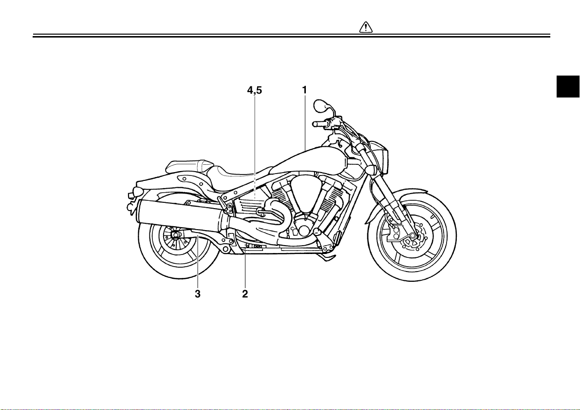
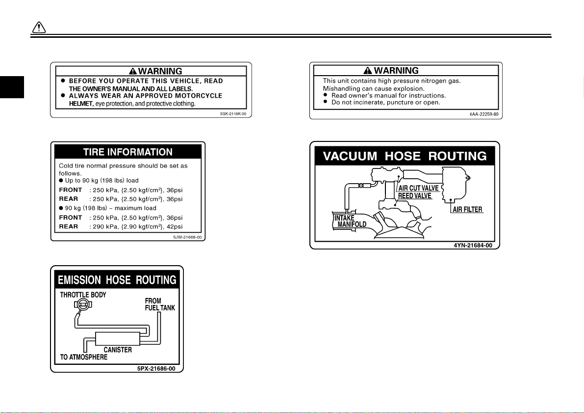
Location of important labels
Please read the following important labels carefully before operating this vehicle.
SAFETY INFORMATION
1-6
1
2
4
California only
1
3
5
California only
DESCRIPTION
2-1
2
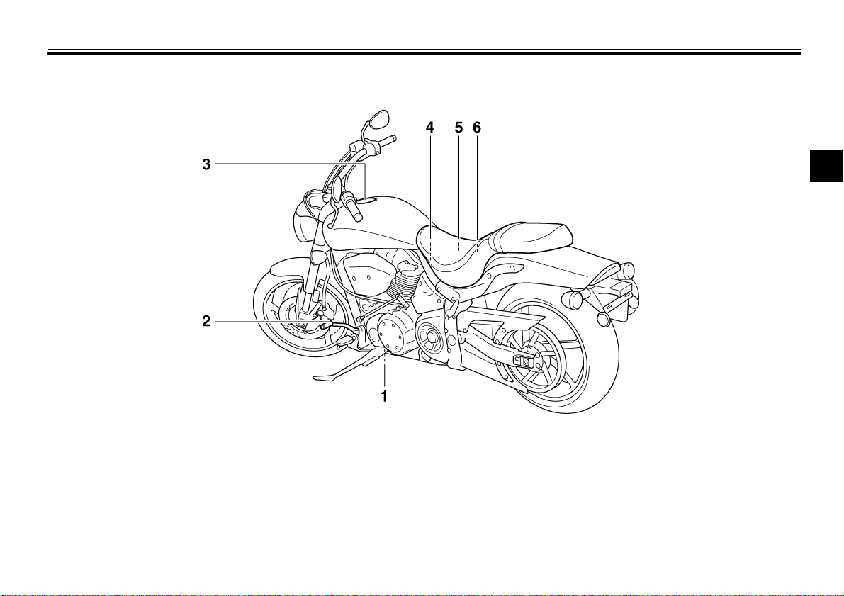
EAU10410
Left view
1. Engine oil drain bolt (crankcase) (page 6-9)
2. Shift pedal (page 3-6)
3. Fuel tank cap (page 3-7)
4. Helmet holder (page 3-10)
5. Fuses (page 6-32)
6. Owner’s tool kit (page 6-1)
DESCRIPTION
2-2
2
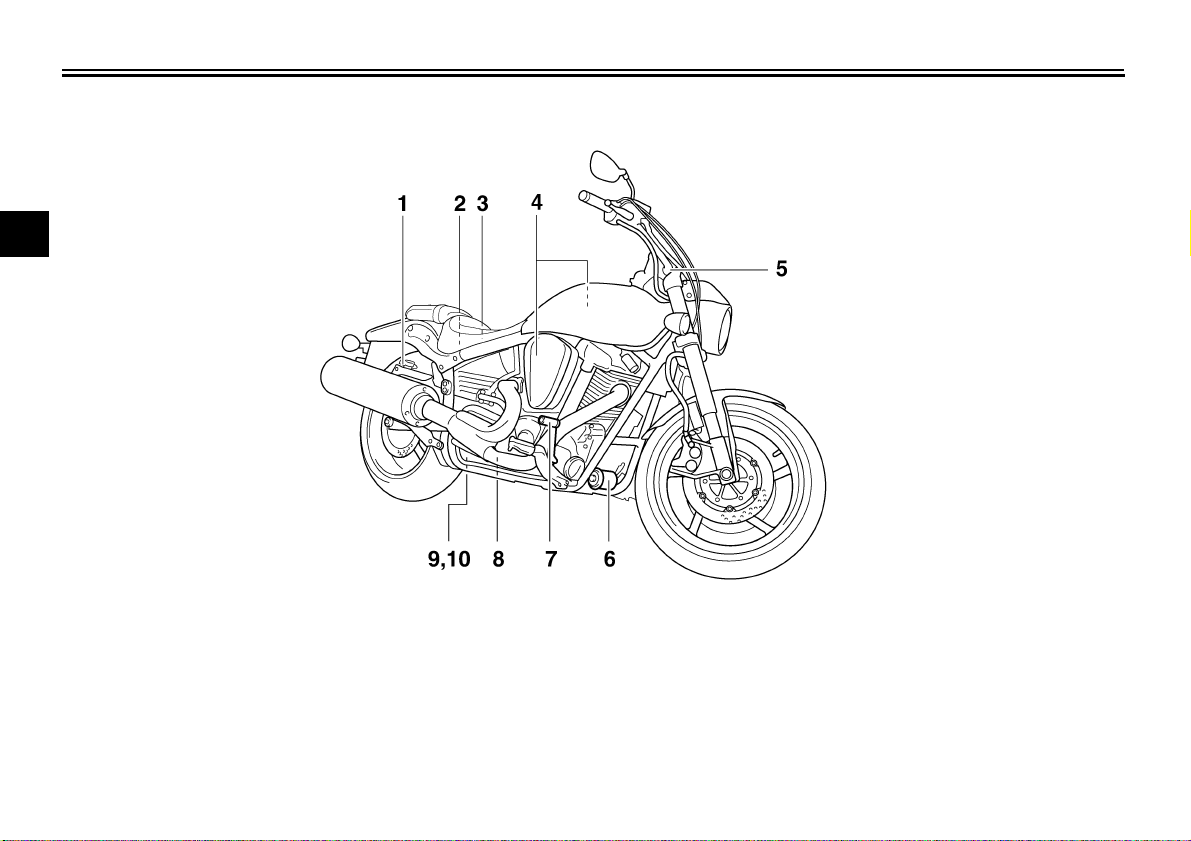
EAU10420
Right view
1. Rear brake fluid reservoir (page 6-23)
2. Battery (page 6-31)
3. Engine oil filler cap (page 6-9)
4. Air filter element (page 6-13)
5. Front fork spring preload adjusting bolt (page 3-10)
6. Engine oil filter cartridge (page 6-9)
7. Brake pedal (page 3-7)
8. Engine oil drain bolt (oil tank) (page 6-9)
9. Shock absorber assembly spring preload adjusting nut (page 3-11)
10.Shock absorber assembly rebound damping force adjusting knob
(page 3-11)
DESCRIPTION
2-3
2
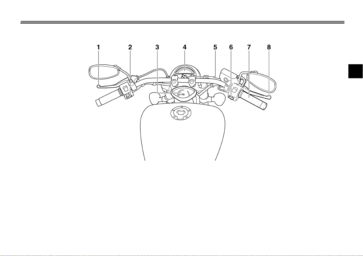
EAU10430
Controls and instruments
1. Clutch lever (page 3-6)
2. Left handlebar switches (page 3-5)
3. Speedometer (page 3-3)
4. Tachometer unit (page 3-3)
5. Main switch/steering lock (page 3-1)
6. Right handlebar switches (page 3-5)
7. Throttle grip (page 6-16)
8. Brake lever (page 3-7)
INSTRUMENT AND CONTROL FUNCTIONS
3-1
3
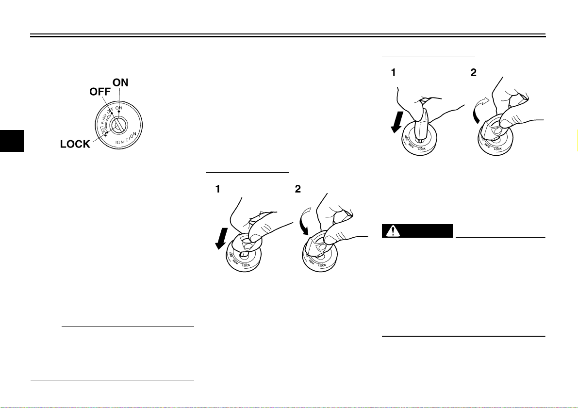
EAU10460
Main switch/steering lock
The main switch/steering lock controls
the ignition and lighting systems, and is
used to lock the steering. The various
positions are described below.
EAU10540
ON
All electrical circuits are supplied with
power, and the meter lighting, taillight,
license plate light and position lights
come on, and the engine can be start-
ed. The key cannot be removed.
NOTE:
The headlight comes on automatically
when the engine is started and stays on
until the key is turned to “OFF”, even if
the engine stalls.
EAU10660
OFF
All electrical systems are off. The key
can be removed.
EAU10680
LOCK
The steering is locked, and all electrical
systems are off. The key can be re-
moved.
To lock the steering
1. Turn the handlebars all the way to
the left.
2. Push the key in from the “OFF” po-
sition, and then turn it to “LOCK”
while still pushing it.
3. Remove the key.
To unlock the steering
Push the key in, and then turn it to
“OFF” while still pushing it.
WARNING
EWA10060
Never turn the key to “OFF” or
“LOCK” while the vehicle is moving,
otherwise the electrical systems will
be switched off, which may result in
loss of control or an accident. Make
sure that the vehicle is stopped be-
fore turning the key to “OFF” or
“LOCK”.
1. Push.
2. Turn.
1. Push.
2. Turn.
INSTRUMENT AND CONTROL FUNCTIONS
3-2
3
EAU11003
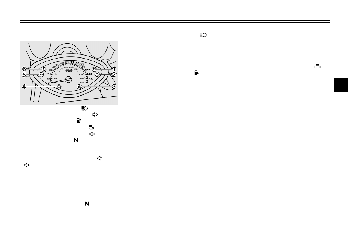
Indicator and warning lights
EAU11030
Turn signal indicator lights “” and
“”
The corresponding indicator light flash-
es when the turn signal switch is
pushed to the left or right.
EAU11060
Neutral indicator light “”
This indicator light comes on when the
transmission is in the neutral position.
EAU11080
High beam indicator light “”
This indicator light comes on when the
high beam of the headlight is switched
on.
EAU11361
Fuel level warning light “”
This warning light comes on when the
fuel level drops below approximately
3.0 L (0.79 US gal) (0.66 Imp.gal).
When this occurs, refuel as soon as
possible.
The electrical circuit of the warning light
can be checked by turning the key to
“ON”.
If the warning light does not come on
for a few seconds, and then go off,
have a Yamaha dealer check the elec-
trical circuit.
NOTE:
This model is also equipped with a self-
diagnosis device for the fuel level de-
tection circuit. If the fuel level detection
circuit is defective, the following cycle
will be repeated until the malfunction is
corrected: The fuel level warning light
will flash eight times, and then go off for
3.0 seconds. If this occurs, have a
Yamaha dealer check the vehicle.
EAU11480
Engine trouble warning light “”
This warning light comes on when an
electrical circuit monitoring the engine
is defective. When this occurs, have a
Yamaha dealer check the self-diagno-
sis system.
The electrical circuit of the warning light
can be checked by turning the key to
“ON”. If the warning light does not come
on for a few seconds, then go off, have
a Yamaha dealer check the electrical
circuit.
1. High beam indicator light “”
2. Right turn signal indicator light “”
3. Fuel level warning light “”
4. Engine trouble warning light “”
5. Left turn signal indicator light “”
6. Neutral indicator light “”
INSTRUMENT AND CONTROL FUNCTIONS
3-3
3
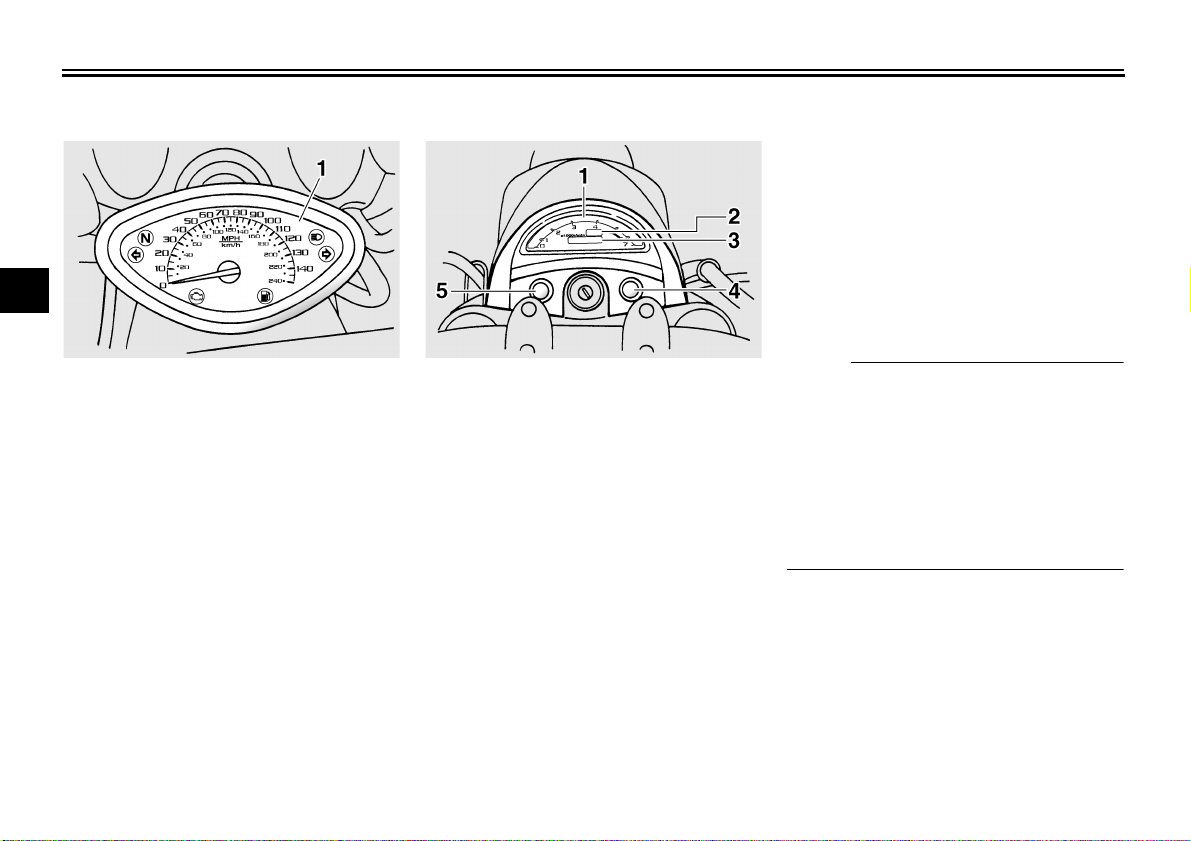
EAU11601
Speedometer
The speedometer shows the riding
speed.
When the key is turned to “ON”, the
speedometer needle will sweep once
across the speed range and then return
to zero in order to test the electrical cir-
cuit.
EAU34031
Tachometer unit
The LCD tachometer allows the rider to
monitor the engine speed and keep it
within the ideal power range.
When the key is turned to “ON”, all of
the display segments of the LCD ta-
chometer will appear one after the oth-
er across the r/min range and then
disappear, in order to test the electrical
circuit.
The tachometer unit is equipped with
the following:
● an odometer (which shows the to-
tal distance traveled)
● two tripmeters (which show the
distance traveled since they were
last set to zero)
● a fuel reserve tripmeter (which
shows the distance traveled since
the fuel level warning light came
on)
● a meter lighting control
● a clock
● a self diagnosis device
NOTE:
● Be sure to turn the key to “ON” be-
fore using the “SELECT” and “RE-
SET” buttons.
● To switch the odometer, the trip-
meters and the fuel reserve trip-
meter displays between kilometers
and miles, press the “SELECT”
button for at least two seconds.
1. Speedometer 1. Tachometer
2. Clock
3. Odometer/tripmeter/fuel reserve tripmeter
4. “RESET” button
5. “SELECT” button
INSTRUMENT AND CONTROL FUNCTIONS
3-4
3
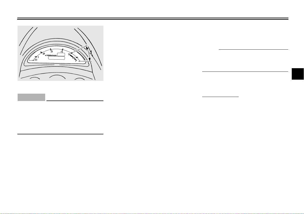
CAUTION:
ECA11551
Do not operate the engine in the ta-
chometer red zone. If operated in the
red zone, the tachometer segments
will start flashing to notify the rider.
Red zone: 5000 r/min and above
Odometer and tripmeter modes
Pushing the “SELECT” button switches
the display between the odometer
mode “ODO” and the tripmeter modes
“TRIP 1” and “TRIP 2” in the following
order:
ODO → TRIP 1 → TRIP 2 → ODO
If the fuel level warning light comes on
(see page 3-2), the odometer display
will automatically change to the fuel re-
serve tripmeter mode “TRIP F” and
start counting the distance traveled
from that point. In that case, pushing
the “SELECT” button switches the dis-
play between the various tripmeter and
odometer modes in the following order:
TRIP F → TRIP 1 → TRIP 2 → ODO →
TRIP F
To reset a tripmeter, select it by push-
ing the “SELECT” button, and then
push the “RESET” button for at least
one second. If you do not reset the fuel
reserve tripmeter manually, it will reset
itself automatically and the display will
return to the prior mode after refueling
and 90 seconds have passed.
Meter lighting control mode
1. Turn the key to “OFF”.
2. Push and hold the “SELECT” but-
ton.
3. Turn the key to “ON”, and then af-
ter five seconds, release the “SE-
LECT” button.
4. Push the “RESET” button to select
the desired brightness.
5. Push the “SELECT” button to set
the brightness level.
6. Turn the key to “OFF”.
NOTE:
When adjusting the meter lighting, the
odometer display will indicate the
brightness level.
Clock mode
To set the clock:
1. Push the “SELECT” button and
“RESET” button together for at
least two seconds.
2. When the hour digits start flashing,
push the “RESET” button to set the
hours.
3. Push the “SELECT” button, and
the minute digits will start flashing.
4. Push the “RESET” button to set
the minutes.
5. Push the “SELECT” button and
then release it to start the clock.
Self diagnosis device
This model is equipped with a self-diag-
nosis device for various electrical cir-
cuits.
1. Tachometer red zone
INSTRUMENT AND CONTROL FUNCTIONS
3-5
3
If any of those circuits are defective, the
engine trouble warning light will come
on and the clock display will indicate a
two-digit error code (e.g., 11, 12, 13).
If the clock display indicates such an er-
ror code, note the code number, and
then have a Yamaha dealer check the
vehicle.
CAUTION:
ECA11540
If the clock display indicates an error
code, the vehicle should be checked
as soon as possible in order to avoid
engine damage.
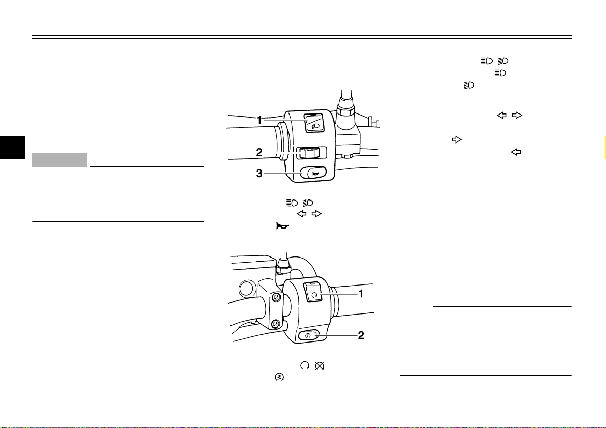
EAU12343
Handlebar switches
Left
Right
EAU12400
Dimmer switch “ / ”
Set this switch to “” for the high
beam and to “” for the low beam.
EAU12430
Turn signal switch “ / ”
To signal a right-hand turn, push this
switch to “”. To signal a left-hand
turn, push this switch to “”. When re-
leased, the switch returns to the center
position.
Since this model is equipped with a
self-canceling system, the turn signal
lights will self-cancel after the vehicle
has traveled both about 150 m (490 ft)
and for approximately 15 seconds.
However, the turn signal lights can also
be canceled manually by pushing the
switch in after it has returned to the cen-
ter position.
NOTE:
The self-canceling system only oper-
ates when the vehicle is moving, so that
the turn signal lights will not self-cancel
while you are stopped at an intersec-
tion.
1. Dimmer switch “ / ”
2. Turn signal switch “ / ”
3. Horn switch “”
1. Engine stop switch “ / ”
2. Start switch “”
INSTRUMENT AND CONTROL FUNCTIONS
3-6
3
EAU12500
Horn switch “”
Press this switch to sound the horn.
EAU12660
Engine stop switch “ / ”
Set this switch to “” before starting
the engine. Set this switch to “” to
stop the engine in case of an emergen-
cy, such as when the vehicle overturns
or when the throttle cable is stuck.
EAU12710
Start switch “”
Push this switch to crank the engine
with the starter.
CAUTION:
ECA10050
See page 5-1 for starting instruc-
tions prior to starting the engine.
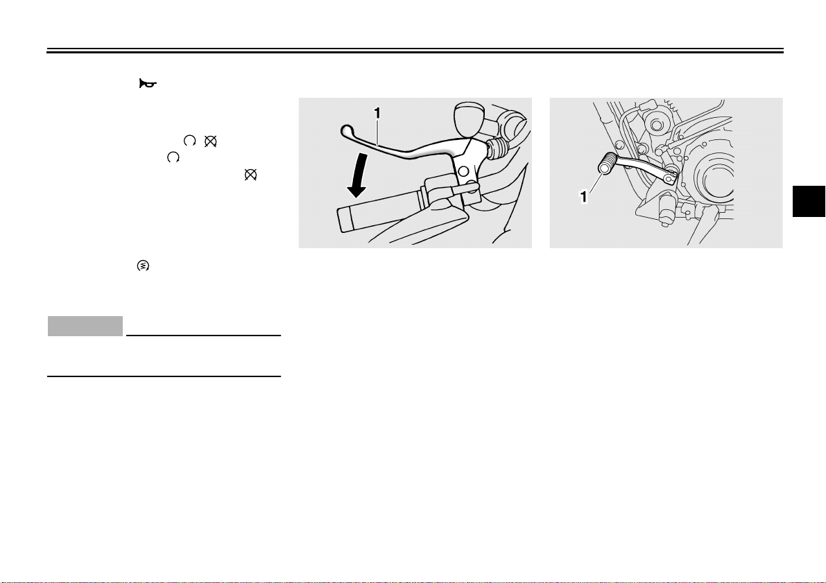
EAU12820
Clutch lever
The clutch lever is located at the left
handlebar grip. To disengage the
clutch, pull the lever toward the handle-
bar grip. To engage the clutch, release
the lever. The lever should be pulled
rapidly and released slowly for smooth
clutch operation.
The clutch lever is equipped with a
clutch switch, which is part of the igni-
tion circuit cut-off system. (See page
3-14.)
EAU12870
Shift pedal
The shift pedal is located on the left
side of the engine and is used in com-
bination with the clutch lever when
shifting the gears of the 5-speed con-
stant-mesh transmission equipped on
this motorcycle.
1. Clutch lever 1. Shift pedal
INSTRUMENT AND CONTROL FUNCTIONS
3-7
3
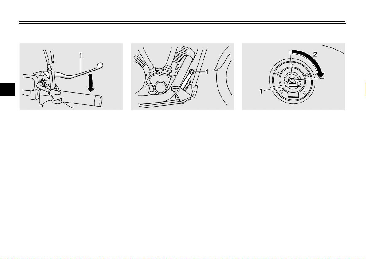
EAU12890
Brake lever
The brake lever is located at the right
handlebar grip. To apply the front
brake, pull the lever toward the handle-
bar grip.
EAU12941
Brake pedal
The brake pedal is on the right side of
the motorcycle. To apply the rear
brake, press down on the brake pedal.
EAU13070
Fuel tank cap
To open the fuel tank cap
Open the fuel tank cap lock cover, in-
sert the key into the lock, and then turn
it 1/4 turn clockwise. The lock will be re-
leased and the fuel tank cap can be
opened.
To close the fuel tank cap
1. Push the fuel tank cap into position
with the key inserted in the lock.
2. Turn the key counterclockwise to
the original position, remove it, and
then close the lock cover.
1. Brake lever 1. Brake pedal 1. Fuel tank cap lock cover
2. Unlock.
INSTRUMENT AND CONTROL FUNCTIONS
3-8
3
NOTE:
The fuel tank cap cannot be closed un-
less the key is in the lock. In addition,
the key cannot be removed if the cap is
not properly closed and locked.
WARNING
EWA11090
Make sure that the fuel tank cap is
properly closed before riding.
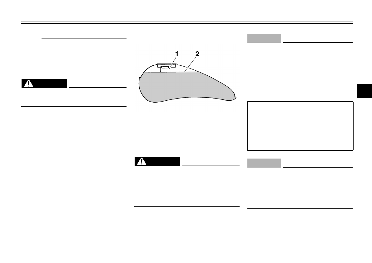
EAU13210
Fuel
Make sure that there is sufficient fuel in
the tank. Fill the fuel tank to the bottom
of the filler tube as shown.
WARNING
EWA10880
● Do not overfill the fuel tank, oth-
erwise it may overflow when the
fuel warms up and expands.
● Avoid spilling fuel on the hot en-
gine.
CAUTION:
ECA10070
Immediately wipe off spilled fuel
with a clean, dry, soft cloth, since
fuel may deteriorate painted surfac-
es or plastic parts.
EAU13360
CAUTION:
ECA11400
Use only unleaded gasoline. The use
of leaded gasoline will cause severe
damage to internal engine parts,
such as the valves and piston rings,
as well as to the exhaust system.
Your Yamaha engine has been de-
signed to use regular unleaded gaso-
line with a pump octane number
[(R+M)/2] of 86 or higher, or a research
octane number of 91 or higher. If
1. Fuel tank filler tube
2. Fuel level
Recommended fuel
UNLEADED GASOLINE ONLY
Fuel tank capacity:
15.0 L (3.96 US gal) (3.30 Imp.gal)
Fuel reserve amount (when the fuel
level warning light comes on):
3.0 L (0.79 US gal) (0.66 Imp.gal)
INSTRUMENT AND CONTROL FUNCTIONS
3-9
3
knocking (or pinging) occurs, use a
gasoline of a different brand or premi-
um unleaded fuel. Use of unleaded fuel
will extend spark plug life and reduce
maintenance costs.
Gasohol
There are two types of gasohol: gaso-
hol containing ethanol and that contain-
ing methanol. Gasohol containing
ethanol can be used if the ethanol con-
tent does not exceed 10%. Gasohol
containing methanol is not recom-
mended by Yamaha because it can
cause damage to the fuel system or ve-
hicle performance problems.
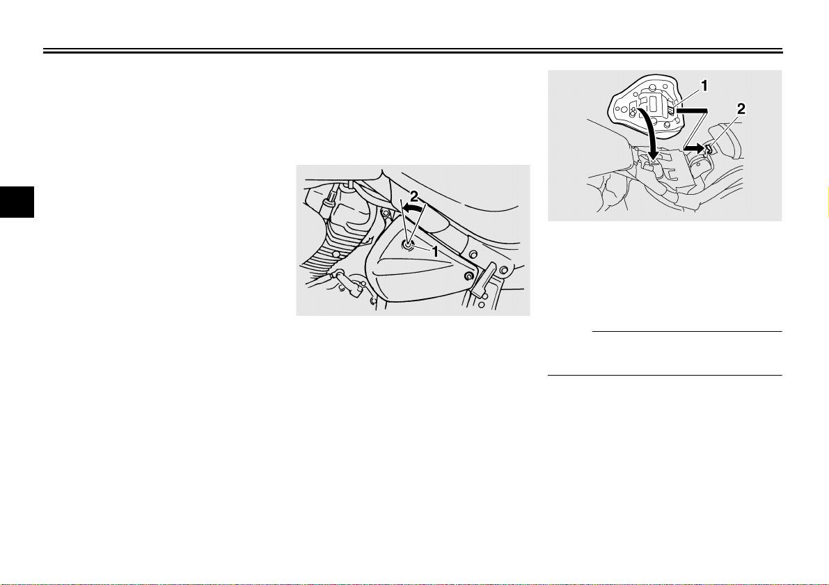
EAU34042
Rider seat
To remove the rider seat
1. Insert the key into the seat lock,
and then turn it counterclockwise.
2. While holding the key in that posi-
tion, lift the front of the seat up, and
then pull the seat off.
To install the rider seat
1. Insert the projection on the rear of
the seat into the seat holder as
shown.
2. Push the front of the seat down to
lock it in place.
3. Remove the key.
NOTE:
Make sure that the seat is properly se-
cured before riding.
1. Seat lock
2. Unlock.
1. Projection
2. Seat holder
INSTRUMENT AND CONTROL FUNCTIONS
3-10
3
EAU14320
Helmet holder
The helmet holder is located under the
rider seat.
To secure a helmet to the helmet
holder
1. Remove the rider seat. (See page
3-9.)
2. Attach the helmet to the helmet
holder, and then securely install
the seat.
WARNING
EWA10160
Never ride with a helmet attached to
the helmet holder, since the helmet
may hit objects, causing loss of con-
trol and possibly an accident.
To release the helmet from the hel-
met holder
Remove the rider seat, remove the hel-
met from the helmet holder, and then
install the seat.
EAU14720
Adjusting the front fork
This front fork is equipped with spring
preload adjusting bolts.
WARNING
EWA10180
Always adjust both fork legs equal-
ly, otherwise poor handling and loss
of stability may result.
Adjust the spring preload as follows.
To increase the spring preload and
thereby harden the suspension, turn
the adjusting bolt on each fork leg in di-
rection (a). To decrease the spring pre-
load and thereby soften the
suspension, turn the adjusting bolt on
each fork leg in direction (b).
1. Helmet holder
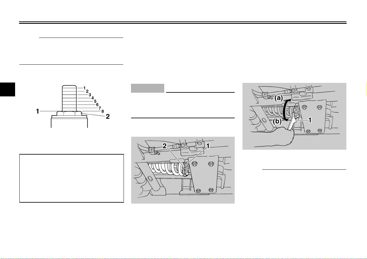
1. Spring preload adjusting bolt
INSTRUMENT AND CONTROL FUNCTIONS
3-11
3
NOTE:
Align the appropriate groove on the ad-
justing mechanism with the top of the
front fork cap bolt.
EAU34061
Adjusting the shock absorber
assembly
This shock absorber assembly is
equipped with a spring preload adjust-
ing nut and a rebound damping force
adjusting knob.
CAUTION:
ECA10100
Never attempt to turn an adjusting
mechanism beyond the maximum or
minimum settings.
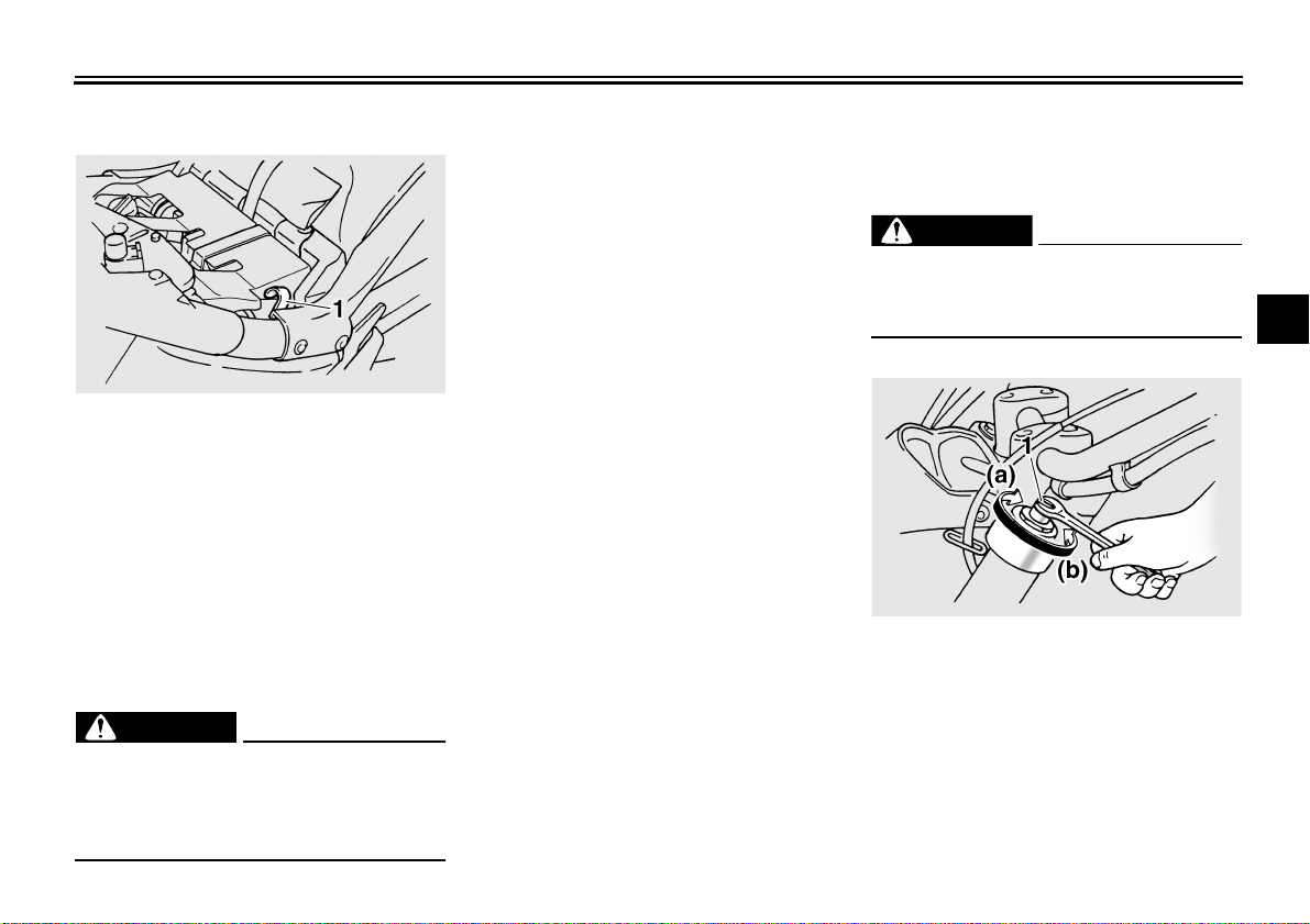
Spring preload
1. Loosen the locknut.
2. To increase the spring preload and
thereby harden the suspension,
turn the adjusting nut in direction
(a). To decrease the spring pre-
load and thereby soften the sus-
pension, turn the adjusting nut in
direction (b).
NOTE:
● Use the special wrench included in
the owner’s tool kit to make the ad-
justment.
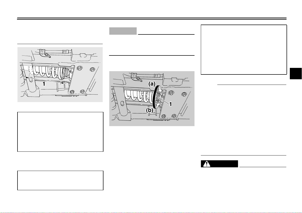
● The spring preload setting is deter-
mined by measuring distance A,
shown in the illustration. The long-
er distance A is, the lower the
spring preload; the shorter dis-
tance A is, the higher the spring
1. Current setting
2. Front fork cap bolt
Spring preload setting:
Minimum (soft):
8
Standard:
5
Maximum (hard):
1
1. Locknut
2. Spring preload adjusting nut
1. Special wrench
INSTRUMENT AND CONTROL FUNCTIONS
3-12
3
preload. With each complete turn
of the adjusting nut, distance A is
changed by 1.5 mm (0.06 in).
3. Tighten the locknut to the specified
torque.
CAUTION:
ECA11240
Always tighten the locknut against
the adjusting nut, and then tighten
the locknut to the specified torque.
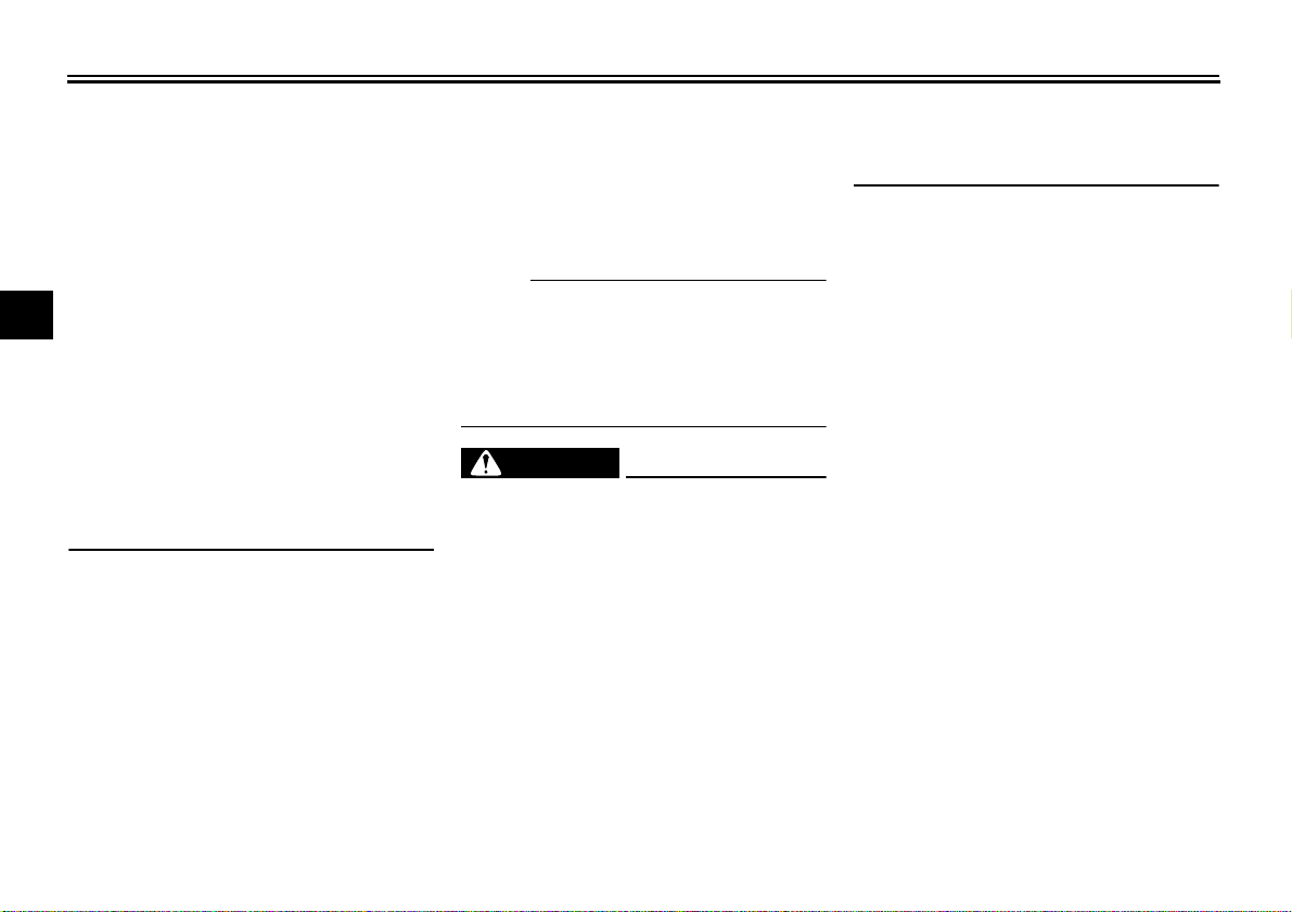
Rebound damping force
To increase the rebound damping force
and thereby harden the rebound damp-
ing, turn the adjusting knob in direction
(a). To decrease the rebound damping
force and thereby soften the rebound
damping, turn the adjusting knob in di-
rection (b).
N
O
TE:
Although the total number of clicks of
the damping force adjusting mecha-
nism may not exactly match the above
specifications due to small differences
in production, the actual number of
clicks always represents the entire ad-
justing range. To obtain a precise ad-
justment, it would be advisable to check
the number of clicks of the damping
force adjusting mechanism and to mod-
ify the specifications as necessary.
WARNING
EWA10220
This shock absorber contains highly
pressurized nitrogen gas. For prop-
er handling, read and understand
the following information before
handling the shock absorber. The
1. Distance A
Spring preload:
Minimum (hard):
Distance A = 163 mm (6.42 in)
Standard:
Distance A = 172 mm (6.77 in)
Maximum (soft):
Distance A = 174 mm (6.85 in)
Tightening torque:
Locknut:
50 Nm (5.0 m·kgf, 36 ft·lbf)
1. Rebound damping force adjusting knob
Rebound damping setting:
Minimum (soft)
20 click(s) in direction (b)*
Standard
10 click(s) in direction (b)*
Maximum (hard)
3 click(s) in direction (b)*
* With the adjusting knob fully turned
in direction (a)
INSTRUMENT AND CONTROL FUNCTIONS
3-13
3
manufacturer cannot be held re-
sponsible for property damage or
personal injury that may result from
improper handling.
● Do not tamper with or attempt to
open the gas cylinder.
● Do not subject the shock ab-
sorber to an open flame or other
high heat sources, otherwise it
may explode due to excessive
gas pressure.
● Do not deform or damage the
gas cylinder in any way, as this
will result in poor damping per-
formance.
● Always have a Yamaha dealer
service the shock absorber.
EAU15301
Sidestand
The sidestand is located on the left side
of the frame. Raise the sidestand or
lower it with your foot while holding the
vehicle upright.
NOTE:
The built-in sidestand switch is part of
the ignition circuit cut-off system, which
cuts the ignition in certain situations.
(See further down for an explanation of
the ignition circuit cut-off system.)
WARNING
EWA10240
The vehicle must not be ridden with
the sidestand down, or if the side-
stand cannot be properly moved up
(or does not stay up), otherwise the
sidestand could contact the ground
and distract the operator, resulting
in a possible loss of control.
Yamaha’s ignition circuit cut-off
system has been designed to assist
the operator in fulfilling the respon-
sibility of raising the sidestand be-
fore starting off. Therefore, check
this system regularly as described
below and have a Yamaha dealer re-
pair it if it does not function proper-
ly.
Loading...