


XVZ13TF(L) 1999
Table of contents
 Loading...


EAS00001
XVZ13TF (L)
SERVICE MANUAL
1999 by Yamaha Motor Co., Ltd.
First edition, January 1999
All rights reserved. Any reproduction or
unauthorized use without the written
permission of Yamaha Motor Co., Ltd
is expressly prohibited.
NOTE:
CAUTION:
EAS00003
NOTICE
This manual was produced by the Y amaha Motor Company , Ltd. primarily for use by Y amaha dealers
and their qualified mechanics. It is not possible to include all the knowledge of a mechanic in one manu-
al. Therefore, anyone who uses this book to perform maintenance and repairs on Yamaha vehicles
should have a basic understanding of mechanics and the techniques to repair these types of vehicles.
Repair and maintenance work attempted by anyone without this knowledge is likely to render the ve-
hicle unsafe and unfit for use.
This model has been designed and manufactured to perform within certain specifications in regard to
performance and emissions. Proper service with the correct tools in necessary to ensure that the ve-
hicle will operate as designed. If there is any question about a service procedure, it is imperative that
you contact a Y amaha dealer for any service information changes that apply to this model. This policy
is intended to provide the customer with the most satisfaction from his vehicle and to conform with fed-
eral environmental quality objectives.
Y amaha Motor Company, Ltd. is continually striving to improve all its models. Modifications and signifi-
cant changes in specifications or procedures will be forwarded to all authorized Y amaha dealers and
will appear in future editions of this manual where applicable.
This Service Manual contains information regarding periodic maintenance to the emission control
system. Please read this material carefully.
Designs and specifications are subject to change without notice.
EAS00004
IMPORTANT INFORMATION
Particularly important information is distinguished in this manual by the following notations.
The Safety Alert Symbol means ATTENTION! BECOME ALERT! YOUR
SAFETY IS INVOLVED!
Failure to follow WARNING instructions could result in severe injury or death
to
the motorcycle operator, a bystander or a person inspecting or repairing the
motorcycle.
A CAUTION indicates special precautions that must be taken to avoid damage
to the motorcycle.
NOTE: A NOTE provides key information to make procedures easier or clearer.
12
4
5
7
3
8
6
EAS00007
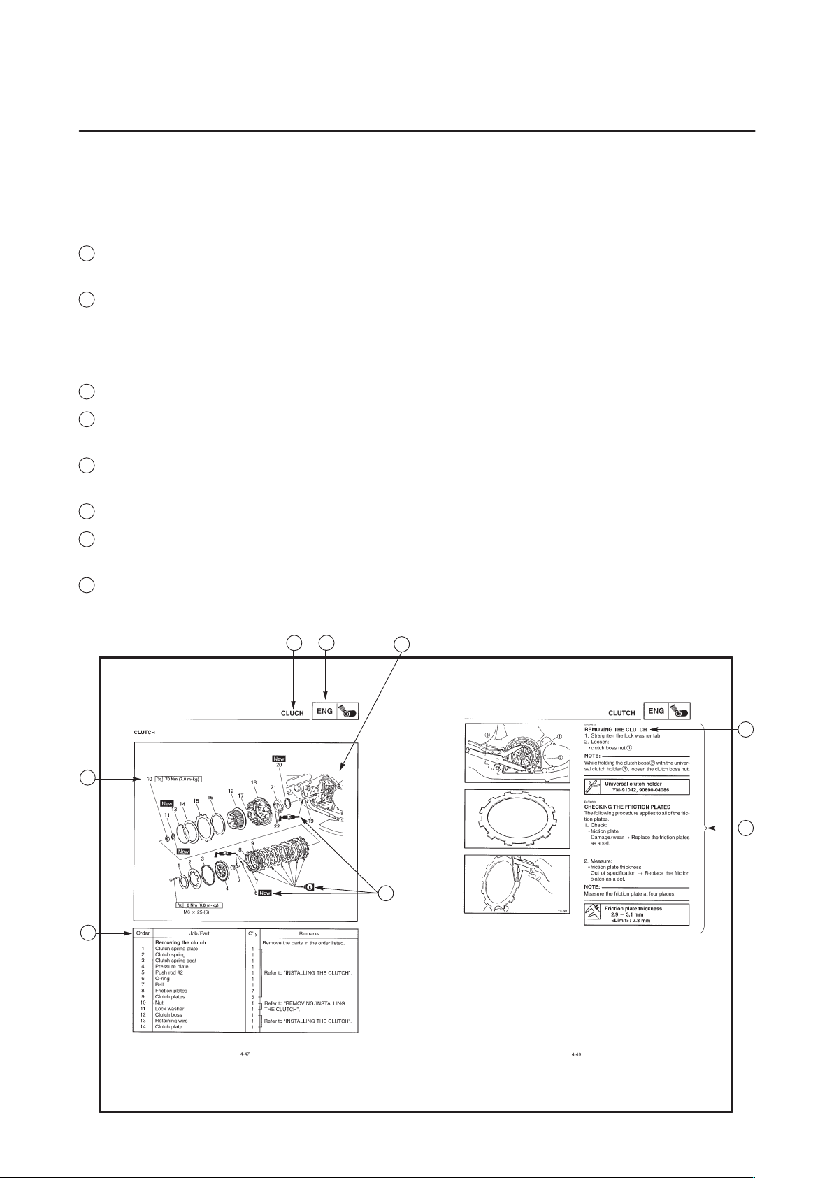
HOW TO USE THIS MANUAL
This manual is intended as a handy , easy-to-read reference book for the mechanic. Comprehensive
explanations of all installation, removal, disassembly , assembly , repair and inspection procedures are
laid out with the individual steps in sequential order.
1
The manual is divided into chapters. An abbreviation and symbol in the upper right corner of each
page indicate the current chapter. Refer to “SYMBOLS” on the following page.
2
Each chapter is divided into sections. The current section title is shown at the top of each page,
except in Chapter 3 (“Periodic Inspections and Adjustments”), where the sub-section title(-s) appear.
(In Chapter 3, “Periodic Inspection and Adjustments”, the sub-section title appears at the top of each
page, instead of the section title.)
3
Sub-section titles appear in smaller print than the section title.
4
To help identify parts and clarify procedure steps, there are exploded diagrams at the start of each
removal and disassembly section.
5
Numbers are given in the order of the jobs in the exploded diagram. A circled number indicates a
disassembly step.
6
Symbols indicate parts to be lubricated or replaced (see “SYMBOLS”).
7
A job instruction chart accompanies the exploded diagram, providing the order of jobs, names of
parts, notes in jobs, etc.
8
Jobs requiring more information (such as special tools and technical data) are described sequen-
tially .
22
1
3
5
7
9
2
4
8
6
24 25
2321
19 2018
16 1715
1413
11 12
10
GEN
INFO
SPEC
ENG
CARB
ELECCHAS
COOL
CHK
ADJ
TRBL
SHTG
EAS00008
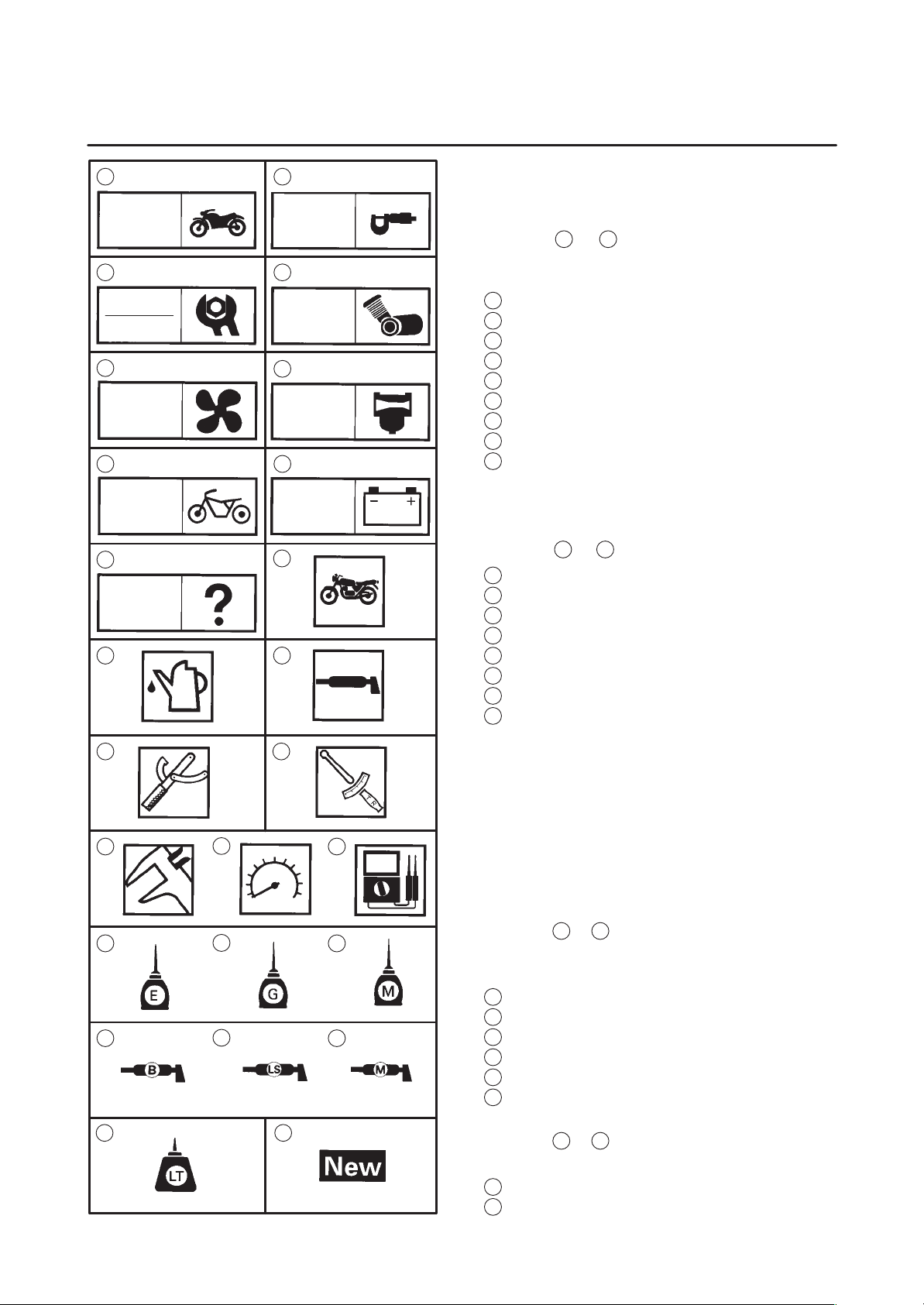
SYMBOLS
The following symbols are not relevant to every
vehicle.
Symbols
1
to
9
indicate the subject of each
chapter.
1
General information
2
Specifications
3
Periodic inspections and adjustments
4
Engine
5
Cooling system
6
Carburetor(-s)
7
Chassis
8
Electrical system
9
Troubleshooting
Symbols
10
to
17
indicate the following.
10
Serviceable with engine mounted
11
Filling fluid
12
Lubricant
13
Special tool
14
Tightening torque
15
Wear limit, clearance
16
Engine speed
17
Electrical data
Symbols
18
to
23
in the exploded diagrams indi-
cate the types of lubricants and lubrication
points.
18
Engine oil
19
Gear oil
20
Molybdenum disulfide oil
21
Wheel bearing grease
22
Lithium soap base grease
23
Molybdenum disulfide grease
Symbols
24
to
25
in the exploded diagrams indi-
cate the following:
24
Apply locking agent (LOCTITE
R
)
25
Replace the part

GENERAL INFORMATION
SPECIFICATIONS
PERIODIC INSPECTIONS AND
ADJUSTMENTS
ENGINE
COOLING SYSTEM
CARBURETORS
CHASSIS
ELECTRICAL SYSTEM
TROUBLESHOOTING
GEN
INFO
1
SPEC
2
3
ENG
4
COOL
5
CARB
6
CHAS
7
ELEC
8
TRBL
SHTG
9
CHK
ADJ
EAS00012
TABLE OF CONTENTS

GEN
INFO
1

GEN
INFO
CONTENTS
GENERAL INFORMATION
MOTORCYCLE IDENTIFICATION 1-1. . . . . . . . . . . . . . . . . . . . . . . . . . . . . . .
VEHICLE IDENTIFICATION NUMBER 1-1. . . . . . . . . . . . . . . . . . . . . . . . .
MODEL CODE 1-1. . . . . . . . . . . . . . . . . . . . . . . . . . . . . . . . . . . . . . . . . . . . .
FEA TURES 1-2. . . . . . . . . . . . . . . . . . . . . . . . . . . . . . . . . . . . . . . . . . . . . . . . . . .
CRUISE CONTROL 1-2. . . . . . . . . . . . . . . . . . . . . . . . . . . . . . . . . . . . . . . . .
DIGITAL SPEEDOMETER 1-4. . . . . . . . . . . . . . . . . . . . . . . . . . . . . . . . . . .
AUDIO SYSTEM 1-5. . . . . . . . . . . . . . . . . . . . . . . . . . . . . . . . . . . . . . . . . . . .
IMPORTANT INFORMATION 1-13. . . . . . . . . . . . . . . . . . . . . . . . . . . . . . . . . . . .
PREPARATION FOR REMOVAL AND DISASSEMBLY 1-13. . . . . . . . . .
REPLACEMENT PARTS 1-13. . . . . . . . . . . . . . . . . . . . . . . . . . . . . . . . . . . . .
GASKETS, OIL SEALS AND O-RINGS 1-13. . . . . . . . . . . . . . . . . . . . . . . .
LOCK WASHERS/PLATES AND COTTER PINS 1-14. . . . . . . . . . . . . . . .
BEARINGS AND OIL SEALS 1-14. . . . . . . . . . . . . . . . . . . . . . . . . . . . . . . . .
CIRCLIPS 1-14. . . . . . . . . . . . . . . . . . . . . . . . . . . . . . . . . . . . . . . . . . . . . . . . . .
CHECKING THE CONNECTIONS 1-15. . . . . . . . . . . . . . . . . . . . . . . . . . . . . . .
SPECIAL TOOLS 1-16. . . . . . . . . . . . . . . . . . . . . . . . . . . . . . . . . . . . . . . . . . . . . .

GEN
INFO
1-1
MOTORCYCLE IDENTIFICATION
GEN
INFO
EAS00014
GENERAL INFORMATION
MOTORCYCLE IDENTIFICATION
EAS00017
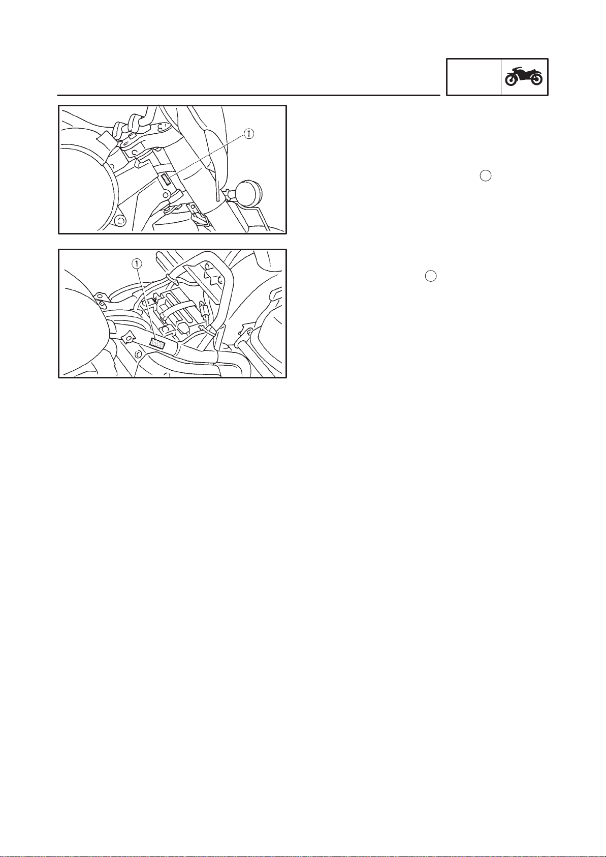
VEHICLE IDENTIFICATION NUMBER
The vehicle identification number
1
is stamped
into the right side of the steering head.
EAS00018
MODEL CODE
The model code label
1
is affixed to the frame.
This information will be needed to order spare
parts.
1-2
FEATURES
GEN
INFO
CAUTION:
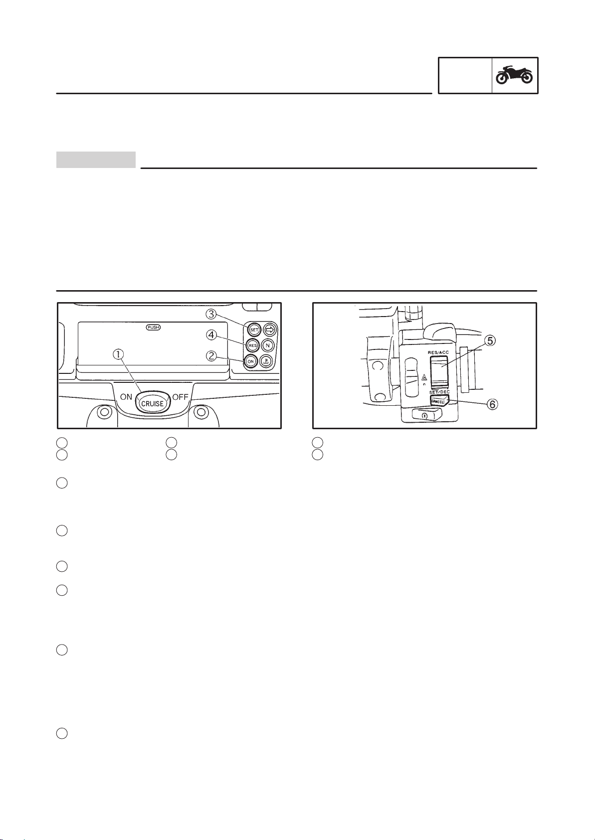
3 “SET” indicator light
4 “RES” indicator light
5 Cruise control switch
6 “CANCEL” switch
EAS00019
FEATURES
CRUISE CONTROL
This motorcycle is equipped with cruise control which designed to maintain a set speed.
Giving a severe load like using as a trailer/tractor or driving on a steep slope could remove the
cruise control.
Do not set the cruise control while idling the rear tires for the preparation.
Do not disassemble the vacuum pump.
Never remove the cruise control actuator rubber cover. When putting it back, bolts or other
parts will be caught and the cruise control wire can be locked.
Do not remove the air cleaner cover of the vacuum pump in order not to cause a malfunction in
cancellation of the cruise control by dirt, trash etc.
Do not drive without holding the steering wheel whether the cruise control is ON or OFF.
1
“CRUISE” switch
2
“ON” indicator light
Cruise control switch functions
1
“CRUISE” switch
Push this switch to “ON” when the cruise control system is preset. The “ON” indicator light will come on.
Once the switch is released it will return to the center (Hold) position.
To cancel the cruise control system, push the switch to “OFF” or main switch to the “OFF” position.
2
“ON” indicator light
This indicator light comes on when the cruise control systems preset (when “ON” is selected by the
“CRUISE” switch).
3
“SET” indicator light
This indicator light comes on when the motorcycle is operating at a set speed.
4
“RES” indicator light
This light comes on when the set speed, which is cancelled by any steps, is memorized and when the
operating speed is in the range of approx. 50-130 km/h.
If the resume system is operated while this light is on, it continues flashing until the speed returns to that
memorized.
5
Cruise control switch
This switch is capable of the following controls.
Refer to the “Operation chart” for details.
Set speed ride
Minute adjustment of set speed
Consecutive adjustment of set speed
“RESUME” system
6
“CANCEL” switch
Push this switch to cancel the set speed ride in the cruise control system.
1-3
FEATURES
GEN
INFO
SET
CRUISE
SET
RES
ON
(After1.4sec)
SET
RES
ON
SET
RES
ON
Flash
Out of range
Out of range
Mannual
acceleration
cancel
Rear brake
Clutch
SET Front brake
Resume
Cruise SW
ON
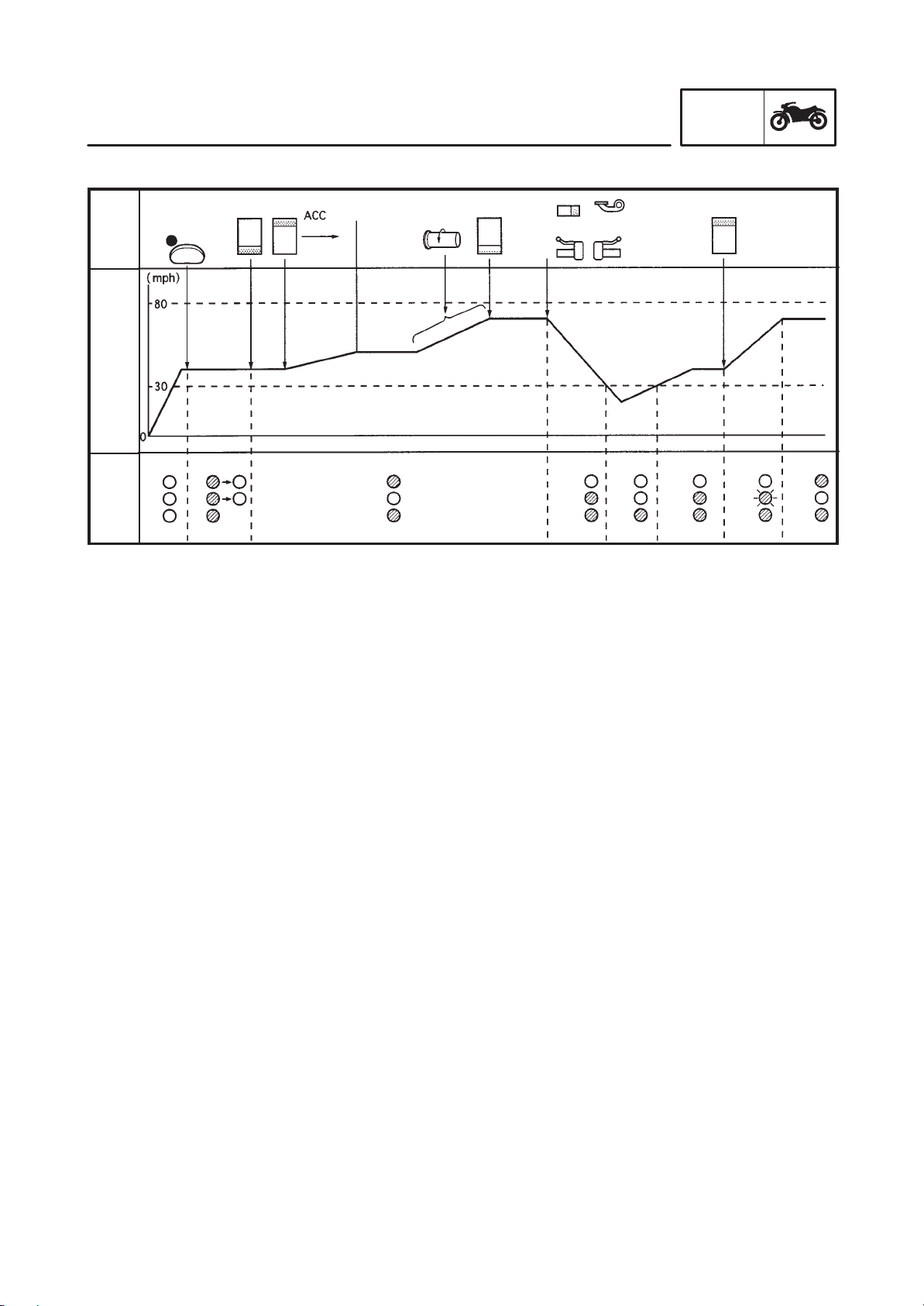
Operation chart
Opera-
tion
Speed
Indica-
tor
Cruise control function
1) The cruise control can only be activated when riding in 4th, 5th gear and traveling between the
speed of 50 and 130 km/h.
2) To operate the system, the “CRUISE” switch should be turned “ON”.
3) When push the cruise control switch to “SET”, the cruise control system will be set the set speed.
4) By pushing (in shorter than 0.5 seconds), the control switch in the direction of either “ACC” or “DEC”,
the set speed can be changed in increments or decrements of approximately 1.6 km/h.
5) If the control switch is held in the “ACC” or “DEC” position (longer than 0.5 seconds), the speed can
be successively increased or decreased slowly.
6) The cruise control will be deactivated if the front or rear brake is applied or if the clutch is disengaged
or if the “CANCEL” switch is pushed.
7) After canceling, the speed is returned to the one set before the cancellation by pushing the control
switch once in the “RES” direction.
8) Auto cruise function is canceled;
a. In case of current speed drops 8 km/h less than the originally set speed.
b. In case of gear position is moved to gears other than of 4th, 5th.
c. In case of systems fines any faulty signal in the following systems.
Control unit
Actuator cable
Logical error in cut off signal
Error signal in speed sensor signal
Error signal in engine revolution
Cruise control switch lead (“SET”/“RES”)
9) When main switch is cut off once, “resume” is canceled.
1-4
FEATURES
GEN
INFO
NOTE:
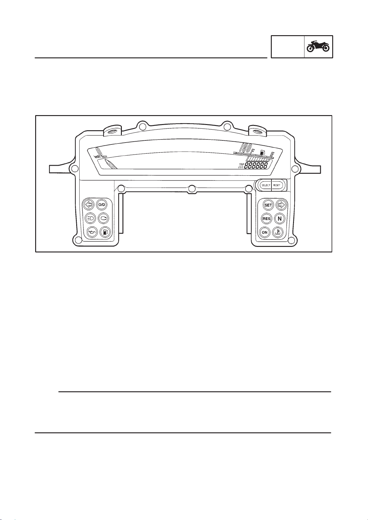
DIGITAL SPEEDOMETER
This speedometer is equipped with:
An odometer
Two trip odometers
A fuel reserve trip meter
A clock
Odometer and trip meter modes
1) Selecting a mode
Push the “SELECT” button to change between the odometer mode “ODO” and the trip odometer
modes “TRIP 1” and “TRIP 2” in the following order.
“ODO” “TRIP 1” “TRIP 2” “ODO”
If the fuel level indicator light comes on, the odometer display will automatically change to the fuel re-
serve trip meter mode “TRIP F” and start counting the distance traveled from that point.
Push the “SELECT” button to change between the fuel reserve tripmeter, trip odometer and odometer
modes in the following order:
“TRIP F” “TRIP 1” “TRIP 2” “ODO” “TRIP F”
2) Resetting a meter
T o reset a trip odometer to 0.0, select it by pushing the “SELECT” button and push the “RESET” button.
To reset the fuel reserve trip meter, select it by pushing the “SELECT” button and push the “RESET”
button. The display will return to prior mode (“ODO”, “TRIP 1” or “TRIP 2”).
If you do not reset the fuel reserve trip meter manually , it will automatically reset and retum to “TRIP 1”
after refueling and the motorcycle has traveled both 5km.
If the fuel reserve trip meter appears, and a different mode was NOT selected prior to resetting the fuel
reserve trip meter, the display always returns to the “TRIP 1” mode.
If the fuel reserve trip meter appears, and a different mode was selected prior to resetting the fuel
reserve trip meter, the display automatically returns to the prior mode.
1-5
FEATURES
GEN
INFO
NOTE:
Clock mode
To change the display to the clock mode, push both the “SELECT” and “RESET” buttons.
To change the display back to odometer mode, push the “RESET” button.
1) To set the clock
a. Push both the “SELECT” and “RESET” buttons for at least two seconds.
b. When the hour digits start flashing, push the “RESET” button to set the hours.
c. Push the “SELECT” button and the minute digits will start flashing.
d. Push the “RESET” button to set the minutes.
e. Push the “SELECT” button to start the clock.
After setting the clock, be sure to push the “SELECT” button before turning the main switch to “OFF”,
otherwise the clock will not be set.
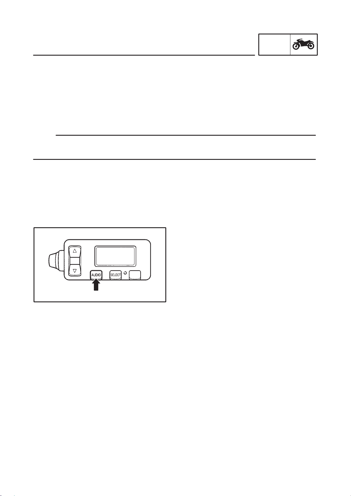
AUDIO SYSTEM
1. POWERING ON/OFF THE AUDIO SYS-
TEM
Turning on/off the audio system
Turn the main switch to the “ACC” or “ON” posi-
tion.
To turn on the power for the audio system,
push the audio button “AUDIO”.
To turn off the audio system, push the audio
button “AUDIO” continuously for 1 second or
more.
1-6
FEATURES
GEN
INFO
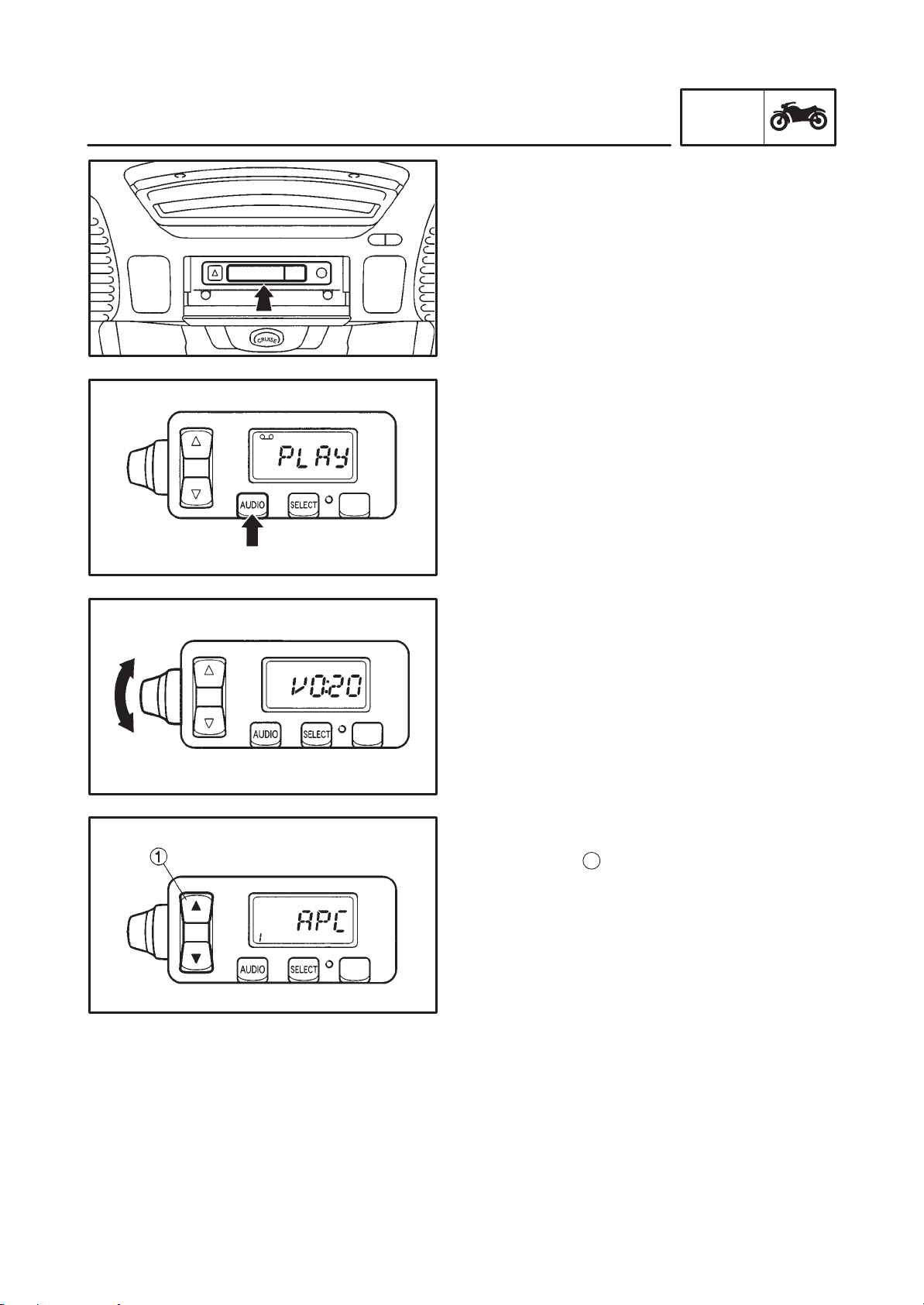
2. CASSETTE DESK OPERATION
The cassette tape deck has the following func-
tions.
Song search
Change tape play direction
Dolby noise reduction
Blank tape skip
a. Turn the main switch to the “ACC” or “ON”
position and push the “AUDIO”button to turn
on the power.
b. Insert a cassette tape into the cassette deck.
c. If a tape is aleady loaded in the cassette
deck, push the “AUDIO” button until “PLAY”
appears.
The tape will start playing.
d. Turn the volume control knob to set the vol-
ume level. The volume level can be set from
0 to 30.
Track searching
To search for a song on the tape, push the up-
down switch
1
for less than one second. The
“APC” (auto program control) indicator will ap-
pear in the display.
Push the witch once for each song to be skipped.
Pushing the switch in direction “n” will search in
the forward direction.
Pushing the switch in direction “o” will search in
the reserve direction.
When searching in the forward direction, the num-
ber of song that are being skipped will appear.
(i.e., “1”, meaning one track is being skipped)
When searching the reverse direction, the num-
ber of song that are being skipped will appear
along with a minus sign before the number. (i.e.,
“-1”, meaning one song is being skipped)
The maxmum number of songs that can be
skipped in either direction is 9.
To stop a searching operation, push the up-
down button in the opposite direction that it was
originally pushed.
1-7
FEATURES
GEN
INFO
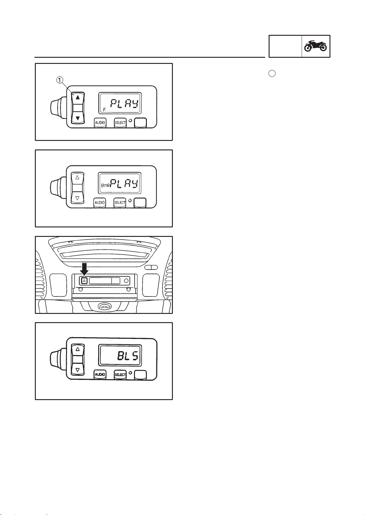
Reserving tape play direction
Push the up-down button
1
in either direction
for more than one second to reverse tape play .
When the tape is playing the forward direction,
the “F” indicator will appear.
When the tape is playing in the reverse direc-
tion, the “R” indicator will appear.
Dolby noise reduction
The Dolby noise reduction can be turned on or
off by pushing the “EJECT” button for at least
two seconds.
When the noise reduction is on, the “BNR” indi-
cator appears in the display.
Ejecting the cassette tape
Push the “EJECT” button to eject the tape from
the cassette dack.
Blank skipping
When there is a blank portion on the cassette
tape the “BLS” indicator light will come on and
the cassette deck automatically fast forwards
the tape to the next track.
1-8
FEATURES
GEN
INFO
TAPE FM1 FM2 FM3
AUX. CD(option) AM
3. RADIO OPERATION
The radio has the following functions.
Switching the receiving band
Switching the receiving station
Automatic tuning (Seek)
Manual tuning
Programing preset stations in memory
Automatic writing of stations in memory (Auto
store operation)
Switching the receiving bands
This radio system has 3 bands for FM and 1
band for AM. Select a band by pushing the “AU-
DIO” button for less than 1 second.
The display will change as follows.
Automatic tuning (Seek operation)
Push the up-down switch
1
in either direction
and hold it for as least 1 second.
The tuner will automatically stop at the first sta-
tion that has a strong enough radio wave.
Manually turning
When a radio wave is too weak to be picked up
automatically, it can be selected manually as
follows.
Push the “SELECT” button until “RADIO” sta-
tion appears.
Push the up-down switch
1
for less than 1 se-
cond in either direction and the ferequency will
change in 0.1 MHz steps for FM and in 9 kHz for
AM.
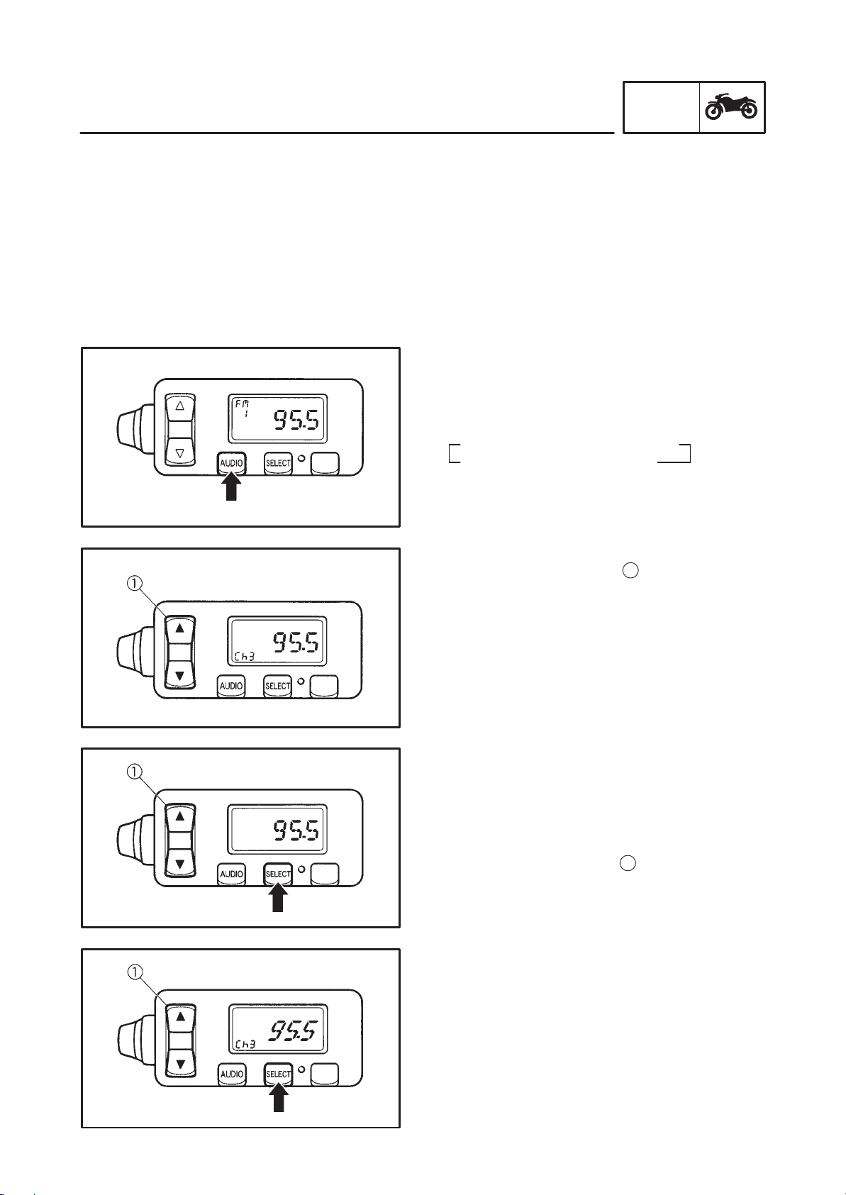
Presetting station in memory
Station can be preset either automatically or
manually. 6 stations can be set for each band.
Preset station either manually or automatically
by the following procedure.
a. Select the station desired to be preset.
b. Push the “SELECT” button for as least 2 se-
conds unitl the radio frequency and the chan-
nel “Ch” start flashing.
1-9
FEATURES
GEN
INFO
NOTE:
c. Push the up-down switch
1
in either direc-
tion to select the channel number to be set for
the current station. (Ch1, Ch2, Ch3, Ch4,
Ch5 and Ch6)
d. Press the “SELECT” button to programing
the channel in memory.
Repeat this procedure for the remaining sta-
tions desired to be preset in the memory.
Stations can be also be automatically preset by
the following procedure.
a. Push the “SELECT” button until the radio fre-
quency and the channel “Ch” start flashing.
b. Push the up-down button in either direction
for at least 1 second to automatically tune in
a station.
c. When the desired station is found, push the
up-down switch for less than one second to
select the channel number to be set for that
station.
d. Push the “SELECT” button to programing the
channels in memory.
e. Repeat this procedure for the remaining sta-
tions desived to be preset in memory.
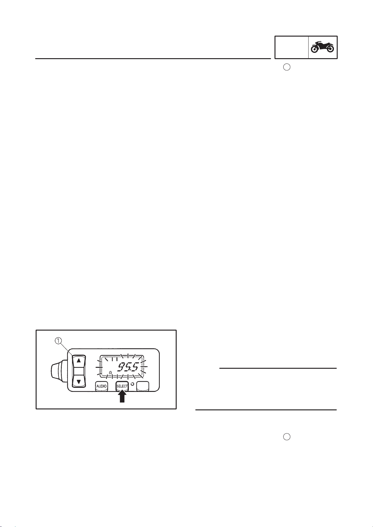
Programing preset stations in memory auto-
matically
Setting up to 6 channels can be made by the fol-
lowing procedure.
Stations will be starting from the station preset
at chanel 6.
It is recommended to use this function only in
areas with strong radio frequencies.
a. Push the “SELECT” button until the radio fre-
quency and the channel “Ch” start flashing.
b. Push the up-down switch
1
in either direc-
tion to select channel “A”.
c. Press the “SELECT” button to start the ran-
dom channel selection and the tuner will au-
tomatically write the channels in memory.
1-10
FEATURES
GEN
INFO
TAPE FM1 FM2 FM3
AUX. CD(option) AM
OUTPUT BASS TREB FADE
RADIO station AVC INT.VOL
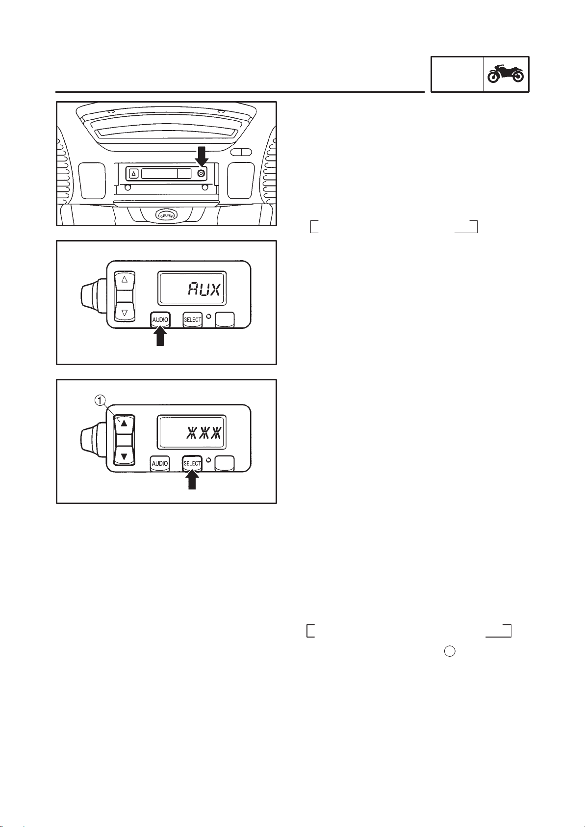
“AUX” (Auxiliary) operation
Auxiliary audio equipment can be used to play
through the audio system.
a. Insert the output plug of the auxiliary equip-
ment into the jack located at the right side of
the dassette deck.
b. Push the “AUDIO” button until “AUX” ap-
pears and the auxiliary equipment can be
used to play through the audio system.
5. BASIC SETTINGS
AUDIO system
The following settings can be made in the audio
system.
Selecting output between speakers and a head-
set assembly
Controlling bass level
Controlling treble level
Controlling fader (balance between the front
and the rear speakers)
Controlling intercom volume level
Changing auto volume level
Setting procedure
The following setting procedures apply to the
audio system, auxiliary mode and CD Changer.
a. Select the desired setting mode by pushing
the “SELECT” button. On each press of the
button, the mode changes as follows.
Audio system
b. Push the up-down switch
1
in either direc-
tion to change the setting for any mode.
1-11
FEATURES
GEN
INFO
NOTE:
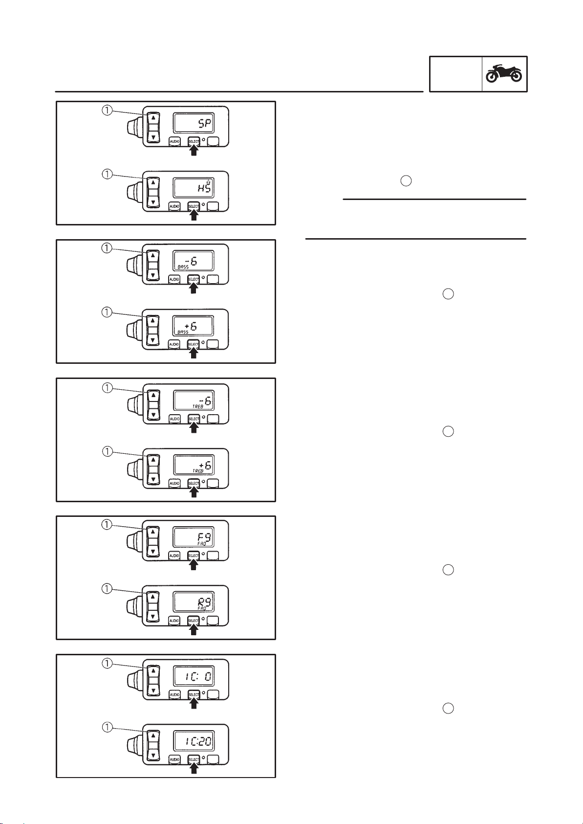
Selecting the output for speaker or headset
(optional)
To select the output for speaker or headset,
push the “SELECT” button and the “SP” (speak-
er) or “HS” (headset) indicator will appear. To
change between speaker and headset, push
the up-down switch
1
in either direction.
The speaker and headset cannot be used the
same time.
Controlling the bass level
a. To control the bass level, push the “SELECT”
button until the “BASS” indicator appears.
b. Push the up-down switch
1
in either direc-
tion to change the level.
Controllingthe treble level
a. To control the treble level, push the “SE-
LECT” button until the “TREB” indicator ap-
pears.
b. Push the up-down switch
1
in either direc-
tion to change the level.
The treble level can be set from –6 to +6.
Controlling the fader (balance between front
and rear speakers)
a. To control the fader , push the “SELECT” but-
ton until the “FAD” indicator appears.
b. Push the up-down switch
1
in either direc-
tion to change the balance.
The fader level can be adjusted from F9 to
R9.
Controlling the intercom volume level
a. To control the intercom volume level, push
the “SELECT” button until the “IC:” indicator
appears.
b. Push the up-down switch
1
in either direc-
tion to change the volume level.
The intercom volume level can be set from 0
to 20.
1-12
FEATURES
GEN
INFO
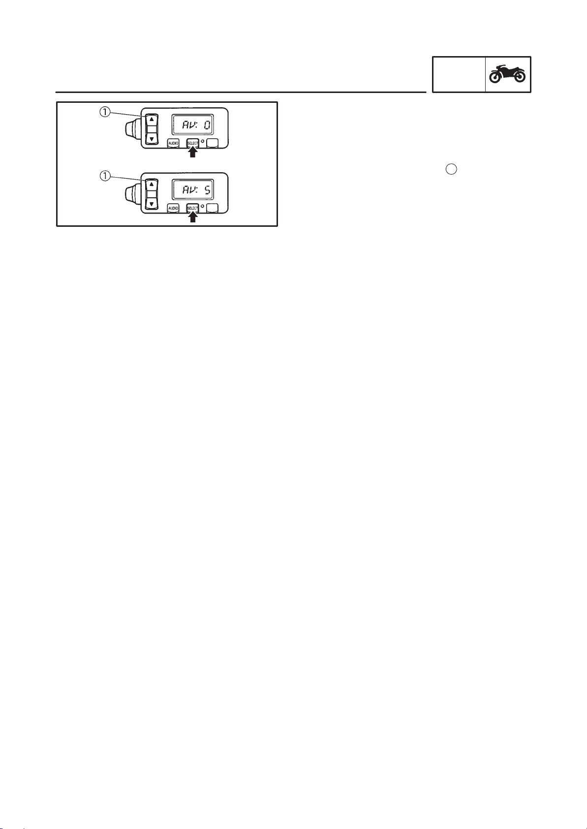
Changing the level for auto volume control
system
a. To control the level for the auto volume con-
trol system, push the “SELECT” button untill
the “AV:” indicator appears.
b. Push the up-down switch
1
in either direc-
tion to change the volume level.
The auto volume control rate of compensa-
tion can be adjusted from 0 to 5.
1-13
IMPORTANT INFORMATION
GEN
INFO
EAS00020
IMPORTANT INFORMATION
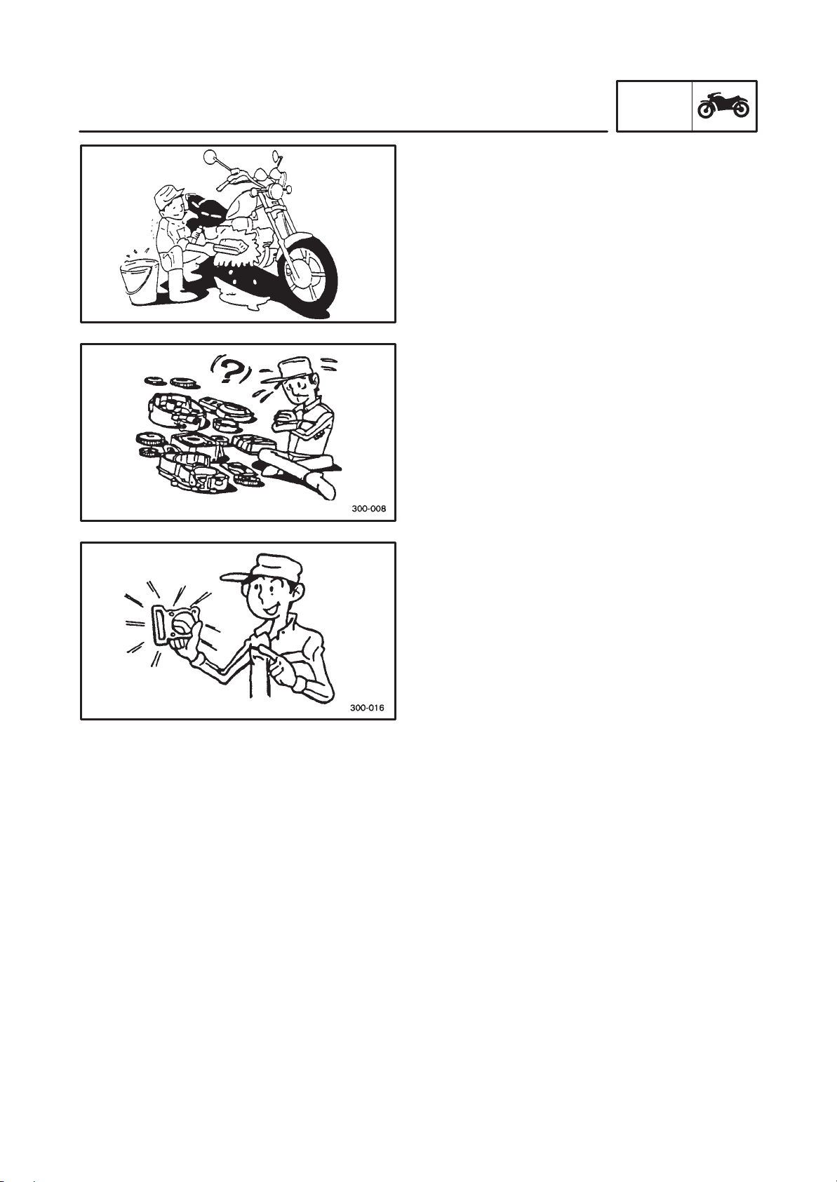
PREPARATION FOR REMOVAL AND DIS-
ASSEMBLY
1. Before removal and disassembly, remove all
dirt, mud, dust and foreign material.
2. Use only the proper tools and cleaning
equipment.
Refer to the “SPECIAL TOOLS” section.
3. When disassembling, always keep mated
parts together. This includes gears, cylin-
ders, pistons and other parts that have been
“mated” through normal wear.
Mated parts must always be reused or re-
placed as an assembly.
4. During disassembly, clean all of the parts
and place them in trays in the order of disas-
sembly . This will speed up assembly and al-
low for the correct installation of all parts.
5. Keep all parts away from any source of fire.
EAS00021
REPLACEMENT PARTS
1. Use only genuine Yamaha parts for all re-
placements. Use oil and grease recom-
mended by Yamaha for all lubrication jobs.
Other brands may be similar in-function and
appearance, but inferior in quality.
EAS00022
GASKETS, OIL SEALS AND O-RINGS
1. When overhauling the engine, replace all
gaskets, seals and O-rings. All gasket sur-
faces, oil seal lips and O-rings must be
cleaned.
2. During reassembly, properly oil all mating
parts and bearings and apply grease onto
the oil seal lips.
1-14
IMPORTANT INFORMATION
GEN
INFO
CAUTION:
EAS00023
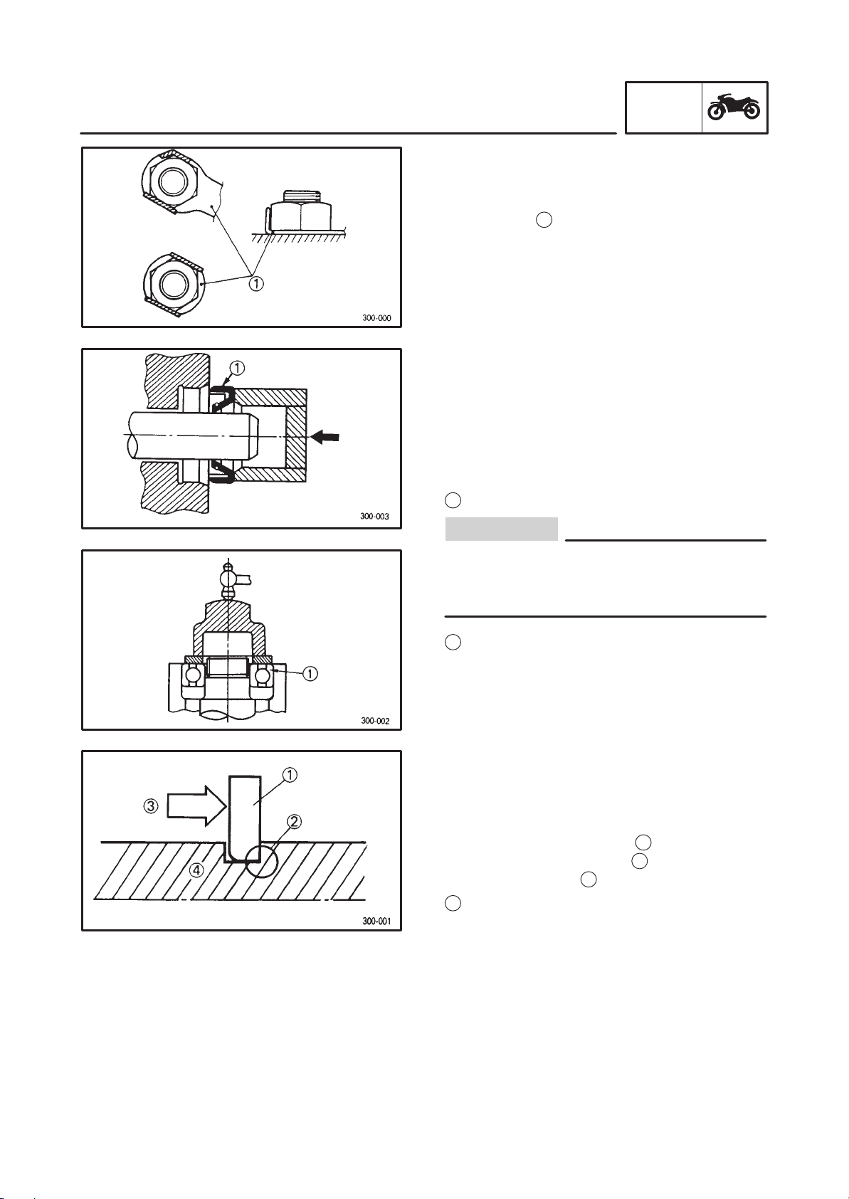
LOCK WASHERS/PLATES AND COTTER
PINS
1. After removal, replace all lock wash-
ers/plates
1
and cotter pins. After the bolt or
nut has been tightened to specification, bend
the lock tabs along a flat of the bolt or nut.
EAS00024
BEARINGS AND OIL SEALS
1. Install bearings and oil seals so that the
manufacturer’s marks or numbers are vis-
ible. When installing oil seals, apply a light
coat of lithium soap base grease onto the oil
seal lips. Oil bearings liberally when instal-
ling, if appropriate.
1
Oil seal
Do not spin the bearing with compressed air
because this will damage the bearing sur-
faces.
1
Bearing
EAS00025
CIRCLIPS
1. Before reassembly , check all circlips careful-
ly and replace damaged or distorted circlips.
Always replace piston pin clips after one use.
When installing a circlip
1
, make sure that
the sharp-edged corner
2
is positioned op-
posite the thrust
3
that the circlip receives.
4
Shaft
1-15
CHECKING THE CONNECTIONS
GEN
INFO
NOTE:
NOTE:
NOTE:
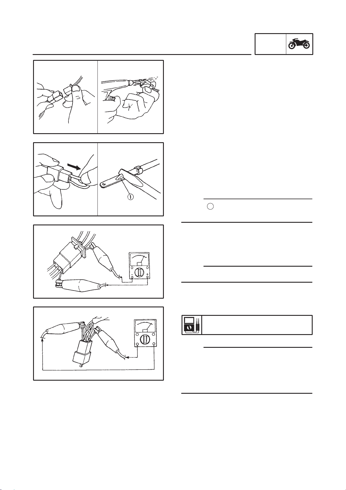
EAS00026
CHECKING THE CONNECTIONS
Check the leads, couplers, and connectors for
stains, rust, moisture, etc.
1. Disconnect:
lead
coupler
connector
2. Check:
lead
coupler
connector
Moisture Dry with an air blower.
Rust/stains Connect and disconnect sev-
eral times.
3. Check:
all connections
Loose connection Connect properly.
If the pin
1
on the terminal is flattened, bend it
up.
4. Connect:
lead
coupler
connector
Make sure that all connections are tight.
5. Check:
continuity
(with a pocket tester)
Pocket tester
YU-03112,90890-03112
If there is no continuity, clean the terminals.
When checking the wire harness, perform
steps 1 to 3.
As a quick remedy, use a contact revitalizer
available at most part stores.
1-16
SPECIAL TOOLS
GEN
INFO
EAS00027
SPECIAL TOOLS
The following special tools are necessary for complete and accurate tune-up and assembly . Use only
the appropriate special tools as this will help prevent damage caused by the use of inappropriate tools
or improvised techniques. Special tools, part umbers or both may differ depending on the country.
When placing an order, refer to the list provided below to avoid any mistakes.
P/N.YM-, YU-
FOr US, CDN
YS-, YK- ACC-
P/N.90890-
Except for US, CDN
Tool No.
Tool name/Usage Illustration
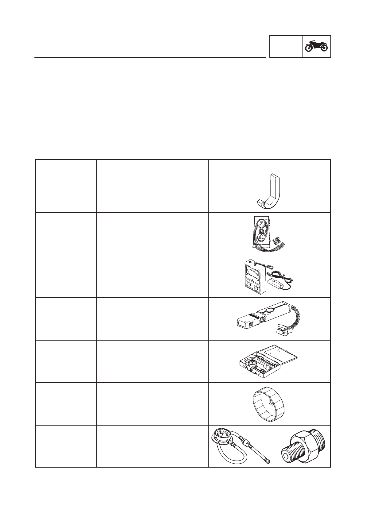
YM-33961
90890-04105
Tappet adjusting tool
This tool is needed to rotate the
camshaft for access to the valve lift-
er and valve pad
YU-08030-A
90890-03094
Vacuum gauge
This gauge is needed for carburetor
synchronization.
YU-08036-A
90890-031 13
Engine tachometer
This tool is needed for observing en-
gine rpm.
YU-33277-A
90890-03141
Timing light
This tool is necessary for checking
ignition timing.
YU-33223
90890-03081
Compression gauge/Set
These tools are needed to measure
engine compression.
YU-38411
90890-01426
Oil filter wrench
This tool is needed to remove and
install the oil filter.
Gauge
90890-03153
Adapter
90890-03124
Pressure gauge/adapter
These tools are needed to measure
engine oil pressure.
1-17
SPECIAL TOOLS
GEN
INFO
Tool No. Tool name/Usage Illustration
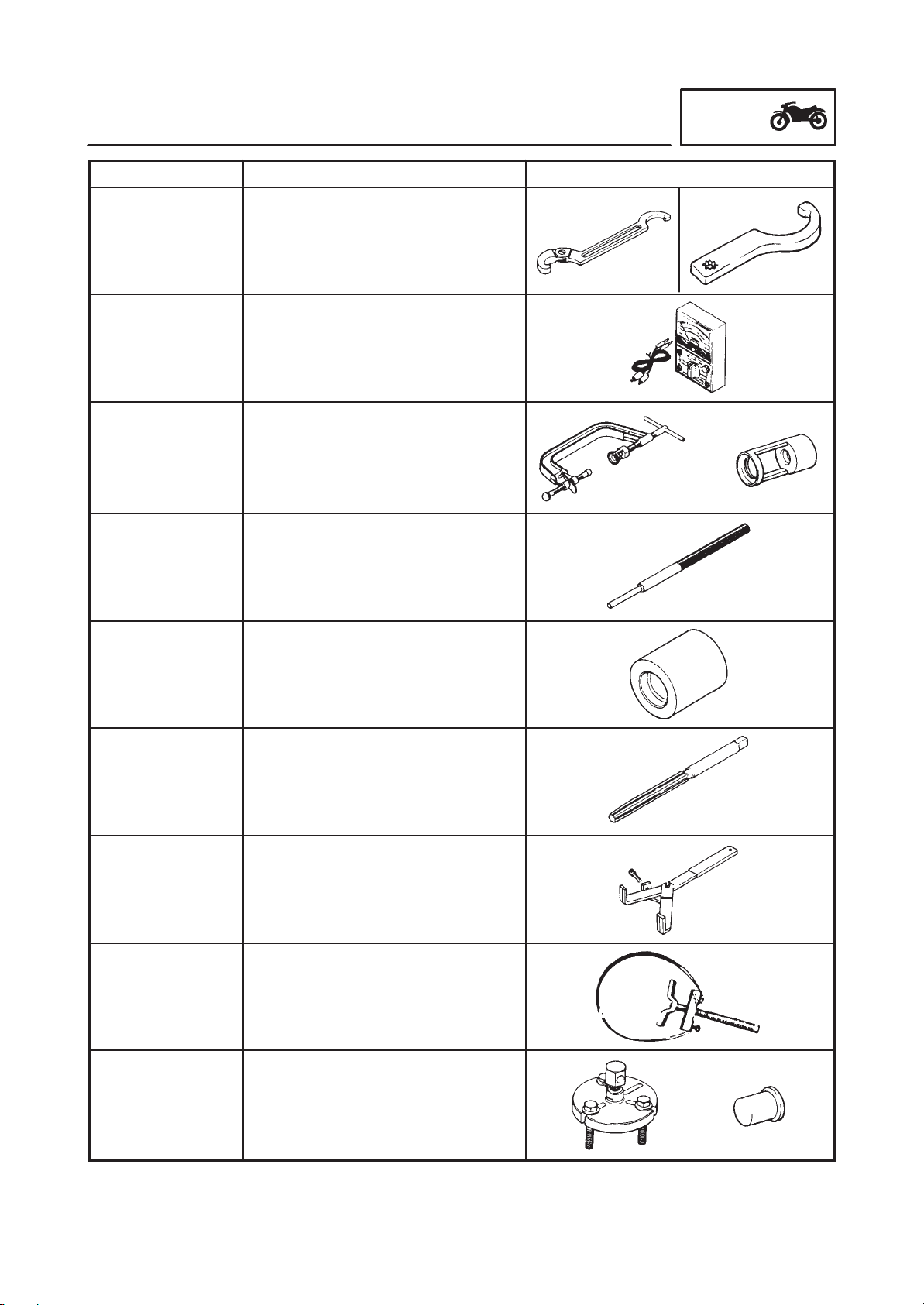
YU-01268
90890-01268
YU-33975
90890-01403
Ring nut wrench
This tool is needed to loosen and
tighten the steering stem ring nut.
YU-03112
90890-03112
Pocket tester
This instrument is needed for check-
ing the electrical system.
Compressor
YM-04019
90890-04019
Adapter
YM-01253-1
90890-04114
Valve spring compressor/adapter
These tools are needed to remove
and install the valve assemblies.
YM-4064-A
90890-04064
Valve guide remover (6.0 mm)
This tool is needed to remove and
install the valve guide.
YM-04065-A
90890-04065
Vale guide installer (6.0 mm)
This tool is needed to install the
valve guide.
YM-04066
90890-04066
Valve guide reamer (6.0 mm)
This tool is needed to rebore the
new valve guide.
YM-91042
90890-04085
Universal clutch holder
This tool is needed to hold the clutch
when removing or installing the
clutch boss nut.
YS-01880
90890-01701
Sheave holder
This tool is needed to hold the rotor
when removing or installing the rotor
bolt.
Puller
YU-33270
90890-01362
Adapter
YM-33282
90890-04089
Flywheel puller/adapter
These tools are needed to remove
the rotor.
1-18
SPECIAL TOOLS
GEN
INFO
Tool No. Tool name/Usage Illustration
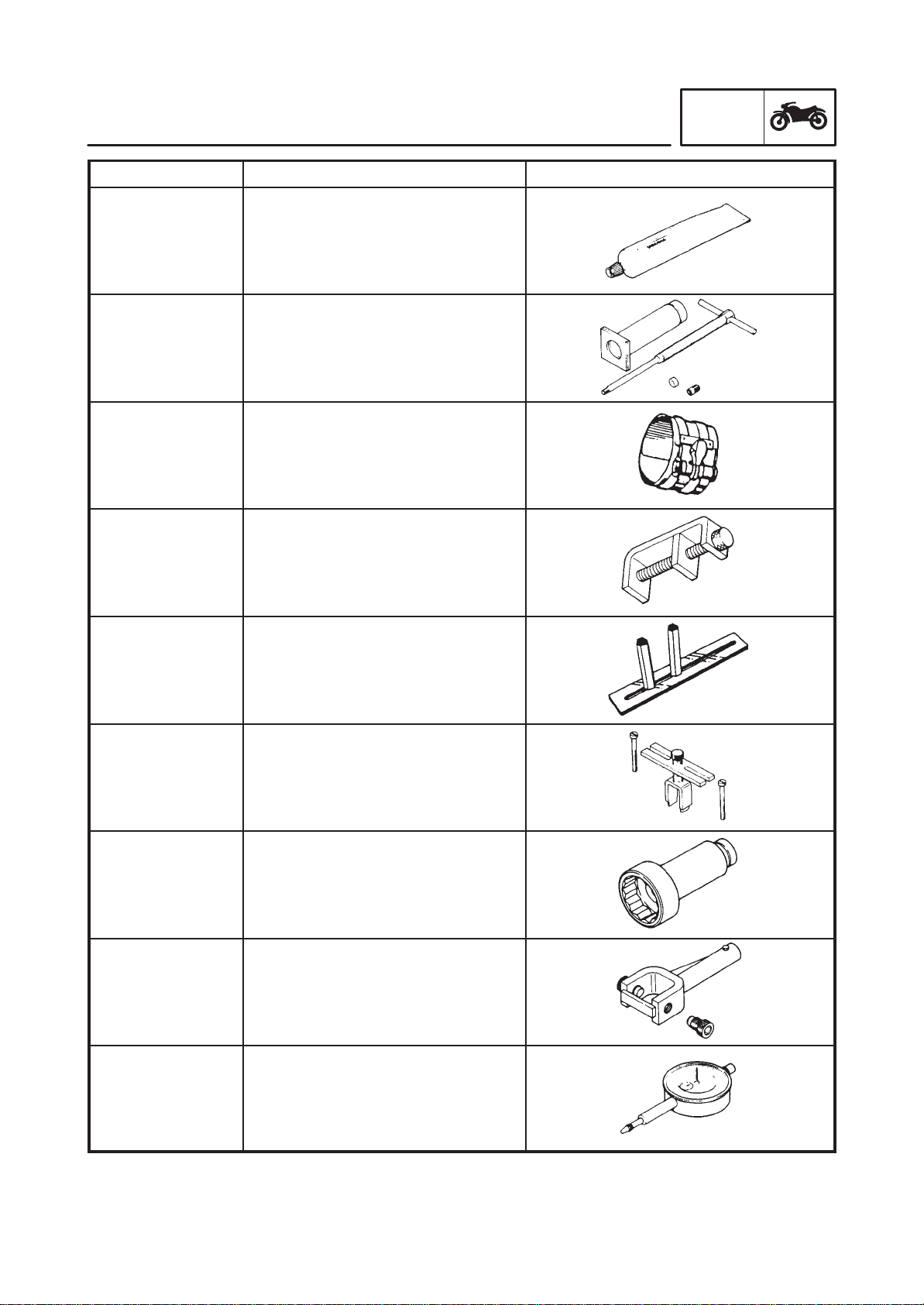
ACC-1100-15-01
90890-85505
Quick gasket
Yamaha Bond No.1215
This sealant (bond) is used on
crankcase mating surfaces, etc.
YU-01304
90890-01304
Piston pin puller
This tool is used to remove the pis-
ton pin.
YM-8037
90890-05158
Piston ring compressor
This tool is used to compress the
piston rings when installing the pis-
ton into the cylinder.
YM-33286
90890-04090
Damper spring compressor
This tool is needed when removing
or installing the damper spring.
YM-33222
Middle drive gear holder
This tool is needed to remove and
install the middle drive pinion gear.
This tool is also used for the gear
backlash adjustment.
90890-04080
Middle drive gear holder
This tool is needed for the gear
backlash adjustment.
YM-04054
90890-04054
Offset wrench (55 mm)
This tool is needed when removing
or installing the middle drive gear
nut.
YM-04062
90890-04062
Universal joint holder
This tool is needed when removing
or installing the driven pinion gear
nut.
YU-03097
90890-03097
Dial gauge
This tool is used to measure the
middle gear backlash.
1-19
SPECIAL TOOLS
GEN
INFO
Tool No. Tool name/Usage Illustration
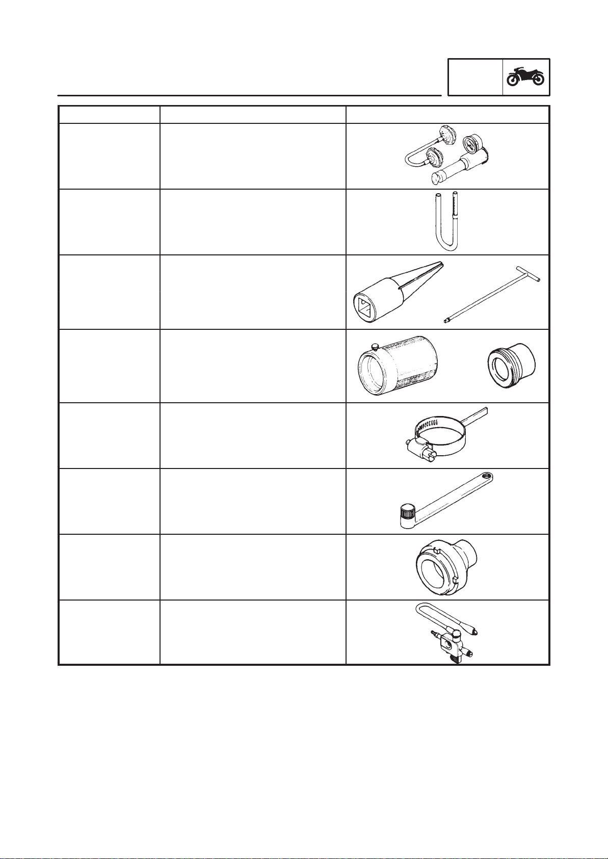
Tester
YU-24460-01
90890-01325
Adapter
YU-33984
Radiator cap tester/adapter
This tester and its adapter are need-
ed for checking the cooling system.
YM-01312-A
90890-01312
Fuel level gauge
This gauge is used to measure the
fuel level in the float chamber.
Rod holder
YM-01300-1
90890-01294
Damper rod holder/T-handle
T-handle
YM-01326
90890-01326
These
tools
are
needed
to
loosen
and tighten the damper rod holding
bolt.
Weight
YM-33963
90890-01367
Adapter
YM-8020
90890-01374
Fork seal driver weight/adapter
These tools are needed when instal-
ling the slide metal, oil seal and dust
seal into the fork.
YM-01230
90890-01230
Final gear backlash band
This tool is needed when measuring
final gear backlash.
YM-01229
90890-01229
Coupling gear/middle shaft tool
This tool is needed when removing
or installing the coupling gear nut.
YM-04050
90890-04050
Bearing retainer wrench
This tool is needed when removing
or installing the final drive shaft
bearing.
YM-34487
90890-06754
Dynamic spark tester
Ignition checker
Loading...