


 Loading...
POWER AMPLIFIER


 /
/


SERVICE MANUAL
XP7000
XP5000
■ CONTENTS


 ECF
ECF
This document is printed on chlorine free (ECF) paper.
PA 011812
XP7000: 200512-281400
XP5000: 200512-239400
SPECIFICATIONS ............................................... |
3/5 |
MONITOR/REMOTE PIN LAYOUT |
|
MONITOR/REMOTE ................................. |
4/6 |
DIMENSIONS ........................................................... |
7 |
PERFOMANCE GRAPHS .......................................... |
7 |
PANEL LAYOUT ...................................... |
8 |
CIRCUIT BOARD LAYOUT & WIRING |
|
.............................................. |
10 |
DISASSEMBLY PROCEDURES .......................... |
16 |
IC BLOCK DIAGRAMIC ................................... |
23 |
CIRCUIT BOARDS ........................................ |
24 |
INSPECTIONS ....................................................... |
36/42 |
PS CIRCUIT BOARD REPAIR GUIDE |
|
PS ............................................... |
48/56 |
PARTS LIST |
|
IC & DIODE OUTSIDE FIGURE |
|
BLOCK DIAGRAM |
|
WIRING DIAGRAM |
|
CIRCUIT DIAGRAM |
|
HAMAMATSU, JAPAN
Copyright (c) Yamaha Corporation. All rights reserved. 


 06.01
06.01

XP7000/XP5000
IMPORTANT NOTICE
This manual has been provided for the use of authorized Yamaha Retailers and their service personnel. It has been assumed that basic service procedures inherent to the industry, and more specifically Yamaha Products, are already known and under stood by the users, and have therefore not been restated.
WARNING: Failure to follow appropriate service and safety procedures when servicing this product may result in per-sonal injury, destruction of expensive components and failure of the product to perform as specified. For these reasons, we advise all Yamaha product owners that all service required should be performed by an authorized Yamaha Retailer or the appointed service representative.
IMPORTANT: This presentation or sale of this manual to any individual or firm does not constitute authorization, certification, recognition of any applicable technical capabilities, or establish a principal-agent relationship of any form.
The data provided is believed to be accurate and applicable to the unit (s) indicated on the cover. The research engineering, and service departments of Yamaha are continually striving to improve Yamaha products. Modifications are, therefore, inevitable and changes in specification are subject to change without notice or obligation to retrofit. Should any discrepancy appear to exist, please contact the distributor’s Service Division.
WARNING: Static discharges can destroy expensive components. Discharge any static electricity your body may have accumulated by grounding yourself to the ground bus in the unit (heavy gauge black wiresonnect to this bus).
IMPORTANT: Turn the unit OFF during disassembly and parts replacement. Recheck all work before you apply power to the unit.
WARNING: CHEMICAL CONTENT NOTICE!
The solder used in the production of this product contains LEAD. In addition, other electrical/electronic and/or plastic (Where applicable) components may also contain traces of chemicals found by the California Health and Welfare Agency (and possibly other entities) to cause cancer and/or birth defects or other reproductive harm.
DO NOT PLACE SOLDER, ELECTRICAL/ELECTRONIC OR PLASTIC COMPONENTS IN YOUR MOUTH FOR ANY REASON WHAT SO EVER!
Avoid prolonged, unprotected contact between solder and your skin! When soldering, do not inhale solder fumes or expose eyes to solder/flux vapor!
If you come in contact with solder or components located inside the enclosure of this product, wash your hands before handling food.
IMPORTANT NOTICE FOR THE UNITED KINGDOM
Connecting the Plug and Cord
WARNING: THIS APPARATUS MUST BE EARTHED
IMPORTANT. The wires in this mains lead are coloured in accordance with the following code: GREEN-AND-YELLOW: EARTH
BLUE: NEUTRAL
BROWN: LIVE
As the colours of the wires in the mains lead of this apparatus may not correspond with the coloured markings identifying the terminals in your plug proceed as follows:
The wire which is coloured GREEN-and-YELLOW must be connected to the terminal in the plug which is marked by the letter E or by the safety earth symbol  or colored GREEN or GREEN-and-YELLOW.
The wire which is coloured BLUE must be connected to the terminal which is marked with the letter N or coloured BLACK.
The wire which is coloured BROWN must be connected to the terminal which is marked with the letter L or coloured RED.
• This applies only to products distributed by Yamaha-Kemble Music (U.K.) Ltd. (3 wires)
■ WARNING
Components having special characteristics are marked  and must be replaced with parts having specification equal to those originally installed.

2
|
|
|
|
|
|
|
|
|
|
|
|
|
|
XP7000/XP5000 |
|
■ SPECIFICATIONS |
|
|
|
|
|
|
|
|
|
|
|
|
|
||
|
|
|
|
|
|
|
|
|
|
|
|
|
|
|
|
|
|
XP7000 |
|
|
|
|
|
120V (U/T) |
230V (H/B/K/O) |
|
240V (A) |
|
|||
Output Power |
1kHz |
8ohms/STEREO |
|
|
750W + 750W |
750W + 750W |
|
750W + 750W |
|
||||||
|
THD+N=1% |
4ohms/STEREO |
|
|
1100W + 1100W |
1100W + 1100W |
|
1100W + 1100W |
|
||||||
|
|
|
8ohms/BRIDGE |
|
|
2200W |
|
2200W |
|
2200W |
|
||||
|
20Hz - 20kHz |
8ohms/STEREO |
|
|
700W + 700W |
650W + 650W |
|
700W + 700W |
|
||||||
|
THD+N=1% |
4ohms/STEREO |
|
MIN |
950W + 950W |
950W + 950W |
|
950W + 950W |
|
||||||
|
|
|
70V/STEREORL=8ohms |
|
625W + 625W |
625W + 625W |
|
625W + 625W |
|
||||||
|
|
|
8ohms/BRIDGE |
|
|
1900W |
|
1900W |
|
1900W |
|
||||
|
1kHz |
2ohms/STEREO |
|
|
1600W + 1600W |
1600W + 1600W |
|
1600W + 1600W |
|
||||||
|
20mS nonclip |
4ohms/BRIDGE |
|
|
3200W |
|
3200W |
|
3200W |
|
|||||
SN Ratio |
20Hz - 20kHz |
(DIN AUDIO) |
|
|
MIN |
|
|
|
104dB |
|
|
|
|||
Power Consumption |
Standby/Idle |
|
|
|
|
|
|
|
|
5W/35W |
|
|
|
||
|
1/8 (4ohms/Pink noise) |
|
|
|
|
|
650W |
|
650W |
|
650W |
|
|||
|
|
|
|
|
|
|
|
|
|
|
|
|
|
|
|
|
|
XP5000 |
|
|
|
|
|
120V (U/T) |
230V (H/B/K/O) |
|
240V (A) |
|
|||
Output Power |
1kHz |
8ohms/STEREO |
|
|
525W + 525W |
525W + 525W |
|
525W + 525W |
|
||||||
|
THD+N=1% |
4ohms/STEREO |
|
|
750W + 750W |
750W + 750W |
|
750W + 750W |
|
||||||
|
|
|
8ohms/BRIDGE |
|
|
1500W |
|
1500W |
|
1500W |
|
||||
|
20Hz - 20kHz |
8ohms/STEREO |
|
MIN |
500W + 500W |
500W + 500W |
|
500W + 500W |
|
||||||
|
THD+N=1% |
4ohms/STEREO |
|
700W + 700W |
700W + 700W |
|
700W + 700W |
|
|||||||
|
|
|
|
|
|||||||||||
|
|
|
8ohms/BRIDGE |
|
|
1400W |
|
1400W |
|
1400W |
|
||||
|
1kHz |
2ohms/STEREO |
|
|
1300W + 1300W |
1300W + 1300W |
|
1300W + 1300W |
|
||||||
|
20mS nonclip |
4ohms/BRIDGE |
|
|
2600W |
|
2600W |
|
2600W |
|
|||||
SN Ratio |
20Hz - 20kHz |
(DIN AUDIO) |
|
|
MIN |
|
|
|
103dB |
|
|
|
|||
Power Consumption |
Standby/Idle |
|
|
|
|
|
|
|
|
5W/35W |
|
|
|
||
|
1/8 (4ohms/Pink noise) |
|
|
|
|
|
500W |
|
500W |
|
500W |
|
|||
|
|
|
|
|
|
|
|
|
|
|
|
|
|
|
|
|
|
All Models |
|
|
|
|
|
|
|
|
|
|
|
|
|
Power Bandwidth |
|
Half Power, THD+N=0.5% |
|
MIN |
10Hz - 40kHz |
|
|
|
|
|
|
||||
THD+N |
|
20Hz - 20kHz, Half Power |
|
MAX |
0.1% |
|
|
|
|
|
|
|
|
||
Intermoduration Distortion 60Hz:7kHz, 4:1, Half Power |
|
MAX |
0.1% |
|
|
|
|
|
|
|
|
||||
Frequency Response |
|
RL=8ohms, Po=1W, HPF=OFF |
|
MAX |
0dB |
|
|
|
|
|
|
|
|
||
|
|
20Hz - 50kHz |
|
|
TYP |
0dB |
|
|
|
|
|
|
|
|
|
|
|
|
|
|
MIN |
-1dB |
|
|
|
|
|
|
|
|
|
Channel Separation |
|
Half Power, RL=8ohms, 1kHz, |
|
MIN |
70dB |
|
|
|
|
|
|
|
|
||
|
|
Att. Max, input 600ohms shunt |
|
|
|
|
|
|
|
|
|
||||
|
|
|
|
|
|
|
|
|
|
|
|
|
|
||
Residual Noise |
|
20Hz - 20kHz, Att. Min, |
|
MAX |
-70dBu |
|
|
|
|
|
|
|
|
||
|
|
(DIN AUDIO) |
|
|
|
|
|
|
|
|
|
|
|||
|
|
|
|
|
|
|
|
|
|
|
|
|
|
|
|
Damping Factor |
|
RL=8ohms, 1kHz |
|
|
MIN |
350 |
|
|
|
|
|
|
|
|
|
Voltage Gain |
|
Att. Max |
|
|
TYP |
Selectable from 32dB or 26dB (or +4dBu input sensitivity) by GAIN switch |
|
||||||||
Input Sensitivity (dBu) |
|
|
|
|
|
|
|
XP7000 |
|
|
|
XP5000 |
|
||
|
|
Switch Position |
|
|
+4dBu |
|
|
+4 |
|
|
|
|
+4 |
|
|
|
|
|
|
|
26dB |
|
|
+13.7 |
|
|
|
|
+12.2 |
|
|
|
|
|
|
|
36dB |
|
|
+7.7 |
|
|
|
|
+6.2 |
|
|
Maximum Input Voltage |
|
|
|
|
MIN |
+22dBu |
|
|
|
|
|
|
|
|
|
Input Impedance |
|
|
|
|
TYP |
20kohms (balanced), 10kohms (unbalanced) |
|
|
|
||||||
Controls |
|
Front Panel |
|
|
|
POWER switch (push on/push off) |
|
|
|
||||||
|
|
|
|
|
|
Attenuator (31-position) x 2 |
|
|
|
|
|
|
|||
|
|
Rear Panel |
|
|
|
MODE switch (STEREO/BRIDGE/PARALLEL) x 1 |
|
|
|
||||||
|
|
|
|
|
|
HPF switch (20Hz/55Hz/OFF 12dB/oct) x 2 |
|
|
|
||||||
|
|
|
|
|
|
GAIN switch (32dB/26dB/+4dBu) x 1 |
|
|
|
||||||
Connectors |
|
Input |
|
|
|
XLR-3-31 type/ch |
|
|
|
|
|
|
|||
|
|
|
|
|
|
Euroblock connector (balanced) /ch |
|
|
|
||||||
|
|
Output |
|
|
|
SPEAKON /ch, 5 way binding post x 1 |
|
|
|
||||||
|
|
MONITOR/REMOTE |
|
D-Sub 15 pin x 1 |
|
|
|
|
|
|
|||||
Indicators |
|
POWER/STANDBY |
|
x 1 (Green/Orange) |
|
|
|
|
|
|
|||||
|
|
SIGNAL |
|
|
|
x 2 (Green) |
|
|
|
|
|
|
|||
|
|
CLIP |
|
|
|
x 2 (Red) |
|
|
|
|
|
|
|
|
|
|
|
PROTECTION |
|
|
|
x 1 (Red) |
|
|
|
|
|
|
|
|
|
|
|
TEMP |
|
|
|
x 1 (Red) heatsink temp ≥ 85°C |
|
|
|
|
|
|
|||
Load Protection |
|
|
|
|
|
POWER switch on/off mute |
|
|
|
|
|
|
|||
|
|
|
|
|
|
DC-fault: power supply shutdown |
|
|
|
||||||
|
|
|
|
|
|
Clip limiting: THD ≥ 0.5% |
|
|
|
|
|
|
|||
Amplifier Protection |
|
|
|
|
|
Thermal: cuts the output (heatsink temp ≥ 90°C) |
|
|
|
||||||
|
|
|
|
|
|
VI limiter (RL ≤ 1ohm) |
|
|
|
|
|
|
|||
Power Supply Protection |
|
|
|
Thermal: power supply shutdown (heatsink temp ≥ 100°C) |
|
||||||||||
Cooling |
|
|
|
|
|
Variable-speed fan x 2 |
|
|
|
|
|
|
|||
|
|
|
|
|
|
Fan stops at heatsink temp ≤ 55°C |
|
|
|
||||||
Power Requirements |
|
|
|
|
|
|
|
U/T |
|
H/B/K/O |
|
|
A |
|
|
|
|
|
|
|
|
|
120V, 60Hz |
|
230V, 50Hz |
|
|
240V, 50Hz |
|
||
3

XP7000/XP5000
All Models
Dimensions (W x H x D) |
480 x 88 x 456 mm |
|
Weight |
XP7000 |
XP5000 |
|
14 kg |
14 kg |
Accessories |
Security cover (with a hex wrench), Owner’s Manual |
|
0dBu=0.775Vrms, Half Power=1/2 Output Power (3dB below rated power)
■ MONITOR/REMOTE PIN LAYOUT
Pin No. |
|
Signal |
Description |
|
1 |
GND |
|
|
|
2 |
REMOTE CONTROL |
|
STANDBY |
STANDBY Control: Supply 5VDC, 5mADC |
3 |
MONITOR |
|
MODEL ID |
1.0kohms (Impedance to GND) |
4 |
REMOTE CONTROL |
|
NC |
|
5 |
|
|
NC |
|
6 |
|
|
MUTE CH B |
MUTE Control: Connected to GND, +5V, 1mA |
7 |
|
|
MUTE CH A |
|
8 |
MONITOR |
|
NC |
|
9 |
|
|
NC |
|
10 |
|
|
PROTECT STATUS CH B |
PROTECTION Off/Output On: +5VDC, Zo=270ohms |
11 |
|
|
PROTECT STATUS CH A |
PROTECTION On/Output Off: 0VDC, Zo=High |
12 |
|
|
NC |
|
13 |
|
|
NC |
|
14 |
|
|
OUTPUT LEVEL CH B |
+4dBu (-27.2dB of Speaker Output Level) at 100W/8ohms, RL=7.5kohms, |
15 |
|
|
OUTPUT LEVEL CH A |
Zo=300ohms |
4

XP7000/XP5000
■
|
XP7000 |
|
|
|
100V J |
||
|
1kHz |
|
8Ω/STEREO |
|
750W |
+ |
750W |
|
THD+N=1% |
|
4Ω/STEREO |
|
1100W |
+ |
1100W |
|
|
|
8Ω/BRIDGE |
|
2200W |
||
|
20Hz 20kHz |
|
8Ω/STEREO |
|
700W |
+ |
700W |
|
THD+N=1% |
|
4Ω/STEREO |
MIN |
930W |
+ |
930W |
|
|
|
70 V/STEREO RL=8Ω |
|
625W |
+ |
625W |
|
|
|
8Ω/BRIDGE |
|
1860W |
||
|
1kHz |
|
2Ω/STEREO |
|
1400W |
+ |
1400W |
|
20mS nonclip |
|
4Ω/BRIDGE |
|
2800W |
||
SN |
20Hz 20kHz |
DIN AUDIO |
MIN |
104dB |
|||
|
Standby/Idle |
|
|
|
5W/35W |
||
|
1/8 4Ω/ |
|
650W |
||||
|
XP5000 |
|
|
|
100V J |
||
|
1kHz |
|
8Ω/STEREO |
|
525W |
+ |
525W |
|
THD+N=1% |
|
4Ω/STEREO |
|
750W |
+ |
750W |
|
|
|
8Ω/BRIDGE |
|
1500W |
||
|
20Hz 20kHz |
|
8Ω/STEREO |
MIN |
500W |
+ |
500W |
|
THD+N=1% |
|
4Ω/STEREO |
700W |
+ |
700W |
|
|
|
|
|||||
|
|
|
8Ω/BRIDGE |
|
1400W |
||
|
1kHz |
|
2Ω/STEREO |
|
1050W |
+ |
1050W |
|
20mS nonclip |
|
4Ω/BRIDGE |
|
2100W |
||
SN |
20Hz 20kHz |
DIN AUDIO |
MIN |
103dB |
|||
|
Standby/Idle |
|
|
|
5W/35W |
||
|
1/8 4Ω/ |
|
500W |
||||
All Models
|
|
Half Power THD+N=0.5% |
MIN |
10Hz 40kHz |
|
|
THD+N |
|
20Hz 20kHz Half Power |
MAX |
0.1% |
|
|
|
|
60Hz:7kHz 4:1 Half Power |
MAX |
0.1% |
|
|
|
|
RL=8Ω Po=1W HPF=OFF |
MAX |
0dB |
|
|
|
|
20Hz 50kHz |
TYP |
0dB |
|
|
|
|
|
MIN |
-1dB |
|
|
Half Power RL=8Ω 1kHz |
MIN |
70dB |
|
|||
|
|
600Ω |
|
|||
|
|
20Hz 20kHz |
MAX |
-70dBu |
|
|
|
DIN AUDIO |
|
|
|
|
|
|
|
RL=8Ω 1kHz |
MIN |
350 |
|
|
|
|
|
TYP |
32dB 26dB +4dBu GAIN |
||
dBu |
|
|
|
XP7000 |
|
XP5000 |
|
|
|
+4dBu |
+4 |
|
+4 |
|
|
|
26dB |
+13.7 |
|
+12.2 |
|
|
|
36dB |
+7.7 |
|
+6.2 |
|
|
|
MIN |
+22dBu |
|
|
|
|
|
TYP |
20kΩ 10kΩ |
|
|
|
|
|
|
POWER / |
|
|
|
|
|
|
31 x 2 |
|
|
|
|
|
|
MODE STEREO/BRIDGE/PARALLEL x 1 |
|
|
|
|
|
|
HPF 20Hz/55Hz/OFF 12dB/oct x 2 |
|
|
|
|
|
|
GAIN 32dB/26dB/+4dBu x 1 |
|
|
|
|
|
|
XLR-3-31 |
|
|
|
|
|
|
|
||
|
|
|
|
5 x 1 |
||
|
|
MONITOR/REMOTE |
|
D-Sub 15 x 1 |
|
|
|
|
POWER/STANDBY |
|
x 1 / |
|
|
|
|
SIGNAL |
|
x 2 |
|
|
|
|
CLIP |
|
x 2 |
|
|
|
|
PROTECTION |
|
x 1 |
|
|
|
|
TEMP |
|
x 1 85 |
|
|
|
|
|
|
POWER / |
|
|
|
|
|
|
DC |
|
|
|
|
|
|
THD 0.5% |
|
|
|
|
|
|
90 |
|
|
|
|
|
|
VI RL 1Ω |
|
|
|
|
|
|
100 |
||
|
|
|
|
x 2 |
|
|
|
|
|
|
55 |
|
|
|
|
|
|
100V 50/60Hz |
|
|
5

XP7000/XP5000
All Models
W x H x D |
480 x 88 x 456 mm |
|
|
XP7000 |
XP5000 |
|
14 kg |
14 kg |
|
6 |
|
0dBu=0.775Vrms, Half Power=1/2 Output Power (3dB below rated power)
■ MONITOR/REMOTE
|
|
|
|
|
1 |
GND |
|
|
|
2 |
REMOTE CONTROL |
|
STANDBY |
STANDBY Control Supply 5VDC 5mADC |
3 |
MONITOR |
|
MODEL ID |
1.0kΩ Impedance to GND |
4 |
REMOTE CONTROL |
|
NC |
|
5 |
|
|
NC |
|
6 |
|
|
MUTE CH B |
MUTE Control Connected to GND +5V 1mA |
7 |
|
|
MUTE CH A |
|
8 |
MONITOR |
|
NC |
|
9 |
|
|
NC |
|
10 |
|
|
PROTECT STATUS CH B |
PROTECTION Off/Output On +5VDC Zo=270Ω |
11 |
|
|
PROTECT STATUS CH A |
PROTECTION On/Output Off 0VDC Zo=High |
12 |
|
|
NC |
|
13 |
|
|
NC |
|
14 |
|
|
OUTPUT LEVEL CH B |
+4dBu -27.2dB of Speaker Output Level at 100W/8Ω RL=7.5kΩ |
15 |
|
|
OUTPUT LEVEL CH A |
Zo=300Ω |
6

■ DIMENSIONS
30
374.5 |
456 |
46 |
|
5.5 |
30 |
362 |
30 |
|
480 |
|
88
■ PERFOMANCE GRAPHS
• XP7000 |
|
|
|
|
|
• XP5000 |
|
|
||||
|
|
|
|
|
|
Mode:STEREO |
|
|
|
|
||
|
|
|
|
|
|
Both ch Driven |
|
|
|
|
||
|
10000 |
|
|
|
|
RL=4 |
Ω, f=1 kHz |
|
10000 |
|
|
|
[W] |
|
|
|
|
|
|
|
[W] |
|
|
||
|
|
|
|
|
|
|
|
|
||||
1000 |
|
|
|
|
|
|
|
1000 |
|
|
||
Consumption |
|
|
|
|
|
|
|
Consumption |
|
|
||
100 |
|
|
|
|
|
|
|
100 |
|
|
||
|
|
|
|
|
|
|
|
|
|
|
||
Power |
10 |
|
|
|
|
|
|
|
Power |
10 |
|
|
|
|
|
|
|
|
|
|
|
|
|
||
|
1 |
|
|
|
|
|
|
|
|
1 |
|
|
|
1 |
10 |
100 |
1000 |
10000 |
|
1 |
|||||
Output Power [W]
XP7000/XP5000
Unit: mm
mm
Mode:STEREO
Both ch Driven
RL=4 Ω, f=1 kHz
10 |
100 |
1000 |
Output Power [W]
7

XP7000/XP5000
■ PANEL LAYOUT
• Front Panel
2 4
|
7 |
1 |
3 |
|
5 6 |
7 |
1 |
[POWER] switch and indicator |
|
|
1 POWER / |
||
2 |
[TEMP] indicator |
|
|
2 TEMP |
|
|
3 |
[PROTECTION] indicator |
|
|
3 PROTECTION |
||
4 |
[CLIP] indicator |
|
|
4 CLIP |
|
|
5 |
[SIGNAL] indicator |
|
|
5 SIGNAL |
|
|
6 Volume control knobs |
|
|
6 |
|
|
|
7 Air intakes |
|
|
7 |
|
|
|
8

XP7000/XP5000
• Rear Panel
4 3 5 6 7
|
1 |
|
|
|
|
|
|
|
|
|
|
|
|
|
|
|
|
|
|
|
|
|
|
|
|
|
|
|
|
|
|
|
|
|
|
|
|
|
|
|
|
|
|
|
|
|
|
|
|
|
|
|
|
|
|
|
|
|
|
|
|
|
|
|
|
|
|
|
|
|
|
|
|
|
|
|
|
|
|
|
8 |
|
|||||||
|
2 |
7 |
|
||||||
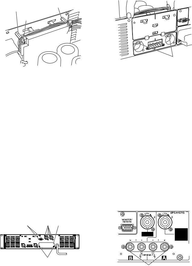
1 XLR inputs connectors (One pair for each channel) |
1 XLR A B |
||||||||
2 Euroblock inputs connector |
|
|
|
2 |
|||||
3 |
[HPF] switches (One pair for each channel) |
|
|
|
3 HPF A B |
||||
4 |
[GAIN] switch |
|
|
|
4 GAIN |
||||
5 |
[MODE] switch |
|
|
|
5 MODE |
||||
6 |
[MONITOR/REMOTE] terminal |
|
|
|
6 MONITOR/REMOTE |
||||
7 |
[SPEAKERS] terminals |
|
|
|
7 SPEAKERS |
||||
8 GND terminal |
|
|
|
8 GND |
|
|
|
||
9

XP7000/XP5000
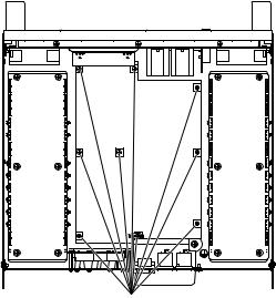
■ CIRCUIT BOARD LAYOUT&WIRING
PAH |
PSW |
IO 3/4 |
IO 2/4 |
IO 1/4 |
IO 4/4 |
PAH |
PS
COIL * |
LED |
VR |
*J/H/B/K/O destinations only.
Rear Panel
IO 1/4 |
IO 3/4 |
IO 2/4 |
IO 4/4 |
The figure which looked at the front panel from the inner side
LED
Front Panel |
PSW |
|
LED
↑ Bottom
↓Top
↑Top
↓ Bottom
10
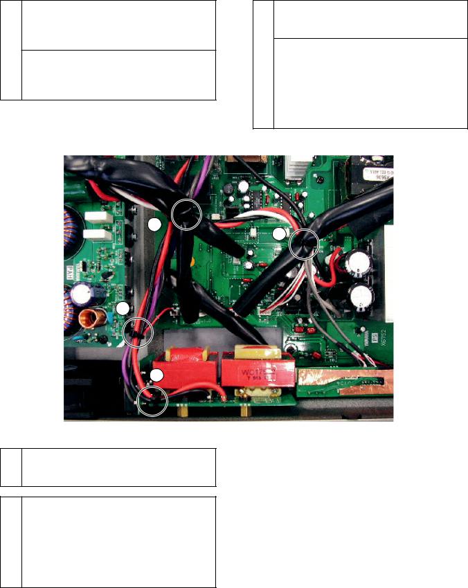
• Whole wiring drawing
See page 12
This point has a wire harness tie.
2
1 |
See page 12
7 |
See page 13
8 |
See page 13
See page 13
3 |
XP7000/XP5000
See page 13 |
See page 13 |
4 |
5 |
6 |
See page 13
11 |
10 |
See page |
See page |
14, 15 |
14, 15 |
9 |
12 |
See page |
See page |
14, 15 |
14, 15 |
Tube 18: BLACK (CH00440)
*Not available as service parts.
•Detail drawing IO 1/4IO 1/4
*Attach connector assembly ATT (WD359600) and connector assembly SIG (WF442900) as follows before attaching IO 1/4 circuit board to main chassis.
IO 1/4 ATT WD359600 SIG WF442900
Connector assembly ATT (WD359600)
Connector assembly SIG (WF442900)
11

XP7000/XP5000
•Detail drawing IO 3/4 IO 3/4
*Attach earth film (WG463400) to speaker terminal SP301 and SP302 as follows.
WG463400 SP301 SP302
•Detail drawing IO 4/4 IO 4/4
*Attach earth film (WD494300) as follows and attached it to speaker terminal SP303.
WD494300 SP303
• Detail drawing 1 2 1 2
* Tie the following connector assemblies.
2 |
|
|
|
1 |
WF442700, WF442800, WF442900 |
||
|
|||
|
|
|
|
|
|
|
|
1 |
|
WF442800, WF442900, WD360100 (W305) |
|
|
|
||
|
|
WD360100 (W305) should be crossed under the |
|
|
2 |
others. |
|
|
|
WD360100 W305 |
|
|
|
|
|
|
|
|
12

• Detail drawing 3 4 5 3 4 5
4
5
3
Keep connector assembly WD360900 (W306) as far away from IO 1/4 circuit board as possible.
WD360900 W306 IO 1/4
• Detail drawing 6 6
6
XP7000/XP5000
*Tie the following connector assemblies.
Connector assembly WF442900 is tied to IO 1/4 circuit board with cord holder.
Connector assembly is placed on a compornent side of the circuit board.
3Each tie is laced through the hole on the circuit
4board and shield paper (WG46350).
WF442900 IO 1/4 WG46350
5WD359600, WF442700, WF442900
*WG46350 is not available as service parts.
WG46350
*Tie the following connector assemblies.
WD359600, WF442900, WF442700, WD360900
(W306), WD360300 (W406), WD360400 (W407),
WD360500 (W408)
WD359600 and WF442900 are laced through tube
6(CH00440).
WD359600 WF442900 CH00440
WD360900 (W306) should be crossed under the others.
WD360900 W306
Connector assemblies WD360300 (W406), WD360400 (W407) and WD360500 (W408) are twisted more than two rotations.
WD360300 W306 WD360400 W407 WD360500 W408 2
Keep three connector assemblies (WD359600, WF442900, WF442700) as far away from transformer (T402) as possible.
3 WD359600 WF442900 WF442700T402
*CH00440 is not available as service parts.
CH00440
• Detail drawing 7 8 7 8
* Tie the following connector assemblies.
7 |
|
|
|
7 |
WD361000 (W701), WD361100 (W702), WF444300 |
||
|
|||
|
|
(W304), WD360100 (W305) |
|
|
8 |
WD360000 (W401), WD360100(W402), |
|
8 |
|
WD360200 (W403), WF442700, WF442800 |
13
XP7000/XP5000
•Detail drawing 9 0 A B 9 0 A B
*Tie the following connector assemblies.
WD360000 (W401), WD360100 (W402), WD360200
(W403), WF443200 (W309), WD361000 (W701),
WD361100 (W702), WF443100 x 2 (W307, W308),
9WF442700, WF442800
WF443100 x 2 (W307, W308) and WF443200 (W309) should be crossed under the others.
WF443100 x 2 W307 W308 WF443200W309
9
10
11
WF443100 x 2 (W307, W308), WF443200 (W309),
0WD361000 (W701), WD361100 (W702), FAN Lead Wiring
Connector assemblies WD361000 (W701) and
WD361100 (W702) are tied to COIL circuit board with cord holder (J/H/B/K/O destinations). The cord holder is laced through the hole on the circuit board.
A WD361000 W701 WD361100 W702J/H/B/K/O COIL
WD359600, WF442900, WF442700, WD360000
(W401), WD360200 (W403), WD360100 x 2 (W305,
W402)
WD359600, WF442900 and WF442700 shoud be crossed over the others.
BWD359600 WF442900 WF442700
WD360100 (W305) should be crossed under the others.
WD360100 W305
12
14

XP7000/XP5000
Connector assemblies WD360000 (W401), WD360100 (W402), and WD360200 (W403) are twisted more than two rotations.
WD360000 W401 WD360100 W402 WD360200 W403 2
Connector assemblies WD361000 (W701) and WD361100 (W702) are twisted more than two rotations.
WD361000 W701 WD361100 W702
3
Connector assembly WF872900 (W310) is located on the left side of WF442700 connected to CN411 and crossed under WF442700 connected to CN412.
WF872900 W310 CN411 WF442700 CN412
WF442700
Connector assemblies WD361000 (W701) and WD361100 (W702) are tied to COIL circuit board with cord holder. The cord holder is laced through the hole on the circuit board.
WD361000 W701 WD361100 W702 COIL
15

XP7000/XP5000
■ DISASSEMBLY PROCEDURES
1. |
Rack Angle (Time required: about 1 min.) |
|
1. |
1 |
|
1-1 |
Remove the three (3) screws marked [470] for each side. |
1-1 |
470 3 |
||
|
The rack angle can then be removed. (Fig. 1) |
|
|
Fig. 1 |
|
2. |
Top Cover (Time required: about 2 min.) |
|
2. |
2 |
|
2-1 |
Remove the eleven (11) screws marked [530]. |
|
2-1 |
530 11 |
|
|
The top cover can then be removed. (Fig. 1) |
|
|
Fig. 1 |
|
|
[470] |
|
|
|
[470] |
|
[530] |
[345] |
[345] [530] |
|
[530] |
[530] |
[530] |
[320][310] [320]
[310]: Pan Head Screw 2.6X6 MFZN2B3 (WE986400) + PAN
[320]: Bonding Tapping Screw-B 3.0X10 MFZN2B3 (WE878000) B + BOND [345]: Bind Head Tapping Screw-S 3.0X6 MFZN2B3 (WE877800) S + BIND [470]: Bind Head Screw 4.0X10 MFZN2B3 (WE980400) + BIND
[530]: Bind Head Screw 4.0X8 MFZN2B3 (WE962000) B + BIND
(Fig. 1)
3. PA Unit (Time required: about 5 min.) |
3. PA 5 |
||
3-1 |
Remove the top cover. (See procedure 2.) |
3-1 |
2 |
3-2 |
Remove the six (6) screws marked [200] for each side |
3-2 |
200 6 PA |
|
from the bottom. The PA units can then be removed. |
|
Fig. 2 |
|
(Fig. 2) |
|
* PA |
|
* Flat washers are attached between the main chassis |
|
200 |
|
and PA unit. Take care not to lose flat washers when |
|
|
|
removing screw marked [200]. |
|
|
[200] |
[200] |
<Bottom View>
[200]: Bind Head Screw 4.0X8 MFZN2B3 (WE962000) B + BIND
(Fig. 2)
16
|
|
|
XP7000/XP5000 |
4. PS Circuit Board (Time required: about 5 min.) |
4. |
PS 5 |
|
4-1 |
Remove the top cover. (See procedure 2.) |
4-1 |
2 |
4-2 |
Remove the nine (9) screws marked [230]. The PS cir- |
4-2 |
230 9 PS Fig. 3 |
|
cuit board can then be removed. (Fig. 3) |
|
|
<Top View>
[230]
[230]: Bind Head Tapping Screw-S 3.0X6 MFZN2W3 (WE877900) S + BIND
(Fig. 3)
5.IO 1/4 Circuit Board (Time required: about 6 min.)
5-1 Remove the top cover. (See procedure 2.)
5-2 Remove the two (2) screws marked [310], the four (4) screws marked [320] and the two (2) screws marked [345]. (Fig. 1)
5-3 Remove the two (2) screws marked [340] to remove the two hexagonal spacers. (Fig. 4)
5-4 Remove the solder of W302B on the IO 1/4 circuit board, or W302A on the IO 2/4 circuit board since the IO 1/4 circuit board and the IO 2/4 circuit board are connected with connector assembly W302. Also remove the solder of W301A on the IO 1/4 circuit board, or W301B on the IO 3/4 circuit board since the IO 1/4 circuit board and the IO 3/4 circuit board are connected with connector assembly W301. The IO 1/4 circuit board can then be removed.
*When reinstalling the IO 1/4 circuit board, let the hooks of the XLR connectors out of the chassis at first, and inserts the jacks or switches into the holes on the chassis. (Fig. 5)
*The IO 1/4 circuit board is not available as service parts individually.
5.IO 1/4 6
5-1 2
5-2 310 2 320 4 345 2Fig. 1
5-3 340 2 6
Fig. 4
5-4 IO 1/4 IO 2/4 W302IO 1/4 W302B IO 2/ 4 W302A IO 3/ 4 W301 IO 1/4W301A IO 3/4 W301B IO 1/4
*IO 1/4
Fig. 5
* IO1/4
6.IO 2/4 Circuit Board (Time required: about 6 min.)
6-1 Remove the top cover. (See procedure 2.)
6-2 Remove the IO 1/4 circuit board. (See procedure 5.) 6-3 Remove the solder of W302A on the IO 2/4 circuit board,
or W302B on the IO 1/4 circuit board since the IO 2/4 circuit board and the IO 1/4 circuit board are connected with connector assembly W302. The IO 2/4 circuit board can then be removed.
*The IO 2/4 circuit board is not available as service parts individually.
6.IO 2/4 6
6-1 2 6-2 IO 1/4 5
6-3 IO 2/4 IO 1/4 W302IO 2/4 W302A IO 1/ 4 W302B IO 2/4
* IO2/4
17
XP7000/XP5000
|
Hexagonal Spacer |
Hexagonal Spacer |
6 |
|
|
6 |
|
[340] |
|
|
[340] |
[340]: Bind Head Tapping Screw-S 3.0X6 MFZN2W3 (WE877900)
S + BIND
(Fig. 4)
7.IO 3/4 Circuit Board (Time required: about 4min.)
7-1 Remove the top cover. (See procedure 2.)
7-2 Remove the two (2) hexagonal locked spacers. (Fig. 6) 7-3 Remove the four (4) screws marked [360]. (Fig. 6)
7-4 Remove the solder of W301B on the IO 3/4 circuit board, or W301A on the IO 1/4 circuit board since the IO 3/4 circuit board and the IO 1/4 circuit board are connected with connector assembly W301. Also remove the solder of W303A on the IO 3/4 circuit board, or W303B on the IO 4/4 circuit board since the IO 3/4 circuit board and the IO 4/4 circuit board are connected with connector assembly W303. The IO 3/4 circuit board can then be removed.
*The IO 3/4 circuit board is not available as service parts individually.
8.IO 4/4 Circuit Board (Time required: about 5 min.)
8-1 Remove the top cover. (See procedure 2.)
8-2 Remove the IO 3/4 circuit board. (See procedure 6.) 8-3 Remove the two (2) screws marked [550].
Remove the speaker terminal cover. (Fig. 6)
8-4 Remove the two (2) screws marked [350]. (Fig. 7)
8-5 Remove the solder of W303B on the IO 4/4 circuit board, or W303A on the IO 3/4 circuit board since the IO 4/4 circuit board and the IO 3/4 circuit board are connected with connector assembly W303. The IO 4/4 circuit board can then be removed.
*The IO 4/4 circuit board is not available as service parts individually.
Hexagonal Locked Spacer |
Speaker Terminal Cover |
6 |
[360] SP |
[550]
[360]: Flat Head Tapping Screw-B 3.0X8 MFZN2B3 (WF266800)
B + FLAT
[550]: Bind Head Tapping Screw-S 3.0X6 MFZN2B3 (WE877800)
S + BIND
(Fig. 6)
Hooks
(Fig. 5)
7.IO 3/4 4
7-1 2 7-2 6 2 Fig. 6 7-3 360 4 Fig. 6
7-4 IO 3/4 IO 1/4 W301IO 3/4 W301B IO 1/ 4 W301A IO 4/ 4 W303 IO 3/4W303A IO 4/4 W303B IO 3/4
* IO3/4
8.IO 4/4 5
8-1 2 8-2 IO 3/4 7
8-3 550 2 SPFig. 6
8-4 350 2 Fig. 7
8-5 IO 4/4 IO 3/4 W303IO 4/4 W303B IO 3/ 4 W303A IO 4/4
* IO4/4
[350]
[350]: Bonding Tapping Screw-B 3.0X10 MFZN2B3 (WE878000)
B + BOND
(Fig. 7)
18

|
|
|
|
|
|
|
|
|
|
XP7000/XP5000 |
|||
9. Front Panel Unit (Time required: about 5 min.) |
9. 5 |
||||||||||||
9-1 Remove the rack angle. (See procedure 1.) |
9-1 |
1 |
|||||||||||
9-2 |
Remove the top cover. (See procedure 2.) |
9-2 |
2 |
||||||||||
9-3 |
Cut cord holder (4 point) of the connector assembly. (Fig. |
9-3 4 |
|||||||||||
|
8) |
|
Fig. 8 |
|
|
|
|
|
|
||||
9-4 |
Remove the six (6) screws marked [450]. (Fig. 9) |
9-4 |
450 6 Fig. 9 |
||||||||||
9-5 |
Draws out the front panel unit. |
9-5 |
|
||||||||||
|
|
<Bottom View> |
[450] |
|
|
|
|||||||
|
|
|
|
|
|
|
|
||||||
|
|
|
|
|
|
|
|
|
|
|
|
|
|
|
|
|
|
|
|
|
|
|
|
|
|
|
|
|
|
|
|
|
|
|
|
|
|
|
|
|
|
|
|
|
|
|
|
|
|
|
|
|
|
|
|
|
|
|
|
|
|
|
|
|
|
|
|
|
|
[450]
<Top View>
Front Panel side
|
[450]: Bind Head Screw 4X8 MFZN2B3 (WE962000) |
|
B + BIND |
(Fig. 8) |
(Fig. 9) |
10. VR Circuit Board (Time required: about 6 min.) |
10. VR 6 |
||
10-1 |
Remove the front panel unit. (See procedure 9.) |
10-1 |
9 |
10-2 |
Remove the attenuation knobs. (Fig. 10) |
10-2 |
Fig. 10 |
10-3 |
Remove the two (2) hexagonal nuts. |
10-3 |
6 2 VR Fig. 11 |
|
The VR circuit board can then be removed. (Fig. 11) |
|
|
Attenuation Knob
Hexagonal Nut
6
(Fig. 10) |
(Fig. 11) |
19

XP7000/XP5000
11.COIL Circuit Board (Time required: about 7 min.)
<J/H/B/K/O destinations only>
11-1 Remove the front panel unit. (See procedure 9.) 11-2 Remove the PS circuit board. (See procedure 4.) 11-3 Remove the four (4) screws marked [70].
The COIL circuit board can then be removed. (Fig. 12) 11-4 Remove the four (4) hexagonal nuts.
The four (4) hexagonal spacers can then removed. (Fig. 13)
*When reinstalling the COIL circuit board, connect the red wire to PS-CN406 and the black wire to PS-CN415.
[70]
11.COIL 7
J/H/B/K/O
11-1 9
11-2 PS 4
11-3 70 4 COIL
Fig. 12
11-4 6 4 6 4
Fig. 13
* ヤー“ ” PS-CN406 “ ” PS-CN415
Hexagonal Spacer |
Hexagonal Nut |
6 |
6 |
|
|
COIL Circuit Board
COIL
[70]
[70]: Bind Head Tapping Screw-S 3.0X6 MFZN2W3 (WE877900)
S + BIND
(Fig. 12)
12.LED Circuit Board (Time required: about 5min.)
12-1 Remove the front panel unit. (See procedure 9.) 12-2 Remove the two (2) screws marked [180].
The LED circuit board can then be removed. (Fig. 14)
[70]: Bind Head Tapping Screw-S 3.0X6 MFZN2W3 (WE877900)
S + BIND
(Fig. 13)
12.LED 5
12-1 9
12-2 180 2 LED
Fig. 14
<Front View>
|
[140] |
Top ↑ |
<Back View> |
Bottom ↓
[180]
[140]: Bind Head Tapping Screw-S 3.0X6 MFZN2W3 (WE877900) S + BIND [180]: Bind Head Tapping Screw-S 3.0X6 MFZN2W3 (WE877900) S + BIND
(Fig. 14)
20
|
|
|
XP7000/XP5000 |
13. PSW Circuit Board (Time required: about 10 min.) |
13. PSW 10 |
||
13-1 |
Remove the front panel unit. (See procedure 9.) |
13-1 |
9 |
13-2 |
Remove the power switch escutcheon. (Fig. 15) |
13-2 |
PSW Fig. 15 |
13-3 |
Press lightly from the panel back and remove the power |
13-3 |
PSW |
|
switch knob. |
|
* L |
|
* When it is hard to remove the power switch knob, in- |
|
PSW |
|
sert an L-shaped rod into the gap and pull out the |
|
Fig. 16 |
|
knob as shown the illustration. (Fig. 16) Take care not |
|
|
|
to scratch to bruise a panel and a knob at this time. |
13-4 |
140 2 PSW |
13-4 |
Remove the two (2) screws marked [140]. |
|
Fig. 14 |
|
The PSW circuit board can then be removed. (Fig. 14) |
|
* 2 |
|
* The PSW circuit board can be removed easily if you re- |
|
15 |
|
move the front panel (2) beforehand. (See procedure 15.) |
|
|
Power Switch Escutcheon
PSW
Power Switch Knob
PSW
(Fig. 15) |
(Fig. 16) |
14. Handle (Time required: about 6 min.) |
14 . 6 |
||
14-1 |
Remove the front panel unit. (See procedure 9.) |
14-1 |
9 |
14-2 |
Remove the two (2) screws marked [430] for each side. |
14-2 |
430 2 |
|
The handles can then be removed. (Fig. 17) |
|
Fig. 17 |
|
* The handle angle is removed simultaneously, at this |
|
* |
|
time. |
|
|
<Back View>
Handle Angle |
Handle Angle |
|
|
[430]
[430]: Bind Head Screw 5.0X16 MFZN2W3 SP (WG168300) + BIND
(Fig. 17)
21
XP7000/XP5000
15.Front Panel (Time required: about 8 min.)
15-1 Remove the front panel unit. (See procedure 9.) 15-2 Remove the handles. (See procedure 14.)
15-3 Remove the eight (8) screws marked [400]. The front panels can then be removed. (Fig. 18)
15. 1 28
15-1 9
15-2 14 15-3 400 8 1
2 Fig. 18
[400]
Front Panel (1)
 1
1
 Front Panel (2)
2
[400]: Hex Socket Set Screw-S 3.0X10 MFZN2B3 (WF419400) S 6
(Fig. 18)
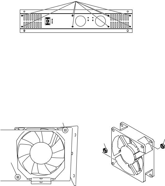
16. Fan (Time required: about 12 min.) |
16. DC 12 |
|
||
16-1 |
Remove the front panel unit. (See procedure 9.) |
16-1 |
9 |
|
16-2 |
Remove the PA unit located on the same side as the fan |
16-2 |
DC PA |
|
|
to remove. (See procedure 3.) |
|
3 |
|
16-3 |
Remove the two (2) screws marked [40] and the two (2) |
16-3 |
40 2 6 2 |
|
|
hexagonal nuts for each side. Fans can then be removed. |
|
DC Fig. 19 |
|
|
(Fig. 19) |
|
|
|
|
[40] |
|
|
|
|
|
|
|
Hexagonal Nut |
|
|
Hexagonal Nut |
6 |
|
|
|
6 |
|
|
[40]
[40]: Bind Head Screw 4.0X16 MFZN2W3 SP (WE984000) + BIND
(Fig. 19)
22
XP7000/XP5000
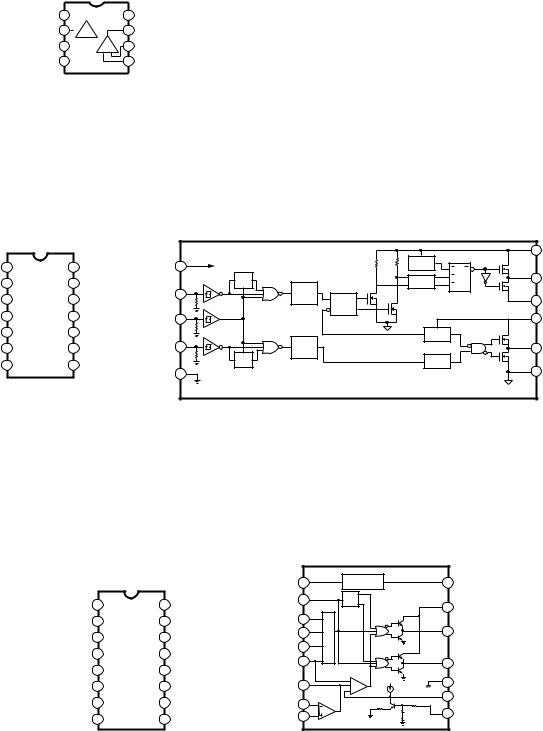
■ IC BLOCK DIAGRAMIC
•NJM2068MD-TE2 (X3505A00) Dual Operational Amplifier
XP7000 SUB: IC301, IC302, IC303, IC304, IC305 PAH: IC201
XP5000 SUB: IC301, IC302, IC303, IC304, IC305 PAH: IC201
Output A |
1 |
|
|
|
|
|
|
Inverting |
2 |
|
|
|
|
|
|
Input A |
|
- |
|
|
+ |
||
Non-Inverting |
3 |
|
|
|
|
|
|
|
|
|
|
|
|
||
Input A |
|
|
|
|
|
|
|
|
|
|
|
|
|
|
|
-DC Voltage Supply |
4 -V |
|
|
||||
|
+V 8 |
+DC Voltage |
|
|
Supply |
||
|
|
||
|
7 |
Output B |
|
+ - |
6 |
Inverting |
|
Input B |
|||
|
5Non-Inverting Input B
•IR2110 (X2382A00) Driver
XP7000 PS: IC402 XP5000 PS: IC402
LO |
1 |
14 |
|
COM |
2 |
13 |
VSS |
VCC |
3 |
12 |
LIN |
|
4 |
11 |
SD |
VS |
5 |
10 |
HIN |
VB |
6 |
9 |
VDD |
HO |
7 |
8 |
|
|
|
|
|
HV |
|
|
6 |
VB |
|
|
|
|
UV |
|
|
|
|
|
|
|
|
LEVEL |
|
|
|
|
VDD |
9 |
|
|
DETECT |
|
|
|
|
|
|
SHIFT |
R |
Q |
|
|||
|
|
|
|
|
|
|||
|
RS Q |
|
|
PULSE |
R |
7 |
HO |
|
|
VDD/VCC |
|
FILTER |
S |
|
|||
|
|
|
|
|
|
|||
HIN |
10 |
|
LEVEL |
|
|
|
|
|
|
|
|
SHIFT |
PULSE |
|
|
5 |
VS |
|
|
|
|
GEN |
|
|
|
|
SD |
11 |
|
|
|
|
|
3 |
VCC |
|
|
|
|
|
UV |
|
|
|
|
|
|
VDD/VCC |
|
DETECT |
|
|
|
LIN |
12 |
|
|
|
|
|
|
|
|
LEVEL |
|
|
|
1 |
LO |
||
|
|
S |
SHIFT |
|
|
|
|
|
|
|
|
|
DELAY |
|
|
|
|
|
R |
Q |
|
|
|
|
|
|
VSS |
13 |
|
|
|
|
|
2 |
COM |
|
|
|
|
|
|
|
||
•SG3525AN (X2383A00) Regulating Pulse Width Modulator
XP7000 PS: IC401 XP5000 PS: IC401
|
|
|
|
VREF |
16 |
|
REFERENCE |
15 |
+VIN |
|
|
|
|
|
REGULATOR |
||||
|
|
|
|
OSC. OUTPUT |
4 |
|
FLIP/ |
|
|
INV. INPUTN |
1 |
16 |
VREF |
|
FLOP |
|
|
||
|
|
|
13 |
VC |
|||||
|
|
|
|
||||||
|
|
|
|
|
|
|
|
||
N.I. INPUT |
2 |
15 |
+VIN |
SYNC |
3 |
OSCILLATOR |
|
|
|
|
|
|
|
|
|||||
SYNC |
3 |
14 |
|
RT |
6 |
A |
11 |
OUTPUT A |
|
|
|
||||||||
OUTPUT B |
|
|
|
|
|||||
|
|
|
|
|
|
||||
|
|
|
|
DISCHARGE |
7 |
|
|
|
|
OSC. OUTPUT |
4 |
13 |
VC |
CT |
5 |
|
|
|
|
|
|
|
|
|
B |
14 |
OUTPUT B |
||
CT |
|
|
|
|
|
|
|||
5 |
12 |
GROUND |
|
|
|
|
|
|
|
RT |
6 |
11 |
OUTPUT A |
COMPENSATION |
9 |
|
PWM50 A |
12 |
GROUND |
|
|
|
|||||||
|
|
|
|
|
|
|
|
8 |
SOFT-START |
DISCHARGE |
7 |
10 |
SHUTDOWN |
INV. INPUTN |
1 |
|
5K |
5K |
|
|
|
|
|
E/A |
|
|
|||
|
|
|
|
N.I. INPUT |
|
|
10 |
SHUTDOWN |
|
SOFT-START |
8 |
9 |
COMPENSATION |
2 |
|
|
|||
|
|
|
|
||||||
|
|
|
|
|
|
23

XP7000/XP5000
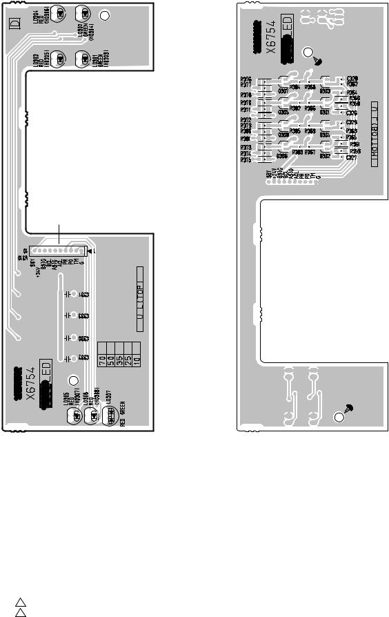
■ CIRCUIT BOARDS
CONTENTS |
|
|
|
• |
COIL Circuit Board |
(X6755B0) ............................................................. |
24 |
• |
LED Circuit Board |
(X6754D0) ............................................................ |
25 |
• |
PAH Circuit Board |
(X6750B0) ............................................................. |
26 |
• |
PS Circuit Board |
(X6752C0) ............................................................ |
28 |
• IO 1/4 Circuit Board |
(X6754D0) ............................................................ |
32 |
|
• IO 2/4 Circuit Board |
(X6754D0) ............................................................ |
33 |
|
• IO 3/4 Circuit Board |
(X6754D0) ............................................................ |
33 |
|
• IO 4/4 Circuit Board |
(X6754D0) ............................................................ |
34 |
|
• |
PSW Circuit Board |
(X6754D0) ............................................................ |
35 |
• |
VR Circuit Board |
(X6754D0) ............................................................ |
35 |
• COIL Circuit Board |
|
|
|
H/B/K/O destinations |
|
|
|
|
|
to PS-CN406 |
to PS-CN415 |
Component side |
|
|
|
L701, L702
Cord holder
Put cord holder through the holes of circuit board.
Pattern side
Component side ( )
|
Pattern side ( ) |
||
|
2NA-WF40160 |
1 |
(XP7000) |
24 |
2NA-WF40160 |
1 |
(XP5000) |
XP7000/XP5000
• LED Circuit Board
CLIP |
SIGNAL |
to PS-CN410
TEMP PROTECTION |
POWER/STANDBY |
|
Component side ( ) |
Pattern side ( ) |
|
2NA-WF39910 3 (XP7000)
2NA-WF39910 3 (XP5000) |
25 |

XP7000/XP5000
• PAH Circuit Board
to PS-CN412 (Ach) to PS-CN411 (Bch)
to IO 1/4-CN302 (Ach, Bch)
Component side ( )
to IO 3/4-W304 (Ach) |
A |
to IO 3/4-W306 (Bch) |
|
|
A' |
|
B |
Pattern side ( )
B'
2NA-WF39660 1 (XP7000)
26 |
2NA-WF39660 1 (XP5000) |

|
|
|
XP7000/XP5000 |
|
|
to PS-W401 (Ach) |
|
|
|
|
to PS-W406 (Bch) |
|
|
|
|
to PS-W402 (Ach) |
Following semi-conductors are |
||
|
to PS-W407 (Bch) |
|||
A |
to PS-W403 (Ach) |
installed for the PA unit. |
||
|
to PS-W408 (Bch) |
PA |
||
|
|
|
|
|
|
|
Ref. |
XP7000 |
XP5000 |
|
|
D124 |
O |
O |
|
|
D125 |
O |
O |
|
|
D126 |
O |
O |
|
|
D127 |
O |
O |
|
|
Q112 |
O |
O |
|
|
-115 |
O |
O |
|
|
Q116 |
O |
O |
|
|
Q117 |
O |
O |
|
|
Q135 |
O |
O |
|
|
Q136 |
O |
O |
|
|
Q218 |
O |
O |
|
|
Q118N |
O |
O |
|
|
Q118P |
O |
O |
|
|
Q119N |
O |
O |
|
|
Q119P |
O |
O |
|
|
Q120N |
O |
O |
|
|
Q120P |
O |
O |
|
|
Q121N |
O |
O |
|
|
Q121P |
O |
O |
|
|
Q122N |
O |
O |
|
|
Q122P |
O |
O |
|
|
Q123N |
O |
– |
|
|
Q123P |
O |
– |
A' |
Component side ( ) |
Q125N |
O |
O |
|
Q125P |
O |
O |
|
|
|
Q126N |
O |
O |
B |
|
Q126P |
O |
O |
|
|
PR201 |
O |
O |
|
|
PR202 |
O |
O |
|
|
O:Installed |
|
|
|
|
– :Not installed |
|
|
Pattern side ( )
B'
2NA-WF39660 1 (XP7000)
2NA-WF39660 1 (XP5000) |
27 |
XP7000/XP5000
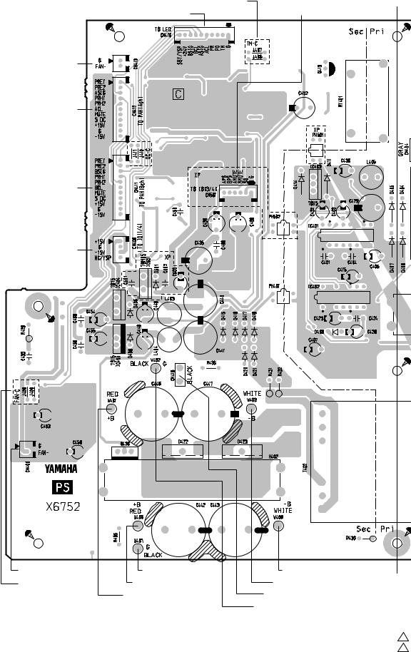
• PS Circuit Board
to FAN (Ach)
to PAH-CN201 (Ach)
to PAH-CN201 (Bch)
to IO 1/4-CN302
to FAN (Bch) FAN TEST POINT
Component side ( )
28
TEMP LED TEST POINT to LED-W310
to PAH-CN104 (Bch) to PAH-CN103 (Bch)
to PAH-CN103 (Ach)
A
to IO 3/4-CN304
to PAH-CN105 (Bch)
to PAH-CN105 (Ach) A' to IO 3/4-W305
to PAH-CN104 (Ach)
2NA-WF39710 2 (XP7000) 2NA-WF39710 2 (XP5000)
Loading...