


M395-10
CLYMER
YAMAHA
XV535-1100 VIRAGO • 1981-2003
SERVICE • REPAIR • MAINTENANCE
A PRIMEDIA Publication
CLYMER
YAMAHA
Section One:XV700-1100 Virago • 1981-1999
Section Two: XV535 Virago • 1987-2003
The world's finest publisher of mechanical how-to manuals
PRIMEDIA
Business Directories & Books
P.O. Box 12901, Overland Park, Kansas 66282-2901

Copyright ©2004 PRIMEDIA Business Magazines & Media Inc.
FIRST EDITION
First Printing February, 1986
SECOND EDITION
Revised to include 1985 and 1986 models
First Printing November, 1986
THIRD EDITION
Revised to include 1987 models
First Printing September, 1987
Second Printing April, 1988
Third Printing October, 1988
FOURTH EDITION
Revised by Ed Scott to include 1988-1990 models
First Printing First Printing February, 1991 Second Printing December, 1991
FIFTH EDITION
Revised by Ed Scott to include 1992 models
First Printing November, 1992
Printed in U.S.A.
SIXTH EDITION
Revised by Ed Scott to include 1987-1993 XV535 models and 1993 XV750 and XVI100 models
First Printing October, 1993
Second Printing Second Printing June, 1994
SEVENTH EDITION
Revised to include 1994-1995 models
First Printing April, 1995 Second Printing March, 1996
EIGHTH EDITION
First Printing June, 1997
Second Printing January, 1998
NINTH EDITION
Revised to include 1998-1999 models
First Printing June, 1999 Second Printing August, 2000 Third Printing September, 2001 Fourth Printing November, 2002
TENTH EDITION
Revised to include 2000-2003 models
First Printing May, 2004
CLYMER and colophon are registered trademarks of PRIMED1A Business Magazines & Media Inc.
ISBN: 0-89287-907-6
Library of Congress: 2004092777
MEMBER
MOTORCYCLE
INDUSTRY
COUNCIL, INC.
AUTHOR: Ed Scott.
TECHNICAL PHOTOGRAPHY: Ron Wright and Ed Scott.
TECHNICAL ILLUSTRATIONS: Steve Amos.
WIRING DIAGRAMS: Robert Caldwell.
TOOLS AND EQUIPMENT: K& L Supply at www.klsupply.com.
COVER: Mark Clifford Photography, Los Angeles, California.
All rights reserved. Reproduction or use, without express permission, of editorial or pictorial content, in any manner, is prohibited. No patent liability is assumed with respect to the use of the information contained herein. While every precaution has been taken in the preparation of this book, the publisher assumes no responsibility for errors or omissions. Neither is any liability assumed for damages resulting from use of the information contained herein. Publication of the servicing information in this manual does not imply approval of the manufacturers of the products covered.
All instructions and diagrams have been checked for accuracy and ease of application; however, success and safety in working with tools depend to a great extent upon individual accuracy, skill and caution. For this reason, the publishers are not able to guarantee the result of any procedure contained herein. Nor can they assume responsibility for any damage to property or injury to persons occasioned from the procedures. Persons engaging in the procedure do so entirely at their own risk.
Chapter One
General Information
Chapter Two
Troubleshooting
Chapter Three
Lubrication, Maintenance and Tune-up
Chapter Four
Engine
Chapter Five
Clutch and Transmission
Chapter Six
Fuel and Exhaust Systems
Chapter Seven
Electrical System
Chapter Eight
Front Suspension and Steering
Chapter Nine
Rear Suspension
Chapter Ten
Brakes
Chapter Eleven
Suspension Adjustment
Index
Wiring Diagrams

CLYMER.
Publisher Shawn Etheridge
EDITORIAL
Managing Editor
James Grooms
Associate Editor
Jason Beaver
Lee Buell
Technical Writers
Jay Bogart
Michael Morlan
George Parise
Mark Rolling
Ed Scott
Ron Wright
Editorial Production Manager
Dylan Goodwin
Senior Production Editor
Greg Araujo
Production Editors
Holly Messinger
Shara Pierceall
Darin Watson
Associate Production Editor
Susan Hartington
Julie Jantzer
Justin Marciniak
Technical Illustrators
Steve Amos
Errol McCarthy
Mitzi McCarthy
Bob Meyer
Mike Rose
MARKETING/SALES AND ADMINISTRATION
Advertising & Promotions Manager
Elda Starke
Advertising & Promotions Coordinators |
' |
|
Melissa Abbott |
|
|
Wendy Stringfellow |
|
|
Art Director |
|
|
Chris Paxton |
|
|
Sales Managers |
|
|
Ted Metzger, Manuals |
|
|
Dutch Sadler, Marine |
|
|
Matt Tusken, Motorcycles |
|
|
Business Manager |
|
|
Ron Rogers |
|
|
Customer Service Manager |
|
|
Terri Cannon |
|
|
Customer Service Supervisor |
|
|
Ed McCarty |
|
|
Customer Service Representatives |
|
|
Shawna Davis |
|
|
Courtney Hollars |
'",-• |
|
Susan Kohlmeyer |
|
|
April LeBlond |
|
|
Jennifer Lassiter |
|
|
Ernesto Suarez |
|
|
Warehouse & Inventory Manager
Leah Hicks
PRIMEDIA
Business Magazines & Media
P.O. Box 12901, Overland Park, KS 66282-2901 • 800-262-1954 • 913-967-1719
The following books and guides are published by PRIMEDIA Business Directories & Books.
CLYMER.
More information available at primediabooks.com
CLYMER
YAMAHA
Section One:XV700-1100 Virago • 1981-1999
The XV535 Virago 1987-2003 models are covered in Section Two of this book.

CONTENTS— Section One
XV700-1100 Virago • 1981-1999
QUICK REFERENCE DATA
CHAPTER ONE
GENERAL INFORMATION
Manual organization
Service hints
Torque specifications
Safety first
Special tips
Expendable supplies
CHAPTER TWO
TROUBLESHOOTING
Operating requirements
Troubleshooting instruments
Emergency troubleshooting
Engine starting
Engine performance
Engine noises
Excessive vibration
CHAPTER THREE
LUBRICATION, MAINTENANCE AND TUNE-UP
Routine checks
Maintenance intervals
Tires and wheels
Battery
IX
1
Parts replacement Serial numbers Basic hand tools
Tune-up and troubleshooting tools Mechanic's tips
16
Clutch
Transmission
Front suspension and steering
Brake problems
Electrical problems
Ignition system
20
Lubrication
Maintenance
Drive chain
Tune-up

CHAPTER FOUR |
|
ENGINE |
56 |
Engine principles |
Oil level switch |
Servicing in frame |
Neutral switch |
Engine removal/installation |
Timing gears |
Cylinder heads and camshafts |
Primary drive gear |
Valves and valve components |
Crankcase |
Rocker arm assemblies |
Crankshaft and connecting rods |
Cylinder |
Middle drive gear |
Pistons and piston rings |
Starter gears |
Oil pump/strainer |
Break-in |
Oil pressure relief valve |
|
CHAPTER |
FIVE |
|
CLUTCH |
AND TRANSMISSION |
100 |
Clutch |
|
Shift mechanism |
Clutch cable |
Transmission |
|
Drive sprocket |
Shift drum and forks |
|
CHAPTER |
SIX |
|
FUEL AND |
EXHAUST SYSTEMS |
116 |
Air cleaner |
|
Fuel shutoff valve |
Carburetors |
Fuel filter |
|
Coasting enrichener system |
Fuel pump |
|
Fuel level measurement |
Fuel tank |
|
Choke cable adjustment |
Crankcase breather system |
|
Rejetting carburetors |
Mixture control valve |
|
Throttle cable replacement |
Air induction system |
|
Choke cable replacement |
Exhaust system |
|
CHAPTER SEVEN |
|
ELECTRICAL SYSTEM |
145 |
Charging system |
Starting system |
Alternator |
Electrical components |
Voltage regulator/rectifier |
Lighting system |
Ignition system |
Switches |
Ignitor unit |
Computerized monitor system |
Ignition coil |
Fuel pump testing |
Pickup coil |
Fuel warning light system |
Spark plugs |
Horn |
Pressure sensor |
Fuses |

CHAPTER EIGHT |
|
FRONT SUSPENSION AND STEERING |
190 |
Front wheel |
Tire repairs |
Front hub |
Handlebar |
Wheel balance |
Handlebar adjustment |
Wire wheel service |
Steering head |
Tire changing |
Front fork |
CHAPTER NINE |
|
REAR SUSPENSION AND FINAL DRIVE |
216 |
Rear wheel |
Tire changing |
Rear hub |
Final shaft drive unit |
Clutch hub |
Swing arm |
Drive chain assembly |
Shock absorbers |
Wheel balancing |
|
CHAPTER TEN |
|
BRAKES |
233 |
Front disc brake |
Front brake disc |
Master cylinder |
Rear drum brake |
Front brake pad replacement |
Rear brake pedal assembly |
Front caliper |
Bleeding the system |
Front brake hose replacement |
|
CHAPTER ELEVEN |
|
SUSPENSION ADJUSTMENT |
250 |
Front fork |
Rear shock absorbers |
INDEX |
255 |
WIRING DIAGRAMS |
257 |
QUICK REFERENCE DATA |
|
|
|
XV700-1100 |
|
|
FUSES |
|
|
Amperage |
|
|
|
|
Main |
|
|
XV920J,XV1100 |
30 |
|
All others |
20 |
|
Headlight |
15 |
|
Signal |
15 |
|
Ignition |
10 |
|
Tail |
10 |
|
Reserve |
|
|
XV700,XV1000,XV1100 |
20 |
|
XV920J |
30 |
|
All other models |
Not specified. |
|
|
|
|
|
APPROXIMATE REFILL CAPACITIES |
|
Engine oil |
|
|
With filter change |
3.3 quarts (3,100 cc) |
|
Without filter change |
3.2 quarts (3,000 cc) |
|
Engine rebuild |
3.8 quarts (3,600 cc) |
*' |
Front fork |
|
|
XV700 (1984-1985) |
13.2 oz. (389 cc) |
|
XV700 (1986-1987) |
13.4 oz. (396 cc) |
|
XV750 (1981-1983) |
9.4 oz. (278 cc) |
|
XV750 (1988-1994) |
13.4 oz. (396 cc) |
|
XV920 (1981-1982 chain drive) |
8.9 oz. (264 cc) |
|
XV920 (1982-1983 shaft drive) |
10.2 oz. (303 cc) |
|
XV1000,XV1100 |
12.6 oz. (372 cc) |
|
Final gear case (if so equipped) |
0.21 qt. (200 cc) |
|
|
|
|
|
RECOMMENDED LUBRICANTS |
|
Engine oil |
|
|
40° F and above |
SAE 20W/40, SE-SF |
|
40° F and below |
SAE10W/30,SE-SF |
|
Brake fluid |
DOT 3 or DOT 4 |
|
Battery refilling |
Distilled water |
|
Fork oil |
SAE 10 |
|
Cables and pivot points |
Yamaha chain and cable lube or |
|
Fuel |
SAE 10W/30 motor oil |
, |
Regular |
/ |
|
Final gear oil (if so equipped) |
|
/ |
All weather |
SAE 80W/90, GL4 |
/ |
Above 40° F |
SA 90, GL4 |
/ |
Below 40° F |
SAE 80, GL4 |
|
Drive chain (if so equipped) |
Shell Aivania 1 or |
|
|
lithium-base EP2 grease |
|
|
|
|
XI
TIRE INFLATION PRESSURE (COLD)
|
XV700, XV750, |
|
|
XV1000.XV1100 |
XV920 |
Load |
psi (kg/cm2) |
psi (kg/cm2) |
Up to 1981b. (90 kg) |
|
|
Front |
26(1.8) |
26(1.8) |
Rear |
28 (2.0) |
28 (2.0) |
198-353 Ib. (90-160 kg) |
|
|
Front |
28 (2.0) |
|
Rear |
32 (2.3) |
|
353-529 !b. (160-240 kg) |
|
|
Front |
28 (2.0) |
|
Rear |
40 (2.8) |
|
198-470 Ib. (90-213 kg) |
— |
|
Front |
28 (2.0) |
|
Rear |
— |
32 (2.3) |
High-speed riding |
|
|
Front |
32 (2.3) |
28 (2.0) |
Rear |
36 (2.5) |
32 (2.3) |
|
|
|
|
REPLACEMENT BULBS |
Item |
Wattage |
|
|
Headlight |
12V60/55W |
Tail/brakelight |
12V8/27W |
Meter light |
|
XV920J |
12V 2W |
All other models |
12V3.4W |
Indicator lights |
|
1981-1983 |
12V3.4W |
1984-on |
12V4.0W |
License light |
|
XV750 |
12V 8W |
XV920J |
12V3.8W |
All other models |
Not specified |
Flasher/running light |
|
XV700,XV1000,XV1100 |
12V27W |
XV920J |
12V27WX4/8W |
All other models |
Not specified |
|
|
TUNE-UP SPECIFICATIONS |
|
Ignition timing |
Fixed |
Valve clearance (cold) |
|
1981-1983 |
|
Intake |
0.004 in. (0.10 mm) |
Exhaust |
0.006 in. (0.15 mm) |
1984-on |
|
Intake |
0.003-0.005 in. (0.07-0.10 mm) |
Exhaust |
0.006 in. (0.15 mm) |
Spark plug |
|
Type |
NGK BP7ES |
Gap |
0.028-0.032 in. (0.7-0.8 mm) |
Tightening torque |
14.5ft.-lb. (20N«m) |
Idle speed |
950-1,050 rpm |
Compression pressure (warm @ sea level) |
|
Standard |
156 psi (11 kg/cm2) |
Minimum |
128 psi (9 kg/cm2) |
Maximum |
171 psi (12 kg/cm2) |
Maximum difference between cylinders: |
14 psi (1.0 kg/cm2) |
XII
INTRODUCTION
This portion of this detailed and comprehensive manual covers all 1981-1999 Yamaha XV700-XV1100 V-Twins. Two versions of the Model 920 have been produced, chain-driven and shaft-driven. The Euro-style, chain-drive models were offered in 1981 and 1982 and are identified by an R preceeding the model number. In addition, Yamaha also offered a shaft-driven Model 920 during 1982. For 1983, however, all 920 models, including all other models covered in this manual, are shaft-driven.
The expert text contained within this manual gives complete information on maintenance, tune-up, repair and overhaul. Hundreds of photos and drawings guide you through every step. The book includes all you need to know to keep your Yamaha running right.
Where repairs are practical for the owner/mechanic, complete procedures are given. Equally important, difficultjobs are pointed out. Such operations are usually more economically performed by a dealer or independent garage.
A shop manual is a reference. You want to be able to find information fast. As in all Clymer books, this one is designed with this in mind. All chapters are thumb tabbed. Important items are extensively indexed at the rear of the book. All the most frequently used specifications and capacities are summarized on the Quick Reference pages at the front of the book.
Keep the book handy in your tool box and take it with you on long trips. It will help you to better understand your Yamaha, lower repair and maintenance costs and generally improve your satisfaction with your bike.
CHAPTER ONE
GENERAL INFORMATION
This detailed, comprehensive manual covers Yamaha XV700-1100 models. The expert text gives complete information on maintenance, tune-up, repair and overhaul. The book includes all you need to know to keep your Yamaha running right.
A shop manual is a reference. You want to be able to find information fast. As in all Clymer books, this one is designed with you in mind. All chapters are thumb-tabbed. Important items are extensively indexed at the rear ofthe book. All procedures, tables, photos, etc., in this manual assume that the reader may be working on the bike or using this manual for the first time. All the most frequently used specifications and capacities are summarized in the Quick Reference Data pages at die front of the book.
Keep the book handy in your tool box. It will help you to better understand how your Yamaha runs, lower repair and maintenance costs and generally improve your satisfaction witli the bike.
Table 1 lists engine serial numbers for 1981-1996 models. Table 2 lists the primary identification numbers for 1997-1999 models. Table 3 lists general specifications. Tables 1-4 are at the end of this chapter.
MANUAL ORGANIZATION
All dimensions and capacities are expressed in English units familiar to U.S. mechanics as well as in metric units.
This chapter provides general information and discusses equipment and tools useful both for preventative maintenance and troubleshooting.
Chapter Two provides methods and suggestions for quick and accurate diagnosis and repair of problems. Troubleshooting procedures discuss typical symptoms and logical methods to pinpoint the trouble.
Chapter Three explains all periodic lubrication and routine maintenance necessary to keep your Yamaha running well. Chapter Three also includes recommended tune-up procedures, eliminating the need to constantly consult chapters on the various assemblies.
Subsequent chapters describe specific systems such as the engine, clutch, transmission, fuel, exhaust, suspension, steering and brakes. Each chapter provides disassembly, repair and assembly procedures in simple step-by-step form. If a repair is impractical for a home mechanic, it is so indicated. It is usually faster and less expensive to take such repairs to a dealer or competent repair shop. Specifications concerning a particular system are included at the end of the appropriate chapter.
Some of the procedures in this manual specify special tools. In most cases, the tool is illustrated either in actual use or alone. Well equipped mechanics may find tiiey can substitute similar tools already on hand or fabricate their own.

2
The terms NOTE, CAUTION and WARNING have specific meanings in this manual. A NOTE provides additional information to make a step or procedure easier or clearer. Disregarding a NOTE could cause inconvenience, but would not cause equipment damage or personal injury.
A CAUTION emphasizes areas where equipment damage could result. Disregarding a CAUTION could cause permanent mechanical damage; however, personal injury is unlikely.
A WARNING emphasizes areas where personal injury or even death could result from negligence. Mechanical damage may also occur. WARNINGS are to be taken seriously. In some cases, serious injury and death have resulted from disregarding similar warnings.
Throughout this manual keep in mind 2 conventions. "Front" refers to the front of the Yamaha. The front of any component, such as the engine, is the end which faces toward the front of the vehicle. The "left-" and "right-hand" sides refer to the position of the parts as viewed by a rider sitting on the seat facing forward. For example, the throttle control is on the right-hand side and the clutch lever is on the left-hand side. These rules are simple, but even experienced mechanics occasionally become disoriented.
SERVICE HINTS
Most of the service procedures covered are straightforward and can be performed by anyone reasonably handy with tools. It is suggested, however, that you consider your own capabilities carefully before attempting any operation involving major disassembly of the engine.
Some operations, for example, require the use of a press. It would be wiser to have these operations performed by a shop equipped for such work, rather than to try to do the job yourself with makeshift equipment. Other procedures require precise measurements. Unless you have the skills and equipment required, it would be better to have a qualified repair shop make the measurements for you.
There are many items available that can be used on your hands before and after working on your bike. A little preparation prior to getting "all greased up" will help during clean-up.
Before starting out, work Vaseline, soap or a product such as Pro-Tek (Figure 1) onto your forearms, into your hands and under your fingernails and cuticles. This will make clean-up a lot easier.
For clean-up, use a waterless hand soap such as Sta-Lube and then finish up with powered Boraxo and a fingernail brush.
CHAPTER ONE
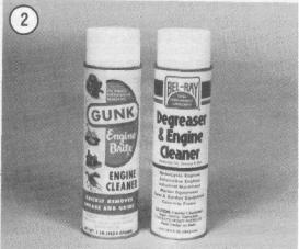
Repairs go much faster and easier if your machine is clean before you begin work. There are many special cleaners, such as Gunk or Bel-Ray Degreaser (Figure 2), for washing the engine and related parts. Just follow the manufacturer's directions on the container for the best results. Then rinse it away with a heavy spray of water from a garden hose. Clean all oily or greasy parts with cleaning solvent as you remove them.
WARNING
Never use gasoline as a cleaning agent. It presents an extreme fire hazard. Be sure to work in a well-ventilated area when using cleaningsolvent. Keep afire extinguisher, rated for gasoline fires, handy in any case.
Special tools are required for some repair procedures. These may be purchased at a dealer, rented from a tool rental shop or fabricated by a mechanic or machinist (often at considerable savings).
Much of the labor charges for repairs made by dealers are for the labor hours involved during the removal, disassembly, assembly and installation of other parts in order to reach the defective part. It is frequently possible to perform the preliminary operations yourself and then take the defective unit to the dealer for repair.
Once you have decided to tackle the job yourself, read the entire section in this manual which pertains to the job, making sure you have identified the proper section. Study the illustrations and text until you have a good idea of what is involved in completing the job satisfactorily. If special tools or replacement parts are required, make arrangements to get them before you start. It is frustrating and time-consuming to get partly into a job and then be unable to complete it.
Simple wiring checks can be easily made at home, but knowledge of electronics is almost a
GENERAL INFORMATION |
3 |
necessity for performing tests with complicated electronic testing gear.
During disassembly keep a few general cautions in mind. Force is rarely needed to get things apart. If parts are a tight fit, such as a bearing in a case, there is usually a tool designed to separate them. Never use a screwdriver to pry apart parts with machined surfaces such as crankcase halves. You will mar the surfaces and end up with leaks.
Make diagrams (or take an instant picture) wherever similar-appearing parts are found. For instance, crankcase bolts are often not the same length. You may think you can remember where everything came from, but mistakes are costly. There is also the possibility that you may be sidetracked and not return to work for days or even weeks and the carefully laid out parts may get moved.
Tag all similar internal parts for location and mark all mating parts for position. Record number and thickness of any shims as they are removed. Small parts such as bolts can be identified by placing them in plastic sandwich bags. Seal and label them with masking tape.
Wiring should be tagged with masking tape marked as each wire is removed. Again, do not rely on memory alone.
Protect finished surfaces from physical damage or corrosion. Keep gasoline and hydraulic (brake) fluid off painted surfaces.
Frozen or very tight bolts and screws can often be loosened by soaking with a penetrating oil, such as WD-40 or Liquid Wrench, then striking the bolt head sharply with a hand impact driver. Avoid heat unless absolutely necessary, since it may melt, warp or remove the temper from many parts.
No parts, except those assembled with a press fit, require unusual force during assembly. If a part is
hard to remove or install, find out why before proceeding.
Cover all openings after removing parts to keep dirt, small tools, etc., from falling in.
When assembling 2 parts, start all fasteners, then tighten evenly.
Wiring connections and brake shoes should be kept clean and free of grease and oil.
When assembling parts, be sure all shims and washers are installed exactly as they came out.
Whenever a rotating part butts against a stationary part, look for a shim or washer. Use new gaskets if there is any doubt about the condition of the old ones. A thin coat of oil on non-pressure type gaskets may help them seal more effectively.
Heavy grease can be used to hold small parts in place if they tend to fall out during assembly. However, keep grease and oil away from electrical and brake components.
High spots may be sanded off a piston with sandpaper, but fine emery cloth and oil will do a much more professional job.
Carbon can be removed from the head, the piston crowns and the exhaust ports with a dull screwdriver. Do not scratch the surface. Wipe off the surface with a clean cloth when finished.
The carburetors are best cleaned by disassembling them and soaking the parts in a commercial carburetor cleaner. Never soak gaskets and rubber parts in these cleaners. Never use wire to clean out jets and air passages; they are easily damaged. Use compressed air to blow out the carburetor after the float has been removed.
A baby bottle makes a good measuring device for adding oil to the front forks and final drive. Get one that is graduated in fluid ounces and cubic centimeters. After it has been used for this purpose, do not let a small child drink out of it as there will always be an oil residue in it.
Take your time and do the job right. Do not forget that a newly rebuilt engine must be broken in in the same manner as a new one. Keep the rpm within the limits given in your owner's manual when you get back on the road.
TORQUE SPECIFICATIONS
Torque specifications throughout this manual are given in foot-pounds (ft.-lb.) and Newton Meters (N«m). Newton meters are being adopted in place of meter kilograms (mkg) in accordance with the International Modernized Metric System. Tool manufacturers now offer torque wrenches calibrated in Newton meters.
Existing torque wrenches calibrated in meter kilograms can be used by performing a simple
4 |
|
CHAPTER ONE |
conversion. All you have to do is move the decimal point one place to the right; for example, 4.7 mkg = 47 N«m. This conversion is sufficient for use in this manual even though the exact mathematical conversion is 3.5 mkg = 34.3 N.m.
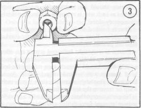
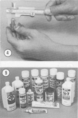
General torque specifications are listed in the individual chapters. For those components that are not listed, refer to Table 2 for a general listing of nut and bolt tightening torques. To use the table, first determine the size of the nut or bolt. Figure 3 and Figure 4 show how this is done.
SAFETY FIRST
Professional mechanics can work for years and never sustain a serious injury. If you observe a few rules of common sense and safety, you can enjoy many safe hours servicing your own machine. If you ignore these rules you can hurt yourself or damage the bike.
1.Never use gasoline as a cleaning solvent.
2.Never smoke or use a torch in the vicinity of flammable liquids, such as cleaning solvent, in open containers.
3.If welding or brazing is required on the machine, remove the fuel tank(s) (and any gas-filled shock absorber) to a safe distance, at least 50 feet away.
4.Use the proper sized wrenches to avoid damage to nuts and injury to yourself.
5.When loosening a tight or stuck nut, think about what would happen if the wrench should slip. Be careful; protect yourself accordingly.
6.Keep your work area clean and uncluttered.
7.Wear safety goggles during all operations involving drilling, grinding or using a cold chisel.
8.Wear safety goggles when using chemicals, such as solvent, and when using compressed air to clean and dry parts.
9.Never use worn-out tools.
10.Keep a fire extinguisher handy; be sure it is rated for gasoline and electrical fires.
SPECIAL TIPS
Because ofthe extreme demands placed on a bike, several points should be kept in mind when performing service and repair. The following items are general suggestions that may improve the overall life of the machine and help avoid costly failures.
1. Use a locking compound, such as Loctite 242, on all bolts and nuts, even if they are secured with lockwashers. This type of Loctite does not harden completely and allows easy removal of the bolt or
nut. A screw or bolt lost from an engine cover or bearing retainer could easily cause serious and expensive damage before its loss is noticed.
When applying Loctite, use a small amount. If too much is used, it can work its way down the threads and stick parts together not meant to be stuck.
2.Use a hammer-driven impact driver to remove tight screws, particularly engine cover screws. These tools help prevent the rounding off of screw heads and ensure a tight installation.
3.When straightening out the "fold-over" type lockwasher (usually used on the clutch nut), use a wide-blade chisel such as an old, dull wood chisel. Such a tool provides better contact on the folded tab, making straightening out easier.
4.When installing the "fold-over" type lockwasher, always use a new washer if possible. If a new washer is not available, always fold over a part ofthe washer that has not been previously folded.
Reusing the same fold may cause the washer to break, resulting in the loss of its locking ability and a loose piece of metal adrift in the engine.
When folding the washer over, start the fold with a screwdriver and finish it with a pair of pliers. If a punch is used to make the fold, the fold may be too sharp, thereby increasing the chances of the washer breaking under stress.
These washers are relatively inexpensive and it is suggested that you keep several of each size in your tool box for field repairs.
5. When replacing missing or broken fasteners (nuts, bolts and screws), especially on the engine or frame components, always use Yamaha replacement parts. They are specially hardened for each application. The wrong 50-cent bolt could easily cause serious damage and rider injury.
GENERAL INFORMATION |
5 |
6. When installing gaskets in the engine, always use Yamaha replacement gaskets without sealer, unless designated. These gaskets are designed to swell when they come in contact with oil. Gasket sealer will prevent the gaskets from swelling as intended, which can result in oil leaks. These Yamaha gaskets are cut from material of the precise thickness needed. Installation of a too thick or too thin gasket in a critical area could cause engine damage.
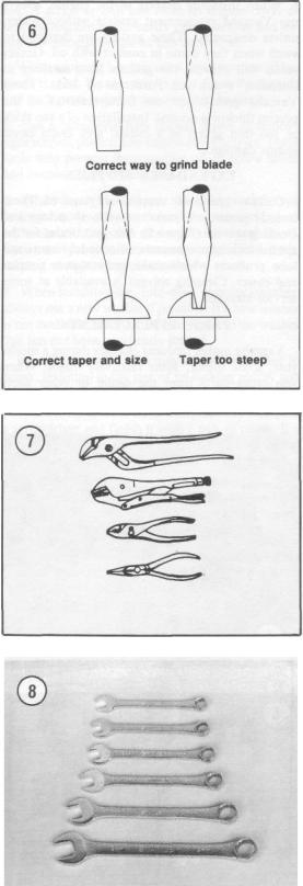
EXPENDABLE SUPPLIES
Certain expendable supplies are required. These include grease, oil, gasket cement, shop rags and cleaning solvent (Figure 5). Ask your dealer for the special locking compounds, silicone lubricants and lube products which make maintenance simpler and easier. Cleaning solvent is available at some service stations.
PARTS REPLACEMENT
Yamaha makes frequent changes during a model year, some minor, some relatively major. When you order parts from the dealer or other parts distributor, always order by engine and frame
number. Write the numbers down and carry them with you. Compare new parts to old before purchasing them. If they are not alike, have the parts manager explain the difference to you.
SERIAL NUMBERS
You must know the model serial number for registration purposes and when ordering replacement parts.
The frame serial number and the vehicle identification number (VIN) are stamped on the right-hand side of the steering head. The engine number is located on the lower right-hand side of the crankcase.
BASIC HAND TOOLS
A number of tools are required to maintain your Yamaha in top riding condition. You may already have some around for other work like home or car repairs. There are also tools made especially for bike repairs; these you will have to purchase. In any case, a wide variety of quality tools will make bike repairs more effective and easier.
Top quality tools are essential; they are also more economical in the long run. If you are now starting to build your tool collection, stay away from the "advertised specials" featured at some parts houses, discount stores and chain drug stores. These are usually a poor grade tool that can be sold cheaply and that is exactly what they are—cheap. They are usually made of inferior material and are thick, heavy and clumsy. Their rough finish makes them difficult to clean and they usually don't last very long. Also be careful when lending tools to "friends"—make sure they return tools promptly; if not, your collection will soon disappear.
Quality tools are made of alloy steel and are heat treated for greater strength. They are lighter and better balanced than cheap ones. Their surface is smooth, making them a pleasure to work with and easy to clean. The initial cost of good quality tools may be more but it is cheaper in the long run. Don't try to buy everything in all sizes in the beginning; do it a little at a time until you have the necessary tools.
Keep your tools clean and in a tool box. Keep them organized with the sockets and related drives together, the open-end and box wrenches together, etc. After using a tool, wipe off dirt and grease with a clean cloth and put the tool in its correct place. Doing this will save a lot of time you would have spent trying to find a socket buried in a bunch of clutch parts.
The following tools are required to perform virtually any repair job on a bike. Each tool is
6
described and the recommended size given for starting a tool collection. Table 4 includes all the tools that should be on hand for simple home repairs or major overhauls. Additional tools and some duplications may be added as you become more familiar with the bike. Almost all motorcycles and bikes (with the exception of the U.S.-built Harley and some English bikes) use metric-size bolts and nuts. If you are starting your collection now, buy metric sizes.
Screwdrivers
The screwdriver is a very basic tool, but if used improperly it will do more damage than good. The slot on a screw has a definite dimension and shape. A screwdriver must be selected to conform with that shape. Use a small screwdriver for small screws and a large one for large screws or the screw head will be damaged.
Two basic types of screwdriver are required to repair the bike—a common (flat blade) screwdriver and the Phillips screwdriver.
Screwdrivers are available in sets which often include an assortment of common and Phillips blades. If you buy them individually, buy at least the following:
a.Common screwdriver—5/16X6 in. blade.
b.Common screwdriver—3/8X12 in. blade.
c.Phillips screwdriver—size 2 tip, 6 in. blade. Use screwdrivers only for driving screws. Never
use a screwdriver for prying or chiseling. Do not try to remove a Phillips or Allen head screw with a common screwdriver; you can damage the head so that the proper tool will be unable to remove it. Keep screwdrivers in the proper condition and they will last longer and perform better. Always keep the tip of a common screwdriver in good condition. Figure 6 shows how to grind the tip to the proper shape if it becomes damaged. Note the parallel sides of the tip.
Pliers
Pliers come in a wide range of types and sizes. Pliers are useful for cutting, bending and crimping. They should never be used to cut hardened objects or to turn bolts or nuts. Figure 7 shows several pliers useful in bike repairs.
Each type of pliers has a specialized function. Gas pliers are general purpose pliers used mainly for holding things and for bending. Locking pliers are used as pliers or to hold objects very tight like in a vise. Needlenose pliers are used to hold or bend small objects. Channel lock pliers can be adjusted to hold various sizes of objects; the jaws remain parallel to grip around objects such as pipe
CHAPTER ONE
GENERAL INFORMATION |
7 |
or tubing. There are many more types of pliers. The ones described here are the most commomly needed for bike repairs.
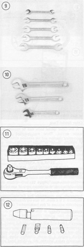
Box and Open-end Wrenches
Box and open-end wrenches are available in sets or separately in a variety of sizes. See Figure 8 and Figure 9. The size number stamped near the end refers to the distance between 2 parallel flats on the hex head bolt or nut.
Box wrenches are usually superior to open-end wrenches. An open-end wrench grips the nut on only 2 flats. Unless it fits well, it may slip and round off the points on the nut. The box wrench grips on all 6 flats. Both 6-point and 12-point openings are available on box wrenches. The 6-point gives superior holding power; the 12-point allows a shorter swing.
Combination wrenches which are open on one side and boxed on the other are also available. Both ends are the same size.
Adjustable (Crescent) Wrench
An adjustable wrench (also called Crescent wrench) can be adjusted to fit nearly any nut or bolt head. See Figure 10. However, it can loosen and slip, causing damage to the nut and maybe to your knuckles. Use an adjustable wrench only when other wrenches are not available.
Crescent wrenches come in sizes ranging from 4-18 in. overall. A 6 or 8 in. wrench is recommended as an all-purpose wrench.
Socket Wrenches
This type is undoubtedly the fastest, safest and most convenient to use. See Figure 11. Sockets which attach to a ratchet handle are available with 6-point or 12-pomt openings and 1/4, 3/8 and 3/4 inch drives. The drive size indicates the size of the square hole which mates with the ratchet handle. The 3/8 inch drive is most commonly used for bike repair.
Torque Wrench
A torque wrench is used with a socket to measure how tight a nut or bolt is installed. They come in a wide price range and with either 3/8 or 1/2 in. square drive. The drive size indicates the size of the square drive which mates with the socket. Purchase one that measures 0-100 ft.-lb. (0-140 NTn).
Impact Driver
This tool might have been designed with the motorcyclist in mind. See Figure 12. It makes

8 |
CHAPTER ONE |
removal of engine and clutch parts easy and eliminates damage to bolts and screw slots. This tool is available at most large hardware, motorcycle or auto parts stores.
Circlip Pliers
Circlip pliers (sometimes referred to as snap ring pliers) are necessary to remove the circlips used on the transmission shaft assemblies. See Figure 13.
Hammers
The correct hammer is necessary for bike repairs. Use only a hammer with a face (or head) of rubber or plastic or the soft-faced type that is filled with buckshot. These are sometimes necessary in engine teardowns. Never use a metal-faced hammer on the bike as severe damage will result in most cases. You can always produce the same amount of force with a soft-faced hammer.
Ignition Gauge
This tool has both flat and wire measuring gauges and is used to measure spark plug gap. See Figure 14. This device is available at most auto or motorcycle supply stores.
Vernier Caliper
This tool is invaluable when reading inside, outside, depth and step measurements to close precision in either metric or inch scales. Some calipers are manufactured with both scales. The
vernier caliper can be purchased from large dealers or mail order houses. See Figure 15.
Other Special Tools
A few other special tools may be required for major service. These are described in the appropriate chapters and are available either from a Yamaha dealer or other manufacturers as indicated.
TUNE-UP AND
TROUBLESHOOTING TOOLS
Multimeter or VOM
This instrument (Figure 16) is invaluable for electrical system troubleshooting and service. A few of its functions may be duplicated by homemade test equipment, but for the serious mechanic it is a must. Its uses are described in the applicable sections of this book.
Compression Gauge
An engine with low compression cannot be properly tuned and will not develop full power. A compression gauge measures engine compression. The one shown in Figure 17 has a flexible stem which enables it to reach cylinders where little clearance exists between the cylinder head and frame.
GENERAL INFORMATION |
9 |
Strobe Timing Light
This instrument is necessary for tuning. By flashing a light at the precise instant the spark plug fires, the position of the timing mark can be seen. Under the flashing light marks on the alternator flywheel line up with the stationary mark on the crankcase while the engine is running.
Suitable lights range from inexpensive neon bulb types to powerful xenon strobe lights. See Figure 18. Neon timing lights are difficult to see and must be used in dimly lit areas. Xenon strobe timing lights can be used outside in bright sunlight. Both types work on the Yamaha; use according to the manufacturer's instructions.
Portable Tachometer
A portable tachometer is necessary for tuning. See Figure 19. Ignition timing and carburetor adjustments must be performed at the specified engine speed. The best instrument for this purpose is one with a low range of 0-1,000 or 0-2,000 rpm and a high range of 0-4,000 rpm. Extended range (0-6,000 or 0-8,000 rpm) instruments lack accuracy at lower speeds. The instrument should be capable of detecting changes of 25 rpm on the low range.
MECHANIC'S TIPS
Removing Frozen Nuts and Screws
When a fastener rusts and cannot be removed, several methods may be used to loosen it. First, apply penetrating oil such as Liquid Wrench or WD-40 (available at hardware or auto supply stores). Apply it liberally and let it penetrate for 10-15 minutes. Rap the fastener several times with a small hammer; do not hit it hard enough to cause damage.
For frozen screws, apply penetrating oil as described, then insert a screwdriver in the slot and rap the top of the screwdriver with a hammer. This loosens the rust so the screw can be removed in the normal way. If the screw head is too chewed up to use this method, grip the head with locking pliers and twist the screw out.
Remedying Stripped Threads
Occasionally, threads are stripped through carelessness or impact damage. Often the threads can be cleaned up by running a tap (for internal threads on nuts) or die (for external threads on bolts) through the threads. See Figure 20. To clean or repair spark plug threads, a spark plug tap can be used (Figure 21).
Removing Broken Screws or Bolts
When the head breaks off a screw or bolt, several methods are available for removing the remaining portion.

10 |
CHAPTER ONE |
If a large portion of the remainder projects out, try gripping it with locking pliers. If the projecting portion is too small, file it to fit a wrench or cut a slot in it to fit a screwdriver. See Figure 22.
If the head breaks off flush, use a screw extractor. To do this, centerpunch the exact center of the remaining porton of the screw or bolt. Drill a small hole in the screw and tap the extractor into the hole. Back the screw out with a wrench on the extractor. See Figure 23.
GENERAL INFORMATION |
11 |
Table 1 ENGINE SERIAL NUMBERS (1981-1996) |
|
Model number |
Engine serial No. |
and year |
start to end |
|
|
1981 |
4X7-000101 to 4X7-200100 |
XV750H |
|
XV920RH |
5H1-000101 to 5H1-100100 |
1982 |
4X7-200101 to 4X7-300100 |
XV750J |
|
XV920J |
10L-000101 to * |
XV920RJ |
5H1-100101 to * |
1983 |
4X7-300101 to * |
XV750K |
|
XV750MK |
20X-000101 to * |
XV920K |
24M-000101 to * |
XV920MK |
27Y-000101 to * |
1984 |
|
XV700L |
42W-000101 to * |
XV700LC |
42X-000101 to * |
XV1000L |
42G-000101 to * |
XV1000LC |
42H-000101 to * |
1985 |
56E-000101 to * |
XV700N |
|
XV700NC |
56F-000101 to * |
XV1000N |
56V-000101 to * |
XV1000NC |
56W-000101 to * |
1986 |
1RR-000101 to 1RR-010100 |
XV700SS |
|
XV700SSC |
1TU-000101 to 1TU-005100 |
XV700CS |
1RM-000101 to 1RM-014100 |
XV700CSC |
1RV-000101 to 1RV-015100 |
XV1100S |
1TE-000101 to 1TE-015100 |
XV1100SC |
1TA-000101 to 1TA-005100 |
1987 |
|
XV700ST |
1RR-010101 to * |
XV700STC |
1TU-005101 to * |
XV700CT |
1RM-014101 to * |
XV700CTC |
1RV-005101 to * |
XV1100T |
1TE-015101 to * |
XV1100TC |
1TA-005101 to * |
1988 |
|
XV750U |
3AL-000101 to * |
XV750UC |
3CM-000101 to * |
XV1100U |
1TE-029101 to * |
XV1100UC |
1TA-007101 to * |
1989 |
3AL-007101 to * |
XV750W |
|
XV750WC |
3CM-002101 to * |
XV1100W |
1TE-035101 to * |
XV1100WC |
1TA-009101 to * |
1990 |
|
XV750A |
3AL-01301 to * |
XV750AC |
3CM-005101 to * |
XV1100A |
1TE-040101 to * |
XV1100AC |
1TA-012101 to * |
|
(continued) |
|
|

12 |
CHAPTER ONE |
Table 1 ENGINE SERIAL NUMBER (1981-1996) (continued) |
|
Models number |
Engine serial No. |
and year |
start to end |
|
|
1991 |
|
XV750B |
3AL-019101 t o * |
XV750BC |
3CM-007101 t o * |
XV1100B |
1TE-043101 t o * |
XV1100BC |
1TA-014101 t o * |
1992 |
|
XV750D |
3AL-024101 t o * |
XV750DC |
3CM-008101 t o * |
XV1100D |
1TE-047101 t o * |
XV1100DC |
1TA-015101 t o * |
1993 |
|
XV750E |
3AL-029101 t o * |
XV750EC |
3AL-009101 t o * |
XV1100E |
1TE-050101 t o * |
XV1100EC |
1TE-016101 t o * |
1994 |
|
XV750F |
3AL-034101 t o * |
XV750FC |
3AL-014101 t o * |
XV1100F |
1TE-054101 t o * |
XV1100FC |
1TE-020101 t o * |
1995 |
|
XV750G |
3AL-039101 t o * |
XV750GC |
3CM-015101 t o * |
XV1100G |
1TE-059101 t o * |
XV1100GC |
1TA-021101 t o * |
1996 |
|
XV700H1 3JLN (except California) |
3AL-047101-on |
XV750HC1 3JLP (California) |
3CM-017101-on |
XV1100H 3JKR (except California) |
1TE-064101-on |
XV1100HC 3JKN (California) |
1TA-022101-on |
XV1100SH 3JKS (except California) |
1TE-069101-on |
XV1100SHC 3JKT (California) |
1TA-024101-on |
* Not specified
Table 2 STARTING PRIMARY IDENTIFICATION NUMBER (1997-1999)*
Models number |
Primary identification |
and year |
number |
|
|
1997 |
|
XV750J |
3AL-000001 |
XV1100J |
1TE-000001 |
XV1100SJ |
1TE-000001 |
1998 |
|
XV1100KC |
1TA-026801 |
XV1100K |
1TW-080657 |
XV1100SKC |
1TA-026931 |
XV1100SK |
1TE-082119 |
1999 |
|
XV1100L |
1TA-087636 |
XV1100LC |
1TA-027421 |
|
|
* The primary identification number is derived from the frame/VIN number.

GENERAL INFORMATION |
13 |
Table 3 |
GENERAL SPECIFICATIONS |
Engine type |
Air cooled, 4-stroke, SOHC, V-twin |
Bore and stroke |
|
XV700 |
3.16 x 2.72 in. (80.2 x 69.2 mm) |
XV750 |
3.27 x 2.72 in. (83 x 69.2 mm) |
XV920 |
3.62 x 2.72 in. (92 x 69.2 mm) |
XV1000 |
3.74 x 2.72 in. (95 x 69.2 mm) |
XV1100 |
3.74 x 2.95 in. (95 x 75 mm) |
Displacement |
|
XV700 |
42.64 cu. in. (699 cc) |
XV750 |
45.64 cu. in. (748 cc) |
XV920 |
56.14 cu. in. (920 cc) |
XV1000 |
59.86 cu. in. (981 cc) |
XV1100 |
64.86 cu. in. (1,063 cc) |
Compression ratio |
|
XV700 |
9.0:1 |
XV750 |
8.7:1 |
XV920,XV1000, XV1100 |
8.3:1 |
Ignition |
Transistor control ignition (TCI) |
Carburetion |
2 Hitachi carburetors |
Air filter |
Dry type element |
Fuel type |
Gasoline: regular |
Fuel tank capacity |
|
XV700 (1984-1985) |
3.3 gal. (12.5 I) |
Reserve |
0.6 gal. (2.51) |
XV700 (1986-1987) |
3.9 gal. (14.71) |
Reserve |
0.6 gal. (2.5I I) |
XV750 |
3.2 gal. (121) |
Reserve |
0.7 gal. (2.61) |
XV920RH, RJ |
5.0 gal. (191) |
Reserve |
0.8 gal. (3.21) |
XV920J, K, MK |
3.8 gal. (14.5 I) |
Reserve |
0.5 gal. (2.01) |
XV1000 |
3.8 gal. (14.51) |
Reserve |
0.79 gal. (3.01) |
XV1100 |
4.4 gal. (16.8 I) |
Reserve |
0.79 gal. (3.01) |
Clutch |
Wet, multi-plate |
Transmission |
5 speeds, constant mesh |
Transmission ratios |
|
1981-1983 |
|
1st |
2.35:1 |
2nd |
1.67:1 |
3rd |
1.29:1 |
4th |
1.03:1 |
5th |
0.9:1 |
1984-1985 |
|
1st |
2.35:1 |
2nd |
1.67:1 |
3rd |
1.29:1 |
4th |
1.03:1 |
5th |
0.85:1 |
1986-on |
|
XV700, XV750 |
|
1st |
2.35:1 |
2nd |
1.67:1 |
3rd |
1.29:1 |
4th |
1.03:1 |
5th |
0.85:1 |
-A' t
(continued)
14 |
CHAPTER ONE |
Table 3 |
GENERAL SPECIFICATIONS (continued) |
Transmission ratios (continued) |
|
1986-on (continued) |
|
XV1100 |
2.29:1 |
1st |
|
2nd |
1.67:1 |
3rd |
1.28:1 |
4th |
1.03:1 |
5th |
0.85:1 |
Final reduction ratio |
|
XV700 |
3.42:1 |
XV750 |
3.21:1 |
XV920RH,RJ |
3.17:1 |
XV920J, K, MK |
3.14:1 |
XV1000,XV1100 |
3.00:1 |
Starting System |
Electric starter only |
Battery |
|
XV700,XV750 |
12 volt/16 amp hour |
XV920,XV1000,XV1100 |
12 volt/20 amp hour |
Charging system |
AC alternator |
Chassis dimensions |
|
XV700,XV1000,XV1100 |
|
Overall length |
88.0 in. (2,235 mm) |
Overall width |
33.1in.(840mm) |
Overall height |
46.1 in. (1,170 mm) |
Seat height |
28.1in.(714mm) |
Wheelbase |
60.0 in. (1,525 mm) |
Ground clearance |
5.7in.(145mm) |
XV750 (1981-1983) |
|
Overall length |
87.8 in. (2,230 mm) |
Overall width |
33.7in.(850mm) |
Overall height |
46.7 in. (1,160 mm) |
Seat height |
Not specified |
Wheelbase |
60.0 in. (1,525 mm) |
Ground clearance |
5.7in.(145mm) |
XV750(1988-on) |
|
Overall length |
90.0 in. (2,285 mm) |
Overall width |
33.1in.(840mm) |
Overall height |
46.9 in. (1,190 mm) |
Seat height |
28.1in.(714mm) |
Wheelbase |
60.0 in. (1,525 mm) |
Ground clearance |
5.7in.(145mm) |
XV920RH,RJ |
|
Overall length |
89.0 in. (2,260 mm) |
Overall width |
36.6in.(930mm) |
Overall height |
46.1 in. (1,170 mm) |
Seat height |
Not specified |
Wheelbase |
60.6 in. (1,540 mm) |
Ground clearance |
5.5in.(140mm) |
XV920J, K, MK |
|
Overall length |
87.4 in. (2,220 mm) |
Overall width |
33.1 in.(840mm) |
Overall height |
47.4 in. (1,205 mm) |
Seat height |
29.5in.(750mm) |
Wheelbase |
59.8 in. (1,520 mm) |
Ground clearance |
5.7in.(145mm) |
Basic weight |
|
XV700 (1984-1985) |
496Ib.(225kg) |
XV700 (1986-1987) |
505Ib.(229kg) |
XV750 |
496Ib.(225kg) |
|
(continued) |
|
|
|
GENERAL INFORMATION |
|
15 |
|
Table 3 |
GENERAL SPECIFICATIONS |
(continued) |
|
Basic weight (continued) |
|
|
|
XV920RH, RJ |
493Ib.(224kg) |
|
|
XV920J, K, MK |
496Ib.(225kg) |
|
|
XV1000 |
520 Ib. (236 kg) |
|
|
XV1100 |
527 Ib. (239 kg) |
|
|
Steering head angle |
|
|
|
XV700,XV1000,XV1100 |
32° |
|
|
XV750, XV920J, K, MK |
29°, 30 minutes |
|
|
XV920RH, RJ |
28°, 30 minutes |
|
|
Trail |
|
|
|
XV700,XV1000,XV1100 |
5.1in.(129mm) |
|
|
XV750, XV920J, K, MK |
5.4 in. (133 mm) |
|
|
XV920RH, RJ |
4.96 in. (126 mm) |
|
|
Front suspension |
Telescopic fork |
|
|
Travel |
5.9 in. (150 mm) |
|
|
Rear suspension |
|
|
|
1981-1983 |
Monoshock |
|
|
1984-on |
Dual shock |
|
|
Travel |
|
|
|
XV700 (1984-1985) |
3.8in.(97mm) |
|
|
XV700 (1986-1987) |
2.8in.(70mm) |
|
|
XV750 |
3.94 in. (100 mm) |
|
|
XV920RH, RJ |
4.13 in. (105 mm) |
|
|
XV920J, K, MK |
Not specified |
|
|
XV1000.XV1100 |
3.8in.(97mm) |
|
|
Front tire |
|
|
|
XV700,XV1000,XV1100 |
100/90-19 57H |
|
|
XV750, XV920J, K, MK |
3.50H-19-4PR |
|
|
XV920RH, RJ |
3.25H-19-4PR |
|
|
Rear tire |
|
|
|
XV700,XV1000,XV1100 |
140/90-15 70H |
|
|
XV750, XV920J, K, MK |
130/90-16 67H |
|
|
XV920RH, RJ |
120/90-18 65H |
|
|
|
|
|
|
Table 4 |
GENERAL TIGHTENING TORQUES* |
|
|
Fastener size |
ft.-lb. |
N.m |
|
|
|
|
|
6 mm |
4.5 |
6 |
|
8 mm |
11 |
15 |
|
10 mm |
22 |
30 |
|
12 mm |
40 |
55 |
|
14 mm |
51 |
85 |
|
16 mm |
94 |
130 |
|
|
||
|
'This table lists general torque for standard fasteners with standard ISO pitch threads. Use these specifcations |
||
|
only if specific values are not provided for a given fastener. |
|
|
|
|
|
|

CHAPTER TWO
TROUBLESHOOTING
Diagnosing mechanical problems is relatively simple if you use orderly procedures and keep a few basic principles in mind.
The troubleshooting procedures in this chapter analyze typical symptoms and show logical methods of isolating causes. These are not the only methods. There may be several ways to solve a problem, but only a systematic approach can guarantee success.
Never assume anything. Do not overlook the obvious. If you are riding along and the bike suddenly quits, check the easiest, most accessible problem spots first. Is there gasoline in the tank? Has a spark plug wire fallen off?
If nothing obvious turns up in a quick check, look a little further. Learning to recognize and describe symptoms will make repairs easier for you or a mechanic at the shop. Describe problems accurately and fully. Saying that "it won't run" isn't the same as saying "it quit at high speed and won't start" or that "it sat in my garage for 3 months and then wouldn't start".
Gather as many symptoms as possible to aid in diagnosis. Note whether the engine lost power gradually or all at once. Remember that the more complicated a machine is, the easier it is to troubleshoot because symptoms point to specific problems.
TROUBLESHOOTING
After the symptoms are defined, areas which could cause problems are tested and analyzed. Guessing at the cause of a problem may provide the solution, but it can easily lead to frustration, wasted time and a series of expensive, unnecessary parts replacements.
You do not need fancy equipment or complicated test gear to determine whether repairs can be attempted at home. A few simple checks could save a large repair bill and lost time while the bike sits in a dealer's service department. On the other hand, be realistic and do not attempt repairs beyond your abilities. Service departments tend to charge heavily for putting together a disassembled engine that may have been abused. Some won't even take on such a job—so use common sense and don't get in over your head.
OPERATING REQUIREMENTS
An engine needs 3 things to run properly: correct fuel-air mixture, compression and a spark at the correct time. If one or more are missing, the engine will not run. Four-stroke engine operating principles are described in Chapter Four.
The electrical system is the weakest link of the 3 basics. More problems result from electrical
17
breakdowns than from any other source. Keep that in mind before you begin tampering with carburetor adjustments and the like.
If a bike has been sitting for any length of time and refuses to start, check and clean the spark plug and then look to the gasoline delivery system. This includes the fuel tank, fuel shutoff valve, fuel line to the carburetor and the fuel pump and filter on XV1000 and XVI100 models. Gasoline deposits may have formed and gummed up the carburetor jets and air passages. Gasoline tends to lose its potency after standing for long periods. Condensation may contaminate the fuel with water. Drain the old fuel (fuel tank, fuel lines and carburetors) and try starting with a fresh tankful.
TROUBLESHOOTING INSTRUMENTS
Chapter One lists the instruments needed. Follow the instrument manufacturers' instructions for their use.
EMERGENCY TROUBLESHOOTING
When the bike is difficult to start or won't start at all, it does not help to wear down the battery using the starter. Check for obvious problems even before getting out your tools.. Go down the following list step by step. Do each one; you may be embarrassed to find your kill switch off, but that is better than wearing down the battery. If the bike still will not start, refer to the appropriate troubleshooting procedure in this chapter.
1. Is there fuel in the tank? Open the filler cap (Figure 1) and rock the bike. Listen for fuel sloshing around.
WARNING
Do not use an open flame to check in the tank. A serious explosion is certain to result.
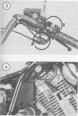
2.On models except XV1000 and XVI100, is the fuel shutoff valve in the ON position. Turn the valve to the reserve position to be sure you get the last remaining gas. See Figure 2.
3.On XV1000 and XVI100 models, make sure the fuel pump switch is on the reserve position (A, Figure 3). If there is doubt about the fuel pump operation, refer to Chapter Seven.
4.Make sure the kill switch is not stuck in the OFF position (B, Figure 3) or that the wire is not broken and shorting out.
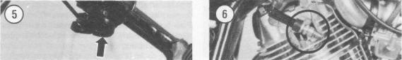
5.Are the spark plug wires (Figure 4) on tight? Push both spark plugs on and slightly rotate them to clean the electrical connection between the plug and the connector.
6.Is the choke (Figure 5) in the right position?
18 |
CHAPTER TWO |
ENGINE STARTING
An engine that refuses to start or is difficult to start is very frustrating. More often than not, the problem is very minor and can be found with a simple and logical troubleshooting approach.
The following items show a beginning point from which to isolate engine starting problems.
Engine Fails to Start
Perform the following spark test to determine if the ignition system is operating properly.
1.Remove one of the spark plugs.
2.Connect the spark plug wire and connector to the spark plug and touch the spark plug base to a good ground such as the engine cylinder head (Figure 6). Position the spark plug so you can see the electrodes.
3.Crank the engine over with the starter. A fat blue spark should be evident across the spark plug electrodes.
WARNING
Do not hold the spark plug, wire or connector or a serious electrical shock may result. If necessary, use a pair of insulated pliers to hold the spark plug or wire. The high voltage generated by the ignition system could produce serious orfatal shocks.
4. If the spark is good, check for one or more of the following possible malfunctions:
a.Obstructed fuel line or fuel filter.
b.Leaking head gasket(s).
c.Low compression.
5.If the spark is not good, check for one or more of the following:
a.Weak ignition coil(s).
b.Weak TCI module.
c.Loose electrical connections.
d.Dirty electrical connections.
e.Loose or broken ignition coil ground wire.
f.Broken or shorted high tension lead to the spark plug.
Engine is Difficult to Start
Check for one or more of the following possible malfunctions:
a.Fouled spark plug(s).
b.Improperly adjusted choke.
c.Contaminated fuel system.
d.Improperly adjusted carburetor.
e.Weak TCI module.
f.Weak ignition coil(s).
g.Poor compression.
Engine Will Not Crank
Check for one or more of the following possible malfunctions:
a.Blown fuse.
b.Discharged battery.
c.Defective starter motor.
d.Seized piston(s).
e.Seized crankshaft bearings.
f.Broken connecting rod.
g.Locked-up transmission or clutch assembly.
ENGINE PERFORMANCE
In the following check list, it is assumed that the engine runs, but is not operating at peak performance. This will serve as a starting point from which to isolate a performance malfunction.
The possible causes for each malfunction are listed in a logical sequence and in order of probability.
Engine Will Not Idle
a.Carburetor incorrectly adjusted.
b.Fouled or improperly gapped spark plug(s).
c.Leaking head gasket(s).
d.Obstructed fuel line or fuel shutoff valve.
e.Obstructed fuel filter on XV1000 and XVI100 models.
f.Ignition timing incorrect.
g.Valve clearance incorrect.
Engine Misses at High Speed
a.Fouled or improperly gapped spark plugs.
b.Improper carburetor main jet selection.
c.Ignition timing incorrect.
d.Weak ignition coil(s).
e. Obstructed fuel line or fuel shutoff valve.
f.Obstructed fuel filter on XV1000 and XVI100 models.
g.Clogged jets in carburetors.
Engine Overheating
a. Incorrect carburetor adjustment or jet selection.
 Loading...