


 (AV) 2006 Owner's manual")
OWNER’S MANUAL
XVS1100V
XVS1100AV
3B8-28199-20

INTRODUCTION
EAU10100
Welcome to the Yamaha world of motorcycling!
As the owner of the XVS1100/XVS1100A, you are benefiting from Yamaha’s vast experience and newest technology regarding the design and manufacture of high-quality products, which have earned Yamaha a reputation for dependability. Please take the time to read this manual thoroughly, so as to enjoy all advantages of your XVS1100/XVS1100A. The owner’s manual does not only instruct you in how to operate, inspect and maintain your motorcycle, but also in how to safeguard yourself and others from trouble and injury.
In addition, the many tips given in this manual will help keep your motorcycle in the best possible condition. If you have any further questions, do not hesitate to contact your Yamaha dealer.
The Yamaha team wishes you many safe and pleasant rides. So, remember to put safety first!
IMPORTANT MANUAL INFORMATION
EAU10150
Particularly important information is distinguished in this manual by the following notations:
The Safety Alert Symbol means ATTENTION! BECOME ALERT! YOUR SAFETY IS
INVOLVED!
|
|
|
|
Failure to follow WARNING instructions could result in severe injury or death to the |
|
WARNING |
|
motorcycle operator, a bystander, or a person inspecting or repairing the motor- |
|
|
|
|
|
cycle. |
|
|
|
|
|
|
|
|
|
|
|
|
|
|
A CAUTION indicates special precautions that must be taken to avoid damage to |
|
CAUTION: |
|
|
|
|
|
the motorcycle. |
||
|
|
|
|
|
|
|
|
|
|
|
|
|
|
|
|
NOTE: |
A NOTE provides key information to make procedures easier or clearer. |
||
|
|
|
|
|
NOTE:
●This manual should be considered a permanent part of this motorcycle and should remain with it even if the motorcycle is subsequently sold.
●Yamaha continually seeks advancements in product design and quality. Therefore, while this manual contains the most current product information available at the time of printing, there may be minor discrepancies between your motorcycle and this manual. If you have any questions concerning this manual, please consult your Yamaha dealer.
EWA10030
 WARNING
PLEASE READ THIS MANUAL CAREFULLY AND COMPLETELY BEFORE OPERATING THIS MOTORCYCLE.
IMPORTANT MANUAL INFORMATION
EAU10200
XVS1100V/XVS1100AV
OWNER’S MANUAL ©2005 by Yamaha Motor Co., Ltd.
1st edition, April 2005 All rights reserved.
Any reprinting or unauthorized use without the written permission of Yamaha Motor Co., Ltd.
is expressly prohibited. Printed in Japan.

TABLE OF CONTENTS
SAFETY INFORMATION .................. |
1-1 |
Adjusting the shock absorber |
|
Final gear oil ................................ |
6-10 |
Location of important labels ............ |
1-5 |
assembly ................................... |
3-16 |
Cleaning the air filter element ...... |
6-11 |
|
|
Luggage strap holders ................. |
3-19 |
Adjusting the carburetors ............. |
6-12 |
DESCRIPTION .................................. |
2-1 |
Sidestand ..................................... |
3-19 |
Adjusting the engine idling |
|
Left view .......................................... |
2-1 |
Ignition circuit cut-off system ........ |
3-20 |
speed ........................................ |
6-12 |
Right view ........................................ |
2-3 |
|
|
Checking the throttle cable |
|
Controls and instruments................. |
2-5 |
PRE-OPERATION CHECKS ............. |
4-1 |
free play .................................... |
6-13 |
|
|
Pre-operation check list .................. |
4-2 |
Valve clearance ........................... |
6-13 |
INSTRUMENT AND CONTROL |
|
|
|
Tires (XVS1100) ........................... |
6-14 |
FUNCTIONS ....................................... |
3-1 |
OPERATION AND IMPORTANT |
|
Tires (XVS1100A)......................... |
6-16 |
Immobilizer system (XVS1100A) .... |
3-1 |
RIDING POINTS................................. |
5-1 |
Spoke wheels (XVS1100)............. |
6-18 |
Main switch/steering lock |
|
Starting and warming up a cold |
|
Cast wheels (XVS1100A) ............. |
6-18 |
(XVS1100).................................... |
3-2 |
engine (XVS1100) ....................... |
5-1 |
Adjusting the clutch lever |
|
Main switch/steering lock |
|
Starting and warming up a cold |
|
free play .................................... |
6-19 |
(XVS1100A) ................................. |
3-2 |
engine (XVS1100A) ..................... |
5-2 |
Adjusting the brake lever |
|
Indicator and warning lights ............ |
3-4 |
Starting a warm engine .................. |
5-4 |
free play .................................... |
6-19 |
Speedometer unit ........................... |
3-5 |
Shifting ............................................ |
5-4 |
Adjusting the rear brake light |
|
Handlebar switches ........................ |
3-6 |
Tips for reducing fuel |
|
switch ....................................... |
6-20 |
Clutch lever ..................................... |
3-7 |
consumption ............................... |
5-5 |
Checking the front and rear |
|
Shift pedal (XVS1100) ..................... |
3-8 |
Engine break-in .............................. |
5-5 |
brake pads ................................ |
6-21 |
Shift pedal (XVS1100A)................... |
3-8 |
Parking ........................................... |
5-6 |
Checking the brake fluid level ...... |
6-21 |
Brake lever ...................................... |
3-8 |
|
|
Changing the brake fluid .............. |
6-22 |
Brake pedal ..................................... |
3-9 |
PERIODIC MAINTENANCE AND |
|
Checking and lubricating the |
|
Fuel tank cap .................................. |
3-9 |
MINOR REPAIR ................................. |
6-1 |
cables ....................................... |
6-23 |
Fuel ............................................... |
3-10 |
Owner’s tool kit ............................... |
6-1 |
Checking and lubricating the |
|
Fuel cock ...................................... |
3-11 |
Periodic maintenance and |
|
throttle grip and cable ............... |
6-23 |
Starter (choke) lever ..................... |
3-12 |
lubrication chart .......................... |
6-2 |
Checking and lubricating the |
|
Seats (XVS1100)........................... |
3-12 |
Removing and installing the |
|
brake and shift pedals .............. |
6-23 |
Seats (XVS1100A) ........................ |
3-13 |
panel ........................................... |
6-6 |
Checking and lubricating the |
|
Helmet holder ............................... |
3-15 |
Checking the spark plugs ............... |
6-6 |
brake and clutch levers ............ |
6-24 |
Storage compartment ................... |
3-15 |
Engine oil ....................................... |
6-8 |
|
|

TABLE OF CONTENTS
Checking and lubricating the |
|
sidestand ................................... |
6-24 |
Lubricating the swingarm pivots ... |
6-25 |
Lubricating the rear suspension ... |
6-25 |
Checking the front fork ................. |
6-25 |
Checking the steering ................... |
6-26 |
Checking the wheel bearings ....... |
6-27 |
Battery .......................................... |
6-27 |
Replacing the fuses ...................... |
6-28 |
Replacing the headlight bulb ........ |
6-30 |
Replacing a turn signal light bulb |
|
or the tail/brake light bulb .......... |
6-31 |
Supporting the motorcycle ............ |
6-32 |
Troubleshooting ............................ |
6-32 |
Troubleshooting chart ................... |
6-33 |
MOTORCYCLE CARE AND |
|
STORAGE .......................................... |
7-1 |
Care ................................................ |
7-1 |
Storage ........................................... |
7-3 |
SPECIFICATIONS ............................. |
8-1 |
CONSUMER INFORMATION............. |
9-1 |
Identification numbers .................... |
9-1 |
Motorcycle noise regulation |
|
(for Australia) .............................. |
9-2 |

 SAFETY INFORMATION
EAU10251
MOTORCYCLES ARE SINGLE
1TRACK VEHICLES. THEIR SAFE USE AND OPERATION ARE DEPENDENT UPON THE USE OF PROPER RIDING TECHNIQUES AS WELL AS THE EXPERTISE OF THE OPERATOR. EVERY OPERATOR SHOULD KNOW THE FOLLOWING REQUIREMENTS BEFORE RIDING THIS MOTORCYCLE.
HE OR SHE SHOULD:
●OBTAIN THOROUGH INSTRUCTIONS FROM A COMPETENT SOURCE ON ALL ASPECTS OF MOTORCYCLE OPERATION.
●OBSERVE THE WARNINGS AND MAINTENANCE REQUIREMENTS IN THE OWNER’S MANUAL.
●OBTAIN QUALIFIED TRAINING IN SAFE AND PROPER RIDING TECHNIQUES.
●OBTAIN PROFESSIONAL TECHNICAL SERVICE AS INDICATED BY THE OWNER’S MANUAL
AND/OR WHEN MADE NECESSARY BY MECHANICAL CONDITIONS.
Safe riding
●Always make pre-operation checks. Careful checks may help prevent an accident.
●This motorcycle is designed to carry the operator and a passenger.
●The failure of motorists to detect and recognize motorcycles in traffic is the predominating cause of automobile/motorcycle accidents. Many accidents have been caused by an automobile driver who did not see the motorcycle. Making yourself conspicuous appears to be very effective in reducing the chance of this type of accident.
Therefore:
•Wear a brightly colored jacket.
•Use extra caution when approaching and passing through intersections, since intersections are the most likely places for motorcycle accidents to occur.
•Ride where other motorists can see you. Avoid riding in another motorist’s blind spot.
●Many motorcycle accidents involve inexperienced operators. In fact, many operators who have been involved in accidents do not even have a current motorcycle license.
•Make sure that you are qualified and that you only lend your motorcycle to other qualified operators.
•Know your skills and limits. Staying within your limits may help you to avoid an accident.
•We recommend that you practice riding your motorcycle where there is no traffic until you have become thoroughly familiar with the motorcycle and all of its controls.
●Many motorcycle accidents have been caused by error of the motorcycle operator. A typical error made by the operator is veering
1-1

 SAFETY INFORMATION
wide on a turn due to EXCESSIVE SPEED or undercornering (insufficient lean angle for the speed).
•Always obey the speed limit and never travel faster than warranted by road and traffic conditions.
•Always signal before turning or changing lanes. Make sure that other motorists can see you.
●The posture of the operator and passenger is important for proper control.
•The operator should keep both hands on the handlebar and both feet on the operator footrests during operation to maintain control of the motorcycle.
•The passenger should always hold onto the operator, seat strap, or grab bar, if equipped, with both hands and keep both feet on the passenger footrests.
•Never carry a passenger unless he or she can firmly place both feet on the passenger footrests.
●Never ride under the influence of alcohol or other drugs.
●This motorcycle is designed for onroad use only, therefore, it is not suitable for off-road use.
Protective apparel
The majority of fatalities from motorcycle accidents are the result of head injuries. The use of a safety helmet is the single most critical factor in the prevention or reduction of head injuries.
●Always wear an approved helmet.
●Wear a face shield or goggles. Wind in your unprotected eyes could contribute to an impairment of vision which could delay seeing a hazard.
●The use of a jacket, heavy boots, trousers, gloves, etc., is effective in preventing or reducing abrasions or lacerations.
●Never wear loose-fitting clothes, otherwise they could catch on the control levers, footrests, or wheels and cause injury or an accident.
●Never touch the engine or exhaust system during or after operation. They become very hot and can
cause burns. Always wear protective clothing that covers your legs, ankles, and feet.
● Passengers should also observe 1 the precautions mentioned above.
Modifications
Modifications made to this motorcycle not approved by Yamaha, or the removal of original equipment, may render the motorcycle unsafe for use and may cause severe personal injury. Modifications may also make your motorcycle illegal to use.
Loading and accessories
Adding accessories or cargo to your motorcycle can adversely affect stability and handling if the weight distribution of the motorcycle is changed. To avoid the possibility of an accident, use extreme caution when adding cargo or accessories to your motorcycle. Use extra care when riding a motorcycle that has added cargo or accessories. Here are some general guidelines to follow if loading cargo or adding accessories to your motorcycle:
1-2
 SAFETY INFORMATION
Loading
The total weight of the operator, passenger, accessories and cargo must
1 not exceed the maximum load limit.
Maximum load:
XVS1100 200 kg (441 lb)
XVS1100A 203 kg (448 lb)
When loading within this weight limit, keep the following in mind:
●Cargo and accessory weight should be kept as low and close to the motorcycle as possible. Make sure to distribute the weight as evenly as possible on both sides of the motorcycle to minimize imbalance or instability.
●Shifting weights can create a sudden imbalance. Make sure that accessories and cargo are securely attached to the motorcycle before riding. Check accessory mounts and cargo restraints frequently.
●Never attach any large or heavy items to the handlebar, front fork, or front fender. These items, including such cargo as sleeping
bags, duffel bags, or tents, can create unstable handling or slow steering response.
Accessories
Genuine Yamaha accessories have been specifically designed for use on this motorcycle. Since Yamaha cannot test all other accessories that may be available, you must personally be responsible for the proper selection, installation and use of non-Yamaha accessories. Use extreme caution when selecting and installing any accessories.
Keep the following guidelines in mind, as well as those provided under “Loading” when mounting accessories.
●Never install accessories or carry cargo that would impair the performance of your motorcycle. Carefully inspect the accessory before using it to make sure that it does not in any way reduce ground clearance or cornering clearance,
limit suspension travel, steering travel or control operation, or obscure lights or reflectors.
•Accessories fitted to the handlebar or the front fork area can create instability due to improper weight distribution or aerodynamic changes. If accessories are added to the handlebar or front fork area, they must be as lightweight as possible and should be kept to a minimum.
•Bulky or large accessories may seriously affect the stability of the motorcycle due to aerodynamic effects. Wind may attempt to lift the motorcycle, or the motorcycle may become unstable in cross winds. These accessories may also cause instability when passing or being passed by large vehicles.
•Certain accessories can displace the operator from his or her normal riding position. This improper position limits the freedom of movement of the opera-
1-3
 SAFETY INFORMATION
tor and may limit control ability, therefore, such accessories are not recommended.
●Use caution when adding electrical accessories. If electrical accessories exceed the capacity of the motorcycle’s electrical system, an electric failure could result, which could cause a dangerous loss of lights or engine power.
Gasoline and exhaust gas
●GASOLINE IS HIGHLY FLAMMABLE:
•Always turn the engine off when refueling.
•Take care not to spill any gasoline on the engine or exhaust system when refueling.
•Never refuel while smoking or in the vicinity of an open flame.
●Never start the engine or let it run for any length of time in a closed area. The exhaust fumes are poisonous and may cause loss of consciousness and death within a short time. Always operate your motorcycle in an area that has adequate ventilation.
●Always turn the engine off before leaving the motorcycle unattended and remove the key from the main switch. When parking the motorcycle, note the following:
•The engine and exhaust system may be hot, therefore, park the motorcycle in a place where pedestrians or children are not likely to touch these hot areas.
•Do not park the motorcycle on a slope or soft ground, otherwise it may fall over.
•Do not park the motorcycle near a flammable source (e.g. a kerosene heater, or near an open flame), otherwise it could catch fire.
●When transporting the motorcycle in another vehicle, make sure that it is kept upright and that the fuel cock is turned to “ON” or “RES” (for vacuum type) / “OFF” (for manual type). If it should lean over, gasoline may leak out of the carburetor or fuel tank.
●If you should swallow any gasoline, inhale a lot of gasoline vapor, or allow gasoline to get into your
1-4
eyes, see your doctor immediately. If any gasoline spills on your skin or clothing, immediately wash the
affected area with soap and water 1 and change your clothes.
 SAFETY INFORMATION
EAU10381
Location of important labels
Please read the following important labels carefully before operating this vehicle.
1
1 2
3
1-5

 SAFETY INFORMATION
1 |
|
|
3 |
XVS1100 |
|
1 |
|
|
|
Before you operate this vehicle, |
|
|
|
||
|
|
|
|
|
|
||
|
|
read the owner’s manual. |
|
|
|
|
|
|
|
Prima di usare il veicolo, |
|
|
|
|
|
|
|
leggete il manuale di istruzioni. |
|
|
|
|
|
|
|
Lire le manuel du propriétaire |
|
|
|
|
|
|
|
avant |
d’utiliser ce véhicule. |
|
|
|
|
|
|
Lesen Sie die Bedienungsanleitung |
|
|
|
|
|
|
|
bevor Sie dieses Fahrzeug fahren. |
|
|
|
|
|
|
|
Antes de conducir este vehículo, |
|
|
|
|
|
|
|
lea el Manual del Propietario. |
|
|
|
|
|
|
|
|
5RU-21568-00 |
|
|
|
|
2 |
3 XVS1100A |
1-6
DESCRIPTION
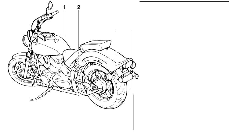
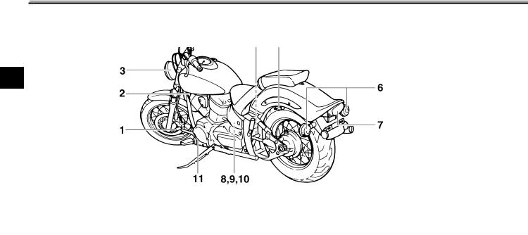
Left view
XVS1100
2
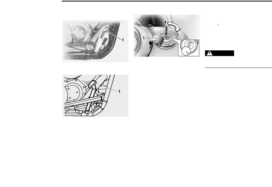
1.Shift pedal (page 3-8)
2.Fuel cock (page 3-11)
3.Headlight (page 6-30)
4.Shock absorber assembly spring preload adjusting ring (page 3-16)
5.Helmet holder (page 3-15)
6.Rear turn signal light (page 6-31)
7.Tail/brake light (page 6-31)
8.Storage compartment (page 3-15)
9.Owner’s tool kit (page 6-1)
10.Fuse box (page 6-28)
EAU32220
11.Engine oil level check window (page 6-8)
2-1
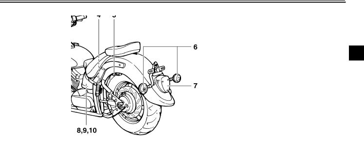
DESCRIPTION
XVS1100A
2
1.Shift pedal (page 3-8)
2.Fuel cock (page 3-11)
3.Headlight (page 6-30)
4.Shock absorber assembly spring preload adjusting ring (page 3-16)
5.Helmet holder (page 3-15)
6.Rear turn signal light (page 6-31)
7.Tail/brake light (page 6-31)
8.Storage compartment (page 3-15)
9.Owner’s tool kit (page 6-1)
10.Fuse box (page 6-28)
11.Engine oil level check window (page 6-8)
2-2
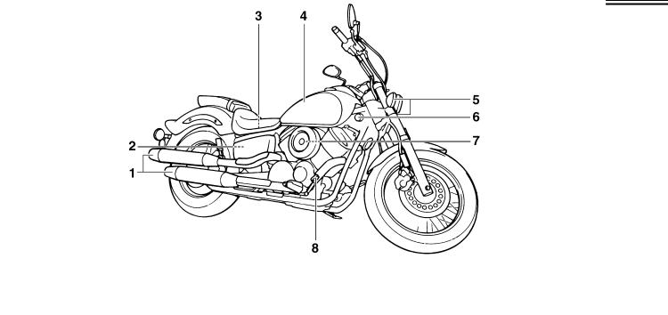
DESCRIPTION
EAU32230
Right view
XVS1100
2
1.Muffler
2.Battery (page 6-27)
3.Main fuse (page 6-28)
4.Fuel tank (page 3-9)
5.Front turn signal light (page 6-31)
6.Main switch/steering lock (page 3-2)
7.Air filter element (page 6-11)
8.Brake pedal (page 3-9)
2-3
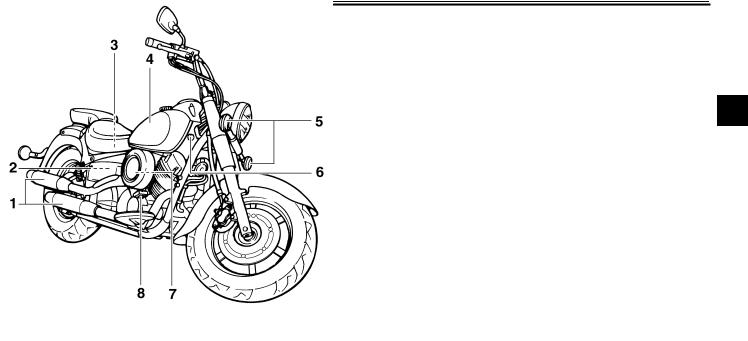
DESCRIPTION
XVS1100A
2
1.Muffler
2.Battery (page 6-27)
3.Main fuse (page 6-28)
4.Fuel tank (page 3-9)
5.Front turn signal light (page 6-31)
6.Main switch/steering lock (page 3-2)
7.Air filter element (page 6-11)
8.Brake pedal (page 3-9)
2-4
DESCRIPTION
EAU10430
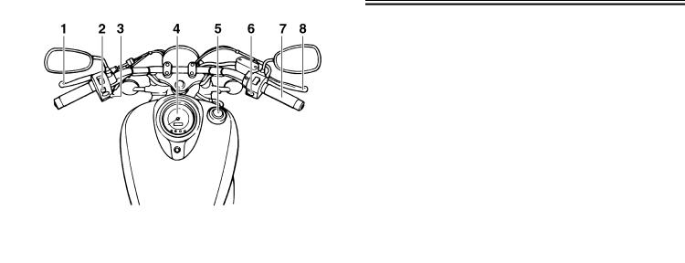
Controls and instruments
2
1.Clutch lever (page 3-7)
2.Left handlebar switches (page 3-6)
3.Starter (choke) lever (page 3-12)
4.Speedometer unit (page 3-5)
5.Fuel tank cap (page 3-9)
6.Right handlebar switches (page 3-6)
7.Throttle grip (page 6-13)
8.Brake lever (page 3-8)
2-5
INSTRUMENT AND CONTROL FUNCTIONS
EAU26890
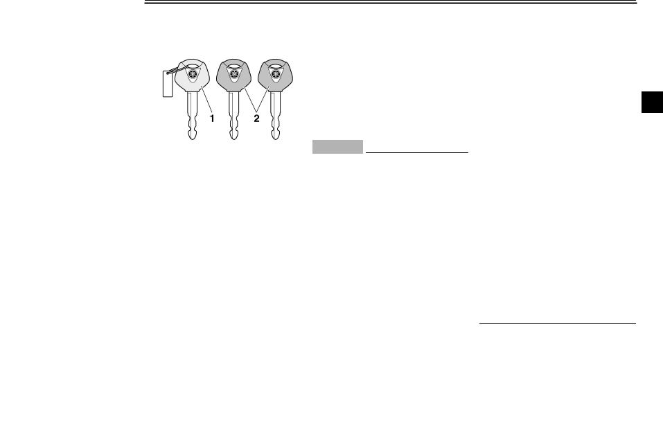
Immobilizer system (XVS1100A)
1.Code re-registering key (red bow)
2.Standard keys (black bow)
This vehicle is equipped with an immobilizer system to help prevent theft by re-registering codes in the standard keys. This system consists of the following.
●a code re-registering key (with a red bow)
●two standard keys (with a black bow) that can be re-registered with new codes
●a transponder (which is installed in the code re-registering key)
●an immobilizer unit
●the ignitor unit
● an immobilizer system indicator light (See page 3-4.)
The key with the red bow is used to register codes in each standard key. Since re-registering is a difficult process, take the vehicle along with all three keys to a Yamaha dealer to have them re-reg- istered. Do not use the key with the red bow for driving. It should only be used for re-registering the standard keys. Always use a standard key for driving.
ECA11820
CAUTION:
●DO NOT LOSE THE CODE REREGISTERING KEY! CONTACT YOUR DEALER IMMEDIATELY IF IT IS LOST! If the code re-reg- istering key is lost, registering new codes in the standard keys is impossible. The standard keys can still be used to start the vehicle, however if code reregistering is required (i.e., if a new standard key is made or all keys are lost) the entire immobilizer system must be replaced. Therefore, it is highly recom-
mended to use either standard key and keep the code re-regis- tering key in a safe place.
●Do not submerse any key in water.
●Do not expose any key to excessively high temperatures.
●Do not place any key close to
magnets (this includes, but not |
3 |
limited to, products such as |
|
speakers, etc.). |
|
●Do not place heavy items on any key.
●Do not grind any key or alter its shape.
●Do not disassemble the plastic part of any key.
●Do not put two keys of any immobilizer system on the same key ring.
●Keep the standard keys as well as keys of other immobilizer systems away from this vehicle’s code re-registering key.
●Keep other immobilizer system keys away from the main switch as they may cause signal interference.
3-1
INSTRUMENT AND CONTROL FUNCTIONS
EAU10460
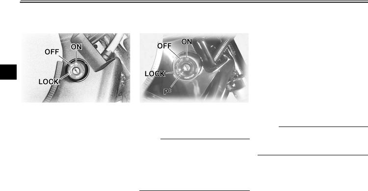
Main switch/steering lock (XVS1100)
3
The main switch/steering lock controls the ignition and lighting systems, and is used to lock the steering. The various positions are described below.
EAU10471
Main switch/steering lock (XVS1100A)
The main switch/steering lock controls the ignition and lighting systems, and is used to lock the steering.
NOTE:
Be sure to use the standard key (black bow) for regular use of the vehicle. To minimize the risk of losing the code reregistering key (red bow), keep it in a safe place and only use it for code reregistering.
EAU10480
ON (XVS1100)
All electrical systems are supplied with power, and the headlight, meter lighting and taillight come on, and the engine can be started. The key cannot be removed.
EAU10570
ON (XVS1100A)
All electrical circuits are supplied with power; the meter lighting, taillight and auxiliary light come on, and the engine can be started. The key cannot be removed.
NOTE:
The headlight comes on automatically when the engine is started and stays on until the key is turned to “OFF”.
EAU10660
OFF
All electrical systems are off. The key can be removed.
EAU10680
LOCK
The steering is locked, and all electrical systems are off. The key can be removed.
3-2
INSTRUMENT AND CONTROL FUNCTIONS
To lock the steering
1.Push.
2.Turn.
1.Turn the handlebars all the way to the left.
2.Push the key in from the “OFF” position, and then turn it to “LOCK” while still pushing it.
3.Remove the key.
To unlock the steering
1.Push.
2.Turn.
Push the key in, and then turn it to “OFF” while still pushing it.
EWA10060
 WARNING
Never turn the key to “OFF” or “LOCK” while the vehicle is moving, otherwise the electrical systems will be switched off, which may result in loss of control or an accident. Make sure that the vehicle is stopped before turning the key to “OFF” or “LOCK”.
EAU10920 |
|
(Parking) (XVS1100A) |
|
The steering is locked, the taillight and |
|
auxiliary light are on, and the hazard |
|
light can be turned on, but all other |
|
electrical systems are off. The key can |
|
be removed. |
|
The steering must be locked before the |
|
key can be turned to “ ”. |
3 |
ECA11020
CAUTION:
Do not use the parking position for an extended length of time, otherwise the battery may discharge.
3-3
INSTRUMENT AND CONTROL FUNCTIONS
EAU11003
Indicator and warning lights
3
1.Oil level warning light “ 

 ”
”
2.Neutral indicator light “  ”
”
3.Turn signal indicator light “ ”
”
4.Engine trouble warning light “  ”
”
5.Immobilizer system indicator light “  ” (XVS1100A)
6.High beam indicator light “  ”
”
EAU11020
Turn signal indicator light “ ”
”
This indicator light flashes when the turn signal switch is pushed to the left or right.
EAU11060
Neutral indicator light “ ”
”
This indicator light comes on when the transmission is in the neutral position.
EAU11080
High beam indicator light “ ”
”
This indicator light comes on when the high beam of the headlight is switched on.
EAU11120
Oil level warning light “

 ”
”
This warning light comes on when the engine oil level is low.
The electrical circuit of the warning light can be checked by turning the key to “ON”.
If the warning light does not come on for a few seconds, then go off, have a Yamaha dealer check the electrical circuit.
NOTE:
Even if the oil level is sufficient, the warning light may flicker when riding on a slope or during sudden acceleration or deceleration, but this is not a malfunction.
EAU11500
Engine trouble warning light “  ”
”
This warning light comes on or flashes when an electrical circuit monitoring the engine is defective. When this occurs, have a Yamaha dealer check the selfdiagnosis system.
The electrical circuit of the warning light can be checked by turning the key to “ON”. If the warning light does not come on for a few seconds, then go off, have a Yamaha dealer check the electrical circuit.
EAU27020
Immobilizer system indicator light “  ” (XVS1100A)
The electrical circuit of the indicator light can be checked by turning the key to “ON”.
If the indicator light does not come on for a few seconds, then go off, have a Yamaha dealer check the electrical circuit.
When the key is turned to “OFF” and 30 seconds have passed, the indicator light will start flashing indicating the immobilizer system is enabled. After 24
3-4
INSTRUMENT AND CONTROL FUNCTIONS
hours have passed, the indicator light will stop flashing, however the immobilizer system is still enabled.
NOTE:
This model is also equipped with a selfdiagnosis device for the immobilizer system. If the immobilizer system is defective, the indicator light will start flashing a pattern when the key is turned to “ON”. When this occurs, have a Yamaha dealer check the self-diagno- sis system. However, if the indicator light slowly flashes five times, and then quickly flashes two times repeatedly, this error could be caused by signal interference. If this occurs, try the following.
1.Use the code re-registering key to start the engine.
NOTE:
Make sure there are no other immobilizer keys close to the main switch, and do not keep more than one immobilizer key on the same key ring! Immobilizer system keys may cause signal interference, which may prevent the engine from starting.
2. If the engine starts, turn it off, and |
EAU11731 |
|
try starting the engine with the |
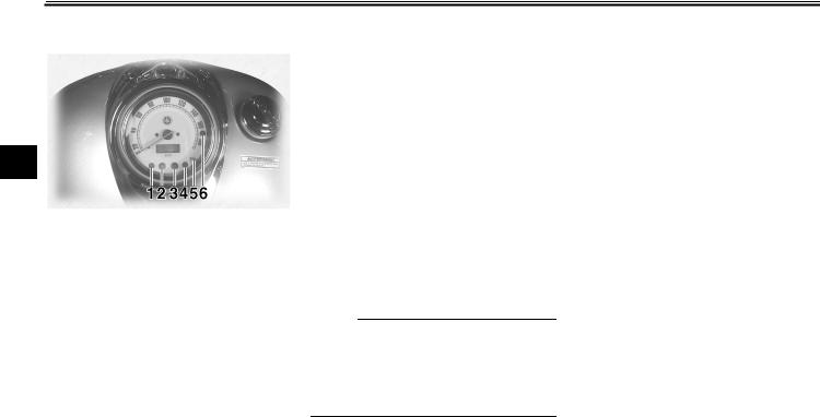
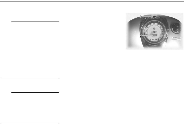
Speedometer unit |
|||
|
|
|
|
|
standard keys. |
|
|
|
|
3. If one or both of the standard keys |
|
|
|
|
do not start the engine, take the |
|
|
|
|
vehicle, the code re-registering |
|
|
|
|
key and both standard keys to a |
|
|
|
|
Yamaha dealer and have the stan- |
|
|
|
|
|
|
3 |
|
|
dard keys re-registered. |
|
|
|
|
|
|
|
|
|
|
|
|
|
|
|
1. “TRIP” button |
|||
|
2. Odometer/tripmeter |
|||
|
The speedometer unit is equipped with |
|||
|
a digital odometer and a tripmeter. The |
|||
|
speedometer shows riding speed. The |
|||
|
odometer shows the total distance trav- |
|||
|
eled. The tripmeter shows the distance |
|||
|
traveled since it was last set to zero. |
|||
|
Pushing the “TRIP” button switches the |
|||
|
display between the odometer mode |
|||
|
“ODO” and the tripmeter mode “TRIP”. |
|||
|
To reset the tripmeter, select it by push- |
|||
|
ing the “TRIP” button, and then push |
|||
|
the “TRIP” button again and hold it |
|||
|
down for at least one second. The trip- |
|||
|
meter can be used to estimate the dis- |
|||
3-5
INSTRUMENT AND CONTROL FUNCTIONS
tance that can be traveled with a full tank of fuel. This information will enable you to plan future fuel stops.
3
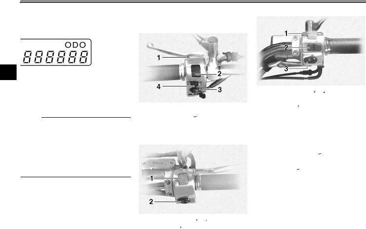
Handlebar switches |
EAU12343 |
Right (XVS1100A) |
|
||
|
|
|
Left |
|
|
NOTE:
This model is not equipped with a tachometer; however, it has a built-in speed limiter, which prevents the engine speed from exceeding approximately 6800 r/min and the vehicle speed from exceeding approximately 175 km/h (110 mi/h).
1.Pass switch “  ”
”
2.Dimmer switch “  /
/ ”
”
3.Horn switch “  ”
”
4.Turn signal switch “ /
/ ”
”
Right (XVS1100)
1.Engine stop switch “ /
/ ”
”
2.Start switch “ ”
”
1.Engine stop switch “ /
/ ”
”
2.Hazard switch “ ”
”
3.Start switch “ ”
”
EAU12350
Pass switch “ ”
”
Press this switch to flash the headlight.
EAU12400
Dimmer switch “ /
/ ”
”
Set this switch to “ ” for the high beam and to “
 ” for the low beam.
EAU12460
Turn signal switch “ /
/ ”
”
To signal a right-hand turn, push this switch to “ ”. To signal a left-hand turn, push this switch to “
 ”. When released, the switch returns to the center
3-6
INSTRUMENT AND CONTROL FUNCTIONS
position. To cancel the turn signal lights, push the switch in after it has returned to the center position.
EAU12500
Horn switch “  ”
”
Press this switch to sound the horn.
EAU12660
Engine stop switch “ /
/ ”
”
Set this switch to “ ” before starting the engine. Set this switch to “
 ” to stop the engine in case of an emergency, such as when the vehicle overturns or when the throttle cable is stuck.
EAU12710
Start switch “ ”
”
Push this switch to crank the engine with the starter.
ECA10050
CAUTION:
See page 5-1 for starting instructions prior to starting the engine.
EAU12732
Hazard switch “ ” (XVS1100A)
With the key in the “ON” or “ ” position, use this switch to turn on the hazard light (simultaneous flashing of all turn signal lights).
The hazard light is used in case of an emergency or to warn other drivers when your vehicle is stopped where it might be a traffic hazard.
ECA10061
CAUTION:
Do not use the hazard lights for an extended length of time with the engine not running, otherwise the battery may discharge.
EAU12820
Clutch lever
3
1. Clutch lever
The clutch lever is located at the left handlebar grip. To disengage the clutch, pull the lever toward the handlebar grip. To engage the clutch, release the lever. The lever should be pulled rapidly and released slowly for smooth clutch operation.
The clutch lever is equipped with a clutch switch, which is part of the ignition circuit cut-off system. (See page 3-20.)
3-7
INSTRUMENT AND CONTROL FUNCTIONS
EAU12870 |
EAU12880 |
EAU12890 |
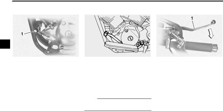
Shift pedal (XVS1100) |
Shift pedal (XVS1100A) |
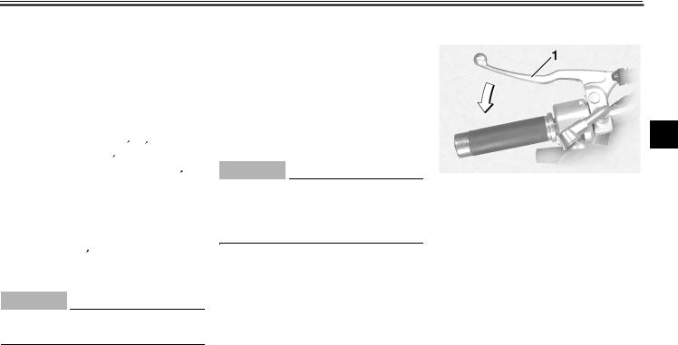
Brake lever |
3
1. Shift pedal
The shift pedal is located on the left side of the engine and is used in combination with the clutch lever when shifting the gears of the 5-speed con- stant-mesh transmission equipped on this motorcycle.
1. Shift pedal
The shift pedal is located on the left side of the engine and is used in combination with the clutch lever when shifting the gears of the 5-speed con- stant-mesh transmission equipped on this motorcycle.
NOTE:
Use your toes or heel to shift up and your toes to shift down.
1. Brake lever
The brake lever is located at the right handlebar grip. To apply the front brake, pull the lever toward the handlebar grip.
3-8
INSTRUMENT AND CONTROL FUNCTIONS
EAU12941
Brake pedal
XVS1100
1. Brake pedal
XVS1100A
1. Brake pedal
The brake pedal is on the right side of the motorcycle. To apply the rear brake, press down on the brake pedal.
EAU13120
Fuel tank cap
1.Fuel tank cap lock cover
2.“ ” mark
3.Unlock.
4.Lock.
To remove the fuel tank cap
Slide the lock cover open, insert the key into the lock, and then turn it 1/4 turn clockwise. The lock will be released and the fuel tank cap can be removed.
To install the fuel tank cap
1.Insert the fuel tank cap into the tank opening with the key inserted
in the lock and with the “ ” mark facing forward.
2.Turn the key counterclockwise to the original position, remove it, and then close the lock cover.
NOTE: |
|
|
|
|
The fuel tank cap cannot be installed |
|
|||
unless the key is in the lock. In addition, |
|
|||
the key cannot be removed if the cap is |
|
|||
not properly installed and locked. |
3 |
|||
|
|
|
|
|
|
|
EWA10130 |
|
|
|
||||
WARNING |
|
|
|
|
Make sure that the fuel tank cap is properly installed before riding.
3-9
INSTRUMENT AND CONTROL FUNCTIONS
EAU13210
Fuel
3
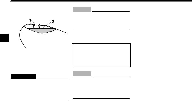
1.Fuel tank filler tube
2.Fuel level
Make sure that there is sufficient fuel in the tank. Fill the fuel tank to the bottom of the filler tube as shown.
EWA10880
 WARNING
●Do not overfill the fuel tank, otherwise it may overflow when the fuel warms up and expands.
●Avoid spilling fuel on the hot engine.
ECA10070
CAUTION:
Immediately wipe off spilled fuel with a clean, dry, soft cloth, since fuel may deteriorate painted surfaces or plastic parts.
EAU13330
Recommended fuel:
UNLEADED GASOLINE ONLY
Fuel tank capacity:
17.0 L (4.49 US gal) (3.74 Imp.gal)
Fuel reserve amount:
4.5 L (1.19 US gal) (0.99 Imp.gal)
ECA11400
CAUTION:
Use only unleaded gasoline. The use of leaded gasoline will cause severe damage to internal engine parts, such as the valves and piston rings, as well as to the exhaust system.
Your Yamaha engine has been designed to use regular unleaded gasoline with a research octane number of 91 or higher. If knocking (or pinging) occurs, use a gasoline of a different brand
or premium unleaded fuel. Use of unleaded fuel will extend spark plug life and reduce maintenance costs.
3-10
INSTRUMENT AND CONTROL FUNCTIONS
EAU13550
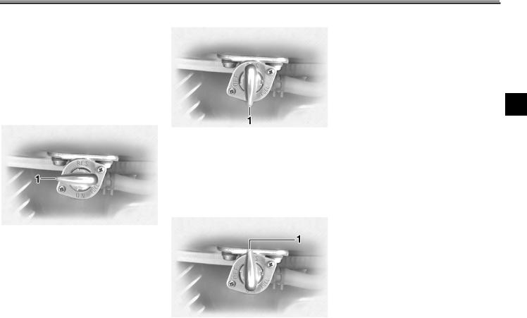
Fuel cock
The fuel cock supplies fuel from the tank to the carburetors while also filtering it.
The fuel cock lever positions are explained as follows and shown in the illustrations.
OFF
1. Pointed end positioned over “OFF”
With the fuel cock lever in this position, fuel will not flow. Always turn the fuel cock lever to this position when the engine is not running.
ON
1. Pointed end positioned over “ON”
With the fuel cock lever in this position, fuel flows to the carburetors. Turn the fuel cock lever to this position when starting the engine and riding.
RES
This indicates reserve. With the fuel cock lever in this position, the fuel reserve is made available. Turn the fuel cock lever to this position if you run out of fuel while riding. When this occurs, refuel as soon as possible and be sure to turn the fuel cock lever back to “ON”!
3
1. Pointed end positioned over “RES”
3-11
 Loading...