


 Loading...
2010
ASSEMBLY MANUAL
XT1200Z(Z)
23P-28107-E0
EAA00030
FOREWORD
This Assembly Manual contains the information required for the correct assembly of this Yamaha vehicle prior to delivery to the customer. Since some external parts of the vehicle have been removed at the Yamaha factory for the convenience of packing, assembly by the Yamaha dealer is required. It should be noted that the assembled vehicle should be thoroughly cleaned, checked, and adjusted prior to delivery to the customer.
EAA00050
IMPORTANT
The service specifications given in this assembly manual are based on the model as manufactured. Yamaha Motor Company, Ltd. is continually striving to improve all of its models. Modifications and significant changes in specifications or procedures will be forwarded to all authorized Yamaha dealers and will appear in future editions of this manual where applicable.
The procedures below are described in the order that the procedures are carried out correctly and completely. Failure to do so can result in poor performance and possible harm to the vehicle and/or rider.
Particularly important information is distinguished in this manual by the following notations.
This is the safety alert symbol. It is used to alert you to potential personal injury hazards. Obey all safety messages that follow this symbol to avoid possible injury or death.
WARNING |
A WARNING indicates a hazardous situation which, if not avoided, could |
|
result in death or serious injury. |
||
|
||
NOTICE |
A NOTICE indicates special precautions that must be taken to avoid dam- |
|
age to the vehicle or other property. |
||
|
TIP |
A TIP provides key information to make procedures easier or clearer. |
|
|
EAA00020
XT1200Z(Z)
ASSEMBLY MANUAL ©2010 by Yamaha Motor Co., Ltd.
First edition, February 2010 All rights reserved.
Any reproduction or unauthorized use without the written permission of Yamaha Motor Co.,Ltd.
is expressly prohibited.

EAA00060
SYMBOLS USED IN THE ASSEMBLY MANUAL
In order to simplify descriptions in this assembly manual, the following symbols are used:
SYMBOL |
DEFINITION |
SYMBOL |
DEFINITION |
|
Filling fluid |
|
Coat with lithium-soap-based grease. |
|
Lubricant |
10 |
Tighten to 10 Nm. |
|
(10 Nm = 1.0 m·kgf, 7.2 ft·lbf) |
||
|
|
||
|
Special tool |
FWD |
Towards the front of the vehicle |
|
Tightening torque |
|
Clearance required |
T |
|
|
|
. |
|
|
|
R |
|
|
|
. |
|
|
|
Wear limit, clearance
UP Install so that the arrow mark faces upward.
|
|
|
Engine speed |
Apply motor oil. |
|
|
|
|
|
|
|
|
|
|
|
|
|
|
|
Electrical data |
|
|
|
Made of rubber or plastics |
|
|
|
|
A: Ref. No. (indicating the order of operations.) |
||
|
|
|
B: Part name |
||
|
|
|
C: Quantity of parts per vehicle |
||
|
|
|
D: Place where parts are held |
||
|
|
|
(1): Refer to “PARTS LOCATION”. |
||
|
|
|
V: Stored in plastic bag |
||
|
|
|
C: Stored in carton box |
||
|
|
|
S: Fixed inside the steel frame and/or con- |
||
|
|
|
|
tained in the Styrofoam tray (upper or |
|
d |
|
D d |
|
lower) |
|
|
|
|
*: Temporarily installed or secured |
||
|
|
|
Example: |
||
|
|
|
(1)-V |
||
d |
D |
d |
(1) signifies the location of the parts and V sig- |
||
nifies that the part is stored in a plastic bag. |
|||||
|
|
|
|||
|
|
|
E: Size or material of parts |
||
|
|
|
d/D: Diameter of part |
||
|
|
|
: |
Length of part |
|
|
|
|
e.g., 5 (0.20) = 5 mm (0.20 in) |
||
EAA00070
PREPARATION
To assemble the vehicle correctly, supplies (e.g. oils, greases, and shop rags) and sufficient working space are required.
Workshop
The workshop where the vehicle is assembled should be clean, spacious, and have a level floor.
Self-protection
Protect your eyes with suitable safety glasses or goggles when using compressed air, when grinding or when doing any operation which may cause particles to fly off.
Protect hands and feet by wearing safety gloves and shoes.
EAA00080
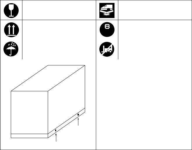
SYMBOLS USED ON TRANSPORT PACKAGE COVER
Contents of the transport package are fragile, therefore the package
Do not step anywhere on the trans-
must be handled with care.
port package.
Indicates correct upright position of |
|
|
Up to 6 of the transport packages can |
the transport package. |
|
|
be piled up. |
|
|
||
|
|
||
|
|
||
|
|
|
|
|
|
|
|
Transport package must be kept |
|
|
Insertion of the forklift arms from this |
away from rain. |
|
|
side can cause damage. |
|
|
|
|
|
Yellow labels (1) |
||
|
Lift arm insertion positions |
||
|
If the forklift arms cannot be inserted under the |
||
|
transport package in alignment with the two yel- |
||
|
low labels, adjust the arms so that they are posi- |
||
|
tioned evenly in relation to these marks while |
||
|
taking care not to damage the package contents. |
||
(1)
(1)
 ASSEMBLY MANUALS")
EAA00090
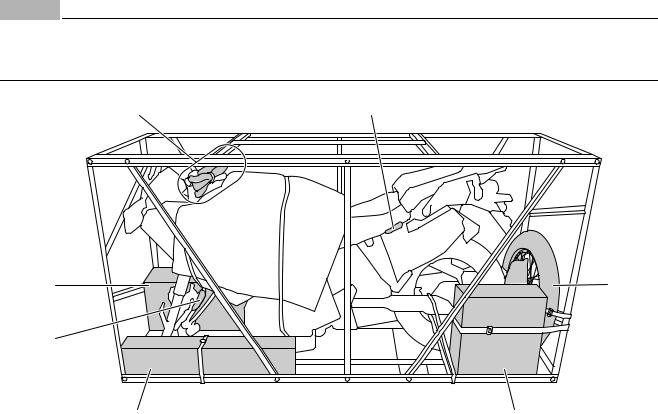
UNPACKING
1. Remove the frame cover “1”.
 1
1
2. Remove the bolts “2” and bracket “3”.
2
2
3
3. Remove the bands “4”.
A
4
B
4
A.Left side
B.Right side
4.Remove the packing frames “5”. (Lift up and then move to the side.)
TIP
Remove the bolts while holding the frame.
5
5 |
5 |
5. Remove the bolts “6” and holder “7”.
6 |
7 |
TIP
Before starting the assembly, check for damaged or missing parts. Check both the parts contained in the carton boxes and on the vehicle for damage, scratches, and other defects.
1
EAA00101
PARTS LOCATION
NOTICE
•Do not use a cutter, scissors, or other sharp object to open the carton boxes; otherwise, the included parts could be damaged.
•Wear suitable protective gear such as gloves when handling and opening the carton boxes.
1,2,3,4,5 |
7 |
8 |
11 |
6 |
|
9 |
10 |
1.Bubble wrap pack 1
2.Bubble wrap pack 2
3.Bubble wrap pack 3
4.Bubble wrap pack 4
5.Bubble wrap pack 5
6.Plastic bag
7.Plastic bag
8.Carton box 1
9.Carton box 2 10.Carton box 3 11.Front wheel
2

EAA00110
(1) Bubble wrap pack 1
1
1.Right handlebar switch
(2)Bubble wrap pack 2
1
1.Throttle grip and throttle cable housing assembly
(3)Bubble wrap pack 3
1
1.Front brake master cylinder
(4)Bubble wrap pack 4
1
1. Left handlebar switch
(5) Bubble wrap pack 5
1
1.Clutch master cylinder
(6)Plastic bag
1
1.Front wheel sensor
(7)Plastic bag
1
1. ABS test coupler
3

(8) Carton box 1 |
|
1. |
Front fender |
|
||
1 |
|
2 |
2. |
Rearview mirrors |
||
|
3. |
Left hand shield |
||||
|
|
|
4. |
Right hand shield |
||
|
|
|
5. |
Engine guard |
|
|
|
|
|
6. |
Owner’s manual |
||
3 |
|
4 |
7. |
Grip ends |
|
|
|
8. |
Plastic bag |
|
|||
|
|
|
|
|||
|
|
|
9. |
Windshield brackets |
||
|
|
|
10.Hand shield upper brackets |
|||
5 |
|
6 |
11.Hand shield lower brackets |
|||
|
12.Plastic holder |
|
||||
|
|
|
|
|||
|
|
|
13.Plastic locking tie |
|||
|
|
|
14.Plastic bag |
|
||
7 |
|
|
15.Hexagon socket bolts (grip end) |
|||
|
|
|
[d = 8 (0.31), |
= 60 (2.36)] |
||
|
|
|
16.Hexagon socket bolts (front fender) |
|||
|
|
|
|
[d = 6 (0.24), |
= 22 (0.87)] |
|
8 |
|
|
17.Hexagon socket bolt (front fender) |
|||
9 |
10 |
11 |
|
[d = 6 (0.24), |
= 30 (1.18)] |
|
|
|
|
18.Self-locking nut (front fender) |
|||
|
|
|
|
[d = 6 (0.24)] |
|
|
|
|
|
19.Nut shields (windshield) |
|||
12 |
13 |
|
|
[d = 5 (0.20)] |
|
|
|
20.Screws (windshield) |
|||||
|
|
|
||||
|
|
|
|
[d = 5 (0.20), |
= 20 (0.79)] |
|
|
|
|
21.Hexagon socket bolts (hand shields) |
|||
|
|
|
|
[d = 5 (0.20), |
= 10 (0.40)] |
|
14 |
|
|
22.Collars (hand shield upper side) |
|||
|
|
|
[d = 5.5 (0.22), D = 16 (0.63)] |
|||
15 |
16 |
17 |
|
|||
23.Collars (hand shield lower side) |
||||||
|
|
|
||||
|
|
|
|
[d = 5 (0.20), D = 12 (0.47)] |
||
|
|
|
24.Collars (grip end side) |
|||
18 |
19 |
20 |
|
[d = 8 (0.31), D = 20 (0.79)] |
||
25.Cap nuts (engine guard) |
||||||
|
|
|
|
[d = 6 (0.24)] |
|
|
|
|
|
26.Hexagon socket bolts (engine guard) |
|||
|
|
|
|
[d = 6 (0.24), |
= 32 (1.26)] |
|
21 |
22 |
23 |
27.Plastic bag |
|
||
28.Reflector assembly (right side) (for AUS) |
||||||
|
|
|
29.Flange nut (reflector) (for AUS) |
|||
|
|
|
|
[d = 6 (0.24)] |
|
|
|
|
|
30.Reflector (for AUS) |
|||
24 |
25 |
26 |
|
|
|
|
27 |
|
|
|
|
|
|
28 |
29 |
30 |
|
|
|
|
4
(9) Carton box 2
|
1 |
|
|
2 |
|
3 |
|
|
4 |
|
5 |
6 |
|
7 |
8 |
|
9 |
10 |
11 |
|
12 |
13 |
|
14 |
15 |
|
16 |
17 |
|
1. |
Handlebar |
|
2. |
Front wheel sensor housing |
|
3. |
Plastic bag |
|
4. |
Upper handlebar holders |
|
5. |
Flange bolts (upper handlebar holder) |
|
|
[d = 8 (0.31), |
= 35 (1.38)] |
6. |
Collar (front wheel) |
|
|
[d = 22 (0.87), D = 31 (1.22)] |
|
7.Front brake master cylinder holder
8.Hexagon socket bolts (front brake master cylinder holder) [d = 6 (0.24),  = 20 (0.79)]
9.Clutch master cylinder holder
10.Hexagon socket bolts (clutch master cylinder holder) [d = 6 (0.24),  = 22 (0.87)]
11.Screws (left handlebar switch) [d = 5 (0.20),  = 25 (0.98)] 12.Washers (left handlebar switch)
[d = 5 (0.20), D = 9 (0.35)] 13.Plastic bands
14.Front wheel sensor lead holder 15.Front wheel sensor lead guide (for EUR)
16.Hexagon socket bolt (front wheel sensor) [d = 6 (0.24),  = 14 (0.55)]
17.Reflector bracket (left side) (for AUS)
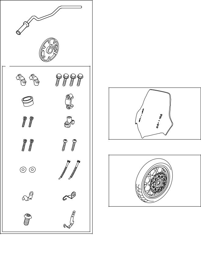
(10)Carton box 3
1
1. Windshield
(11)Front wheel
1
1. Front wheel
5

EAA00120
XT1200Z(Z) SETUP AND PREDELIVERY CHECKLIST
TIP
Check the following items again after setup and predelivery service have been completed.
A: INSTALLATION OF THE PARTS INCLUDED IN THE CRATE
à FRONT WHEEL |
à LEFT REARVIEW MIRROR AND LEFT HAND |
à FRONT FENDER |
SHIELD |
à HANDLEBAR |
à RIGHT REARVIEW MIRROR AND RIGHT HAND |
à RIGHT HANDLEBAR SWITCH |
SHIELD |
à THROTTLE GRIP AND THROTTLE CABLE |
à WINDSHIELD |
HOUSING ASSEMBLY |
à RIDER SEAT AND ABS TEST COUPLER PROTEC- |
à FRONT BRAKE MASTER CYLINDER |
TIVE CAP |
à LEFT HANDLEBAR SWITCH |
à ENGINE GUARD |
à CLUTCH MASTER CYLINDER |
à BATTERY |
à PLASTIC BANDS |
|
B: TIGHTENING TORQUE OF EACH PART
ÃFront wheel axle
ÃFront wheel axle pinch bolt
ÃFront brake caliper bolt
ÃFront wheel sensor bolt
ÃReflector nut (for AUS)
ÃFront fender bolt
ÃUpper handlebar holder bolt
ÃRight handlebar switch screw
ÃThrottle cable housing bolt
ÃFront brake master cylinder holder bolt
ÃLeft handlebar switch screw
ÃClutch master cylinder holder bolt
ÃGrip end bolt
ÃRearview mirror
ÃClutch lever pivot nut
ÃBrake lever pivot nut
ÃHand shield lower bolt
ÃHand shield upper bolt
ÃWindshield screw
ÃEngine skid plate bolt
ÃEngine skid plate nut
72 Nm (7.2 m·kgf, 52 ft·lbf) 21 Nm (2.1 m·kgf, 15 ft·lbf) 40 Nm (4.0 m·kgf, 29 ft·lbf) 7 Nm (0.7 m·kgf, 5.1 ft·lbf)
3.8Nm (0.38 m·kgf, 2.8 ft·lbf) 7 Nm (0.7 m·kgf, 5.1 ft·lbf) 28 Nm (2.8 m·kgf, 20 ft·lbf)
3.5Nm (0.35 m·kgf, 2.5 ft·lbf)
3.8Nm (0.38 m·kgf, 2.8 ft·lbf) 10 Nm (1.0 m·kgf, 7.2 ft·lbf)
3.5Nm (0.35 m·kgf, 2.5 ft·lbf) 14 Nm (1.4 m·kgf, 10 ft·lbf) 27 Nm (2.7 m·kgf, 20 ft·lbf) 17 Nm (1.7 m·kgf, 12 ft·lbf)
6 Nm (0.6 m·kgf, 4.3 ft·lbf) 6 Nm (0.6 m·kgf, 4.3 ft·lbf)
4.5Nm (0.45 m·kgf, 3.3 ft·lbf)
3.8Nm (0.38 m·kgf, 2.8 ft·lbf)
0.5Nm (0.05 m·kgf, 0.36 ft·lbf)
4.5Nm (0.45 m·kgf, 3.3 ft·lbf)
4.5Nm (0.45 m·kgf, 3.3 ft·lbf)
C: ROUTING OF WIRE, CABLES, ETC.
ÃFront brake hose
ÃFront wheel sensor lead
ÃThrottle cable (accelerator cable)
ÃThrottle cable (decelerator cable)
ÃRight handlebar switch lead
ÃLeft handlebar switch lead
ÃClutch hose
ÃABS test coupler lead
ÃNegative battery lead
ÃPositive battery lead
6
D: ADJUSTMENTS
à CHECKING AND CHARGING THE BATTERY |
à BLEEDING THE HYDRAULIC BRAKE SYSTEM |
à MEASURING THE TIRE PRESSURE |
(ABS) |
à CHECKING THE ENGINE OIL LEVEL |
à ADJUSTING THE CLUTCH LEVER |
à CHECKING THE FINAL GEAR OIL LEVEL |
à CHECKING THE CLUTCH FLUID LEVEL |
à CHECKING THE COOLANT LEVEL |
à BLEEDING THE HYDRAULIC CLUTCH SYSTEM |
à ADJUSTING THE THROTTLE CABLE FREE |
à ADJUSTING THE FRONT FORK LEGS |
PLAY |
à ADJUSTING THE REAR SHOCK ABSORBER AS- |
à ADJUSTING THE FRONT BRAKE |
SEMBLY |
à ADJUSTING THE REAR BRAKE LIGHT SWITCH à ADJUSTING THE HEADLIGHT BEAMS |
|
à CHECKING THE BRAKE FLUID LEVEL |
|
E: FUNCTION AND PERFORMANCE
ÃCheck the function of the headlight, meter light and à Check the function of the indicator on the speedom-
taillight |
eter |
à Check the function of the brake light |
à Check the feel of the brakes |
à Check the function of the turn signals and indicator |
à Check engine for irregular noise (Yes/No) |
lights |
à Check for exhaust leak (Yes/No) |
à Check the tone quality of the horn |
|
F: ACCESSORIES, ETC. FOR DELIVERY
à Owner’s manual à Owner’s tool kit
7
EAA00130
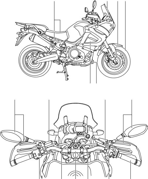
SETUP PROCEDURES
Perform the setup procedures in the order indicated by the numbers. Always follow the order as shown.
13 |
12 |
2 |
1 |
15 14
10 |
8 |
6 |
11 |
7 |
9 |
3 |
9 |
4 |
5 |
8
Loading...